Game-Based Energy Management Method for Hybrid RTG Cranes


1
Key Laboratory of Transport Industry of Marine Technology and Control Engineering, Shanghai Maritime University, Shanghai 201306, China
2
School of Computing and Engineering, University of Huddersfield, Huddersfield HD1 3DH, UK
*
Author to whom correspondence should be addressed.
Energies 2019, 12(18), 3589; https://0-doi-org.brum.beds.ac.uk/10.3390/en12183589
Submission received: 15 August 2019
/
Revised: 12 September 2019
/
Accepted: 13 September 2019
/
Published: 19 September 2019
(This article belongs to the Special Issue Optimal Design and Control of Transportation Energy Saving and Energy Management System)
Abstract
:In order to improve the energy efficiency and economic effect of conventional diesel-powered rubber-tired gantry (RTG) cranes in container terminals, various hybrid RTG cranes were studied. However, these current hybrid RTG cranes have several disadvantages, such as high initial investment cost and poor versatility of energy management methods. In this paper, a hybrid RTG crane consisting of a small-sized diesel generator (DG), a ternary material lithium battery, and a supercapacitor (SC) is studied, and a hybrid RTG crane energy management method based on game theory is proposed. The DG, lithium battery, and SC are modeled as three independent agents to participate in the game, and a multi-agent system (MAS) is established. During the RTG crane work process, agents achieve a coordinated and stable working state through the game, i.e., the Nash equilibrium. Three typical crane operation scenarios, the rated load, continuous work, and intermittent work, are simulated and studied. According to the results, combinations of the three devices can meet the power demand and system performance. The power of the DG in the hybrid system is small (only 20 kW), reducing fuel consumption and overall emissions during RTG crane operation.
1. Introduction
Container ports are important hubs for world commodity trade, where rubber-tired gantry (RTG) cranes undertake container operations in the yard area and are the most common lifting equipment in container ports. The conventional RTG crane uses a diesel generator (DG) as the sole source of energy; however, due to the variable load of RTG cranes, the fuel efficiency of DG is low and generates exhaust gas during operation. It goes against the principles of energy conservation and environmental protection. An RTG crane starts and brakes frequently while working, and has a high frequency of mutual conversion between potential energy and electric energy. When an RTG crane puts down a container, the lift motor acts as a generator, generating regenerated energy. The conventional RTG crane dissipates the regenerated energy through the braking resistor in the form of heat, resulting in a waste of the regenerated energy [1]. The electric RTG cranes can feed this energy back to the grid [2]. However due to the restriction of cable or rail, these RTG cranes can only work in a fixed area, losing the mobility to transfer to another yard.
The variable load characteristic of the RTG crane makes it very suitable for using energy storage devices. Using energy storage devices can save the mobility of RTG cranes. The energy storage devices can absorb the regenerated energy generated during the container descending phase and reduce the peak during the lifting phase, thereby reducing the energy dissipated by the braking resistor. Hybrid RTG cranes with energy storage devices can improve the energy efficiency and reduce fuel consumption accordingly.
Energy storage devices are widely used in various fields, such as electric vehicles [3] and hybrid ships [4]. Common energy storage devices in hybrid RTG cranes include the flywheel, lithium battery, and supercapacitor (SC). The flywheel energy storage technology is a mechanical energy storage method with a large fuel-saving effect. The flywheel energy storage device converts the regenerated energy into kinetic energy of the flywheel, and converts it into electric energy through a synchronous motor coupled with the flywheel rotor when energy needs to be released [5]. The lithium battery is a kind of energy storage device with high energy density. The SC has a low energy density but a high power density and a high dynamic response [6]. The SC can deal with dynamic loads and is suitable for fast storage and release of large amounts of energy.
In recent years, energy management methods of hybrid RTG cranes became research hotspots. In general, energy management methods can be divided into two types: rule-based methods and optimization-based methods.
The rule-based methods have the advantages of clear objectives, simple implementation, and strong real-time performance. In December 2016, Zhao et al. [7] studied the energy storage system of a pure electric RTG crane, with structures incorporating either a lithium battery only or a lithium battery and SC hybrid. The hybrid RTG crane used a control strategy based on numerically efficient filtering. The control structure had two layers: the outer proportional integral (PI) controller controlled the current of the battery according to the difference between expectation and feedback voltage of the SC; the inner PI controller controlled the duty ratio of the direct current (DC)/DC converter according to the demand of the SC. In October 2017, Niu et al. [8] studied a hybrid RTG crane consisting of a 128-kWh lithium battery and a 50-kW DG. The energy control strategy of a thermostat was used to set the state of charge (SoC) operating point of the lithium battery. According to the experimental results, the hybrid RTG crane could reduce fuel consumption by 57.37%. In August 2018, Wei et al. [9] researched a hybrid RTG crane composed of a high-power lithium battery and a low-power DG. The warm-up and cooling time of the DG were considered in the maximum switching power management strategy of the hybrid system. According to the experimental and statistical data, the average fuel saving rate of the hybrid RTG crane was 73.9%. In February 2019, Bolonne et al. [6] studied the energy management strategy of a hybrid power RTG crane consisting of a 200-kW variable-speed diesel generator (VSDG), a 55-kW lithium battery. and a 48.3-F SC. By using the state machine control method, the SoC of the lithium battery was narrowed by 40% to 60%, and the SoC of the SC was kept at about 70%. A small range of SoC can avoid deep discharge and overcharge of the lithium battery, which is beneficial to prolong the cycle life. This control method allowed the hybrid RTG crane to save fuel consumption by 57.5%, compared to a conventional RTG crane.
The optimization-based methods can work better, but the calculation is complicated, and the control system is highly demanding. This type of method has various algorithms and has room for further improvement. In March 2016, Pietrosanti et al. [10] studied the optimal energy management strategy of a hybrid RTG crane equipped with a flywheel energy storage system and a DG. According to the statistical distribution of loads, under the condition of uncertain electrical load duration, the optimal algorithm was used to optimize the use of flywheel storage energy. In simulation, the power of the DG was 200 kW, the flywheel could store 3.34 MJ of energy, and the proposed optimal control strategy could reduce the energy consumption by 38.47%. In October 2017, Alasali et al. [11] studied the energy management of an electrified RTG crane with an energy storage system (ESS). The ESS stored energy during the low-power demand period of a day and released energy during the high-power demand period to reduce the peak demand and electricity cost. The load curve of the RTG crane was predicted using the model predictive control (MPC) method. Based on real-time RTG crane demand and electricity price data, the optimal output of the ESS could be figured out, and the annual electricity bill could be reduced by 7.18%. In October 2018, Alasali et al. [12] introduced a method based on stochastic optimization to study the control of a network of electrified RTG cranes equipped with an ESS. An optimal energy control strategy based on a stochastic model predictive control (SMPC) algorithm was proposed to improve the economy of the network of RTG cranes. According to the results, the SMPC controller achieved a better peak reduction compared to the MPC and set-point controllers. In May 2019, Alasali et al. [13] presented an optimal management system based on genetic algorithm (GA) for the control of a network of electrified RTG cranes equipped with ESS. The stochastic optimal controller was off-line and did not require a load forecast model. The analysis results showed that the GA control model could achieve better peak reduction than a set-point controller.
The output power of a conventional RTG crane’s DG can reach more than 400 kW to meet the maximum lifting power demand. However, the RTG crane has plenty of low load time during operation, where the average power is less than 50 kW. Energy waste is caused by running a high-power DG at a low load. Reducing the size of the DG can reduce fuel consumption and improve fuel efficiency at low load. In order to combine the advantages of the high energy density of a lithium battery and the high power density of an SC, and to fully absorb the regenerated energy, a hybrid system composed of a DG, lithium battery, and SC is studied. Compared with the hybrid system composed of a DG and SC, adding a lithium battery can share part of the average power, reduce the size of the DG, and also absorb part of the regenerated energy. Compared to the system consisting of a DG and lithium battery, adding an SC can deal with dynamic load and reduce the impact of high-current charging and discharging on battery life. In the hybrid system consisting of the three types of devices, the DG provides the average power in its optimal efficiency range, the lithium battery provides the remaining average power that the DG cannot cover, and the SC provides the dynamic power.
The complex relationship between the three different devices challenges the energy management method. The energy management method of the hybrid system is not only required to improve the energy efficiency, but is also expected to prolong the cycle life of the lithium battery. When studying the energy management method, in addition to considering the unique characteristics of each device, their respective preferences should also be fully taken into account. The three devices are modeled as three independent agents that express needs and pursue preferences, and a multi-agent system (MAS) is established. The MAS technology provides a rapid response to condition changes and supports reconfigurability [14,15]. In the MAS, each agent only has a local target [16], i.e., the agent in the MAS only pursues its own goal without considering the overall target of the system.
For a MAS, a decentralized decision-making method or control strategy is naturally needed. Game theory is a mathematical method for studying the interaction between self-interested players/agents. It focuses on decision-making, and each player’s decision can affect the outcome of other players’ decisions [17]. By choosing a strategy, each player strives to achieve its goal [18]. At present, game theory is mostly used for the energy management of smart grids [19,20,21]. The coordinated operation of the hybrid system can be achieved by using a multi-agent strategy and with the help of computer technology [21]. Non-cooperative game theory can be used to analyze the strategy-making process of independent players with conflict preferences [22]. In this study, game theory is used to find the equilibrium strategy that makes the devices work in a coordinated state, and the energy management problem is transformed into a non-cooperative current control game. In the MAS, three devices reach an equilibrium through the game, i.e., the Nash equilibrium. The Nash equilibrium is a balanced solution that takes into account the different preferences of devices and is a strategic balance point for all players to achieve optimal benefits. Using game theory can meet the requirements of hybrid system energy management.
In this paper, a new energy management method is proposed based on game theory. The proposed configuration is based on a low-power DG, a lithium battery pack, and an SC pack. The SC is used to supply transient demand to minimize the current on the battery and to reduce the effect of high current on battery life. The method is established and simulated in Matlab (R2014a, The MathWorks, Inc., Natick, MA, United States). The proposed method is dedicated to achieving higher efficiency while improving the life span of the hybrid energy storage system. This work has the following key contributions:
- (1)
- A new hybrid RTG crane with three energy sources is developed to investigate the fuel consumption reduction and energy efficiency improvement. This will contribute to the limited literature focused on hybrid RTG cranes equipped with multiple energy storage devices.
- (2)
- This work is the first to use the game-based method to solve the energy management problem of hybrid RTG cranes. The proposed method is relatively simple and has the flexibility of expanding or reducing the number of controlled devices.
The structure of this paper is organized as follows: the schematic of the hybrid RTG crane system is described in Section 2. Models of the devices are introduced in Section 3. Section 4 discusses the sizing of the hybrid system devices. The energy management method based on game theory is presented in Section 5. Section 6 analyzes the different working conditions of RTG cranes. Finally, a summary of the work is presented in Section 7.
2. Hybrid RTG Crane
2.1. Schematic of Hybrid RTG Crane System
The RTG crane operating mechanisms include the walking mechanism (gantry), the lifting mechanism (hoist), and the lateral operating mechanism (trolley). The gantry drives the entire RTG crane so that the RTG crane can move in the plane of the container yard. The hoist can lift or descend a container. The hoist is suspended under the trolley, and the trolley moves horizontally on the RTG crane beam. The three operating mechanisms enable the RTG crane to complete loading and unloading container operations in the yard area.
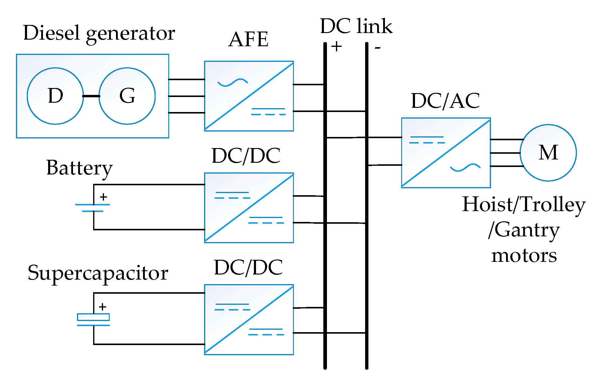
The schematic of the hybrid RTG crane is shown in Figure 1. The DG is connected to the DC bus via an active front end (AFE) that converts the generator alternating current (AC) output to match the system DC link. The lithium battery and the SC are connected to the DC bus through a bidirectional DC/DC converter. The load motor is connected to the DC bus via a DC/AC inverter. This parallel-active topology is an active hybrid topology that provides controlled flexibility, because the devices are controlled by DC/DC converters [23]. In parallel-active topology, the DC bus voltage can also be kept within a stable range [24]. In the energy management method, the output currents of the lithium battery and SC are controlled via their respective DC/DC converters.
2.2. Power Demand for RTG Cranes
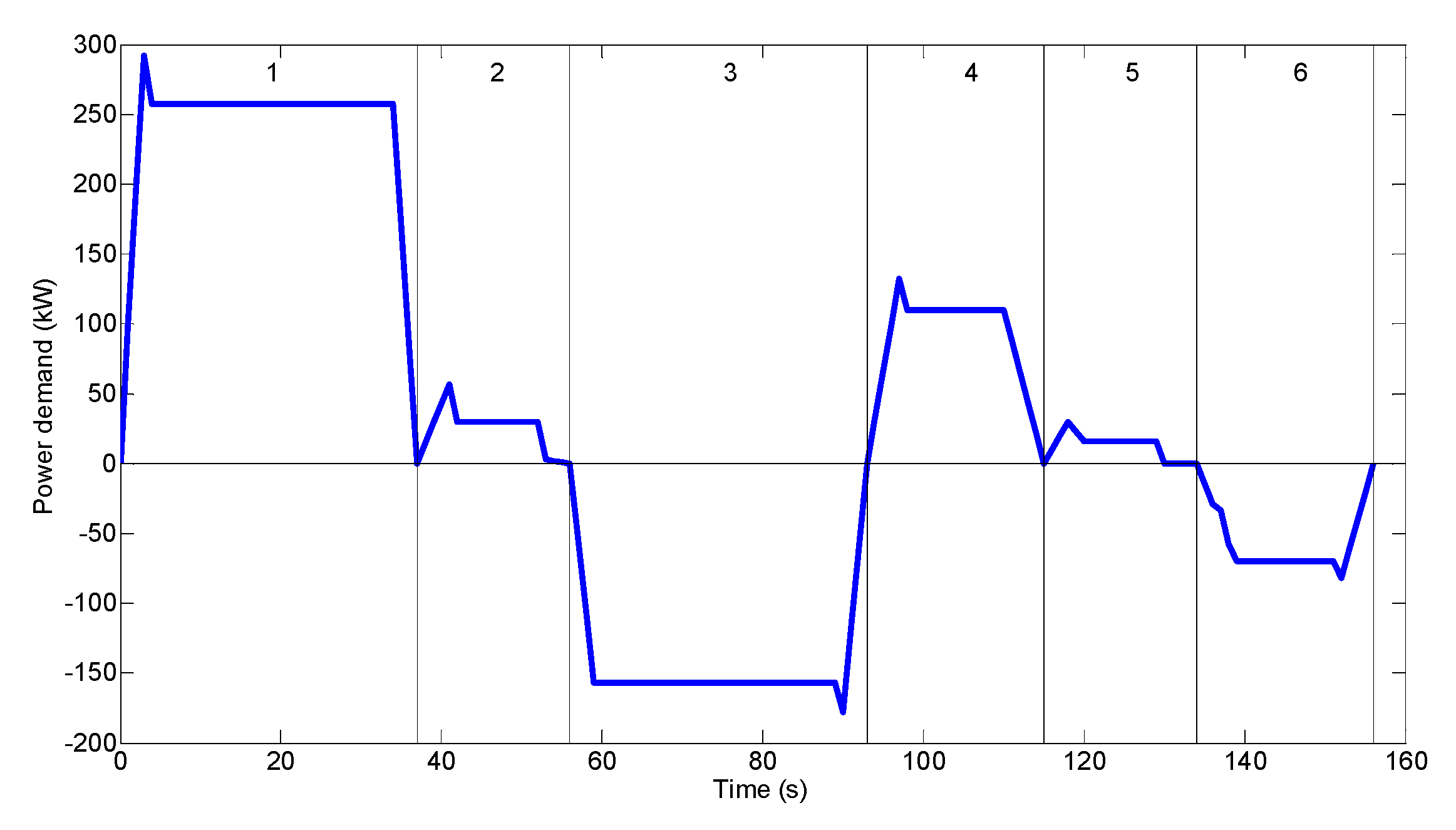
A typical power demand for operating a rated 40-ton container is shown in Figure 2, where the auxiliary equipment power is 7 kW. The peak lifting power is 292 kW and the peak regenerated power is 178 kW [8]. The corresponding operation process of Figure 2 is as follows: in the first stage, the hoist lifts a container; in the second stage, the trolley moves to the right with the container; in the third stage, the hoist descends the container; in the fourth stage, the hoist rises without the container; in the fifth stage, the trolley moves to the left; in the sixth stage, the hoist returns to its original position. Such a process is regarded as an operation cycle. In the operation cycle, the gravitational potential energy and the electric energy are mutually converted. A large amount of regenerative energy is generated when a container is lowered, and the benefit of the hybrid scheme is that this energy is recycled back to the energy storage devices as opposed to being lost in the braking resistor and as heat. The lithium battery and the SC are, thus, utilized to absorb the regenerative energy to improve the overall system energy efficiency.
2.3. Operation Mode of Hybrid RTG Crane
The hybrid RTG crane has three operation modes: the hybrid power mode, the hybrid charging mode, and the standby charging mode. When lifting a container, the power demand is the largest, whereby the DG, lithium battery, and SC are required to output together to meet the power demand; thus, the RTG crane works in the hybrid power mode. When lowering a container, the asynchronous motor of the hoist generates a large amount of regenerated energy. This energy can charge the lithium battery and SC. The RTG crane works in the hybrid charging mode. During idle or standby time, the RTG crane works in standby charging mode, and the DG charges the lithium battery. In the standby mode, if the SoC of the battery reaches the upper limit, the DG stops working. The power requirements for auxiliary equipment are provided by the battery. During the working process, the DG always works in its optimal efficiency range, with the lithium battery providing the remaining average power, and the SC supplying the dynamic power demand.
3. Models of Devices
3.1. DG Model
In the hybrid system, in order to improve the fuel efficiency of the DG, the DG is operated at rated power. When the DG works at rated power, it has high fuel efficiency and low emissions [25,26]. DG converts fuel chemical energy into electrical energy. For the system studied, the fuel consumption is given by Equation (1) [27].
where is the fuel consumption rate and is related to the working environment, load weight, and operating habits, is the output power of the DG, is the duration of work period, and is the sampling time.
3.2. Lithium Battery Model
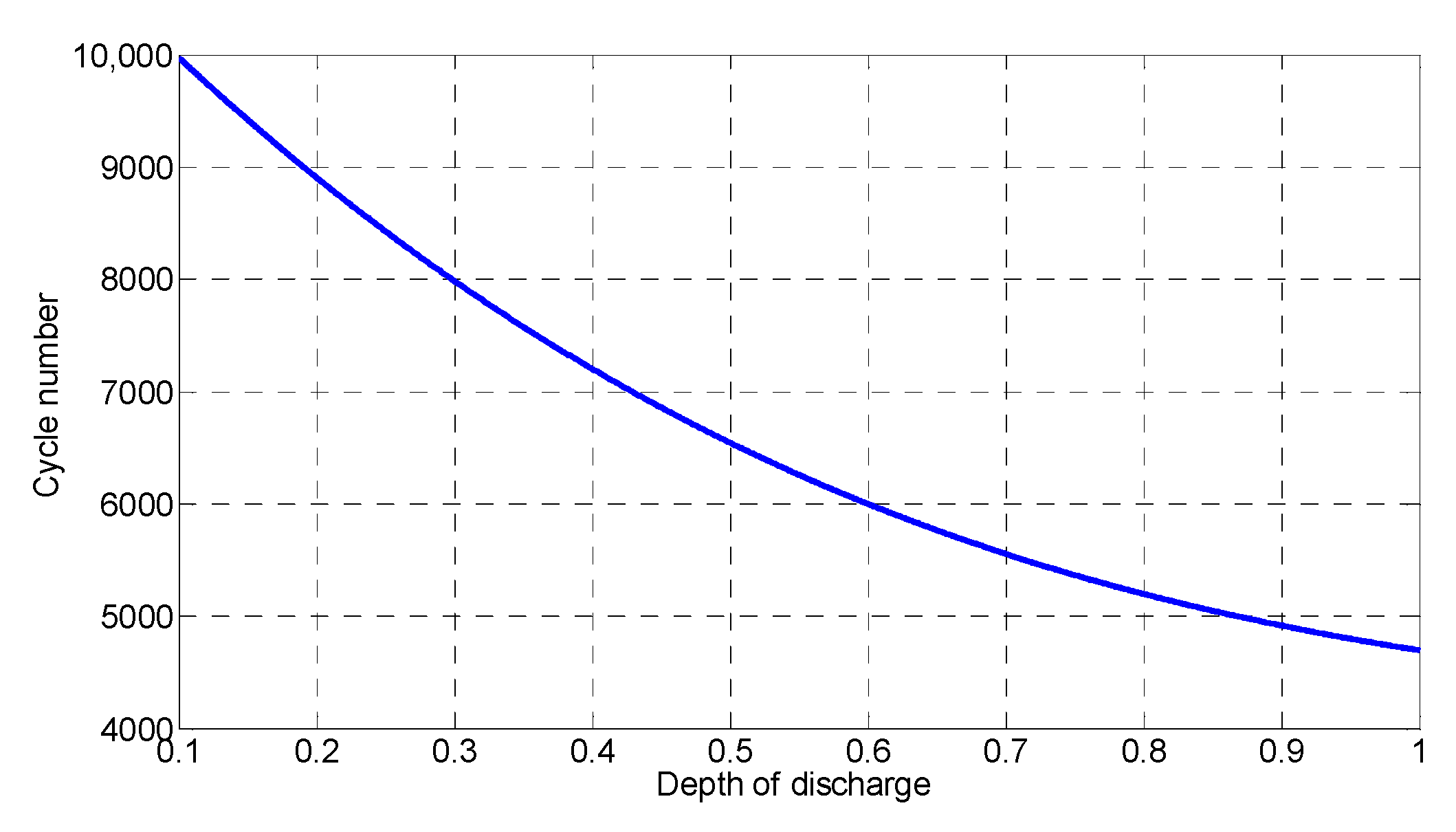
The crane battery uses iYPOWER’s (Shenzhen iYPOWER CO., LTD., Shenzhen, China) ternary material lithium battery modules [28]. Each single module is rated at 48 V and has a capacity of 20 Ah. The module consists of 13 cells connected in series. The size of the battery pack in the hybrid crane system is given in Section 4.2. The relationship between the cycle number and the depth of discharge (DOD) is shown in Figure 3 [29]. As can be seen from the figure, if the DOD of a battery is always 1, the cycle number of the battery is about 4700, and, if the DOD of a battery is always 0.3, the cycle number of the battery is about 8000. Thus, a higher cycle number corresponds to a smaller DOD. The is recorded corresponding to the cycles during a work period. According to the relationship between the number of cycles and the DOD, the battery cycle number is obtained for each . Then, the percentage life-decay rate of the battery is calculated as follows [29]:
The remaining life of a battery is equal to its current life minus the life-decay during the work period. The percentage remaining life of a battery after work periods is, thus, determined as follows [29]:
where is the number of work periods.
3.3. SC Model
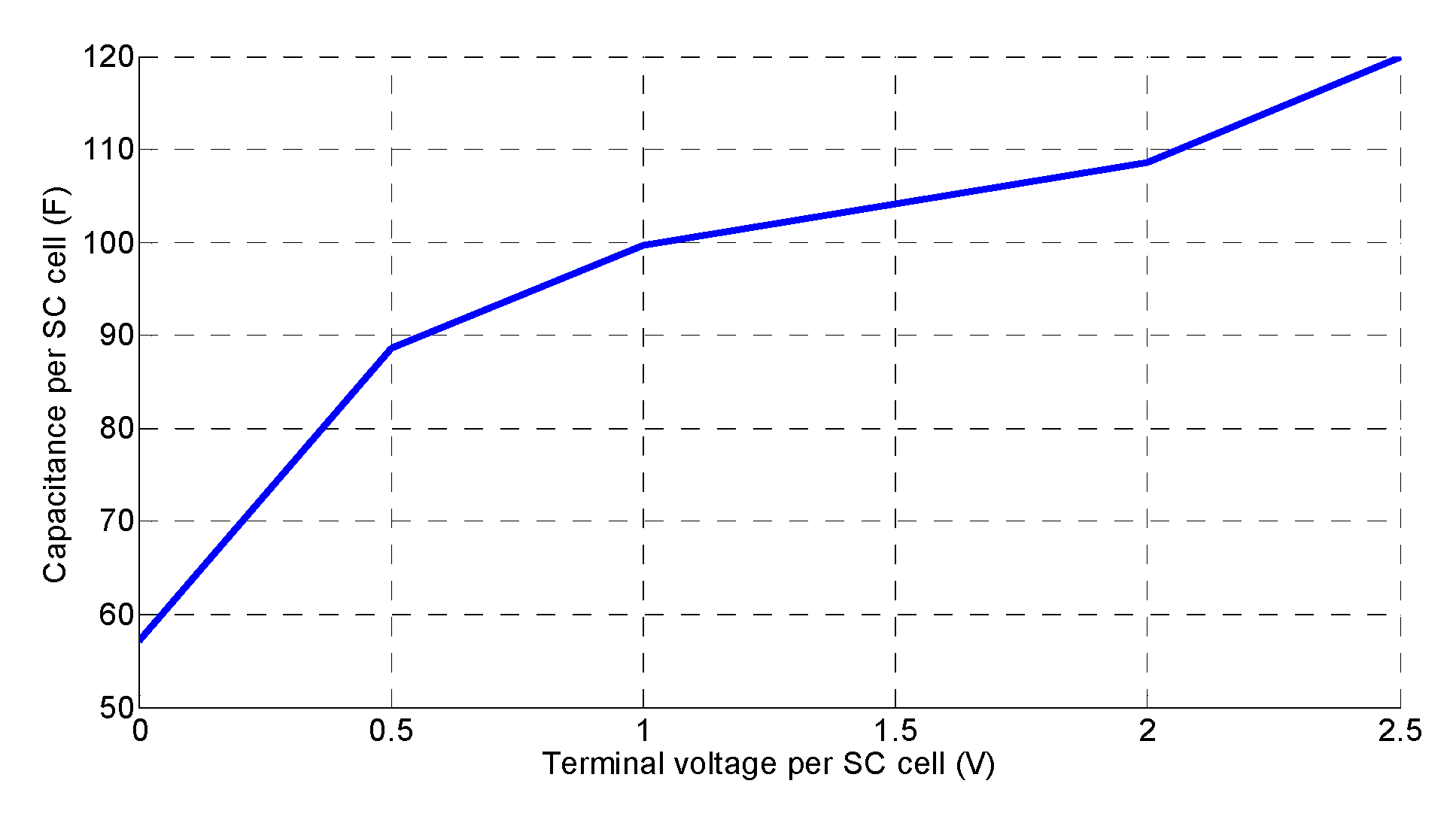
The SC uses Jianghai’s SCMDPS060505QAN SC module (Nantong Jianghai New Energy CO., LTD, Nantong, Jiangsu, China) [30], having a numerical rated voltage if 60 V and capacitance of 5 F. The module consists of 24 capacitors connected in series. Each capacitor has a voltage of 2.5 V and a capacitance of 120 F. The size of the SC pack in the hybrid system is given in Section 4.2. To simplify the SC into a common capacitor, combined with the SC nonlinear capacitance function displayed in Figure 4 [7], the effective storage energy of the SC is calculated as follows:
where is the energy that the SC can store, is the rated capacity of the SC, is the maximum value of the SC voltage, and is the minimum value of the SC voltage. During the discharge of the SC, as the capacitance decreases, the terminal voltage decreases. The relationship between the capacitance and voltage needs to be taken into account during the working process of the hybrid system. The DC/DC converter stops working when the voltage of the SC is lower than the operating voltage of the converter.
3.4. Bi-Directional DC/DC Converter Model
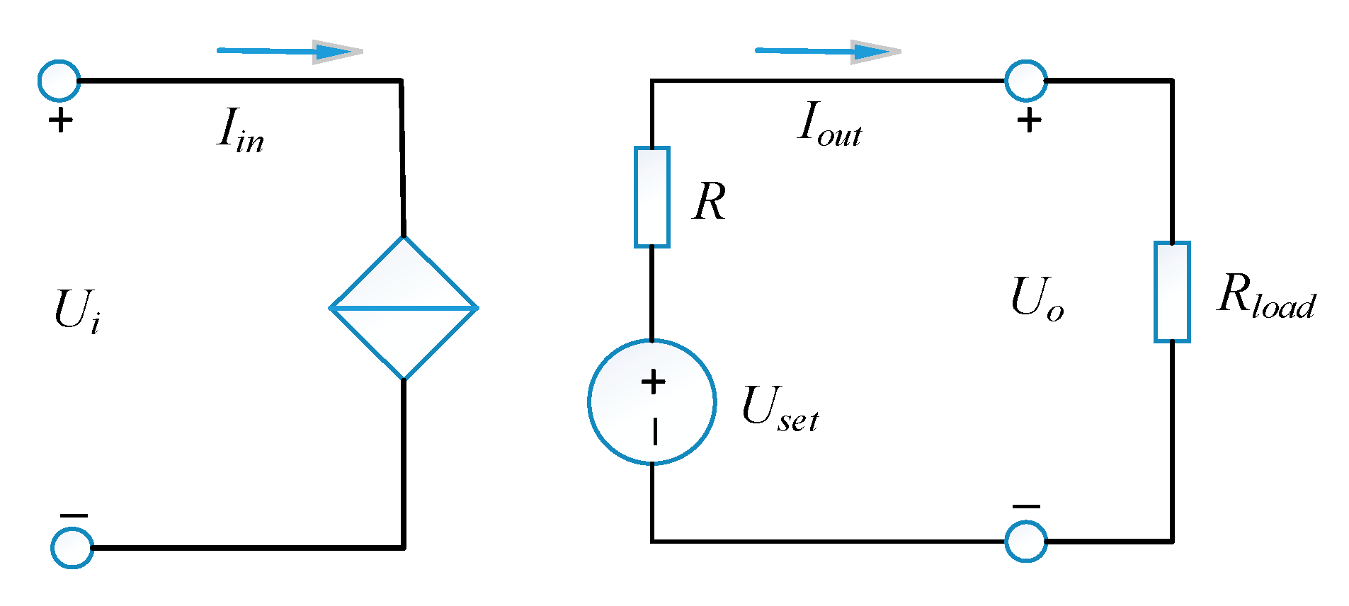
Two bi-directional DC/DC converters connect the lithium battery and SC to the DC bus. Since the voltage on the DC bus is high and stable, the two DC/DC converters work in constant voltage mode on the high-voltage side and can, thus, be modeled as an equivalent voltage source and series resistance, as represented by the equivalent circuit model shown in Figure 5. Here, the output side current satisfies the following relationship:
where is the input-side voltage, is the output-side voltage, is the input-side current, is the output voltage set value, is the equivalent internal resistance of the voltage source, and is the equivalent load on the output side. The minimum voltage on the low-voltage side of the bi-directional DC/DC converter is 150 V [31], and the magnitude of the output current can be controlled by controlling the DC/DC converter.
4. Hybrid System Configuration
4.1. RTG Crane Work Data Statistics
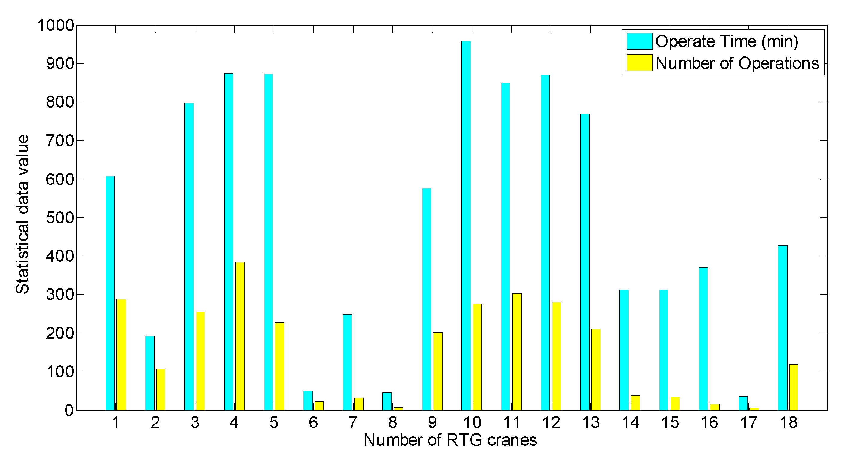
Figure 6 shows the statistics of RTG cranes during a work period in a container port in Hong Kong. There are 18 RTG cranes on the yard, where the average working time is 509 min, the average number of operations is 156, and the average operation time for a single container is 196 s. The working conditions of different RTG cranes are very different. Some RTG cranes have long working hours and a large number of operations (e.g., RTG crane No. 4), some have short working hours and a small number of operations (e.g., RTG crane No. 8), and some have a lot of idle time (e.g., RTG crane No. 16). Considering the working characteristics of the RTG crane, the hybrid system must not only meet the requirements of continuous operation, but also make full use of the idle time.
4.2. Sizing of Hybrid System Devices
Proper sizing of devices is important, and a continuous optimization process is needed when adjusting the size of the devices [7]. The sizing of devices discussed below is an example to verify the proposed energy management method. The average power of the typical working condition is about 24.8 kW [8]. In the hybrid system, the DG and lithium battery work together to meet the average power demand. The rated output power of the DG is 20 kW, and the rest of the average power is provided by the lithium battery. The SC is responsible for providing dynamic power to meet the peak power requirements. The SC pack consists of 44 SC subsystems in parallel, and each SC subsystem consists of 10 SC modules in series. The SC pack is rated at 600 V and has a capacity of 22 F. In the system structure, the SC is connected to the DC bus through a bi-directional DC/DC converter. Since the low-side voltage of the bi-directional DC/DC is limited to 150 V, the minimum voltage of the SC cannot be lower than 150 V. According to Equation (4), the available capacity of the SC is 3.7 MJ.
During the discharge period of the SC, the terminal voltage decreases continuously. When the terminal voltage drops to 150 V, the maximum output power decreases to 91.5 kW. In order to meet the 255-kW power demand of lifting a 40-ton container at this time, the battery should replenish this part of the power in time; thus, the maximum power of battery is 143.5 kW. The ternary lithium battery supports a 2-C discharge and a 1-C charge. The battery pack consists of seven battery subsystems in parallel, and each battery subsystem consists of 11 battery modules in series. The terminal voltage of battery pack is 528 V and the capacity is 140 Ah. The maximum output power is 147.8 kW. In order to avoid the impact of deep discharge and overcharge of the cells in the battery pack, the SoC variation of the battery is limited to between 0.5 and 0.8, and the available capacity of the battery is 22.18 kWh. In the hybrid system, the lithium battery pack is responsible for providing the average power that the DG cannot meet. The average power of operating a 40-ton container is 42.8 kW. Due to the short duration, the battery only needs to provide about 0.6 kWh of energy. In addition, when the average power is less than 20 kW, the excess average power can also charge the battery; thus, the battery capacity selection is completely sufficient.
In summary, the power of the DG is 20 kW; in order to improve fuel efficiency, it keeps working at its rated power. Compared to a conventional RTG crane with a 300-kW DG, the power of the DG in the hybrid system is only 6.7% of that value, which reduces investment costs and operating costs. The capacity of the lithium battery is 73.9 kWh; compared with the 128 kWh lithium battery in Reference [8], the capacity of lithium battery is reduced by 42%, which reduces the investment cost. The available capacity of the SC is 3.7 MJ. In addition, when the SC is filled with regenerated energy, although the lithium battery can absorb regenerated energy, part of the regenerated energy cannot be absorbed in time. Due to the limitations of SC capacity and lithium battery charging current, the braking resistor is needed to consume this excess energy.
5. Hybrid System Energy Management Method
This section presents the energy management method based on game theory. The basic assumption of game theory is that the players in the game are rational. A rational player means that his purpose of a specific strategy is to maximize his own benefits while considering the strategies of other players. These rational players constitute a game. The Nash equilibrium is a strategic balance point for each player to achieve maximize benefits. A common phenomenon in life can be used to explain the Nash equilibrium, e.g., price wars. Several manufacturers producing the same product form a stable state in which the price of the product remains basically the same. In this case, each manufacturer’s strategy for the price forms a Nash equilibrium. If one of the manufacturers breaks the equilibrium and begins to cut prices in order to gain more profit, the other manufacturers follow up and push each other down. The manufacturer who initially cut the price eventually suffers losses. Thus, no manufacturer takes the initiative to break the equilibrium.
5.1. Control Schematic and Devices Preferences
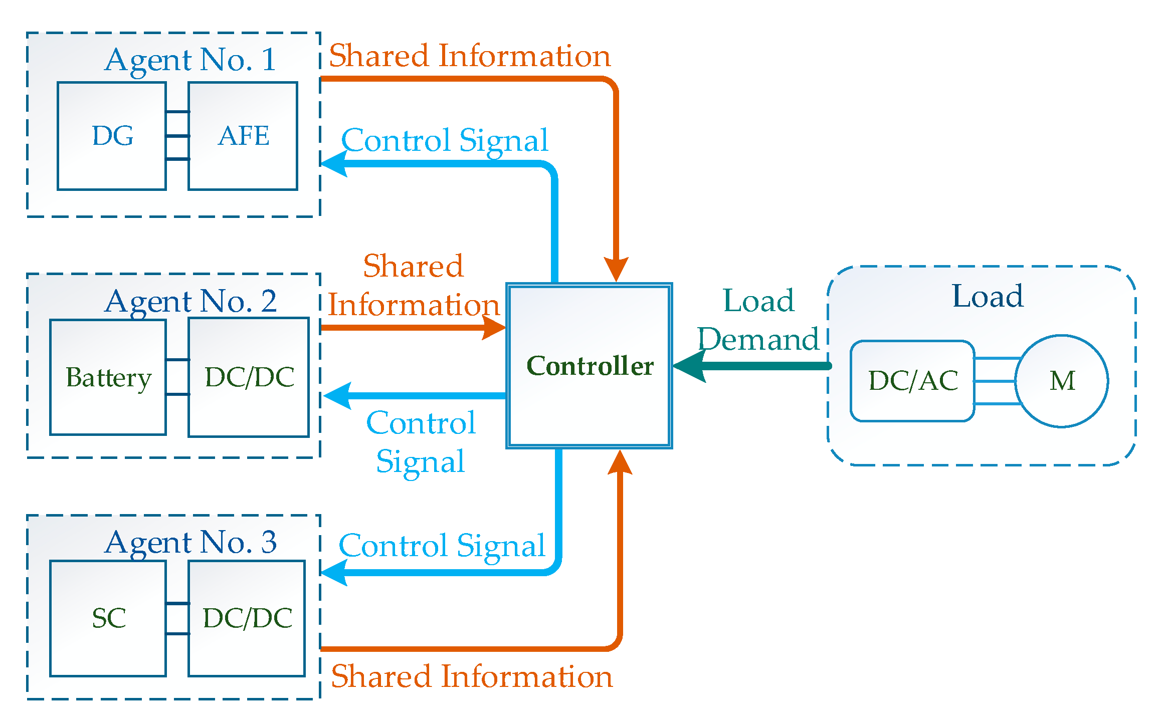
In the game, the device’s strategy is the magnitude of its output current. Note that the currents here and below are the values observed from the DC bus side. For the lithium battery and SC, the current may also be negative, which means charging. Figure 7 presents the schematic of the proposed energy management method. The DG, lithium battery, and SC are the three agents taking part in the game. The three devices output the shared information to the controller, and the controller calculates their respective strategies. Then, the controller converts the results of the game into control signals to control the three devices. The shared information is discussed in Section 5.3.
The preference of a device depends on its unique characteristic. The DG can work for a long time, but the energy efficiency and emissions of the DG depend on the generator load; when the DG changes its load, its energy efficiency is low and the exhaust gas emission increases [32]. It is of great significance to make the DG work in the optimal efficiency range and to reduce the number of starts and stops to improve fuel efficiency. Therefore, the preference of a DG should be to improve fuel efficiency, and the best strategy is to work at rated power. Due to the high price and short cycle life of a battery pack, in order to improve the economic effect of the system, the preference of the battery pack is to prolong the service life. The factors affecting the cycle life of a lithium battery include temperature, depth of discharge, and discharge rate. In addition to the temperature factor, the best strategy for the battery pack is to control the depth of discharge and reduce the discharge rate. The SC has long cycle life but limited energy density. As an auxiliary energy storage device, the SC can provide fast and efficient energy output, and improve the efficiency and dynamic response performance of the whole system. Thus, the preference for the SC is to provide dynamic load. After determining the preferences of devices, the benefit of each device can be maximized by the game, and the efficiency is improved for the whole system.
5.2. Utility Function
The relationship between the strategy and benefit of an agent is formulated as a utility function. In the game theory, each player measures the benefit of the strategy through its utility function. The utility function is typically defined via quadratic form [33]. There are other forms of utility functions in the literature, such as linear functions and logarithmic barrier functions [34,35]. Linear functions may not guarantee a unique Nash equilibrium. Compared with logarithmic functions, quadratic functions are simpler, and the amount of computation is smaller. In this work, the quadratic form was chosen because the concavity of quadratic functions has the property of guaranteeing the existence and uniqueness of the Nash equilibrium [24]. It is a widely used form to model the preference of players [33,36]. The quadratic form of the utility function is as follows [24]:
where is the utility function, is the device output current, and , , and are the coefficients. These coefficients are different according to the characteristics of devices in hybrid systems.
Applying this theory to the control of hybrid cranes, the utility function can be designed to reach its maximal value when the output currents of the hybrid system devices are equal to their output currents under the best strategies. In the hybrid RTG crane consisting of a DG, lithium battery, and SC, it is significant to ensure that the outputs of the devices meet the requirement of the crane’s work. The error between the currents supplied by the devices and those required by the crane is taken as one term of the utility function. The introduction of the error term into the utility function can make the decisions of the devices converge in the direction of reducing the error. The influence of the error on different devices is discrepant due to their different characteristics. In other words, for each device, the coefficient of error is different. In order to clarify the meaning of each term, the utility function is written in the form of a quadratic multinomial. The utility function in this hybrid RTG crane is designed as follows:
where is the current strategy variable of the device, is the expected current strategy of the device, is the adjustment coefficient, is the current required by the load, is a constant, and is the sum of the currents provided by the three devices. In a stage of the game, before the device decides its strategy, the error in its utility function is calculated first as a specific value. Thus, the utility is in quadratic form. The currents provided by the three devices are calculated as follows:
where , , and are the currents supplied by the DG, lithium battery, and SC, respectively. The positive value represents the release current, and the negative value represents the absorption current. In the utility function, the first item reflects the satisfaction of the expected strategy. The closer it is to the expected strategy, the higher value the utility can achieve. The second term reflects the error between the load demand current and the total output current. The smaller the error is, the larger the value the utility function can achieve. In order to improve the utility, each agent has a tendency to reduce the error. The coefficient reflects the sensitivity to the error. The larger the coefficient is, the more sensitive it is, i.e., a larger current change can be used to reduce the error. The last term is a constant that keeps the utility function positive.
According to the form of the utility function defined in Equation (7), the utility function of the DG is as follows:
The utility function of the lithium battery is as follows:
The utility function of the SC is as follows:
In these three equations, , , and are the expected currents of the DG, lithium battery, and SC, respectively, whereas , , and are the coefficients that adjust the influence of the error on the utility function. The specific values in the simulation are given in Section 6.1. As a player in the game, the preference of the DG is to improve its fuel efficiency. Its strategy is to work at rated power and maintain an optimal output current, as shown in Equation (12).
where is the output current of the DG operating at rated power.
The lithium battery in the hybrid system provides a partial average power. The preference of the lithium battery is to prolong its cycle life. Under the premise of guaranteeing the variation range of SoC, the expected strategy of lithium battery is adjusted according to the power demand. According to the working characteristics of hybrid RTG crane, the expected strategy of the lithium battery is shown in Equation (13).
where is the DC bus voltage, and is the output power of the lithium battery. When the power of the DG is greater than the average power demand, excess power can be used to charge the lithium battery.
The SC can fill the peak power demand gap that the DG and lithium battery cannot provide due to its high dynamic response speed. Its preference is to provide dynamic power. In order to guarantee the response speed to the dynamic power demand, the expected strategy of the SC should be zero. Thus, the SC maintains the same response speed to charge and discharge, as shown in Equation (14).
The SC acts as a power buffer; in order to prevent the SC from running out of energy, it is expected that the energy released by the SC after an operation cycle is equal to the absorbed energy, as shown in Equation (15).
where is the SC energy, is the sampling time, and is the duration of the operation. The higher the SoC of the SC is, the higher its efficiency is. When the SoC is 1, the SC has the highest charge and discharge efficiency [37]; thus, the SC achieves full charge, which is beneficial for improving the hybrid system’s efficiency.
5.3. Information Sharing
In the game, each player has to share its strategy information to other players, i.e., , , and are shared information. The utility function of each device contains the shared information. If one of the devices wants to increase its benefit, it needs to consider the strategies of the other two devices. When an equilibrium is reached, the error between the demand and the total output is zero. If a device wants to change its strategy while other devices’ strategies remain the same, it is bound to increase the error and reduce the device’s benefit. Thus, when the equilibrium is reached, all devices have no incentive to change the strategy.
5.4. Nash Equilibrium
The utility functions of the three devices are , , and . The game can be described in the form of [38]. By adjusting the strategies between devices, the non-cooperative current control game reaches the Nash equilibrium. The Nash equilibrium is a compromise load distribution that balances the different preferences of each device [39]. The strategy variable space is a non-empty tight convex set in Euclidean space, and the utility is a continuous quasi-concave function of the strategy; thus, the non-cooperative current game has a pure strategy Nash equilibrium [34]. By solving the Nash equilibrium, the hybrid system works at an optimal balance point. Working at this point, the system is efficient and helps to prolong battery cycle life.
5.5. Solving Nash Equilibrium
In this paper, an algorithm for solving the Nash equilibrium is designed based on the iterative search method, which is a commonly used method for solving Nash equilibrium [20,24,34]. In the multi-round process of a single stage of the game, each player adjusts its utility function based on the shared information and makes the current strategy that maximizes its benefit. The error reflects the influence of the strategy on the result. During the iterative process, the error is continuously reduced, and the strategies of the players converge to the stable solution, i.e., the Nash equilibrium solution. The Nash equilibrium solution is shown in Algorithm 1.
| Algorithm 1. Nash equilibrium solution algorithm |
| 1. Initialize , , and . |
| 2. Input power demand , each player determines its utility function. |
| 3. Save historical strategies, , , and . |
| 4. The players calculate the , , and that maximize their utility function. |
| 5. Share information; if , , and , go to 7; else, go to 6. |
| 6. Each player adjusts its utility function based on the shared information; go to 3. |
| 7. Get the Nash equilibrium; output results, , , and . Go to 2. |
According to the above process, it can be concluded that the time complexity of the algorithm is . The average calculation time is reported in Section 6.5. After inputting a power demand, a new stage of the game is started, and each player adjusts its expected strategy according to the input power demand and then determines the utility function. The maximum value of the utility function can be obtained by the derivative equation. Taking DG as an example, the strategy that maximizes its utility function can be obtained by the following equation:
According to Equation (9) and simplifying, the following equation can be obtained:
According to Equation (17), under the premise that the load demand , the lithium battery output currents , and the SC output currents are known, the strategy that maximizes the utility of the DG can be calculated directly. The calculations of the other two devices are similar.
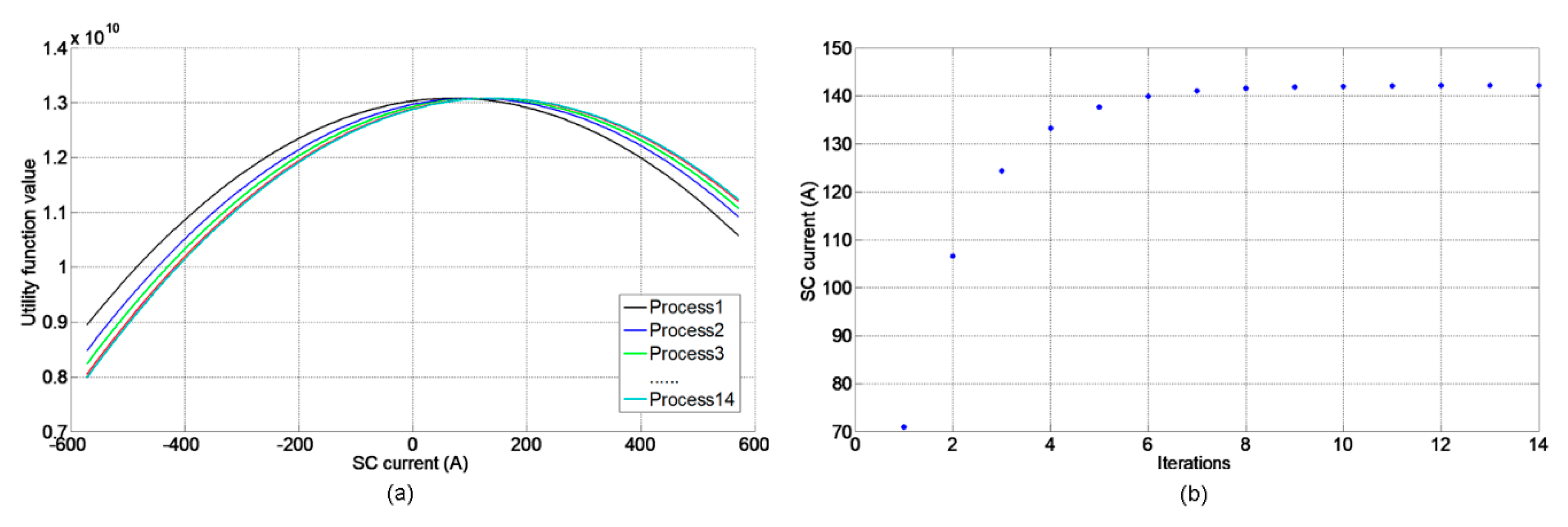
After the three devices obtain their strategy, the strategy information is shared. If the difference between two procedures is less than the threshold , it is considered that the game reaches a stable state, i.e., Nash equilibrium. If the difference of a device is greater than the threshold, the utility function needs to be adjusted to recalculate the strategy to reduce the difference. In that stage of the game, taking the SC as an example, the adjustment process of the utility function and the strategy are shown in Figure 8. It can be seen from Figure 8a that, as the game progresses, the utility function of the SC is adjusted continuously. This reflects the influence of the change in device strategy on the utility function. In Figure 8b, the strategy of the SC gradually approaches a stable value. When the strategies of the three devices reach stable values, the Nash equilibrium of the game is reached.
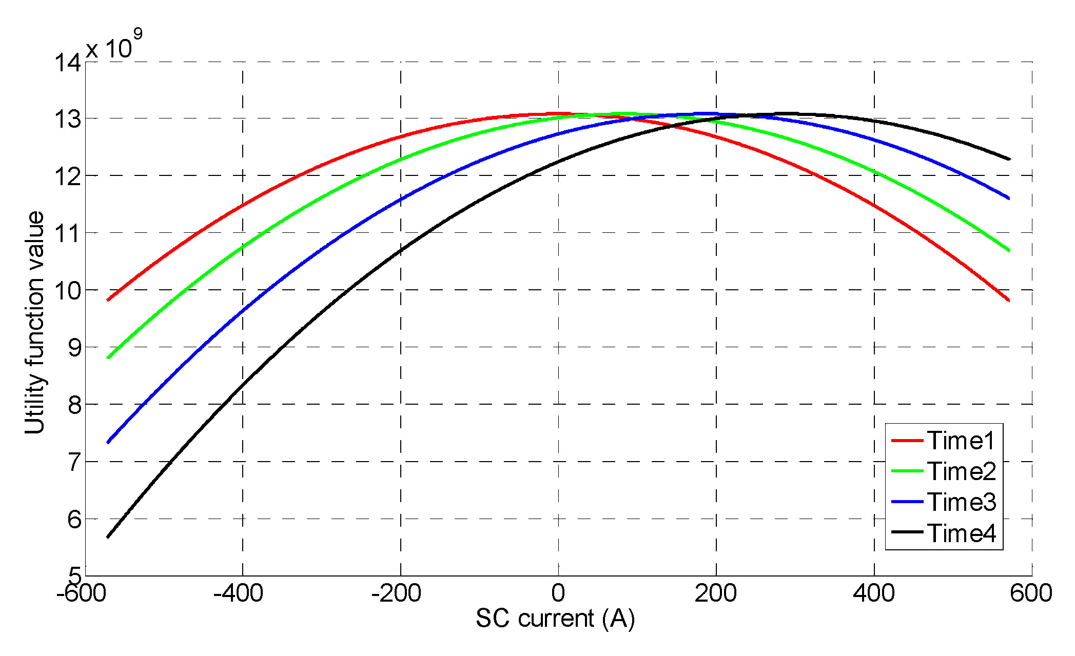
After reaching the Nash equilibrium, the system waits for the power demand input at the next moment to enter a new stage of the game. Each control moment is considered as an independent stage, because, in actual operation, although the power demand inputs are the same, the state of the device may be different. For example, if the SoC of the battery is constantly changing, the decision of the device may be different at different SoCs. Thus, even for the same power demand input, a new stage of the game is needed. In a new stage, each device is concerned about how to make a strategy to maximize its benefit. At each control instant, the Nash equilibrium is iteratively obtained according to the Nash equilibrium solution algorithm. Taking the first four seconds of the RTG crane operation as an example, the change in SC utility function is shown in Figure 9. According to Figure 2, the first four seconds are the acceleration phase, where the power demand is increasing. The maximum value of the utility function in Figure 9 is also moving in the direction of increasing the SC current. This shows that the utility function is adjusted for different power requirements. Thanks to the rapidity of the Nash equilibrium solution algorithm, even if a new game is played, it can meet the real-time requirements.
5.6. Flexibility and Expansibility of the Energy Management Method
The proposed energy management method can be flexibly applied to different hybrid system configurations. For example, in order to meet the different working characteristics of different ports, the configuration of the hybrid system is different. For this method, the only difference is that the utility function of each device is different. By adjusting the utility function of each device, this method can be easily applied to different configurations of hybrid systems. If only two devices are used to form a hybrid system, two devices can still form a game. Through the game, two devices can work in a coordinated and stable state.
Due to the dispersion of this method, the game theory approach can be extended as a general solution to manage complex hybrid systems and involve more devices [39]. In order to add a new device to the hybrid system, one only needs to write the utility function according to Equation (7), obtain the expected strategy based on its characteristics, and then adjust the coefficient according to the simulation and experimental results.
6. Simulation Analysis
Three typical RTG crane operation scenarios, the rated load, continuous work, and intermittent work, are simulated and studied in this section.
6.1. Simulation Parameters
The energy management method of the hybrid RTG crane was simulated in Matlab (R2014a, The MathWorks, Inc., Natick, MA, United States). The central processing unit (CPU) model of the computer used for the simulation was an Intel (R) Core (TM) i5-6300HQ CPU (Intel Corporation, Santa Clara, CA, USA) at 2.30 GHz. The main parameters in the simulation are listed in Table 1. The current of the lithium battery and the SC in the table refers to the current on the device side.
At the beginning of the simulation, the battery SoC was 0.7 and the SC SoC was 1 to cope with the high-power demand of lifting a container in the first stage of Figure 2. The coefficients of the utility function could be adjusted according to the threshold and time requirements. The coefficients in the simulation are shown in Table 2. Compared with other coefficients, the DG coefficient was very small. This is because the DG is expected to work in the optimal efficiency range. The smaller the coefficient is, the less sensitive it is to the change in power demand. Its output power can, thus, remain stable.
6.2. Rated Load Simulation
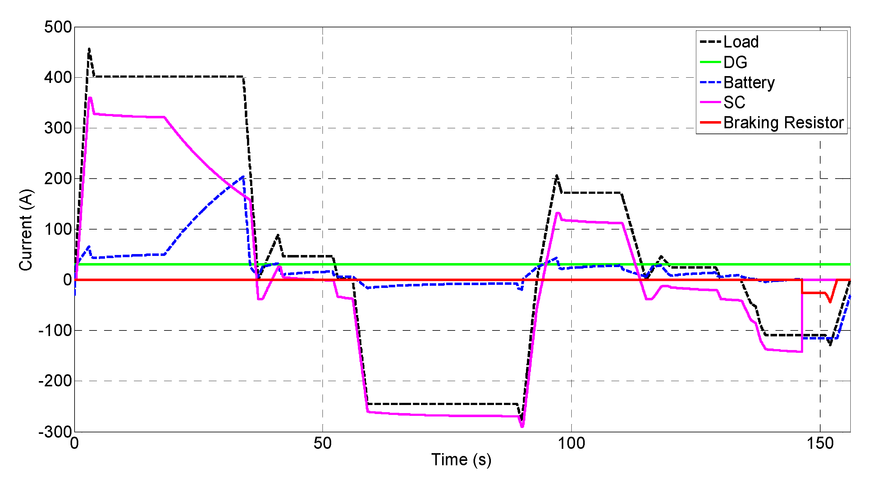
The results of the RTG crane operating a rated 40-ton container are shown in Figure 10. According to the power demand in Figure 2, the load current demand in Figure 10 was derived. The outputs of the DG, lithium battery, and SC together met the load demand. It was considered that the DG was started before RTG crane started work; thus, the DG reached the rated output at the beginning of simulation. At the acceleration phase, the output current of the SC rapidly increased to meet the high-power demand of the transient. In the phase of constant speed lifting, the power demand was stabilized, and the DG, lithium battery, and SC jointly met the power demand. With the discharge of the SC, its capacity decreased and the terminal voltage dropped, as shown in Figure 4. The decrease in SC voltage led to the decrease of its output power and the decrease of current output to the DC bus. By the 18th second, the output current of the SC began decreasing. In this case, only by increasing the output current could the lithium battery maximize its benefit, because the output current of the SC was already the strategy to maximize its utility. If the lithium battery did not increase its output, the error would increase. By the 56th second, the RTG crane began lowering the container, and the DG was still working to provide the average power, representing the average power source of the whole operation cycle.
During the container drop phase, both the lithium battery and SC had negative currents. These negative currents were charging currents. The charging currents were also the result of the game. It can be seen that the charging current of the SC was much larger than that of the lithium battery. This is because the SC had a more sensitive current change than the lithium battery, i.e., the coefficient of the SC in Table 2 was bigger. Finally, around the 151th second, the SC was fully charged, and its charging current was reduced to zero. In this case, due to the lack of competition from a faster SC, the charging current of the lithium battery increased rapidly, reaching its maximum charging current. Certainly, it can be seen from the Figure 10 that, due to the charging current limitation of the lithium battery, the charging current of the lithium battery was lower than that of the SC. The rest of the current would be dissipated by the braking resistor; however, this value was small and the duration was also short, as shown by the red line in Figure 10. This also shows that the use of two energy storage devices could efficiently absorb the regenerated energy.
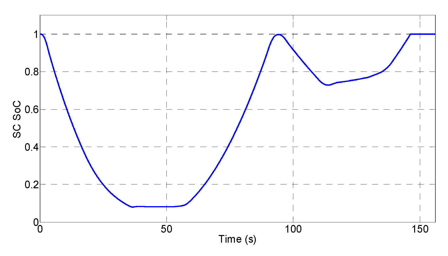
During the cycle of operating a 40-ton container, the SoC of the SC was as shown in Figure 11. When lifting the container, the SC quickly output large current to meet the power demand, and its SoC decreased rapidly; when lowering the container, the SC quickly absorbed the regenerated energy, causing its SoC to rise. The subsequent smaller SoC change was caused by the lifting and lowering of the 11-ton spreader. By the 151th second, the SC was full of electricity and its SoC reached 1. Until the end of operation cycle, the SC absorbed enough regenerated energy to cope with the next container operation, meeting the requirement of Equation (15).
6.3. Continuous Work Simulation
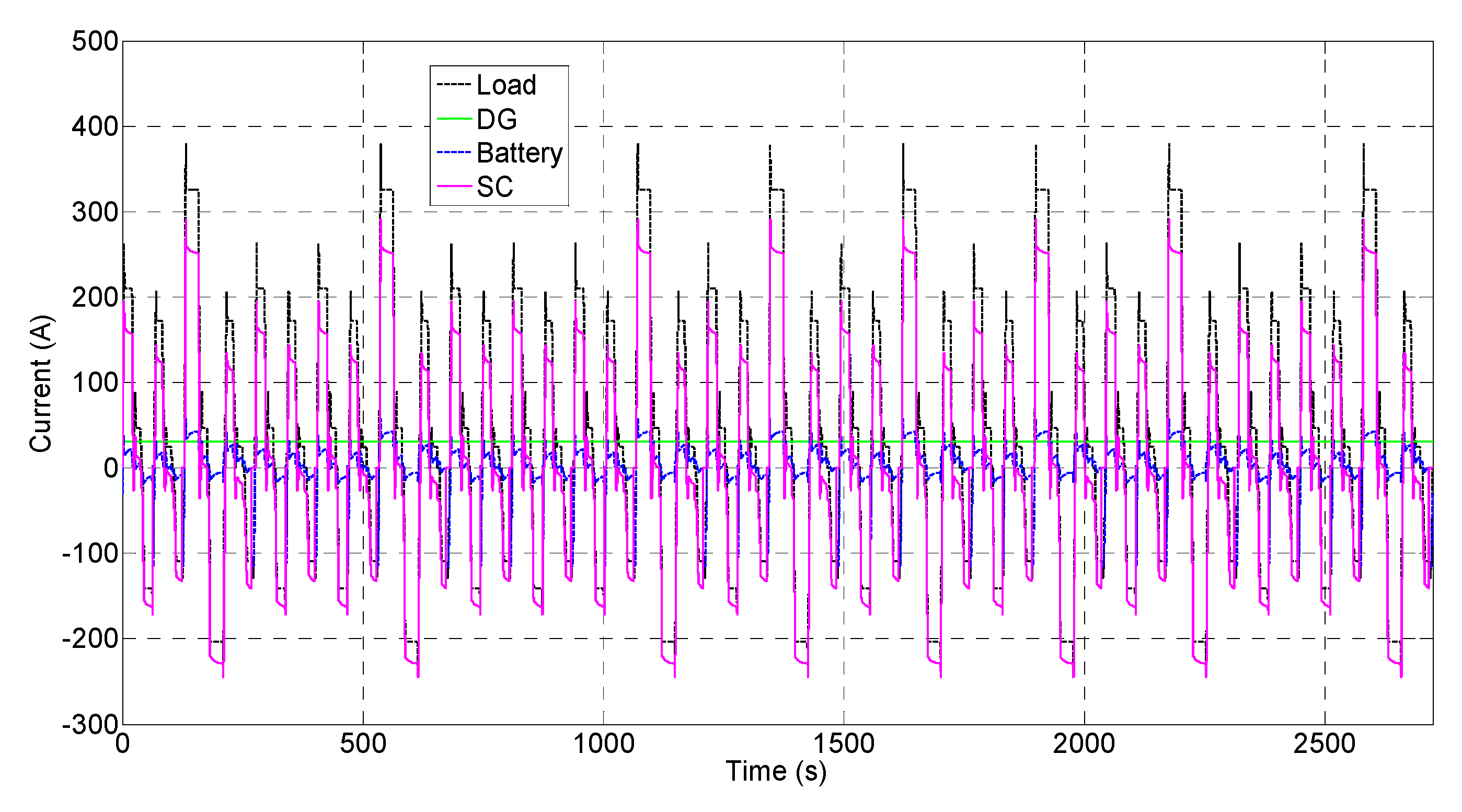
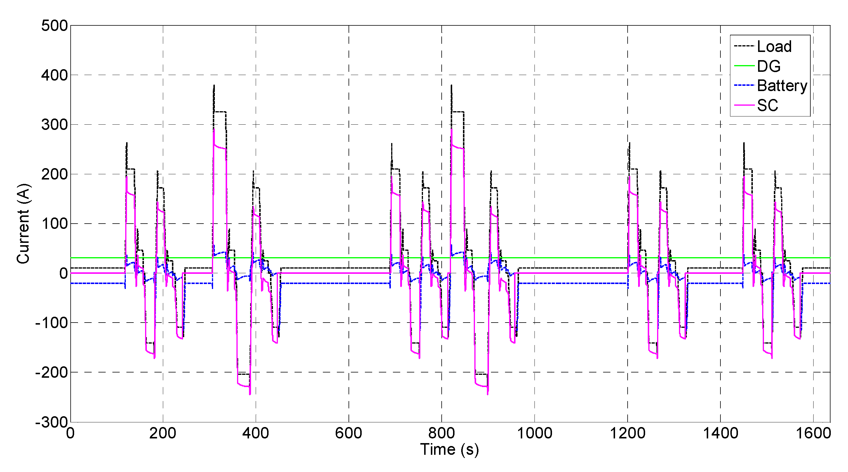
In order to verify the effectiveness of the energy management method in RTG crane continuous work, the operations for two typical weights, 15 tons and 30 tons, were repeated several times. The results of continuous work are shown in Figure 12. Whereas the 15-ton container was operated 12 times, the 30-ton container was operated eight times, and the average power for the whole work period was 20.5 kW. During the working process of the RTG crane, the output of the DG remained constant, the lithium battery provided the average power that the DG could not meet, and the SC dealt with the dynamic power. The current dissipated by the braking resistor was also very small, and the absorption efficiency of regenerated energy was calculated as described in Section 6.5. The SoC of the lithium battery is shown in Figure 13. When operating the 15-ton container, the average power demand for the operation cycle was less than the output power of the DG, whereas the lithium battery absorbed the excess power of the DG and its SoC increased slightly. When operating the 30-ton container, the average power demand was greater than 20 kW, whereby the lithium battery needed to provide a part of the average power, and its SoC decreased.
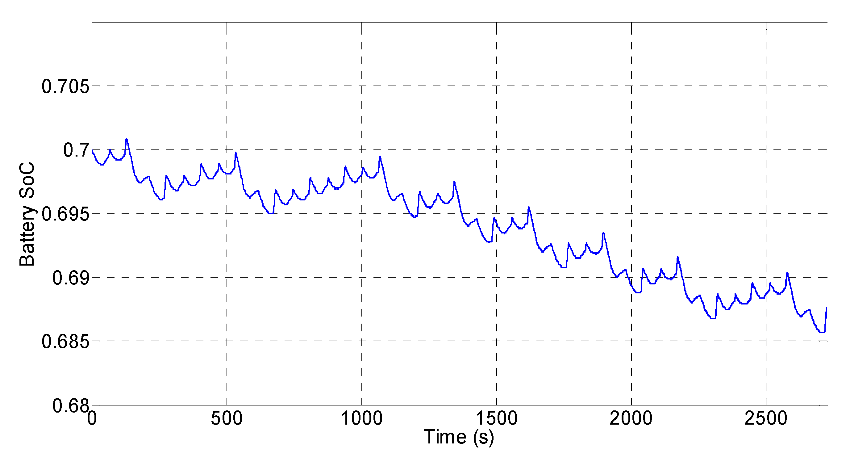
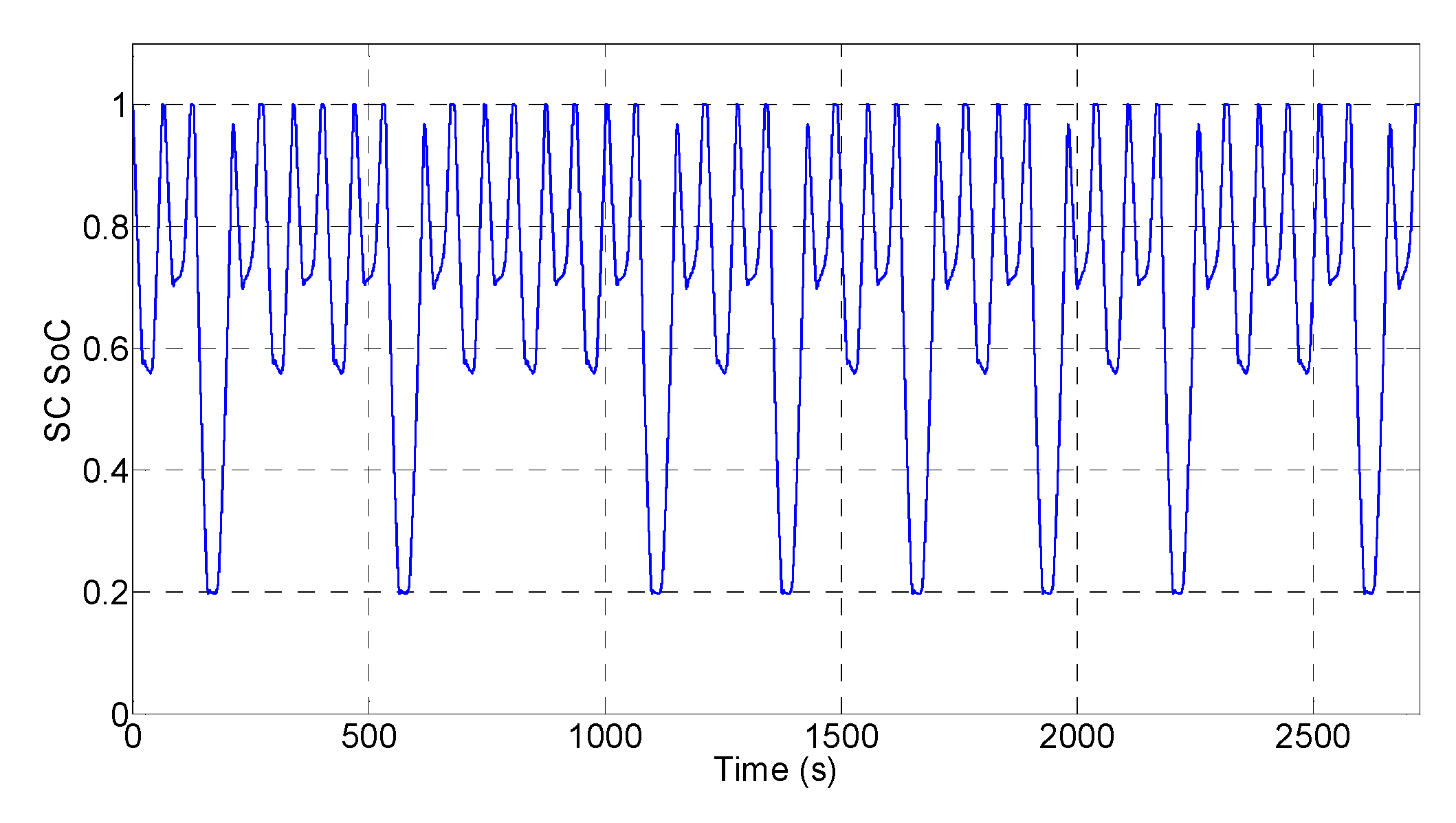
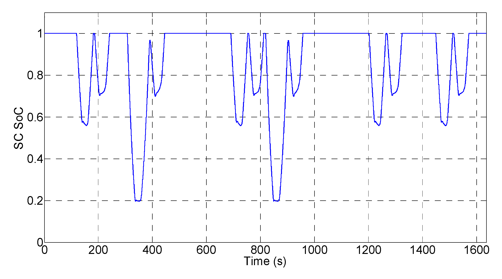
After 20 consecutive cycles of operation, the SoC of the lithium battery dropped from 0.7 to 0.686. This is because the average power (20.5 kW) of the continuous work was higher than the output power of the DG. The lithium battery needed to provide a part of the average power. According to the SoC utilization range in Section 4.2 of 0.5 to 0.8, the capacity of the lithium battery could satisfy such a test 20 times, i.e., the RTG crane could operate 400 containers continuously. This value is already greater than the maximum container operation number 384 in Figure 6, showing that the proposed system configuration can meet the continuous work requirements. If there is idle time between two operation cycles, the output power of the DG during this time can charge the battery, further increasing the battery operating time. The SoC of the SC is shown in Figure 14. It can be seen from the figure that the SoC of the SC could return to 1 at the end of each operation cycle. The SC provided the dynamic power and acted as a power buffer.
6.4. Intermittent Work Simulation
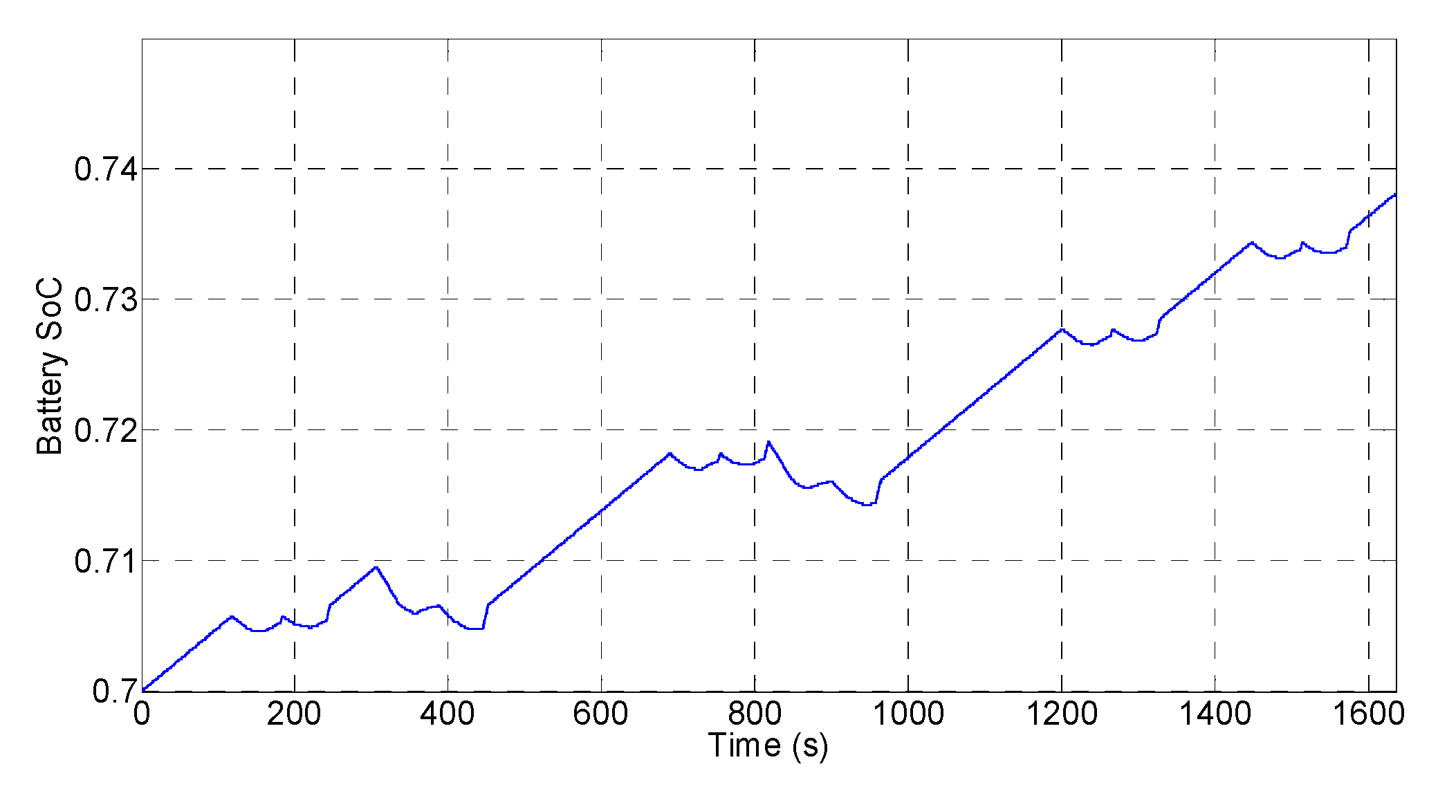
When the port is not busy, there is idle time between two operations. During idle time, the RTG crane had an auxiliary power of 7 kW. The results of intermittent work are shown in Figure 15. In about 28 min, the RTG crane operated six containers, and the average power was 13.4 kW. The output currents of the three devices met the load requirements and their respective preferences. The current on the braking resistor was small, and the absorption efficiency was as listed in Section 6.5. Figure 16 shows the SoC of the lithium battery. In idle time, the output power of the DG was greater than the auxiliary power, and the excess power charged the lithium battery, such that the SoC of the lithium battery increased. This not only made full use of the energy, but also extended the working time of the lithium battery. Since the output of the DG could meet the auxiliary equipment consumption during idle time, the SC did not need to output, and the output of the SC was limited to zero according to this condition. Figure 17 shows the SoC of the SC. During the RTG crane idle time, the SC did not provide current and the SoC remained unchanged. When the RTG crane operated a container, the change in SoC was the same as that in Figure 14.
6.5. Results Analysis
The simulations showed several important features of the proposed control method.
- The DG, lithium battery, and SC operated in coordination to meet the load power demand.
- The preferences of the devices were satisfied. The output power of the DG was stable at rated power. The lithium battery cooperated with the DG to meet the average power demand, and increased the output power in time when the output power of the SC decreased. The SC met the dynamic power demand.
- The hybrid energy storage system composed of the lithium battery and SC could fully absorb the regenerated energy.
The evaluation criteria for the proposed energy management method included the average fuel consumption for the operation of a single container , the life-decay rate of the lithium battery , the average current error between the load demand and the total output, the maximum error between the load demand and the total output, and the absorption efficiency of the regenerated energy . The average fuel consumption and absorption efficiency are defined as follows:
where is the number of containers operated during the working time, is the equivalent fuel consumption for the output of the lithium battery, is the regenerated energy absorbed by the lithium battery and SC, and is the whole regenerated energy. In calculating the average fuel consumption, in order to facilitate a comparison with a conventional RTG crane, according to the conversion efficiency of diesel to electric energy of 3.47 kWh/L [8], the electrical energy released by the battery was converted into equivalent fuel consumption, i.e., the average fuel consumption was the result of equivalent calculation.
According to the diesel generator’s consumption of 236 g of fuel per hour per kW, combined with the conversion efficiency of diesel to electric energy, the fuel consumption per operation could be calculated. According to the battery SOC curve in Figure 13 and Figure 16 and the relationship in Figure 3, the life-decay rate of the lithium battery could be estimated. The error between the load demand and the total output could be obtained according to the simulation process data. The absorption efficiency of the regenerated energy could be calculated according to Equation (19) based on the process data. The calculated evaluation criteria are shown in Table 3.
In the simulation, only the efficiency of the DC/DC converter was considered, and the losses of the battery and the SC were not included. The average fuel consumption in Table 3 represents the best results under ideal conditions. In intermittent work, the DG charged the battery while the crane was in idle time; thus, the average fuel consumption for every operation was bigger than that in continuous work. The current errors between the output and the demand were very small, no more than 0.18 A, reflecting the precise control of the energy management method. In the last column of Table 3, the results of regenerated energy absorption efficiency show that the hybrid system configuration and energy management method in this paper could improve the energy efficiency.
There are two reasons for fuel saving in the hybrid RTG crane system. One is that the DG is always working in the optimal range to make the DG more efficient. The other is that the ESS fully recycles regenerated energy when the RTG crane lowers a container. The DG is the main energy source, providing the average power of the system. In Figure 15, between approximately 110 and 140 s, the crane lifted a 30-ton container with a peak current of 262 A, while the output current of the DG was maintained at 31.25 A and the peak was reduced by 88%. The ESS consisting of the battery and SC provided this 88% peak reduction, where the SC provided most of the peak demand. Between 160 and 180 s, the crane lowered the container, and the recoverable current had a peak of 160 A. The output current of the DG still remained at 31.25 A. The charging current of the SC, 172 A, was greater than the recoverable current because the output current of the DG was also charging the SC. The ESS releases energy when lifting a container, absorbs energy when lowering a container, and plays the role of cutting the peak and filling the valley, so that the DG can always work at a constant power; this is the main reason for fuel saving.
According to the statistics in Figure 6, it was assumed that the continuous working time accounted for two-thirds of the total working time, and the intermittent working time accounted for one-third. The overall average fuel consumption of continuous and intermittent work was 0.258 L/TEU (Twenty-foot Equivalent Unit). The reduction in fuel consumption was due to the combination of the lithium battery and SC fully absorbing the regenerated energy. Table 4 lists the fuel consumption and fuel savings compared to the results in the literature.
In the simulation, the power demand update rate was 0.01 s. For a new power demand, a new Nash equilibrium needs to be calculated within the update time. Table 5 shows the calculation times for three different operation scenarios in the simulation. According to the data in Table 5, the average calculation time is 56 μs, which is much faster than the update rate of 0.01 s. The game-based method is short enough to meet the needs of a real-time control system. According to the simulations, the energy management method proposed in this paper can meet the power demand well, and the output power of the devices can keep up with the change in load demand power in time. The three devices of DG, lithium battery, and SC were modeled as three agents in the game, and this method could adequately reflect and meet the different preferences of the devices in energy management.
The method proposed in Reference [6] also involved three types of devices. A state machine method was used in Reference [6] to control the operations of devices by performing a state transition based on the SoC and load current information. The conditions for determining state transitions were fixed for a determined system. This type of rule-based method is relatively fixed and simple to implement, but does not fully exploit the device characteristics. The game-based method proposed in this paper is more flexible and meets the characteristics of different devices. The optimization-based control methods use complex models and optimization algorithms, such as MPC [11] and GA [13]. The time for obtaining the optimization results is long, and energy management can only be performed on a large time scale. The algorithm in this paper is relatively simple (the iterative-based Nash equilibrium solution algorithm), which can be used for real-time control of RTG operations.
6.6. Economics Analysis
The initial investment of the energy system of a hybrid RTG crane is one million renminbi (RMB), of which the battery pack cost is 0.2 million RMB, the SC cost is 0.4 million RMB, the DG cost is 20,000 RMB, and the cost of the two DC/DC converters is 0.2 million RMB [40]. For typical operation days, the working time of the crane is from 10.3 to 12.7 h. For low-activity days, the working time is from 6.7 to 7.3 h [41]. Suppose a crane works 10.3 h every day; it can operate 75,000 containers and save 51,900 L of fuel per year. According to the fuel price of 6 RMB/L, the annual fuel cost can be reduced by 0.31 million. It would take 3.2 years to equalize the initial investment. Suppose that a crane operates for 10.3 h every day; according to the relationship between the cycle number and the depth of discharge of the lithium battery in Figure 3, the battery life is estimated as 5.8 years before reaching 30% lifetime attenuation. The remaining life of the battery will generate energy-saving value.
7. Conclusions
According to current research, this paper is the first to apply the game theory to the energy management of a hybrid RTG crane. This paper also discusses the hybrid system structure and device sizing issues. The hybrid RTG crane consisted of a 20-kW DG, a 73.9-kWh lithium battery pack, and a 22-F SC pack. The hybrid RTG crane configuration proposed in this paper has good fuel economy and lower initial investment. The game method was used to solve the energy management problem of the hybrid system, such that the devices could run in coordination and take into account the preferences of the devices, i.e., the DG wants to improve fuel efficiency, the lithium battery wants to increase cycle life, and the SC wants to provide dynamic power. The fuel efficiency of the DG was improved due to its small size and stable operation at rated power, avoiding the low-efficiency range. The long cycle life of the lithium battery was due to the charge or discharge current being small, and the range of SoC variation being narrow. The SC acted as a power buffer, releasing power when lifting the container, absorbing power when lowering the container, and returning to full charge after an operation cycle. The proposed method has the advantages of low computational complexity, good flexibility and extensibility, and the prospect of practical application.
Further work might be aimed toward the study of a network of electrified RTG cranes [2]. Each crane in the network can be treated as a separate agent, and game theory methods for the energy management of a network of cranes are very interesting. Another prospect of future research might be modeling humans as players to take part in the game, considering the effect of human operation, taking the hybrid RTG crane as a human–machine system, and studying the preferences and characteristics of humans in the system. Machine learning techniques and representations of observations of a visual input [42,43] can be used to study the effects of human behaviors on the Nash equilibrium and the impact of manual operation delay on the whole system.
Author Contributions
D.C. proposed the energy management method of this paper, carried out the simulations, and wrote the paper. W.N. guided and revised the paper. W.G. supervised the study. N.S. revised the paper.
Funding
This research received no external funding.
Acknowledgments
The authors would like to acknowledge Shanghai Zhenhua Heavy Industry Co., Ltd., Shanghai, China, for its share of the RTG crane operation data, and the reviewers for their insightful comments.
Conflicts of Interest
The authors declare no conflicts of interest.
References
- Kim, S.M.; Sul, S.K. Control of Rubber Tyred Gantry Crane with Energy Storage Based on Supercapacitor Bank. IEEE Trans. Power Electron. 2006, 21, 1420–1427. [Google Scholar] [CrossRef]
- Alasali, F.; Luque, A.; Mayer, R.; Holderbaum, W. A Comparative Study of Energy Storage Systems and Active Front Ends for Networks of Two Electrified RTG Cranes. Energies 2019, 12, 1771. [Google Scholar] [CrossRef]
- Miao, Y.; Hynan, P.; von Jouanne, A.; Yokochi, A. Current Li-Ion Battery Technologies in Electric Vehicles and Opportunities for Advancements. Energies 2019, 12, 1074. [Google Scholar] [CrossRef]
- Geertsma, R.D.; Negenborn, R.R.; Visser, K.; Hopman, J.J. Design and control of hybrid power and propulsion systems for smart ships: A review of developments. Appl. Energy 2017, 194, 30–54. [Google Scholar] [CrossRef]
- Flynn, M.M.; Mcmullen, P.; Solis, O. Saving energy using flywheels. IEEE Ind. Appl. Mag. 2008, 14, 69–76. [Google Scholar] [CrossRef]
- Bolonne, S.; Chandima, D. Narrow Band State of Charge (SOC) Control Strategy for Hybrid Container Cranes. Energies 2019, 12, 743. [Google Scholar] [CrossRef]
- Zhao, N.; Schofield, N.; Niu, W. Energy Storage System for a Port Crane Hybrid Power-Train. IEEE Trans. Transp. Electrif. 2016, 2, 480–492. [Google Scholar] [CrossRef]
- Niu, W.; Huang, X.; Yuan, F.; Schofield, N.; Xu, L.; Chu, J.; Gu, W. Sizing of Energy System of a Hybrid Lithium Battery RTG Crane. IEEE Trans. Power Electron. 2017, 32, 7837–7844. [Google Scholar] [CrossRef]
- Wei, H.-L.; Gu, W.; Chu, J.-X. The Dynamic Power Control Technology for the High Power Lithium Battery Hybrid Rubber-Tired Gantry (RTG) Crane. IEEE Trans. Ind. Electron. 2019, 66, 132–140. [Google Scholar] [CrossRef]
- Pietrosanti, S.; Holderbaum, W.; Becerra, V. Optimal Power Management Strategy for Energy Storage with Stochastic Loads. Energies 2016, 9, 175. [Google Scholar] [CrossRef]
- Alasali, F.; Haben, S.; Becerra, V.; Holderbaum, W. Optimal Energy Management and MPC Strategies for Electrified RTG Cranes with Energy Storage Systems. Energies 2017, 10, 1598. [Google Scholar] [CrossRef]
- Alasali, F.; Haben, S.; Holderbaum, W. Energy management systems for a network of electrified cranes with energy storage. Electr. Power Energy Syst. 2019, 106, 210–222. [Google Scholar] [CrossRef]
- Alasali, F.; Haben, S.; Holderbaum, W. Stochastic optimal energy management system for RTG cranes network using genetic algorithm and ensemble forecasts. J. Energy Storage 2019, 24, 100759. [Google Scholar] [CrossRef]
- Vrba, P.; Marik, V.; Siano, P.; Leitao, P.; Zhabelova, G.; Vyatkin, V.; Strasser, T. A Review of Agent and Service-Oriented Concepts Applied to Intelligent Energy Systems. IEEE Trans. Ind. Inform. 2014, 10, 1890–1903. [Google Scholar] [CrossRef] [Green Version]
- Leitão, P. Agent-based distributed manufacturing control: A state-of-the-art survey. Eng. Appl. Artif. Intell. 2009, 22, 979–991. [Google Scholar] [CrossRef]
- McArthur, S.D.J.; Davidson, E.M.; Catterson, V.M.; Dimeas, A.L.; Hatziargyriou, N.D.; Ponci, F.; Funabashi, T. Multi-Agent Systems for Power Engineering Applications—Part I: Concepts, Approaches, and Technical Challenges. IEEE Trans. Power Syst. 2007, 22, 1743–1752. [Google Scholar] [CrossRef]
- Wooldridge, M. Does Game Theory Work? IEEE Intell. Syst. 2012, 27, 76–80. [Google Scholar] [CrossRef]
- Aristidou, P.; Dimeas, A.; Hatziargyriou, N. Microgrid Modelling and Analysis Using Game Theory Methods. Energy-Eff. Comput. Netw. 2010, 12–19. [Google Scholar] [CrossRef]
- Wang, K.; Ouyang, Z.; Krishnan, R.; Shu, L.; He, L. A Game Theory-Based Energy Management System Using Price Elasticity for Smart Grids. IEEE Trans. Ind. Inform. 2015, 11, 1607–1616. [Google Scholar] [CrossRef] [Green Version]
- Mohsenian-Rad, A.-H.; Wong, V.W.S.; Jatskevich, J.; Schober, R.; Leon-Garcia, A. Autonomous Demand-Side Management Based on Game-Theoretic Energy Consumption Scheduling for the Future Smart Grid. IEEE Trans. Smart Grid 2010, 1, 320–331. [Google Scholar] [CrossRef]
- Karavas, C.-S.; Arvanitis, K.; Papadakis, G. A Game Theory Approach to Multi-Agent Decentralized Energy Management of Autonomous Polygeneration Microgrids. Energies 2017, 10, 1756. [Google Scholar] [CrossRef]
- Saad, W.; Han, Z.; Poor, H.V.; Basar, T. Game-Theoretic Methods for the Smart Grid: An Overview of Microgrid Systems, Demand-Side Management, and Smart Grid Communications. IEEE Signal Process. Mag. 2012, 29, 86–105. [Google Scholar] [CrossRef]
- Kuperman, A.; Aharon, I. Battery–ultracapacitor hybrids for pulsed current loads: A review. Renew. Sustain. Energy Rev. 2011, 15, 981–992. [Google Scholar] [CrossRef]
- Yin, H.; Zhao, C.; Ma, C. Decentralized Real-Time Energy Management for a Reconfigurable Multiple-Source Energy System. IEEE Trans. Ind. Inform. 2018, 14, 4128–4137. [Google Scholar] [CrossRef]
- Daho, T.; Vaitilingom, G.; Ouiminga, S.K.; Piriou, B.; Zongo, A.S.; Ouoba, S.; Koulidiati, J. Influence of engine load and fuel droplet size on performance of a CI engine fueled with cottonseed oil and its blends with diesel fuel. Appl. Energy 2013, 111, 1046–1053. [Google Scholar] [CrossRef]
- Yamegueu, D.; Azoumah, Y.; Py, X.; Zongo, N. Experimental study of electricity generation by Solar PV/diesel hybrid systems without battery storage for off-grid areas. Renew. Energy 2011, 36, 1780–1787. [Google Scholar] [CrossRef]
- Liu, M. Research on Energy Management of Supercapacitor RTG Based on Genetic Algorithm; Shanghai Maritime University: Shanghai, China, 2017. (In Chinese) [Google Scholar]
- Shenzhen iYPOWER Co., Ltd. Lithium Battery for Electric Vehicle. Available online: http://www.iypower.com/t/LithiumBatteryDetials/id-176.html (accessed on 30 May 2019).
- Li, W.C.; Tong, Y.B.; Zhang, W.G. Energy Storage Capacity Allocation Method of Electric Vehicle Charging Station Considering Battery Life. Adv. Technol. Electr. Eng. Energy 2019, 4, 55–63. (In Chinese) [Google Scholar] [CrossRef]
- Nantong Jianghai Capacitor Co., Ltd. Supercapacitor SSM Product Document. Available online: http://www.jianghai.com/mall1.aspx?type=3&&pid=SSM (accessed on 30 May 2019).
- Shenzhen Qingchi Technology Co., Ltd. All Digital Bidirectional DC/DC Converter. Available online: http://www.qingchi.com/website/1617/upload/201902210429521617-7035.pdf (accessed on 30 May 2019).
- Ovrum, E.; Bergh, T.F. Modelling lithium-ion battery hybrid ship crane operation. Appl. Energy 2015, 152, 162–172. [Google Scholar] [CrossRef]
- Rahbari Asr, N.; Chow, M.Y.; Chen, J.; Deng, R. Distributed Real-Time Pricing Control for Large-Scale Unidirectional V2G with Multiple Energy Suppliers. IEEE Trans. Ind. Inform. 2016, 12, 1953–1962. [Google Scholar] [CrossRef]
- Mei, S.; Wang, Y.; Liu, F.; Zhang, X.; Sun, Z. Game Approaches for Hybrid Power System Planning. IEEE Trans. Sustain. Energy 2012, 3, 506–517. [Google Scholar] [CrossRef]
- Soliman, H.M.; Leon-Garcia, A. Game-Theoretic Demand-Side Management with Storage Devices for the Future Smart Grid. IEEE Trans. Smart Grid 2014, 5, 1475–1485. [Google Scholar] [CrossRef]
- Shi, W.; Xie, X.; Chu, C.; Gadh, R. Distributed Optimal Energy Management in Microgrids. IEEE Trans. Smart Grid 2015, 6, 1137–1146. [Google Scholar] [CrossRef]
- Hellendoorn, H.; Mulder, S.; Schutter, B.D. Hybrid Control of Container Cranes. In Proceedings of the International Federation of Automatic Control, Milano, Italy, 28 August–2 September 2011; pp. 9697–9702. [Google Scholar]
- Osborne, M.J. An Introduction to Game Theory; Oxford University Press: Oxford, UK, 2009. [Google Scholar]
- Yin, H.; Zhao, C.; Li, M.; Ma, C.; Chow, M. A Game Theory Approach to Energy Management of an Engine–Generator/Battery/Ultracapacitor Hybrid Energy System. IEEE Trans. Ind. Electron. 2016, 63, 4266–4277. [Google Scholar] [CrossRef]
- Antonelli, M.; Ceraolo, M.; Desideri, U.; Lutzemberger, G.; Sani, L. Hybridization of rubber tired gantry (RTG) cranes. J. Energy Storage 2017, 12, 186–195. [Google Scholar] [CrossRef]
- Papaioannou, V.; Pietrosanti, S.; Holderbaum, W.; Becerra, V.M.; Mayer, R. Analysis of energy usage for RTG cranes. Energy 2017, 125, 337–344. [Google Scholar] [CrossRef] [Green Version]
- Martínez-García, M.; Zhang, Y.; Gordon, T. Modeling Lane Keeping by a Hybrid Open-Closed-Loop Pulse Control Scheme. IEEE Trans. Ind. Inform. 2016, 12, 2256–2265. [Google Scholar] [CrossRef] [Green Version]
- Martínez-García, M.; Gordon, T.; Shu, L. Extended Crossover Model for Human-Control of Fractional Order Plants. IEEE Access 2017, 5, 27622–27635. [Google Scholar] [CrossRef]
Figure 1.
Schematic of the hybrid system.

Figure 2.
Power demand for rubber-tired gantry (RTG) crane to operate a rated 40-ton container.

Figure 3.
Relationship between the cycle number and the depth of discharge of the lithium battery [29].
Figure 3.
Relationship between the cycle number and the depth of discharge of the lithium battery [29].

Figure 4.
Supercapacitor (SC) nonlinear capacitance function [7].
Figure 4.
Supercapacitor (SC) nonlinear capacitance function [7].

Figure 5.
Equivalent circuit model of constant voltage operation mode for the bidirectional direct current (DC)/DC converter.
Figure 5.
Equivalent circuit model of constant voltage operation mode for the bidirectional direct current (DC)/DC converter.

Figure 6.
The statistics of RTG cranes.

Figure 7.
Schematic of the proposed energy management method.

Figure 8.
(a) The utility function of the SC according to stage of the game; (b) the SC strategy according to stage of the game.
Figure 8.
(a) The utility function of the SC according to stage of the game; (b) the SC strategy according to stage of the game.

Figure 9.
The utility functions of the SC in the first four seconds of lifting a container.

Figure 10.
Output currents of three devices for operating a rated 40-ton container.

Figure 11.
State of charge (SoC) of SC for operating a 40-ton container.

Figure 12.
Output currents of the three devices under continuous work conditions.

Figure 13.
SoC of the lithium battery under continuous work conditions.

Figure 14.
SoC of the SC under continuous work conditions.

Figure 15.
Output currents of the three devices under intermittent work.

Figure 16.
SoC of the lithium battery under intermittent work.

Figure 17.
SoC of the SC under intermittent work.


Table 1.
Parameters of the hybrid system in simulation. DG—diesel generator; SC—supercapacitor; DC—direct current.
Table 1.
Parameters of the hybrid system in simulation. DG—diesel generator; SC—supercapacitor; DC—direct current.
| Parameter | Value |
|---|---|
| DG power (kW) | 20 |
| Lithium battery capacity (Ah) | 140 |
| Lithium battery rated voltage (V) | 528 |
| SC capacity (F) | 22 |
| SC rated voltage (V) | 600 |
| Maximum discharge current of lithium battery (A) | 280 |
| Maximum charging current of lithium battery (A) | 140 |
| SC peak current (A) | 610 |
| DC bus voltage (V) | 640 |
| Efficiency of DC/DC converter (%) | 95 |
| Threshold (A) | 0.01 |
| Sampling interval (s) | 0.01 |
Table 2.
Coefficients in simulation.
| Parameter | Value |
|---|---|
| 0.001 | |
| 1000 | |
| 10,000 |
Table 3.
Evaluation criteria.
| Criteria | (%) | ||||
|---|---|---|---|---|---|
| Rated load | 0.414 | 0.00029 | 0.024 | 0.180 | 98.23 |
| Continuous work | 0.234 | 0.00153 | 0.010 | 0.029 | 98.26 |
| Intermittent work | 0.306 | 0.00149 | 0.013 | 0.029 | 98.24 |
Table 4.
Fuel consumption and fuel savings.
| System/Configuration | Fuel Consumption (L/TEU) | Fuel Savings (%) |
|---|---|---|
| Hybrid system: DG, battery, SC | 0.258 | - |
| Hybrid system: VSDG, battery, SC [6] | 0.85 | 70.6 |
| Hybrid system: DG, battery [8] | 0.405 | 36.3 |
| Conventional system: single DG [8] | 0.95 | 72.8 |
Table 5.
Calculation time in simulations.
| Operation Scenario | Working Duration (s) | Overall Calculation Time (s) | Average Calculation Time (μs) |
|---|---|---|---|
| Rated load | 156 | 0.87 | 56 |
| Continuous work | 1636 | 9.16 | 56 |
| Intermittent work | 2724 | 15.25 | 56 |
© 2019 by the authors. Licensee MDPI, Basel, Switzerland. This article is an open access article distributed under the terms and conditions of the Creative Commons Attribution (CC BY) license (http://creativecommons.org/licenses/by/4.0/).
Share and Cite
MDPI and ACS Style
Chen, D.; Niu, W.; Gu, W.; Schofield, N. Game-Based Energy Management Method for Hybrid RTG Cranes. Energies 2019, 12, 3589. https://0-doi-org.brum.beds.ac.uk/10.3390/en12183589
AMA Style
Chen D, Niu W, Gu W, Schofield N. Game-Based Energy Management Method for Hybrid RTG Cranes. Energies. 2019; 12(18):3589. https://0-doi-org.brum.beds.ac.uk/10.3390/en12183589
Chicago/Turabian StyleChen, Dawei, Wangqiang Niu, Wei Gu, and Nigel Schofield. 2019. "Game-Based Energy Management Method for Hybrid RTG Cranes" Energies 12, no. 18: 3589. https://0-doi-org.brum.beds.ac.uk/10.3390/en12183589
Note that from the first issue of 2016, this journal uses article numbers instead of page numbers. See further details here.