Design Considerations of Switched Flux Memory Machine with Partitioned Stators
by
 ,
,
Jiaxing Lei
1,2 ,
,
Chaofan Wei
1,2,
Hui Yang
1,2,*,
Hao Zheng
1,2,
Wenjia Wang
1,2 and
Shuang Feng
1,2 1
School of Electrical Engineering, Southeast University, Nanjing 210096, China
2
Jiangsu Provincial Key Laboratory of Smart Grid Technology and Equipment, Southeast University, Nanjing 210096, China
*
Author to whom correspondence should be addressed.
Energies 2019, 12(20), 3868; https://0-doi-org.brum.beds.ac.uk/10.3390/en12203868
Submission received: 12 September 2019
/
Revised: 30 September 2019
/
Accepted: 10 October 2019
/
Published: 12 October 2019
(This article belongs to the Special Issue Design, Control, and Optimization of Flux Switching Machine)
Abstract
:This paper presents general design considerations of a partitioned stator switched flux hybrid magnet memory machine (PS-SF-HMMM). The armature windings and permanent magnets (PMs) are placed on two separate stators, respectively, in the PS-SF-HMMM, and thus both high torque density and wide flux regulation capability can be obtained. The topology and working principle of the machine are introduced briefly first, and then different magnet arrangements and stator/rotor pole combinations are investigated. In addition, various design parameters are optimized based on finite element (FE) methods. Finally, a prototype is fabricated to experimentally validate the FE results.
1. Introduction
Variable flux permanent magnet (VFPM) machines [1,2,3,4,5,6,7,8,9,10,11,12,13,14,15,16,17,18,19,20,21,22] have been studied extensively in recent years for their potentials in wide-speed range applications. Based on the flux adjusting patterns, the VFPM machine can be generally categorized into hybrid excited [2,3], mechanical adjusted [4], and memory machines [5,6,7,8,9,10,11,12,13,14,15,16,17,18,19,20,21,22,23]. Hybrid excited machines are widely reported, which can be considered as a combination of permanent magnet (PM) and wound field machines [2,3]. However, the continuous currents in the wound field windings will degrade the overall operating efficiency, particularly at light load operation. Meanwhile, mechanical adjusted machines [4] utilize extra actuators to change the flux linkage. Nevertheless, the complicated mechanical systems are the major concerns.
Memory machine (MM) equipped with low-coercive-force (LCF) PMs have been reported as a competitive candidate for traction applications in recent years [5,6,7,8,9,10,11,12,13,14,15,16,17,18,19,20,21,22,23]. A magnetizing or demagnetizing current pulse can be employed to regulate the magnetization states (MS) of the LCF PMs, and hence the associated copper loss is ignorable during the flux adjustment. Hence, high efficiency can be achieved over a wide operation range. Basically, MMs are categorized into AC- and DC-magnetized types according to the magnetizing current types used in the machine. The MM concept is first proposed in an interior PM machine with a sandwiched rotor structure [5]. Since then, various MMs with LCF PMs on the rotor have been proposed (commercialized as the TOSHIBA laundry machine [6,7]). Most of AC-magnetized MMs have a positive saliency ratio, under the so-called flux-intensifying design [8,9,10,11,12,13]. The positive reluctance torque can be obtained to keep the MS of LCF PMs stable at on-load operation. However, the AC-magnetized MMs generally suffer from relatively complicated MS manipulation control. Besides, LCF PMs are subject to high risk of unintentional demagnetization under on-load operation. On the other hand, all the stator PM machines, e.g., doubly salient [15,16,17], and switched flux (SF) [18,19,20,21,22,23] topologies can be converted into DC-magnetized type MMs. Compared with conventional stator PM machines, DC magnetizing coils are added in the stator PM MMs to generate a transient current pulse to change the intensity of magnetization level of the LCF PM materials. Besides, the merits of good rotor mechanical robustness and easy heat dissipation are maintained from those conventional stator PM machines simultaneously. Nevertheless, for all of the previously reported DC-magnetized MMs having a single stator, there is a severe geometric conflict between magnetic and electrical loadings in the stator, and consequently the reduced slot areas result in the decreased torque density. Very recently, the concept of “partitioned stator (PS)” is extended to stator PM machines [24,25,26]. By moving the PMs located in the outer stator in the conventional single-stator design to the inner one, the copper slot areas in the outer stator can be enlarged significantly, which can lead to an improvement in the torque density of the machine.
Based on the PS design concept, a partitioned stator switched flux hybrid magnet memory machine (PS-SF-HMMM) [21,22,23] is developed in order to resolve the compromised torque density of the single-stator counterpart. The PS-SF-HMMM combines the advantages of the torque improvement in PS machines, and excellent flux regulation capability in MMs. The design possibilities of various PM configurations for the PS-HMMMs are investigated in reference [21], which shows the spoke-type PM design is preferable for the torque enhancement. In reference [22], the performance comparison of SF-HMMMs with single- or dual-stator structures is conducted, which confirms the benefits of the PS design in terms of torque improvement and wider flux regulation range. Triple magnets are employed in reference [23] to further improve the unintentional demagnetization withstand capability. In reference [22], comparison between the PS-HMMMs and the commercialized EV machine has been made regarding the back-EMFs (electromotive force), torque characteristics, and efficiency maps. It shows that the PS-HMMMs have comparable torque density, better efficiency maps, and higher torque at light load. Yet, the previous studies on the PS-SF-HMMM mainly pay attention to the features of the new topology or the electromagnetic performance of the specific machines, a comprehensive general design guideline and optimization process are still unreported.
Therefore, this paper presents the design considerations of PS-SF-HMMM in order to fill the aforementioned knowledge gap in the existing literatures [21,22,23]. In Section 2, the machine structure and its working principle are described in brief. In Section 3, the feasibility of different PM arrangements based on series or parallel magnetic circuits for the proposed PS-SF-HMMM is investigated. The stator/rotor pole number combinations and other major design parameters are then comprehensively optimized by finite-element (FE) method. A prototype is fabricated and tested to validate the FE results in Section 4, and a conclusion is given in Section 5.
2. Machine Configuration and Operating Principle
The configuration of the proposed PS-SF-HMMM is illustrated in Figure 1a. It can be observed that the outer stator accommodates the concentrated non-overlapping armature windings, while the inner stator consists of “U-shaped” PM excitations and magnetizing coils. A cupped rotor consists of segmented iron pieces, which are placed between the two stators. The inner stator reduces the conflict between the armature windings and the two types of PMs in traditional single stator MMs. In addition, the LCF magnets are free from the severe on-load magnetic saturation on the outer stator, and consequently the corresponding demagnetization risk caused by either NdFeB or armature fields can be alleviated.
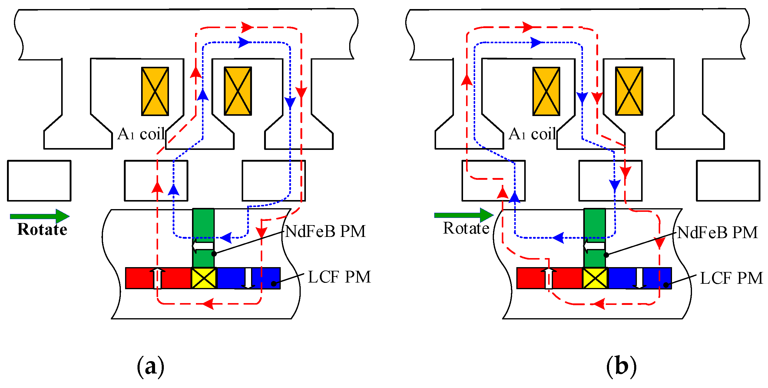
The working principle of the PS-SF-HMMM can be illustrated by using the variable flux characteristics of the LCF PMs [5]. Due to the nonlinear hysteresis characteristics, the LCF PMs can be repetitively magnetized by a magnetizing current pulse fed by the magnetizing windings. In fact, the spoke-type NdFeB PMs are magnetized tangentially and perform the flux-concentrating effect so as to improve the torque capability, whereas the LCF PMs are magnetized radially and behave in the same way as the flux adjustors. When the LCF PMs are bidirectionally magnetized via the magnetizing current, the magnetic fields induced by the NdFeB PM fields are either enhanced or weakened by LCF PM fields. Consequently, as illustrated in the open-circuit field distributions in Figure 1b, the air-gap flux can be flexibly adjusted. Actually, the transient torque and voltage ripples will be inevitably induced during the magnetization or demagnetization process. However, some control countermeasure can deal with this ripple issue, which will be reported in the further papers.
In addition, the switched-flux principle of the PS-SF-HMMM is essentially similar to that of the single stator one, as illustrated in Figure 2. The PM pole number is identical to that of the outer stator teeth, which allows switched flux action via alignment/misalignment between rotor segments and two separate stator parts.
3. Design Considerations
3.1. Hybrid Magnet Arrangement
First, the feasibility of hybrid PM types on the proposed PS-SF-HMMM is investigated in advance. The configurations and no-load field distribution of the machines having hybrid PMs with parallel and series circuits are shown in Figure 3. In order to ensure the rationality of the comparison, both the machines are equipped with a “U-shaped” PM type with same magnet usages. The only difference lies in the position of the LCF PM, which is surface-mounted for the series type, and interior-embedded for the parallel type. The distinct difference between field distributions of the parallel machine at the two states indicates its higher flux adjustable capability.
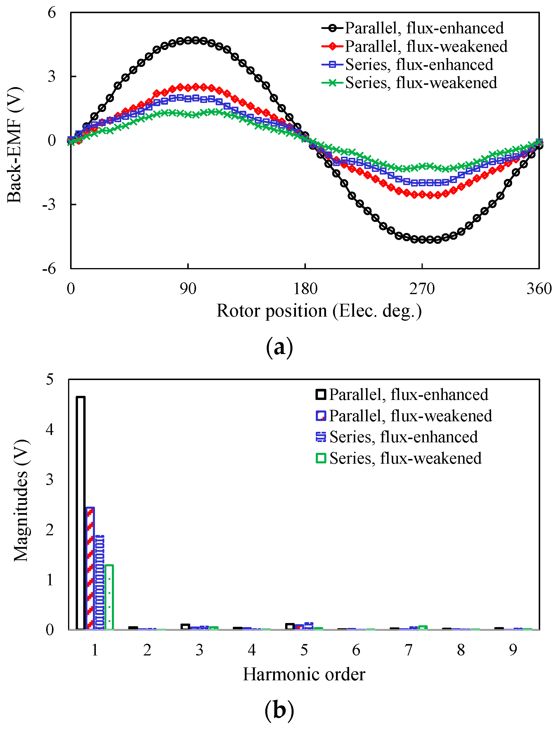
The back-EMF and torque-current characteristics of the two PS-SF-HMMMs under different magnetization states are compared as shown in Figure 4 based on the same peripheral parameters. It shows that the torque capability and flux regulation range of the parallel type significantly exceed those of the series type. This is mainly due to the large magnetic reluctance for the flux loop of the NdFeB PM that acts as the main contributor of air-gap flux in the “series” case. Therefore, the feasibility of the parallel magnetic circuit design is identified, and hence selected for the following investigation.
3.2. Feasible Stator-Slot/Rotor-Pole Combinations
Similar to the conventional SF machines [27,28,29], the PM pole-pair number Pm, rotor iron segment number Nr and pole-pair number of stator windings Ns must satisfy
On the other hand, in order to obtain the symmetrical phase flux linkage, the number of the phases Nph, Nr and Ns must satisfy [22]
where GCD is the greatest common divisor. The winding factor can be calculated by multiplying the distribution factor kd and pitch factor kp, which can be represented by [22]
where Q is the number of the least EMF phasors per phase, α is the electrical angle between two adjacent EMF phasors, and k is the number of harmonic order [22]. By way of example as a unit machine, the winding factors of the 6-stator-slot PS-SF-HMMM are tabulated in Table 1. It demonstrates that the maximum winding factor can be obtained when the rotor pole number is close to the multiples of 6, namely 5, 7, 11, 13, 17, and 19. These combinations are chosen for the subsequent parametric optimization. Then, due to the negligible saliency ratio, the sizing equation of PS-SF-HMMMs under brushless AC operation and zero d-axis current control can be given as
where Dso is the stator outer diameter (90 mm), la is the stack length (25 mm); Pout is the rated output power (~200 W), η is the efficiency, kl is the flux leakage factor, A is the electric loading (~200 A/cm), n is the rated speed (~400 r/min), αs is stator pole-arc coefficient, and Bgmax is the maximum air-gap flux density (~0.9 T) corresponding to the full magnetization level of Al-Ni-Co PMs. Once the basic performance requirement is given, the main design envelops Dso and la are predetermined.
3.3. Optimization of the Major Design Parameters
In this section, the geometric parameters of the 6-stator-slot PS-SF-HMMMs featuring “Nr = kNs ± 1” (k = 1, 2, 3) are globally optimized. The cross-sections and corresponding field distributions characterized by “Nr = kNs − 1” (k = 1, 2, 3) are shown Figure 5. It is apparent that the flux adjusting capabilities of machines with “Nr = Ns − 1” are the lowest owing to the localized magnetic saturation in the inner stator.
The design parameters are tabulated in Figure 6. JMAG 17.0 package is employed for FE simulation. It is worth noting that the copper loss is fixed to 30 W during the optimization approach. The global optimization [29] was performed to maximize average torque at the flux-enhanced state. Subsequently, the PM sizing was refined in order to satisfy the requirements of flux regulation range and unintentional demagnetization withstand capability. After the global optimization, the influences of individual parameters varying around the optimum ones on the torque were investigated in order to establish the general design guidelines for the PS-SF-HMMMs.
For simplicity, the optimization results for only parts of the leading design parameters are presented here. First, various design variables are defined as follows
where the split ratio λs can be defined as the ratio of Dsi to Dso; the slot-opening ratio λso is defined as the ratio of τso to τos; the outer/inner rotor pole ratios λro and λri are defined as the ratios of lr1/lr2 to τr. The globally optimized parameters of all the 6-stator-slot PS-SF-HMMMs with “Zr = kNs ± 1” (k = 1, 2, 3) are tabulated in Table 2.
3.3.1. Split Ratio
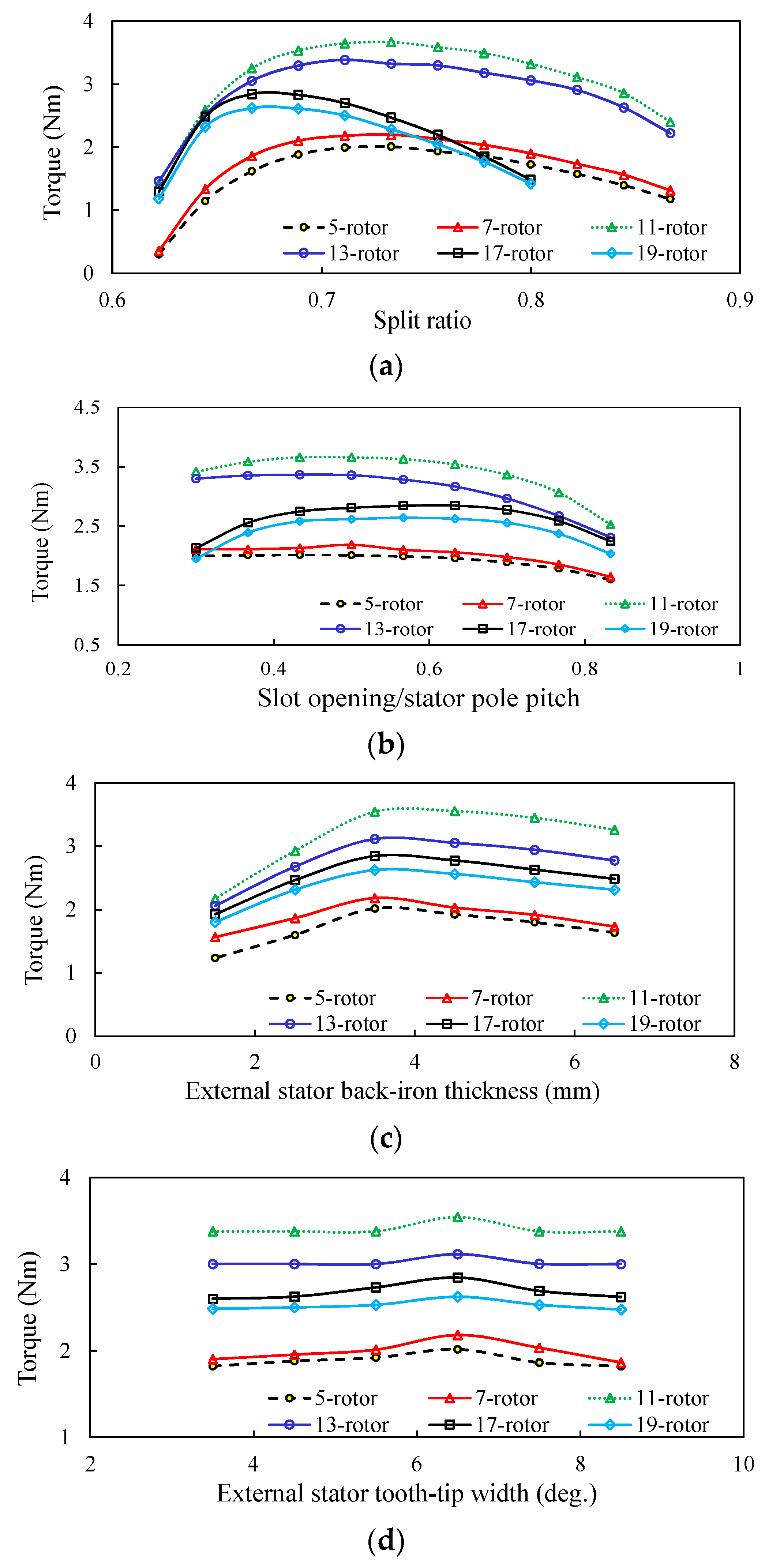
The average torque variation with the split ratio is illustrated in Figure 7a with fixed rated copper loss (30 W). It shows that the torque rises first, and then drops steadily. The torque rose as the PM area enlarged with the increase of the split ratio. However, as the split ratio is higher than the optimal value, the reduced armature area with increasing split ratio results in the torque decrease in turn. It can also be seen that the torque capability of the 11-rotor machine ranks first.
3.3.2. Stator Slot-Opening
Figure 7b depicts the variation of average torque with the slot opening ratio. It can be seen that the optimum slot-opening ratio decreases with the rotor iron segment number. This is due to the fact that the lower stator tooth width for the high rotor iron number cases reduces flux leaked by the adjacent rotor iron segments and stator tooth-tips. That is to say, the torque decreases significantly with the increase of the stator tooth width since the majority of the PM fluxes will be short circuited within the stator tooth part. Besides, the torque decreases dramatically with the increase of slot opening ratio since less flux effectively circulates through the outer stator teeth in those cases.
3.3.3. Outer Stator Back-Iron Thickness
The external stator back-iron thickness hbi was optimized as shown in Figure 7c. The fluctuation of torque indicates that the narrow hbi gave rise to the large magnetic reluctance for the main air-gap flux, while the over-wide hbi reduced the slot areas. It can be observed that the optimal hbi equals to 3.5 mm, regardless of the rotor pole numbers.
3.3.4. Outer Stator Tooth-Tip Width
The variation of torque with the external stator tooth-tip width ltip is shown in Figure 7d The slight fluctuation of torque profiles can be observed for all the cases. It demonstrates that the narrow ltip leads to the reduction of the effective PM fluxes penetrating through the stator, while the PM flux leakage increases as ltip exceeds the optimum value. It can be observed that the optimal ltip is equal to 6.5 degrees for all the machines with different rotor pole numbers.
3.3.5. Rotor Pole Ratios
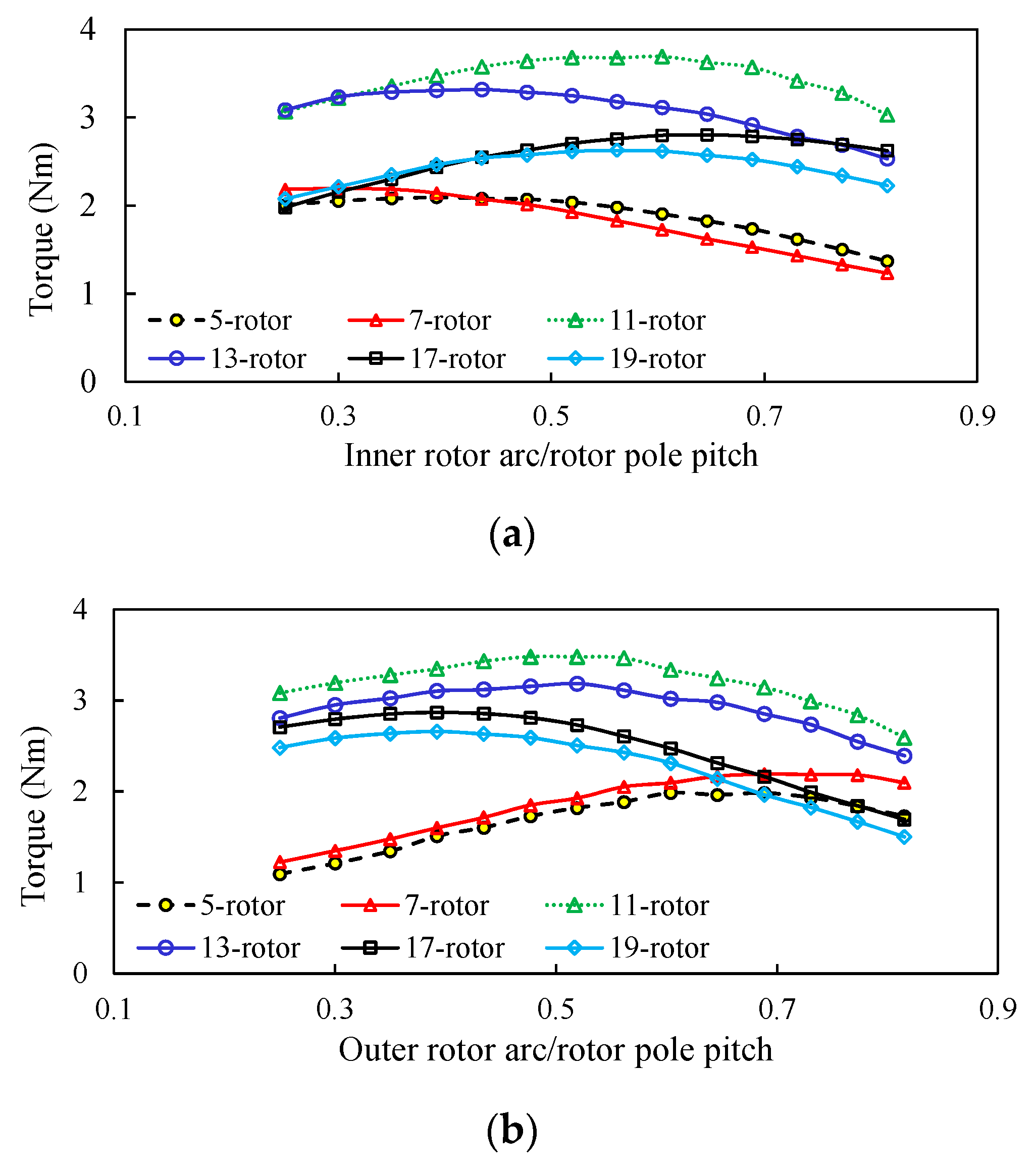
The influences of the inner or outer rotor pole ratios on the average torque are illustrated in Figure 8a,b respectively. The results indicate that the excessive rotor arches leads to the flux leakage, and consequently the torque capability is compromised. However, the effective flux linkage will descend as the rotor pole ratio drops to become lower than the optimum value.
3.3.6. Rotor Radial Thickness
The rotor radial thickness is optimized as shown in Figure 8c. The torque rises first radically within a certain range, and then drops gradually, which is due to the significant flux leakage within the rotor and inner stator parts when the rotor thickness exceeds the optimum values. Moreover, it can be visualized that the higher the rotor iron segment number, the lower the optimum rotor radial thickness, since a thicker rotor pole causes more flux leakage between two adjacent rotor iron segments for the high rotor number cases.
3.3.7. PM Dimensions
The dual magnet dimensions are further refined with the restriction of the other optimized parameters, as previously mentioned. The variations of torque and flux adjusting ratio with the magnet thickness and length are shown in Figure 9. It is worth mentioning that the flux adjusting ratio is defined as the ratio of phase flux linkages under the flux-enhanced and weakened states. It is obvious that the torque capability is more sensitive to magnet thickness rather than the magnet width, while the flux adjusting ratio rarely fluctuates with the variation of magnet thickness, which matches well with the preceding analyses. In addition, the flux adjusting ratio increases at first, and then drops drastically with the increase of LCF magnet width, which is attributed to the demagnetization occurring in the low LCF PM with lower widths. Whereas, the over-wide LCF PM width will lead to the magnetic saturation in the inner stator iron, and hence limiting the flux adjusting ability. Besides, the on-load demagnetization withstand capability of LCF PMs should be examined to get rid of the unexpected performance degradation. The unintentional demagnetization ratio (DR) due to the load effect can be defined as [22]
where ψ1 and ψ2 are the phase flux linkages of the machine before and after q-axis current excitation (40A). Figure 9c shows the variation of DR with the PM dimensions. It can be seen that the LCF thickness and width (3 mm/15 degree) can achieve the satisfactory trade-off. As a result, the flowchart of the overall design procedure is shown in Figure 10, which mainly includes the parameter initialization, the magnet arrangement design, parameter optimization and LCF PM sizing refinement, etc. If the predicted performances and specifications do not match very well, the fixed value of the parameters at the start of this design should be refined until they match well with each other. This process may take several iterative loops to get satisfactory results. FEM was employed to check the analysis results of the preliminary design stage.
The torque capability of the optimized 6-stator-slot PS-SF-HMMMs with various rotor pole pieces is analyzed and compared in Figure 11. Although the operating frequency of the machines satisfying “Nr = 3Ns + 1” is higher, they still produce lower average torque than those satisfying “Nr = 2Ns + 1”, which can be attributed to the significant flux leakage, as evidenced in Figure 5. In addition, it demonstrates that the machines with “Nr = 11” have highest torque capability, which was selected for the prototype manufacturing.
4. Experimental Validation
An optimized 6-stator slot/11-rotor pole prototype is fabricated for experimental validations to verify the preceding analyses. The prototypes and test platform are shown in Figure 12. The open-circuit phase back-EMFs for the 6-stator slot/11-rotor pole machine subject to various MSs have been measured and compared with FE predictions as shown in Figure 13a. Meanwhile, the measured and FE-simulated torques versus rotor position and q-axis current characteristics are demonstrated in Figure 13b,c, respectively. It can be founded that a slight mismatch between 2-D FE predictions and measurements exists, because end-effect and mechanical tolerance are not considered in the 2-D FE simulation [30,31,32]. Hence, the three-dimensional (3-D) FE method is conducted, and the relative errors between FE and measured results are tabulated in Table 3. It can be observed that the error increases with the reduction of magnetization state of LCF PMs, which is mainly attributed to more severe fraction and mechanical tolerances at the flux-weakened state [33,34,35,36]. Overall, good agreement can be obtained between 3D-FE predictions and experimental measurements. Thus, the validity of the theoretical analyses was verified.
5. Conclusions
In this paper, the general design considerations of the PS-SF-HMMM were analyzed. In the proposed PS-SF-HMMM, the design of PM and armature windings on the two separate stators allows the torque improvement over its single-stator counterpart. The feasibility of hybrid magnet arrangements was investigated in advance. The results show that the parallel magnetic circuit type is preferable due to its higher torque capability and flux adjusting performance. In addition, the stator slot/rotor pole number combination and various design parameters were optimized. It can be found that the machines with “Nr = 2Ns ± 1” exhibit the highest torque. The design guideline for PM sizing was also provided, which aims to achieve better balanced torque capability, flux adjusting range, as well as the unintentional demagnetization withstand ability. Finally, a 6-stator slot/11-rotor pole prototype was fabricated to experimentally validate the feasibility of the design approach.
Author Contributions
Conceptualization, J.L. and H.Y.; Methodology, H.Y.; Software, C.W.; Validation, H.Z. and W.W.; Formal Analysis, J.L.; Investigation, S.F.; Resources, J.L. and H.Y.; Data Curation, C.W.; Writing-Original Draft Preparation, J.L. and H.Z.; Writing-Review & Editing, H.Y. and S.F.; Visualization, W.W.; Supervision, J.L. and H.Y.; Project Administration, J.L. and H.Y.; Funding Acquisition, J.L. and H.Y.
Funding
This work was jointly supported in part by National Natural Science Foundations of China under Grant 51707036, in part by Natural Science Foundation of Jiangsu Province for Youth (BK20170674 and BK20180396), in part by the Fundamental Research Funds for the Central Universities (2242017K41003), in part by “Hong Kong Scholar” Program (XJ2018014), in part by Supported by the “SEU Zhishan scholars” Program of Southeast University (2242019R40042), and in part by the Scientific Research Foundation of Graduate School of Southeast University.
Conflicts of Interest
The authors declare no conflict of interest.
References
- Yang, H.; Zhu, Z.Q.; Lin, H. Flux adjustable permanent magnet machines: A technology status review. Chin. J. Electr. Eng. 2016, 2, 14–30. [Google Scholar] [CrossRef]
- Mudhigollam, U.K.; Choudhury, U.; Hatua, K. Wide regulated series hybrid excitation alternator. IET Electr. Power Appl. 2018, 12, 439–446. [Google Scholar] [CrossRef]
- Pothi, N.; Zhu, Z.Q.; Afinowi, I.A.A. Control strategy for hybrid-excited switched-flux permanent magnet machines. IET Electr. Power Appl. 2015, 9, 612–619. [Google Scholar] [CrossRef]
- Zhu, Z.Q.; Al-Ani, M.M.J.; Liu, X. A mechanical flux weakening method for switched flux permanent magnet machines. IEEE Trans. Energy Convers. 2015, 30, 806–815. [Google Scholar] [CrossRef]
- Ostovic, V. Memory motors. IEEE Ind. Appl. Mag. 2003, 9, 52–61. [Google Scholar] [CrossRef]
- Sakai, K.; Hagiwara, K.; Hirano, Y. High-power and high-efficiency permanent-magnet reluctance motor for hybrid electric vehicle. Toshiba Rev. 2005, 60, 41–44. [Google Scholar]
- Maekawa, S.; Yuki, K.; Matsushita, M. Study of the magnetization method suitable for fractional-slot concentrated-winding variable magnetomotive-force memory motor. IEEE Trans. Power Electron. 2014, 29, 4877–4887. [Google Scholar] [CrossRef]
- Limsuwan, N.; Kato, T.; Akatsu, K. Design and evaluation of a variable-flux flux-intensifying interior PM machine. IEEE Trans. Ind. Appl. 2014, 50, 1015–1024. [Google Scholar] [CrossRef]
- Athavale, A.; Erato, D.J.; Lorenz, R. Enabling driving cycle loss reduction in variable flux PMSMs via closed-loop magnetization state control. IEEE Trans. Ind. Appl. 2018, 54, 3350–3359. [Google Scholar] [CrossRef]
- Gagas, B.S.; Sasaki, K.; Athavale, A. Magnet temperature effects on the useful properties of variable flux PM synchronous machines and a mitigating method for magnetization changes. IEEE Trans. Ind. Appl. 2017, 53, 2189–2199. [Google Scholar] [CrossRef]
- Thike, R.; Pillay, P. Characterization of a variable flux machine for transportation using a vector controlled drive. IEEE Trans. Transp. Electrif. 2018, 4, 494–505. [Google Scholar] [CrossRef]
- Ibrahim, M.; Masisi, L.; Pillay, P. Design of variable flux PM machine for reduced inverter rating. IEEE Trans. Ind. Appl. 2014, 51, 3666–3674. [Google Scholar] [CrossRef]
- Ajehaimi, A.M.; Pillay, P. Operating envelopes of the variable flux machine with positive reluctance torque. IEEE Trans. Transp. Electrif. 2018, 4, 707–719. [Google Scholar] [CrossRef]
- Zhou, Y.; Chen, Y.; Shen, J. Analysis and improvement of a hybrid permanent-magnet memory motor. IEEE Trans. Energy Concers. 2016, 31, 915–923. [Google Scholar] [CrossRef]
- Yu, C.; Chau, K.T. Design, analysis, and control of DC-excited memory motors. IEEE Trans. Energy Convers. 2011, 26, 479–489. [Google Scholar] [CrossRef]
- Wang, Q.; Niu, S.; Ho, S.L. Design and analysis of novel magnetic flux-modulated mnemonic machines. IET Electr. Power Appl. 2015, 9, 467–477. [Google Scholar] [CrossRef]
- Zhu, X.; Quan, L.; Chen, D. Design and analysis of a new flux memory doubly salient motor capable of online flux control. IEEE Trans. Magn. 2011, 47, 3220–3223. [Google Scholar] [CrossRef]
- Yang, H.; Lin, H.; Zhuang, E. Investigation of design methodology for non-rare-earth variable-flux switched flux memory machines. IET Electr. Power Appl. 2016, 10, 744–756. [Google Scholar] [CrossRef]
- Wu, D.; Liu, X.; Zhu, Z.Q. Switched flux hybrid magnet memory machine. IET Electr. Power Appl. 2015, 9, 160–170. [Google Scholar] [CrossRef]
- Yang, H.; Zhu, Z.Q.; Lin, H. Comparative study of novel variable-flux memory machines having stator permanent magnet topologies. IEEE Trans. Magn. 2015, 51, 1–4. [Google Scholar] [CrossRef]
- Yang, H.; Zhu, Z.Q.; Lin, H. Synthesis of hybrid magnet memory machines having separate stators for traction applications. IEEE Trans. Veh. Technol. 2018, 67, 183–195. [Google Scholar] [CrossRef]
- Yang, H.; Zhu, Z.Q.; Lin, H. Comparative study of hybrid PM memory machines having single- and dual-stator configurations. IEEE Trans. Ind. Electron. 2018, 65, 9168–9178. [Google Scholar] [CrossRef]
- Yang, H.; Zhu, Z.Q.; Lin, H. Performance improvement of partitioned stator switched flux memory machines with triple-magnet configuration. IEEE Trans. Magn. 2016, 52, 1–4. [Google Scholar] [CrossRef]
- Zhu, Z.Q. Overview of novel magnetically geared machines with partitioned stators. IET Electr. Power Appl. 2018, 12, 595–604. [Google Scholar] [CrossRef]
- Evans, D.; Zhu, Z.Q. Novel partitioned stator switched flux permanent magnet machines. IEEE Trans. Magn. 2014, 51, 1–4. [Google Scholar] [CrossRef]
- Wu, Z.Z.; Zhu, Z.Q. Analysis of magnetic gearing effect in partitioned stator switched flux PM machines. IEEE Trans. Energy Convers. 2016, 31, 1239–1249. [Google Scholar] [CrossRef]
- Chu, W.Q.; Zhu, Z.Q.; Zhang, J. Investigation on operational envelopes and efficiency maps of electrically excited machines for electric vehicle applications. IEEE Trans. Magn. 2015, 51, 1–10. [Google Scholar] [CrossRef]
- Hua, H.; Zhu, Z.Q.; Wang, C. Partitioned stator machines with NdFeB and ferrite magnets. IEEE Trans. Ind. Appl. 2017, 53, 1870–1882. [Google Scholar] [CrossRef]
- Chen, J.T.; Zhu, Z.Q. Winding configurations and optimal stator and rotor pole combination of flux-switching PM brushless AC machines. IEEE Trans. Energy Convers. 2010, 25, 293–302. [Google Scholar] [CrossRef]
- Zhu, Z.Q.; Liu, X. Individual and global optimization of switched flux permanent magnet motors. In Proceedings of the 2011 International Conference on Electrical Machines and Systems, Beijing, China, 20–23 August 2011. [Google Scholar]
- Mercorelli, P. An adaptive and optimized switching observer for sensorless control of an electromagnetic valve actuator in camless internal combustion engines. Asian J. Control 2014, 16, 959–973. [Google Scholar] [CrossRef]
- Braune, S.; Liu, S.; Mercorelli, P. Design and control of an electromagnetic valve actuator. In Proceedings of the 2006 IEEE Conference on Computer Aided Control System Design, 2006 IEEE International Conference on Control Applications, 2006 IEEE International Symposium on Intelligent Control, Munich, Germany, 4–6 October 2006; pp. 1657–1662. [Google Scholar]
- Zhu, X.; Huang, J.; Quan, L.; Xiang, Z.; Shi, B. Comprehensive sensitivity analysis and multi-objective optimization research of permanent magnet flux-intensifying motors. IEEE Trans. Ind. Electron. 2019, 66, 2613–2627. [Google Scholar] [CrossRef]
- Zhu, X.; Fan, D.; Xiang, Z.; Quan, L.; Hua, W.; Cheng, M. Systematic multi-level optimization design and dynamic control of less-rare-earth hybrid permanent magnet motor for all-climatic electric vehicles. Appl. Energy 2019, 253, 113549. [Google Scholar] [CrossRef]
- Zhu, X.; Jiang, M.; Xiang, Z.; Quan, L.; Hua, W.; Cheng, M. Design and optimization of a flux-modulated permanent magnet motor based on an airgap-harmonic-orientated design methodology. IEEE Trans. Ind. Electron. 2019. [Google Scholar] [CrossRef]
- Zhu, X.; Wu, W.; Quan, L.; Xiang, Z.; Gu, W. Design and multi-objective stratified optimization of a less-rare-earth hybrid permanent magnets motor with high torque density and low cost. IEEE Trans. Energy Convers. 2019, 34, 1178–1189. [Google Scholar] [CrossRef]
Figure 1.
Proposed partitioned stator switched flux hybrid magnet memory machine (PS-SF-HMMM). (a) Configuration; (b) Operating principle.
Figure 1.
Proposed partitioned stator switched flux hybrid magnet memory machine (PS-SF-HMMM). (a) Configuration; (b) Operating principle.

Figure 2.
Switched-flux principle of proposed PS-SF-HMMM. (a) Rotor position A; (b) Rotor position B.
Figure 2.
Switched-flux principle of proposed PS-SF-HMMM. (a) Rotor position A; (b) Rotor position B.

Figure 3.
Configurations and flux regulation principle of PS-SF-HMMMs with parallel and series magnetic circuits. (a) Parallel; (b) Series.
Figure 3.
Configurations and flux regulation principle of PS-SF-HMMMs with parallel and series magnetic circuits. (a) Parallel; (b) Series.

Figure 4.
Key electromagnetic characteristics of PS-SF-HMMMs with parallel and series magnetic circuits. (a) Open-circuit EMF waveforms; (b) EMF harmonic spectra; (c) Torque-current curves.
Figure 4.
Key electromagnetic characteristics of PS-SF-HMMMs with parallel and series magnetic circuits. (a) Open-circuit EMF waveforms; (b) EMF harmonic spectra; (c) Torque-current curves.


Figure 5.
Topologies and field plots of the 6-stator slot machines having various selected rotor pole numbers. (a) 5-rotor; (b) 11-rotor; (c) 17-rotor.
Figure 5.
Topologies and field plots of the 6-stator slot machines having various selected rotor pole numbers. (a) 5-rotor; (b) 11-rotor; (c) 17-rotor.

Figure 6.
Illustration of design parameters of PS-SF-HMMM.

Figure 7.
Variation of average torque with various stator design parameters, Id = 0, copper loss = 30 W. (a) Split ratio; (b) Slot opening ratio; (c) Outer stator back-iron thickness; (d) Outer stator tooth-tip width.
Figure 7.
Variation of average torque with various stator design parameters, Id = 0, copper loss = 30 W. (a) Split ratio; (b) Slot opening ratio; (c) Outer stator back-iron thickness; (d) Outer stator tooth-tip width.

Figure 8.
Variation of average torque with various rotor design parameters, Id = 0, copper loss = 30 W. (a) Inner rotor pole ratio; (b) Outer rotor pole ratio; (c) Rotor radial thickness.
Figure 8.
Variation of average torque with various rotor design parameters, Id = 0, copper loss = 30 W. (a) Inner rotor pole ratio; (b) Outer rotor pole ratio; (c) Rotor radial thickness.


Figure 9.
Variations of key electromagnetic characteristics with various PM dimensions, Id = 0, copper loss = 30 W. (a) Torque; (b) Flux adjusting ratio; (c) Demagnetization ratio.
Figure 9.
Variations of key electromagnetic characteristics with various PM dimensions, Id = 0, copper loss = 30 W. (a) Torque; (b) Flux adjusting ratio; (c) Demagnetization ratio.

Figure 10.
The overall design flowchart of the PS-SF-HMMM.

Figure 11.
FE-predicted normalized torque of 6-stator-slot PS-SF-HMMMs with respect to rotor pole numbers.
Figure 11.
FE-predicted normalized torque of 6-stator-slot PS-SF-HMMMs with respect to rotor pole numbers.

Figure 12.
The manufactured prototype of the 6-slot slot/11-pole PS-SF-HMMM. (a) Prototype; (b) Test rig.
Figure 12.
The manufactured prototype of the 6-slot slot/11-pole PS-SF-HMMM. (a) Prototype; (b) Test rig.

Figure 13.
Comparison of finite element (FE)-predicted and measured results. (a) Back-EMF; (b) Static torque; (c) Torque against current characteristics.
Figure 13.
Comparison of finite element (FE)-predicted and measured results. (a) Back-EMF; (b) Static torque; (c) Torque against current characteristics.


Table 1.
Winding Factors of 6-Stator-Slot PS-SF-HMMM with Different Rotor Pole Numbers.
| Nr | 4 | 5 | 7 | 8 | 10 | 11 |
| kd | 1 | 1 | 1 | 1 | 1 | 1 |
| kp | 0.5 | 0.87 | 0.87 | 0.87 | 0.5 | 0.87 |
| kw | 0.5 | 0.87 | 0.87 | 0.87 | 0.5 | 0.87 |
| Nr | 13 | 14 | 16 | 17 | 19 | 20 |
| kd | 1 | 1 | 1 | 1 | 1 | 1 |
| kp | 0.87 | 0.87 | 0.5 | 0.87 | 0.87 | 0.5 |
| kw | 0.5 | 0.87 | 0.87 | 0.87 | 0.5 | 0.87 |
Table 2.
Design Specifications of the 6-Stator-Slot PS-SF-HMMMs.
| Items | Parameters | ||
|---|---|---|---|
| Stator slot/rotor pole number | 5/7 | 11/13 | 17/19 |
| Outer stator diameter (mm), Dso | 90 | ||
| Inner diameter of outer stator (mm), Dsi | 63 | 67 | 68 |
| Outer stator tooth width (degree), bst | 16 | 12.5 | 12.5 |
| Outer stator opening width (degree), τos | 43 | 46 | 48 |
| Outer diameter of inner stator (mm), Dis | 53.5 | 57 | 59 |
| Air-gap length (mm), go/gi | 0.5 | ||
| Arc of outer rotor edge (deg.), lr1 | 30/26 | 16/18 | 11/10 |
| Arc of inner rotor edge (deg.), lr2 | 30/25 | 16/18 | 12/11 |
| Rotor thickness (mm), hr | 5.5 | 5.0 | 4.5 |
| Active stack length (mm), lef | 25 | ||
| LCF PM thickness×length (mm), hm1 × lm1 | 4/12 | 3/12 | 3/12 |
| NdFeB thickness×length (mm), hm2 × lm2 | 1.7/8 | 1.5/8 | 1.5/8 |
| Rated speed (r/min) | 400 | ||
| PM volume (cm3) | 19.7 | 18.2 | 16.9 |
| Number of phase armature windings | 84 | ||
| Number of magnetizing windings per coil | 100 | ||
Table 3.
Relative Errors between FE and Measured Results of PS-SF-HMMMs.
| Items | 2D FE | 3D FE | Measured | Error (%, 2D/3D) |
|---|---|---|---|---|
| Fundamental EMF @ Flux-enhanced | 3.24 | 2.98 | 2.82 | 14.89/5.67 |
| Fundamental EMF @ Flux-weakened | 0.93 | 0.84 | 0.79 | 17.72/6.33 |
| Rated-load average torque @ Flux-enhanced | 1.88 | 1.75 | 1.68 | 11.90/4.17 |
| Rated-load average torque @ Flux-weakened | 0.55 | 0.50 | 0.42 | 23.63/19.05 |
© 2019 by the authors. Licensee MDPI, Basel, Switzerland. This article is an open access article distributed under the terms and conditions of the Creative Commons Attribution (CC BY) license (http://creativecommons.org/licenses/by/4.0/).
Share and Cite
MDPI and ACS Style
Lei, J.; Wei, C.; Yang, H.; Zheng, H.; Wang, W.; Feng, S. Design Considerations of Switched Flux Memory Machine with Partitioned Stators. Energies 2019, 12, 3868. https://0-doi-org.brum.beds.ac.uk/10.3390/en12203868
AMA Style
Lei J, Wei C, Yang H, Zheng H, Wang W, Feng S. Design Considerations of Switched Flux Memory Machine with Partitioned Stators. Energies. 2019; 12(20):3868. https://0-doi-org.brum.beds.ac.uk/10.3390/en12203868
Chicago/Turabian StyleLei, Jiaxing, Chaofan Wei, Hui Yang, Hao Zheng, Wenjia Wang, and Shuang Feng. 2019. "Design Considerations of Switched Flux Memory Machine with Partitioned Stators" Energies 12, no. 20: 3868. https://0-doi-org.brum.beds.ac.uk/10.3390/en12203868
Note that from the first issue of 2016, this journal uses article numbers instead of page numbers. See further details here.