Article

Control Strategy of Intergrated Photovoltaic-UPQC System for DC-Bus Voltage Stability and Voltage Sags Compensation

1
College of Information Science and Engineering, Northeastern University, Shenyang 110819, China
2
State Grid Shenyang Electric Power Supply Company, Shenyang 110811, China; zhuang [email protected]
*
Author to whom correspondence should be addressed.
Submission received: 20 September 2019 / Revised: 16 October 2019 / Accepted: 17 October 2019 / Published: 22 October 2019

Abstract

:
Power quality problem, because of its various forms and occurrence frequency, has become one of the most critical challenges confronted by a power system. Meanwhile, the development of renewable energy has led to more demands for an integrated system that combines both merits of sustainable energy generation and power quality improvement. In this context, this paper discusses an integrated photovoltaic-unified power quality conditioner (PV-UPQC) and its control strategy. The system is composed of a series compensator, shunt compensator, dc-bus, and photovoltaic array, which conducts an integration of photovoltaic generation and power quality mitigation. The fuzzy adaptive PI controller and the improved Maximum Power Point Tracking (MPPT) technique are proposed to enhance the stability of dc-bus voltage, which is aimed at the power balance and steady operation of the whole system. Additionally, the coordinate control strategy is studied in order to ensure the normal operation and compensation performance of the system under severe voltage sag condition. In comparison to the existing PV-UPQC system, the proposed control method could improve the performance of dc-bus stability and the compensation ability. The dynamic behavior of the integrated system were verified by simulation in MATLAB and PLECS. Selected results are reported to show that the dc-bus voltage was stable and increased under severe situations, which validates the effectiveness of the proposed integrated PV-UPQC system and its control strategy.

Graphical Abstract

1. Introduction

The electrification revolution that began in the last century has made profound achievements with electric energy becoming the highest efficient form of end-use energy widely applied in every field of modern society [1]. Accordingly, power quality (PQ) plays an increasingly significant role in the economy, security, and user experience of industrial, commercial, and residential consumers [2,3]. Compared with the traditional electrical load, a new generation of load equipment controlled by a microprocessor and power electronic device is much more sensitive to fluctuations in power distribution system, leading to great concerns and stringent requirements of power quality [4].
Normally, power quality issues can be divided into two main aspects, namely voltage and current quality [5], including the phenomena of voltage sag, voltage swell, harmonic current, and current ripple [6]. Thus various equipment as well as its control technique for power quality improvement, such as active power filter (APF) [7], static var compensator (SVC) [8], static var generator (SVG) [9], static synchronous compensator (STATCOM) [10], dynamic voltage restorer (DVR) [11], and uninterruptible power supply (UPS) [12], has been proposed and discussed in the previous published literature.
Furthermore, the significant growth in the penetration level of sustainable energy imposes new challenges to power quality regulations in a power system. For example, a grid-connected photovoltaic (PV) generation system leads to several power quality issues such as harmonic, voltage sags, voltage swells, and frequency quality problems due to the intermittent nature and reactive compensation topology [13], which destabilizes the power grid ultimately. In such cases, some researchers have discussed the possibility of integrating the functionality of PV and APF for harmonic cancellation and reactive power compensation [14,15]. In [16] a soft computing method is analyzed for a PV system with a reactive power compensation function of APF. The authors in [17] focus on the harmonic compensation function of APF integrating with a PV system to filter the current harmonic. As for voltage quality, it has already been reported that it is possible to integrate DVR into a PV system [18]. The authors in [19] discuss the application of an integrated PV and DVR system in the distribution network. Article [20] devises a control method to coordinate the compensating process of the PV-based DVR. Article [21] proposes a PV-based DVR using fuzzy logic controller to ensure normal operation in the case of a short interruption.
Nevertheless, the abovementioned equipment commonly concentrates on a certain kind of power quality issue. When it comes to improvement requests for various poor power quality, tough problems are being encountered owing to the multiple installed voltage and current conditioners, for instance, reduplicative compensation, interaction effect, and lack of coordination control. Meanwhile, an excess of conditioning devices are inclined to decrease the power quality level because of the nature of power electronic devices. Additionally, a higher penetration of renewable energy brings more challenges to power quality as well as new opportunities. In this context, many researchers dedicate to the study of unified power quality conditioner (UPQC) [22,23,24], an integrated equipment combined with series and shunt APFs to simultaneously achieve superior mitigation over most current and voltage imperfections. Thus a significant improvement was done presenting the combination with UPQC and distributed generation in [25], which deals with the problems of voltage sags/swells, short interruptions, harmonic, and reactive power. In this way, the power angle control method for PV-UPQC topology has been studied in [26,27]. A control approach of a single-phase two-stage PV-UPQC has been proposed in [28], which depends on the second-order generalized integrator and delayed signal cancellation. A kind of three-phase solar PV-UPQC topology has been designed and analyzed in [29]. The authors in [30] address the modeling, analysis, and simulation of three-phase PV-UPQC, while in reference [31], the authors pay attention to deal with distorted current and voltage conditions using PV-UPQC.
However, the attempt to integrate UPQC into a solar photovaltaic system is still at an early stage although this research field has been on the momentum of development and prosperity, and there are still some problems demanding a prompt solution. For instance, the stable control issue of dc-bus voltage, which is closely related to the PV array output power from the point of photovoltaic generation and the compensation effect from the perspective of power quality regulation. Most existing literature pay more attention to the model and control of series and shunt compensators [32,33,34], with a lack of discussion on the schemes for dc-bus voltage stability under solar irradiance fluctuation and grid disturbances. Recently, some researchers have been gradually paying attention to the dc-bus voltage regulation. The authors in [35,36] utilize a PI controller to stabilize the total dc-bus voltage. The authors in [37] design the dc-link voltage controller based on sliding-mode control. These results provide good guidance to solve the dc-bus voltage issue, but it is still hard to give consideration to both robust performance and dynamic response characteristic. In addition, the compensation control strategy under severe voltage sags is another problem that demands a prompt solution. In a word, the dc-bus voltage stability and the control method in a severe power quality environment urgently need to be solved. Therefore, this manuscript attempts to study the control of dc-bus voltage in order to reduce oscillation and increase the accelerate power balance of the PV-UPQC system, when the external conditions change, especially for photovoltaic power sudden variation. Additionally, this paper focuses on limiting the active current under circumstance of severe voltage sags so as to increase the mitigation capacity of voltage sags to a certain extent.
In this work, the main contributions of this manuscript are as follows:
(1)
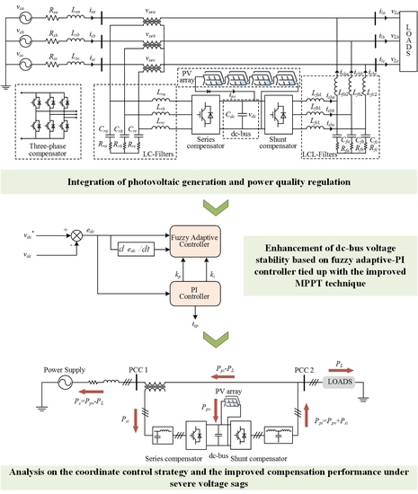
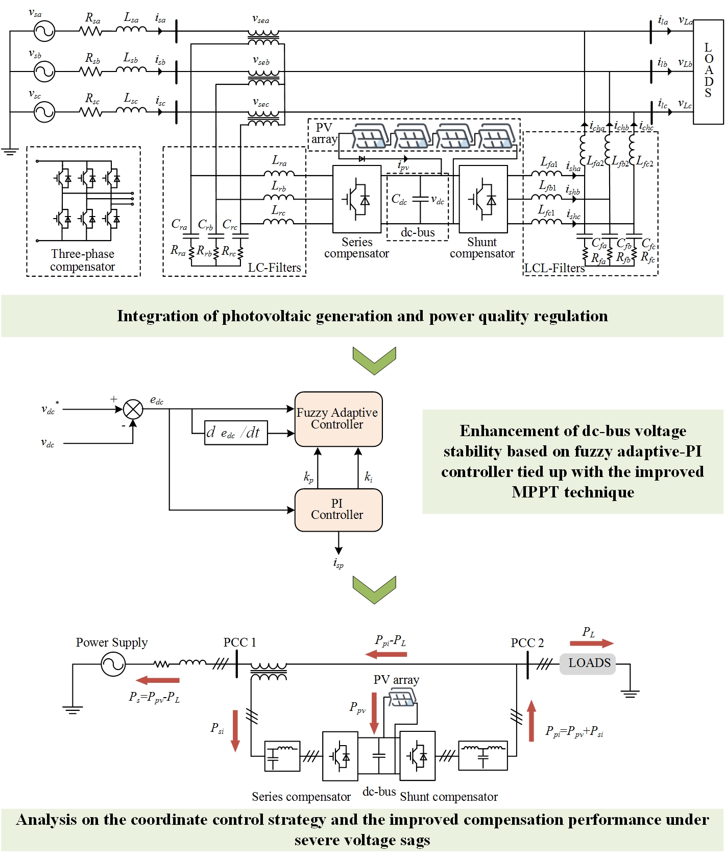
Integration of photovoltaic generation and power quality regulation;
(2)
Enhancement of dc-bus voltage stability based on fuzzy adaptive PI controller tied up with the improved Maximum Power Point Tracking (MPPT) technique;
(3)
Analysis on the coordinate control strategy and the improved compensation performance under severe voltage sags.
This paper is organized as follows. Section 2 presents the configuration and description of the proposed PV-UPQC system. Section 3 deals with the control strategy of the integrated PV-UPQC system, including the control of a series compensator, shunt compensator, and most importantly, the regulation of dc-bus voltage. Section 4 describes the coordination control strategy under severe voltage sags depending on UPQC integrated with solar photovoltaic. In Section 5, the simulation results are shown to illustrate the effectiveness of the proposed system and its control strategy. Finally, Section 6 concludes this paper.

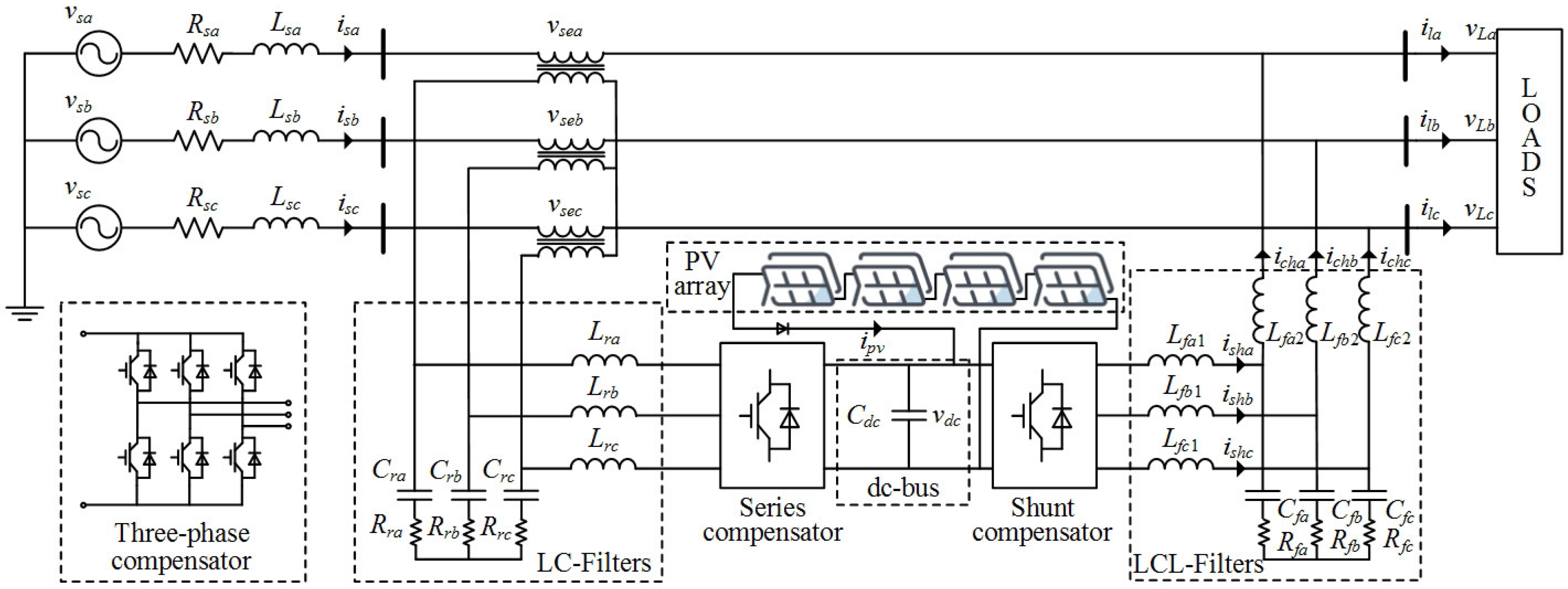
2. Configuration and Description

The topology of the proposed PV-UPQC system is composed of four parts, namely, the series compensator, shunt compensator, dc-bus, and photovoltaic array, as shown in Figure 1. The series compensator consists of inverters, LC-filters, and transformers connecting to the grid in a series and is supposed to discuss voltage quality problems such as voltage sags and swells. The shunt compensator, which is composed of inverters and LCL-filters, connects to the load side in parallel. It is used to suppress current power quality problems like decreasing the serious harmonic and reactive power pollution to the grid. The shunt compensator is also supposed to extract active power from photovoltaic panels to realize the function of the photovoltaic generation system. The series and shunt compensator are joint to a common dc-bus and the dc-link capacitor is employed as a power energy buffer. The photovoltaic array, of course, is used to provide active power to the load or the grid for achieving the function of the photovoltaic generation system.

2.1. Mathematical Description of the Compensators

In order to obtain the mathematical model of the series and shunt compensator, it is assumed that the inductors of the LC-filter and LCL-filter are equal to each other as well as the capacitors, that is, the inductances are L r a = L r b = L r c and the capacitances are C r a = C r b = C r c . Similarly, L f a 1 = L f b 1 = L f c 1 , L f a 2 = L f b 2 = L f c 2 , and their respective capacitances C f a = C f b = C f c . In addition, it is also assumed that no three phase unbalance phenomenon occurs because the amplitude unbalance has no material impact to dq-transform and the severe phase angle unbalance is almost impossible to occur in practical instances. Thus, by means of the series compensator scheme shown in Figure 1, the equation can be obtained as follows:
v L r _ a b c = v C r _ a b c v s i _ a b c i C r _ a b c = 1 n i s _ a b c i L r _ a b c
where v L r _ a b c and v C r _ a b c represent the voltages of inductors L r and capacitors C r respectively; while i C r _ a b c and i L r _ a b c are the currents flowing through capacitors C r and inductors L r respectively; i s _ a b c are grid currents; and n is the transformation ratio. After dq-transform, the equivalent mathematical model of series compensator can be written as:
x ˙ s i _ d q ( t ) = A s i x s i _ d q ( t ) + B s i u s i _ d q ( t )
where,
x ˙ s i _ d q ( t ) = [ d i L r d d t d i L r q d t d v C r d d t d v C r q d t ] T x s i _ d q ( t ) = [ i L r d i L r q v C r d v C r q ] T u s i _ d q ( t ) = [ i s d i s q v s i d v s i q ] T A s i = 0 ω 1 L r 0 ω 0 0 ω 1 C r 0 0 ω 0 1 C r ω 0 , B s i = 0 0 1 L r 0 0 0 0 1 L r 1 n C r 0 0 0 0 1 n C r 0 0
Considering the shunt compensator scheme shown in Figure 1 as well, the equations can be written as follows:
v L f 1 _ a b c = v C f _ a b c v p i _ a b c v L f 2 _ a b c = v L _ a b c v C f _ a b c i C f 2 _ a b c = v c h _ a b c i s h _ a b c
where v L f 1 _ a b c , v L f 2 _ a b c , and v C f _ a b c denote the voltages across L f 1 , L f 2 , and C f respectively; while i s h _ a b c , i c h _ a b c , and i C f _ a b c represent the currents flowing through L f 1 , L f 2 , and C f respectively; v L _ a b c denote load voltages, and v p i _ a b c are output voltages of the inverter. The mathematical model of shunt compensator can be represented in the dq-axis as well, and the state-space equation can be given as:
x ˙ p i _ d q ( t ) = A p i x p i _ d q ( t ) + B p i u p i _ d q ( t )
where,
x ˙ p i _ d q ( t ) = d i s h d d t d i s h q d t d i c h d d t d i c h q d t d v C f d d t d v C f q d t T x p i _ d q ( t ) = i s h d i s h q i c h d i c h q v C f d v C f q T u p i _ d q ( t ) = v p i d v p i q v L d v L q 0 0 T
A p i = 0 ω 0 0 1 L f 1 0 ω 0 0 0 0 1 L f 1 0 0 0 ω 1 L f 2 0 0 0 ω 0 0 1 L f 2 1 C f 0 1 C f 0 0 ω 0 1 C f 0 1 C f ω 0 ; B p i = 1 L f 1 0 0 0 0 0 0 1 L f 1 0 0 0 0 1 L f 2 0 0 0 0 0 0 1 L f 2 0 0 0 0 0 0 0 0 0 0 0 0 0 0 0 0

2.2. Parameter Design of the Compensators

For the series compensator, the value of the filter inductor depends on the switching frequency of the inverter, dc-bus voltage, and the ripple current. Thus its value can be expressed as:
L r = 3 × m × v d c × n 12 a f s i i r
where m represents the modulation depth, a denotes overload capacity, n is the ratio of the series transformer, f s i represents the switching frequency, and i r is the inductor current ripple. Here, m = 1 , n = 1 , a = 1.5 , f s i = 10  kHz, and i r is taken to be 20% of the grid current. Accordingly, L r = 1  mH, C r = 80 μ F, and R r = 10 Ω are selected as the value of LC-filter of the series compensator.
As for the shunt compensator, in order to reduce the resonant peak for stable operation, R f is connected in series in the capacitor branch. On the basis of design philosophy of the LCL-filter, one gets L f 1 = 1 mH, L f 2 = 0.2 mH, C f = 45 μ F, and R f = 0.6 Ω as the selected value.

3. Control of the PV-UPQC

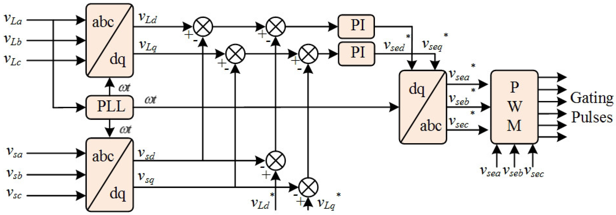
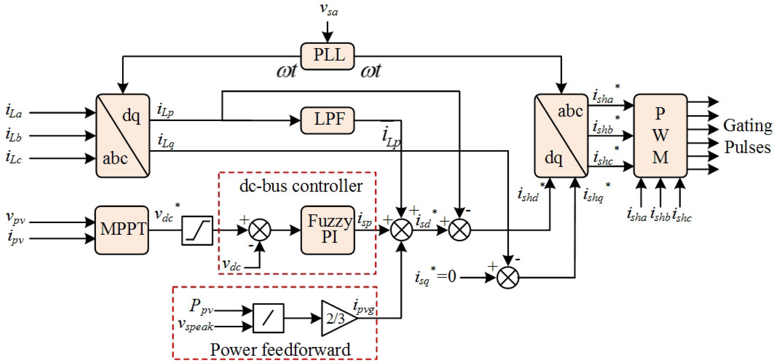
3.1. Control of the Compensators

The series compensator is used to stabilize the load voltage by injecting a certain amplitude of voltage with the same frequency and the same phase or the inverse phase when voltage sag/swell occurs. Thus, the series compensator is controlled to act as a voltage source. Simultaneously, the shunt compensator is responsible for compensating current harmonics and reactive power to reduce pollution for the grid. In the meantime, the shunt compensator takes charge of extracting active power from the photovoltaic cell. In this case, the shunt compensator was controlled as a current source. The structure diagram shown in Figure 2 and Figure 3 presents the series voltage control loop and shunt current control loop.
As seen in Figure 2, the reference load voltage in dq-axis v L d * and v L q * are supposed to be obtained to output the wanted compensating voltage. Assuming that there is no three-phase imbalance and the line is loss-free, after dq-axis transformation, the reference load voltage in dq-axis can be described as:
v L d * v L q * = 2 V s * 0
where V s * is the effective value of the grid voltage when no voltage fluctuation occurs. Additionally, as can be seen from Figure 3, in order to output the desired sinusoidal current, the reference grid current i s d * should be obtained as follows:
i s d * = i ¯ L p + i s p i p v g
where i ¯ L p is the dc component of the load active current, i s p represents the output current of the dc-bus controller, and i p v g is the output current of power feedforward. The quantity i ¯ L p could be obtained by phase-locked loop and coordinate transformation as follows:
i ¯ L p = 2 i L 1 cos ( θ u θ i )
The power feedforward unit could accelerate the power balance and improve the dynamic performance under sudden irradiation changes, the quantity i p v g could be estimated by:
i p v g = 2 v p v i p v 3 V s p
where v p v and i p v are the voltage and current of the photovoltaic array respectively and V s p denotes the grid peak voltage. The quantity i s p is the output current from the dc-bus controller, which maintains the stability of the dc-bus voltage, and the details are expounded in the following subsections.

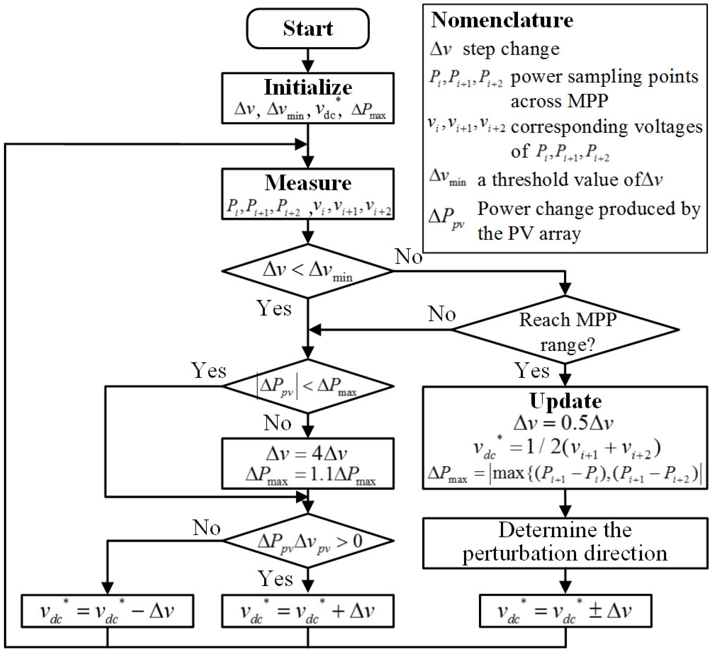
3.2. DC-Bus Voltage Reference

Generally, the dc-bus reference voltage v d c * is obtained from the maximum power point tracking (MPPT) technique based on perturb and observe (P&O). However, it is difficult for P&O to take into account both accuracy and tracking speed. This is because during the tracking process, smaller Δ v means slower tracking speed and greater energy loss, whereas larger Δ v brings a greater energy loss close to the maximum power point (MPP). Therefore, an improved MPPT based on P&O is proposed in this paper, aimed at generating the reference voltage quickly and reducing the energy loss at the same time.
A flowchart of proposed improved MPPT technique is shown in Figure 4. As can be seen from Figure 4, the step change Δ v is real-time adjusting according to the system state. That is to say, the step size is greater when it is far away from the MPP to reach the MPP range faster. The step size is controlled to be smaller to realize the MPPT precisely. Considering all the circumstances of acrossing MPP, it can be assumed to reach the MPP range to meet the conditions of P i + 1 P i 0 and  P i + 1 P i + 2 0 .

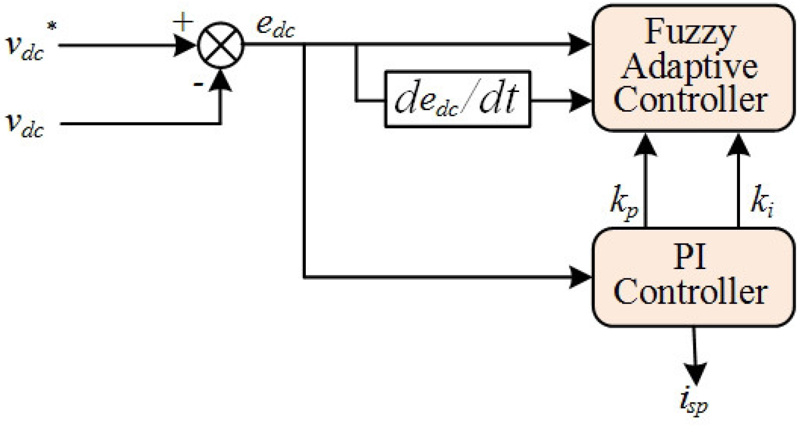
3.3. DC-Bus Controller Based on Fuzzy Adaptive-PI

The PI controller is conventionally adopted by the dc-bus controller to regulate the voltage of the dc-bus. However, the control performance depends heavily on the accurate determination of control parameters. For instance, greater integral parameter results in larger overshoot and severe oscillation in the dc-bus, while a smaller integral parameter makes slower voltage-follower speed. The latter influence is much more serious especially in the PV-UPQC system proposed in this paper. Due to the PV array being highly susceptible to solar radiation, the reference voltage of the dc-bus in the PV-UPQC system is strong time-varying, which is hard to meet for the system dynamic requirement. Similarly, the determination of proportion parameter is confronted with the same predicament. In such cases, the fuzzy adaptive-PI controller for the dc-bus voltage is proposed in this paper to improve voltage regulation performance, which is taking advantage of the fast dynamic response and the robustness of fuzzy control.
The control strategy of the fuzzy adaptive PI controller for dc-bus is shown in Figure 5. The proportion parameter k p and the integral parameter k i of the PI controller are adjusted adaptively by the fuzzy controller via tracking the voltage error e d c and its change rate d e d c / d t . When e d c is great, k p is supposed to select a higher value to correct the difference rapidly. Conversely, when e d c is small enough, k i is moderately increasing to eliminate steady state errors. If both e d c and d e d c / d t are not very large, then the situation of opposite sign means approaching steady state and the value of k p is supposed to be decreasing to a certain degree. However, the situation of the same sign shows deviation from the stability, then the value of k p should be added a little and the value of k i should be moderate. Hence, based on the above analysis, the fuzzy adaptive control matrices applied to the proposed dc-bus controller is shown in Table 1. In addition, the output current of the dc-bus controller i s p can be described as follows:
i s p = 2 3 v s p ( P L P p v + C d c Δ v d c 2 T s )
where v s p is the voltage peak, P L denotes the power consumed by loads, P p v represents the power produced by the PV array, Δ v d c is the dc-bus voltage variation after a power frequency period, and T s represents a power frequency period.

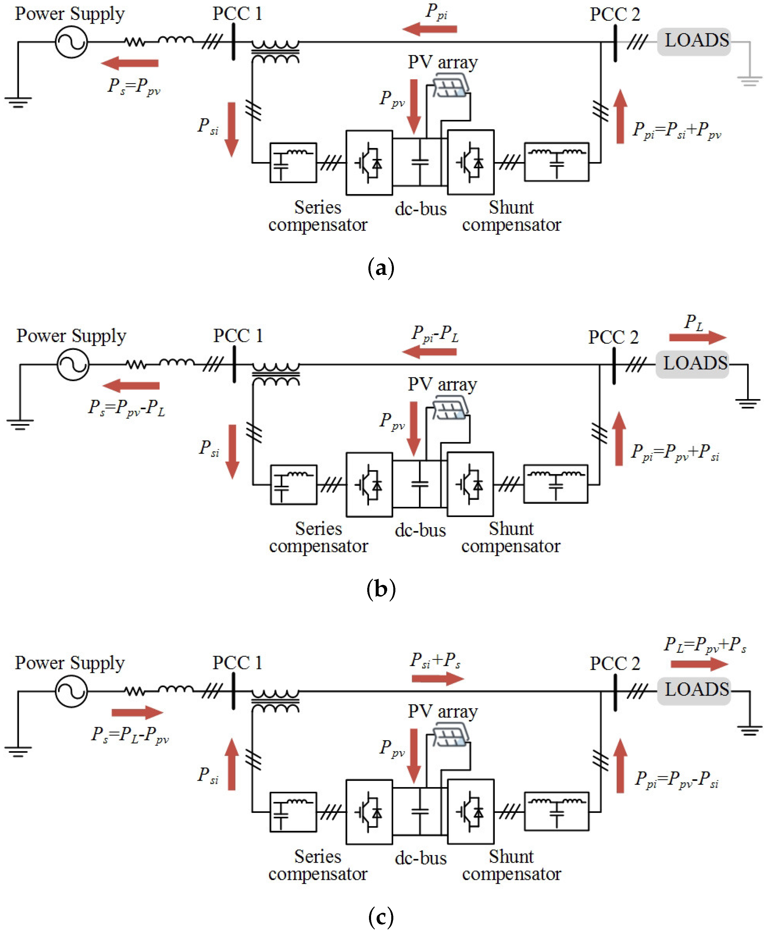
4. Coordination Control under Severe Voltage Sag

In this section, the functionality of the severe voltage sag compensation via coordination control is emphasized since the compensation ability is limited by the current flowing through the series compensator when voltage sag occurs.
Generally, the active power could be absorbing or generating via the shunt compensator to maintain the stability of the dc-bus and the output power of the PV array when voltage sag occurs. However, with the growing depth of voltage sag, the current flowing through the series compensator is increasing rapidly. In such a case, the voltage compensating capacity is confined due to the current limitation of series compensator. Therefore, the active current is bordered by the coordination control of the PV-UPQC system to enhance the compensation capacity for voltage sags.
The analysis of the active power flows through the proposed system under severe voltage sags as presented in Figure 6. In Figure 6a, as P L = 0 W, all energy produced by the PV array is delivered to the grid before voltage sags. When voltage sag occurs, the grid current I s a g is increasing. If I s a g is not up to the upper limit current of the series compensator I s i max , the PV array is still working at the maximum power point, and the power delivered to the grid is not changeable. However, if  I s a g I s i max , the power generated from the shunt compensator is limited and the power balance is broken. At this moment, the extra active power is stored in the dc-bus, which results in the rise of the dc-bus voltage and the decline of photovoltaic output power. That is to say, the power balance is achieved then in case of v d c < v d c max , the compensation capability is enhanced at the cost of taking some output power away from the PV array.
Figure 6b,c demonstrate the severe voltage sag situation when P L < P p v and P L > P p v respectively. In the case of P L < P p v , part of the energy produced from the PV array is delivered to the grid and the other part is delivered to the loads, while in case of P L > P p v , all energy produced from the PV array and the grid is delivered to the loads. As mentioned above, the grid current increases when voltage sag occurs. If I s a g < I s i max , the PV array still works at the maximum power point, otherwise, the output power of the shunt compensator is confined and the dc-bus voltage declines under its minimum value of maintaining normal operation to make the PV-UPQC system withdraw safely. The proposed coordination control strategy for improving the compensation capability of the voltage sags can be summarized in Algorithm 1.
Algorithm 1 The proposed coordination control strategy
1:
Sampling voltage values and detecting sag magnitude
2:
if Voltage sag occurs then
3:
    if v d c > v d c max then
4:
        The PV array stops working
5:
    else
6:
        if v d c < v d c min then
7:
           The PV-UPQC system stops working
8:
        else
9:
           Conventional MPPT algorithm
10:
           Limiting the reference active current
11:
        end if
12:
    end if
13:
end if
14:
final
15:
return v o l t a g e v a l u e s and s a g m a g n i t u d e

5. Results and Discussions

The analysis of the proposed integrated photovoltaic-UPQC system was done in Matlab/Simulink and PLECS environment. PLECS is able to conduct simulations for a power electronics system, while Matlab is flexible in constructing a control circuit. The AC three-phase voltage source was of 380 V at 50 Hz, feeding the nonlinear R-L-C load. The voltage class of the solar panel was 750 V and the temperature was set to 25 C. Other experiment parameters of grid-side and load-side filters are represented in Section 2. For a better illustration on the proposed integrated photovoltaic-UPQC system, the simulation and validation section was divided into four cases. Case 1 discusses the validity and applicability of the proposed system, under voltage sag or voltage swell when P L = 0 , 0 < P L < P p v , and P L > P p v . Case 2 analyzes the system performance when external conditions change dramatically, for instance, load capacity and solar irradiance. Some comparison simulation experiments are conducted in Case 3, which demonstrates the superiority of the fuzzy adaptive PI controller and the power feedforward unit. Lastly, the simulation results under severe voltage sag are presented in Case 4.

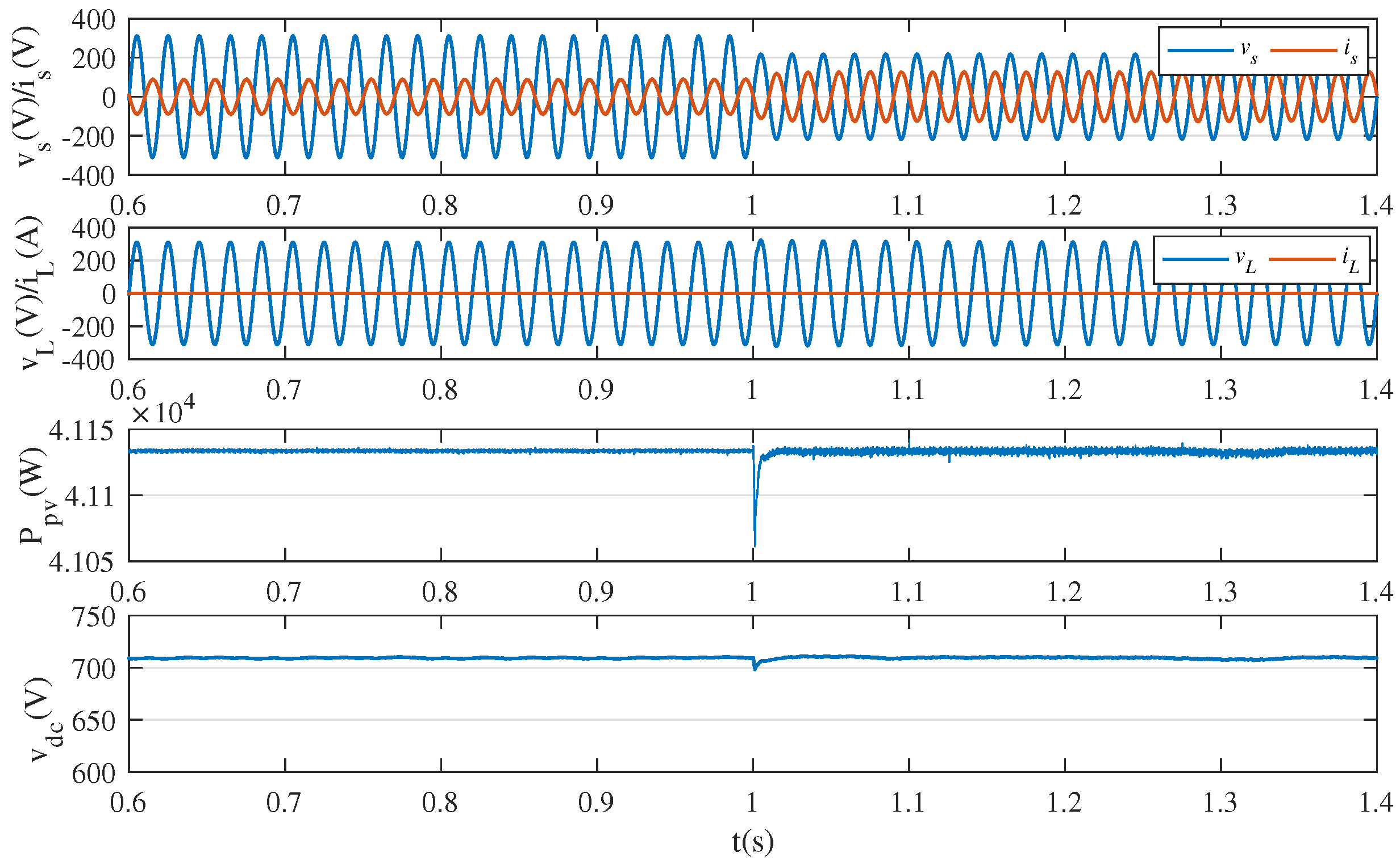
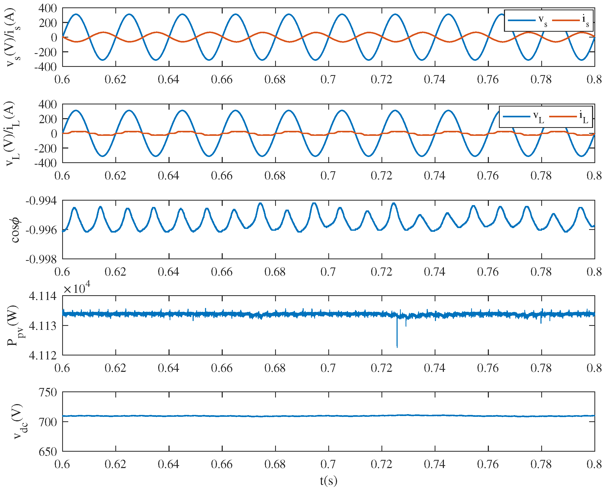
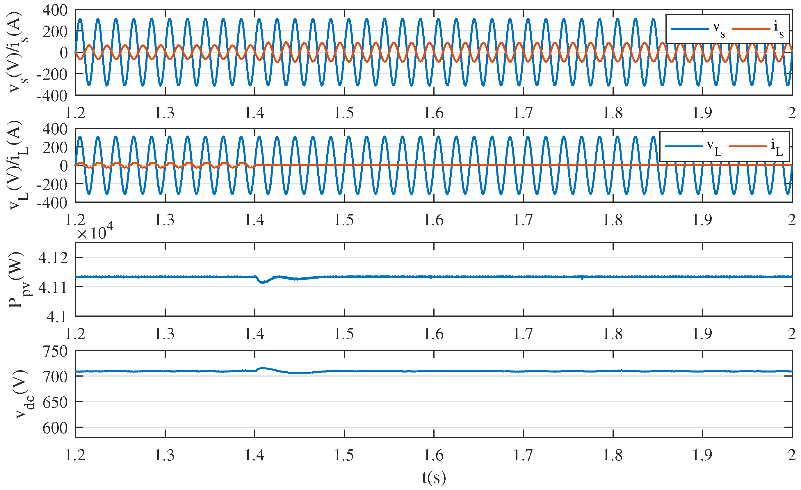
5.1. Case 1: Simulation Results of the Overall System

The dynamic performance of the PV-UPQC system under voltage sags without load connection is shown in Figure 7, as a matter of convenience, only phase-A is selected for analyzing. The voltage sag occurred at 1 s with a sag magnitude of 0.3 p.u. The irradiation was S = 1000 W/m 2 . The nominal power was 41.35 kW and the instantaneous power was 41.13kW. The various parameters in the simulation results were grid voltages ( v s ), grid currents ( i s ), load voltages ( v L ), load currents ( i L ), photovoltaic output power ( P p v ), and dc-bus voltage ( v d c ). It was observed that the load side voltage remained stable after grid voltage sag because the voltage was compensated by the series compensator. Under the circumstances, the loads could be connected at any time and the normal operation of the loads could be guaranteed. In order to ensure power balance, the grid current increased. Meanwhile, the dc-bus voltage restored stability after experiencing small vibrations for a short time. Correspondingly, there were some small fluctuations on the output power of the PV array.
The performance of the proposed system of harmonic and reactive power compensation with full loads access is shown in Figure 8 and Figure 9. The irradiation of S = 1000 W/m 2 and phase-A was chosen for analysis. The grid-side power factor ( cos ϕ ) is also shown in Figure 8. The total harmonic distortion (THD) load current and grid current through the Fourier transform are shown in Figure 9. It should be noted that the system reached the power balance and the dc-bus voltage maintained stability. However, the photovoltaic cell output power divided into two parts, some power flowed to the grid, while the other power flowed to the loads. The grid current maintained stability, which is close to the standard sine wave. It can be observed that the harmonic content of the current declined obviously, which accomplished the mitigation of harmonic compensation for loads. Meanwhile, the grid current and the grid voltage were in reverse phase, the power factor remained between −0.994 and −0.997, thus the reactive power compensation for the loads were conducted.
Besides, the dynamic performance of the PV-UPQC system under conditions of voltage swells is shown in Figure 10. The irradiation was set as S = 200 W/m 2 with full loads access, which means P L > P p v . Beginning with t = 2 s, there was a voltage swell of 0.3 p.u. The series compensator compensated for the load voltage by injecting a suitable voltage in the opposite phase to maintain the load at rated voltage condition and normal work.

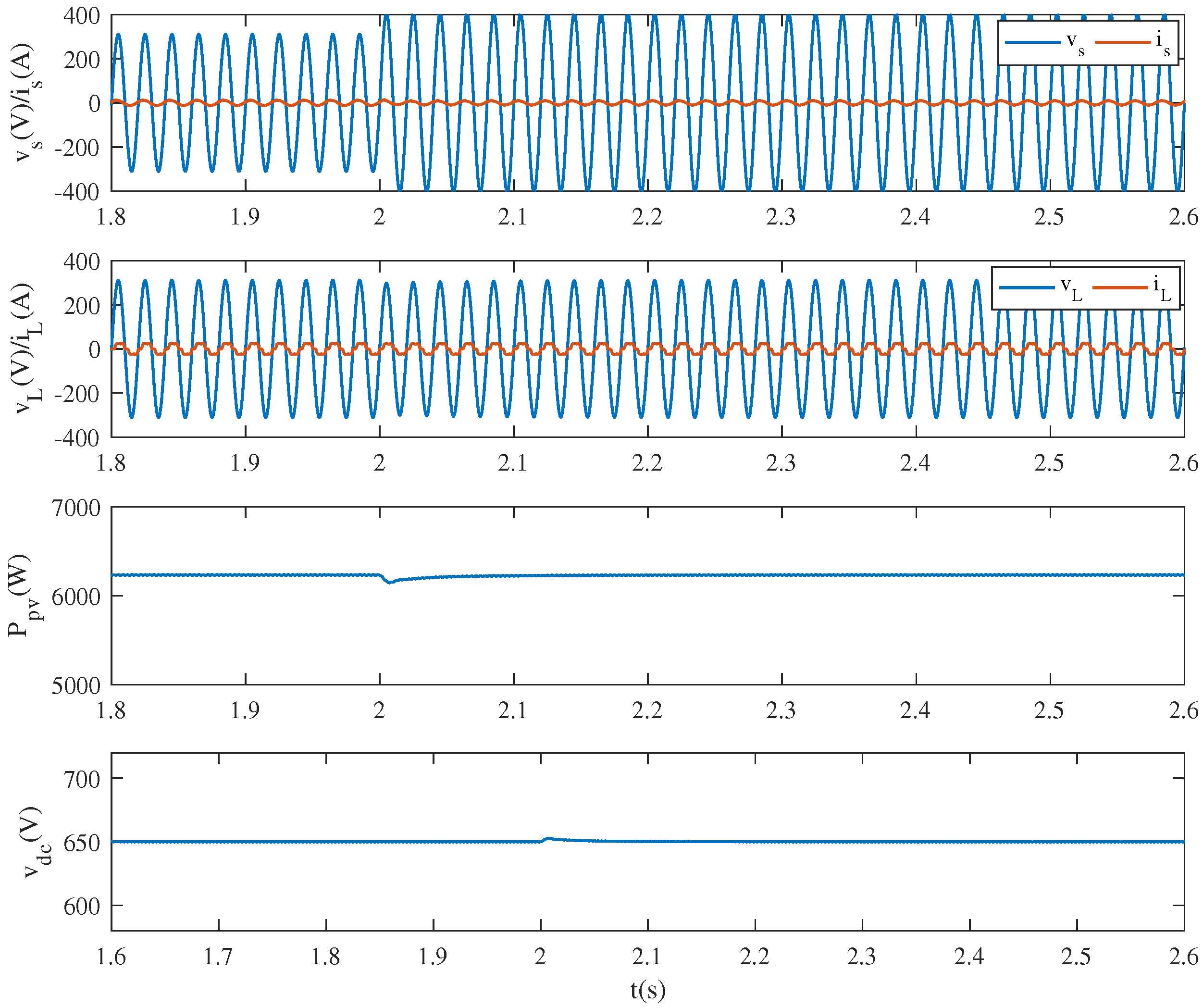
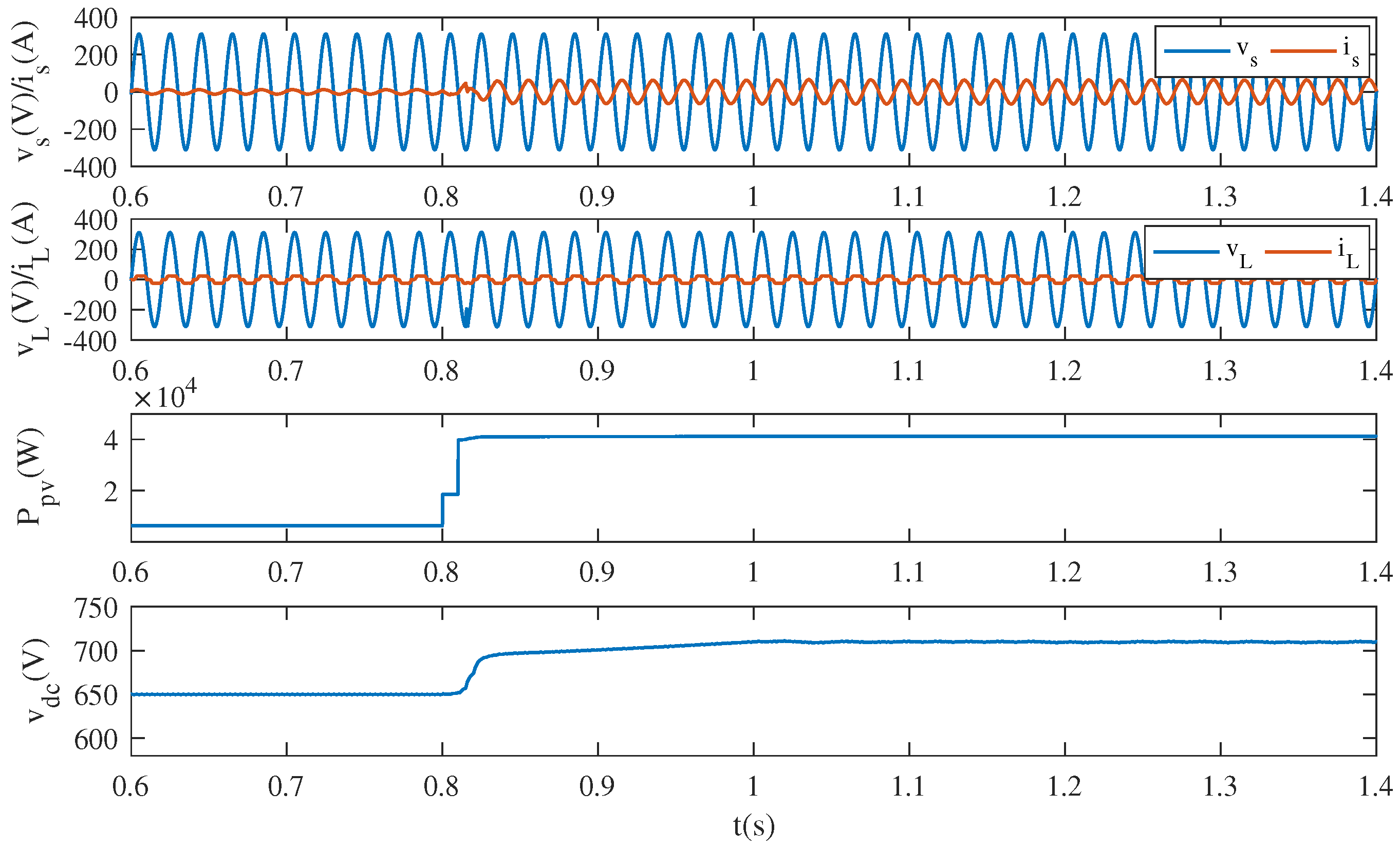
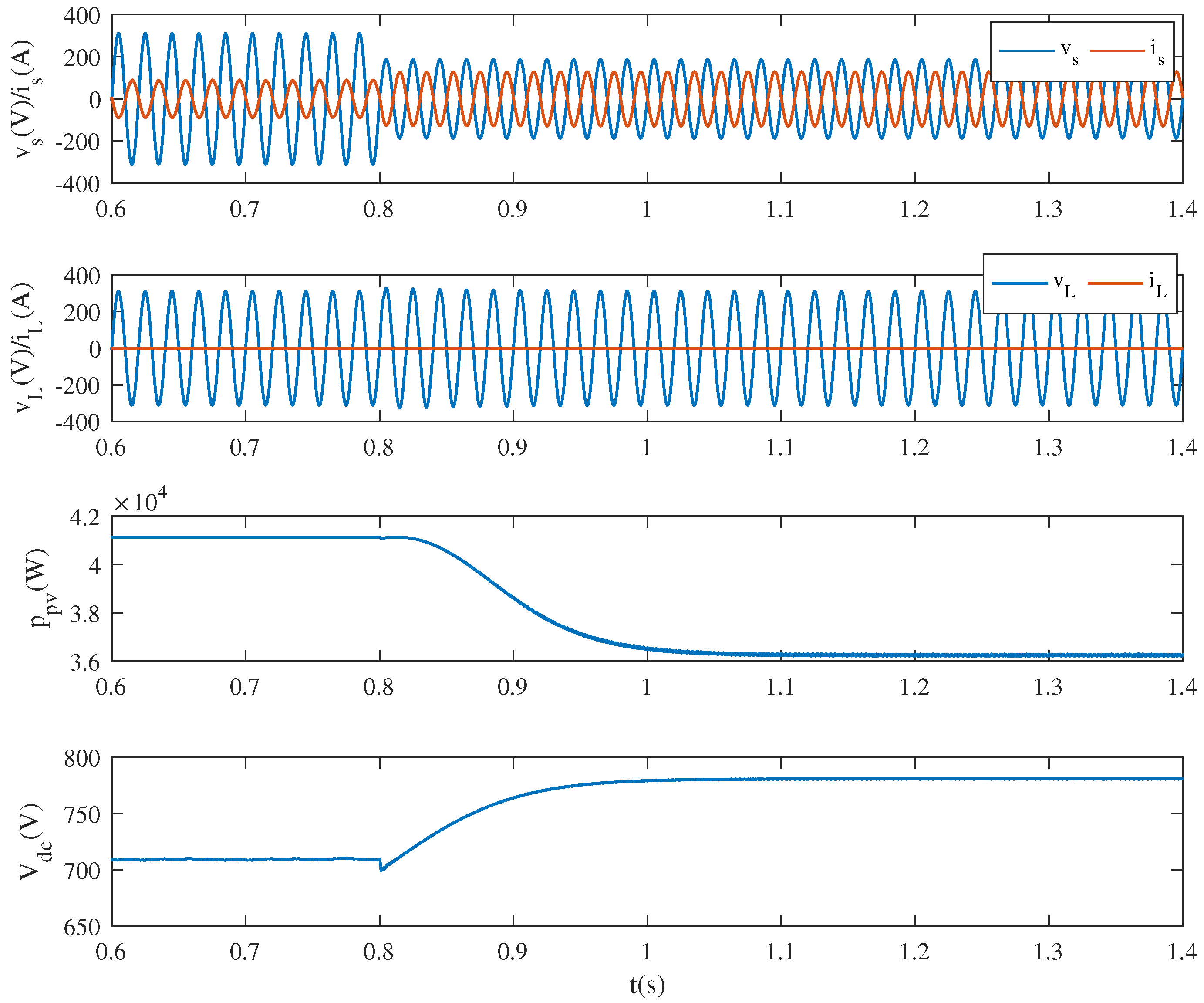
5.2. Case 2: Simulation Results under Conditions of External Changes

Figure 11 presents the dynamic behavior of the integrated PV-UPQC system considering the loads sudden change. At t = 1.4 s, the load’s rate dropped suddenly from 100% to 0%. As noted, the grid current increased so that the grid power would increase as well. The load voltage was still stable to get ready for reconnecting loads. The dc-bus voltage regained stabilization after 0.1 s, while the photovoltaic output power restored stability at t = 1.5 s. Figure 12 shows the dynamic performance of the proposed system considering the irradiation sudden change with full loads access. As noted, the illumination intensity increased suddenly from S = 200 W/m 2 to S = 1000 W/m 2 at t = 0.8 s. Due to the increase of the photovoltaic output power, the grid current became in phase with the grid voltage instead of reversed phase. Therefore, the grid changed from output power into absorbing power, while the load voltage maintained stability to ensure the normal operation of the loads. The dc-bus voltage made a difference due to the irradiation change from 650 V to 710 V through for 0.2 s and the photovoltaic output power restored stability at t = 1 s.

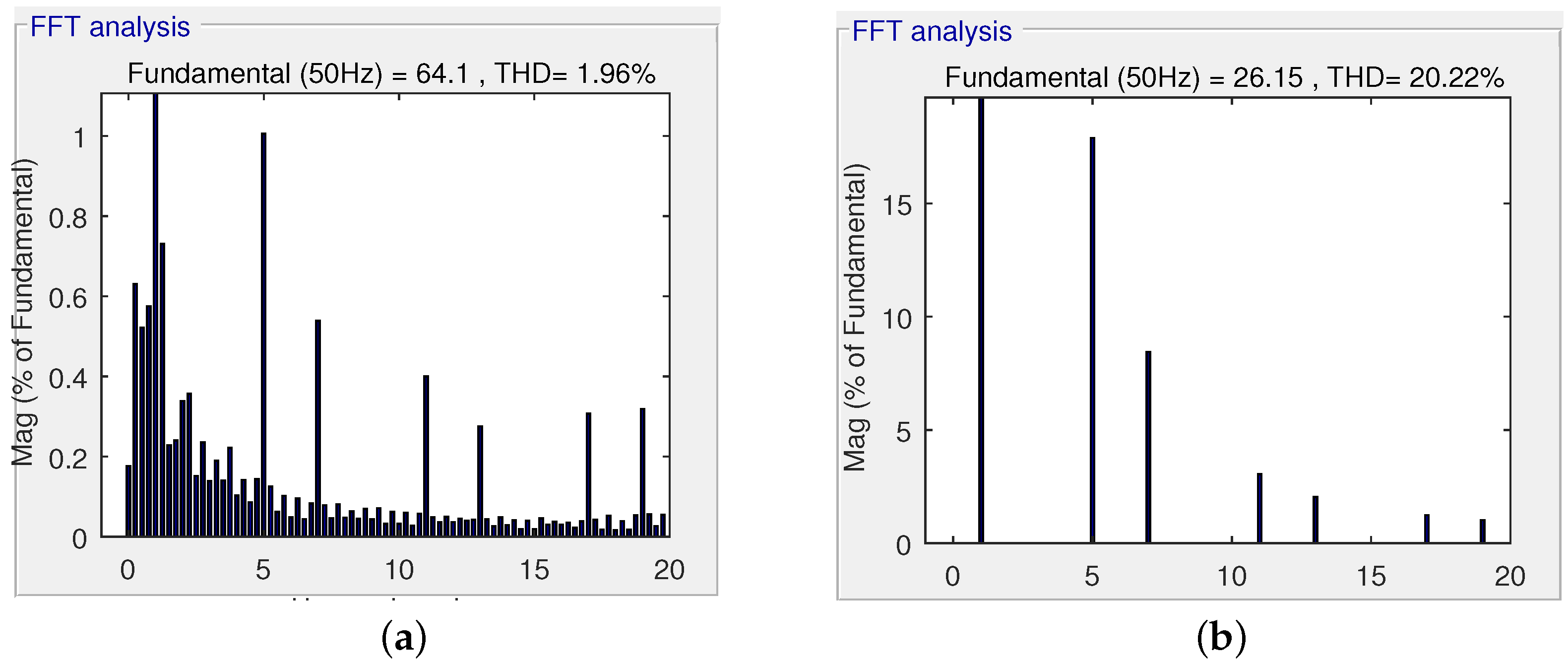
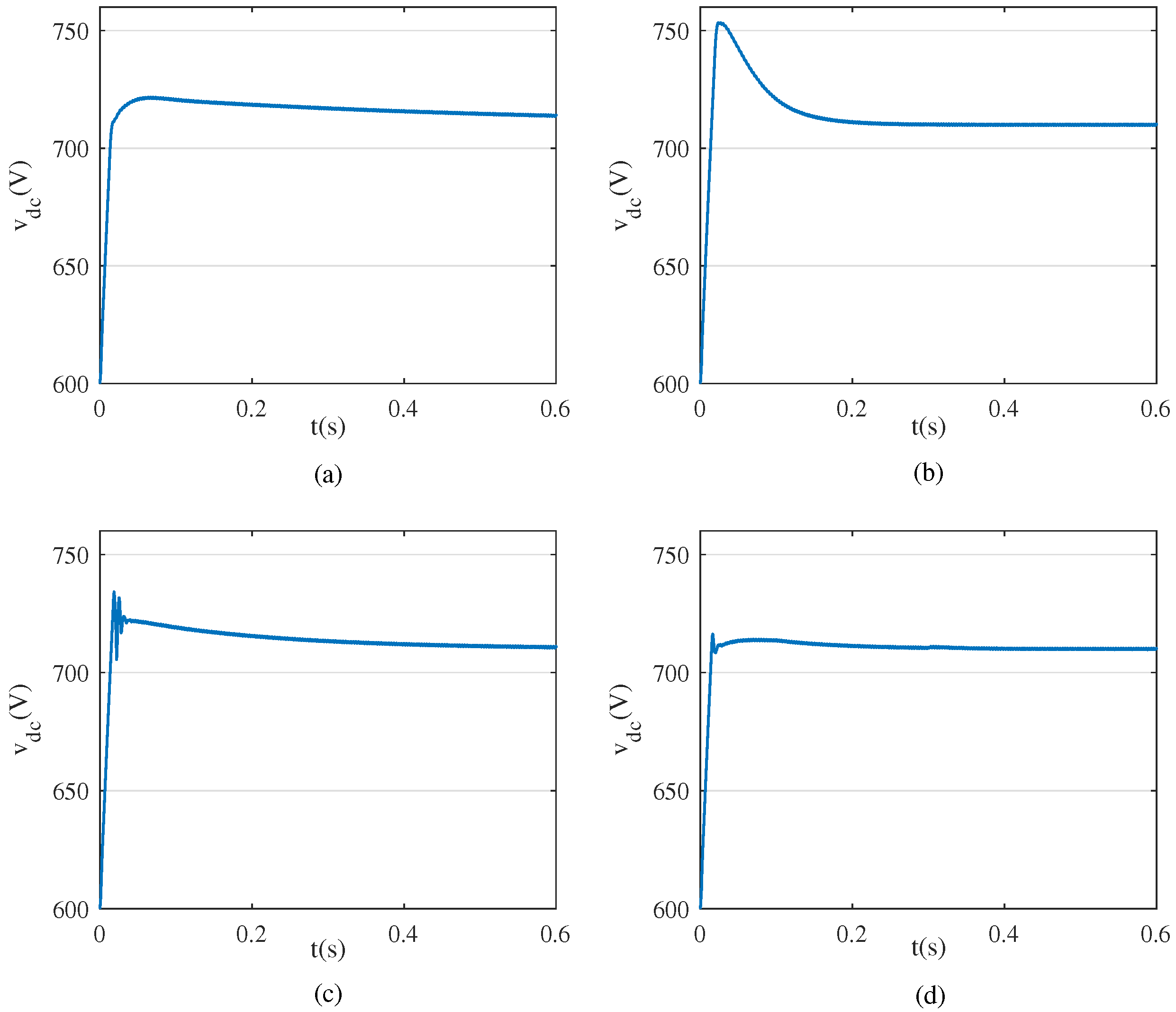
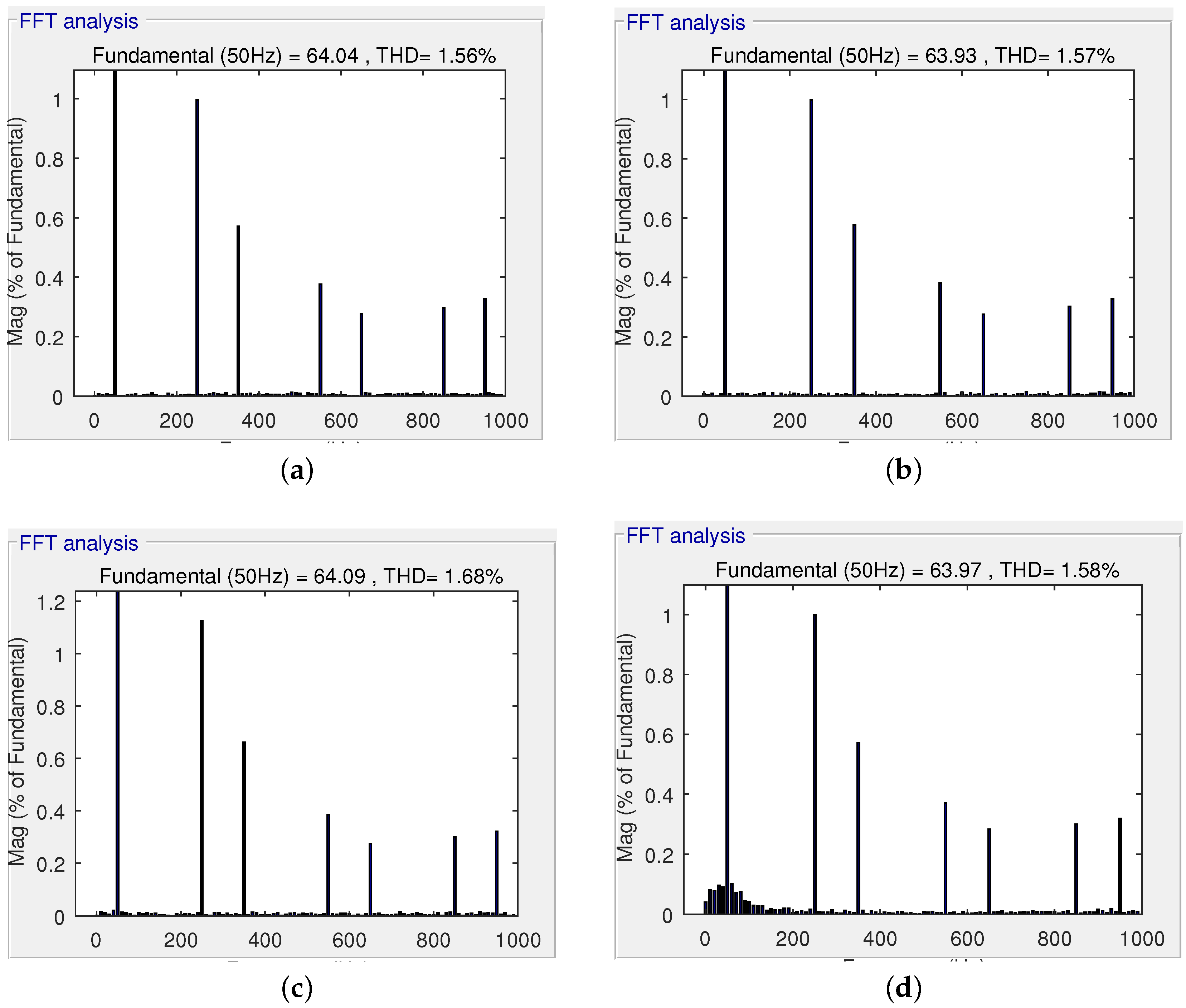
5.3. Case 3: Comparison Simulation Results

Figure 13 demonstrates the advantageous performance of the feedforward unit. In Figure 13, the irradiation decreased suddenly from S = 1000 W/m 2 to S = 200 W/m 2 at t = 1.4 s with full loads connection. It should be noted that compared to the integrated system without the feedforward unit, the dc-bus voltage oscillation amplitude of the proposed system with feedforward unit reduced significantly and the recovery stability time of the dc-bus voltage decreased as well.
Figure 14 and Figure 15 present the superiority of the proposed fuzzy adaptive PI controller. For the sake of analysis, a reference value of the dc-bus voltage was set as v d c * = 710 V . As noted, the following speed of the dc-bus voltage increased along with the increase of the value of k i , which brought about the relatively large overshoot at the same time. It can also be concluded that the value of k i had little influence on harmonics compensation performance. Additionally, the overshoot reduced along with the increase of the value of k p , though the harmonics compensation performance are affected. However, the proposed system based on the fuzzy adaptive PI controller could guarantee the harmonics compensation performance as well as increase the following speed and reduce the overshoot.

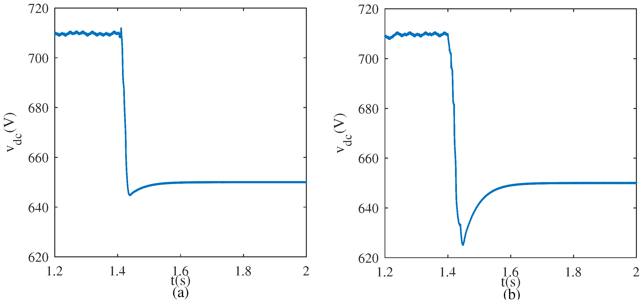
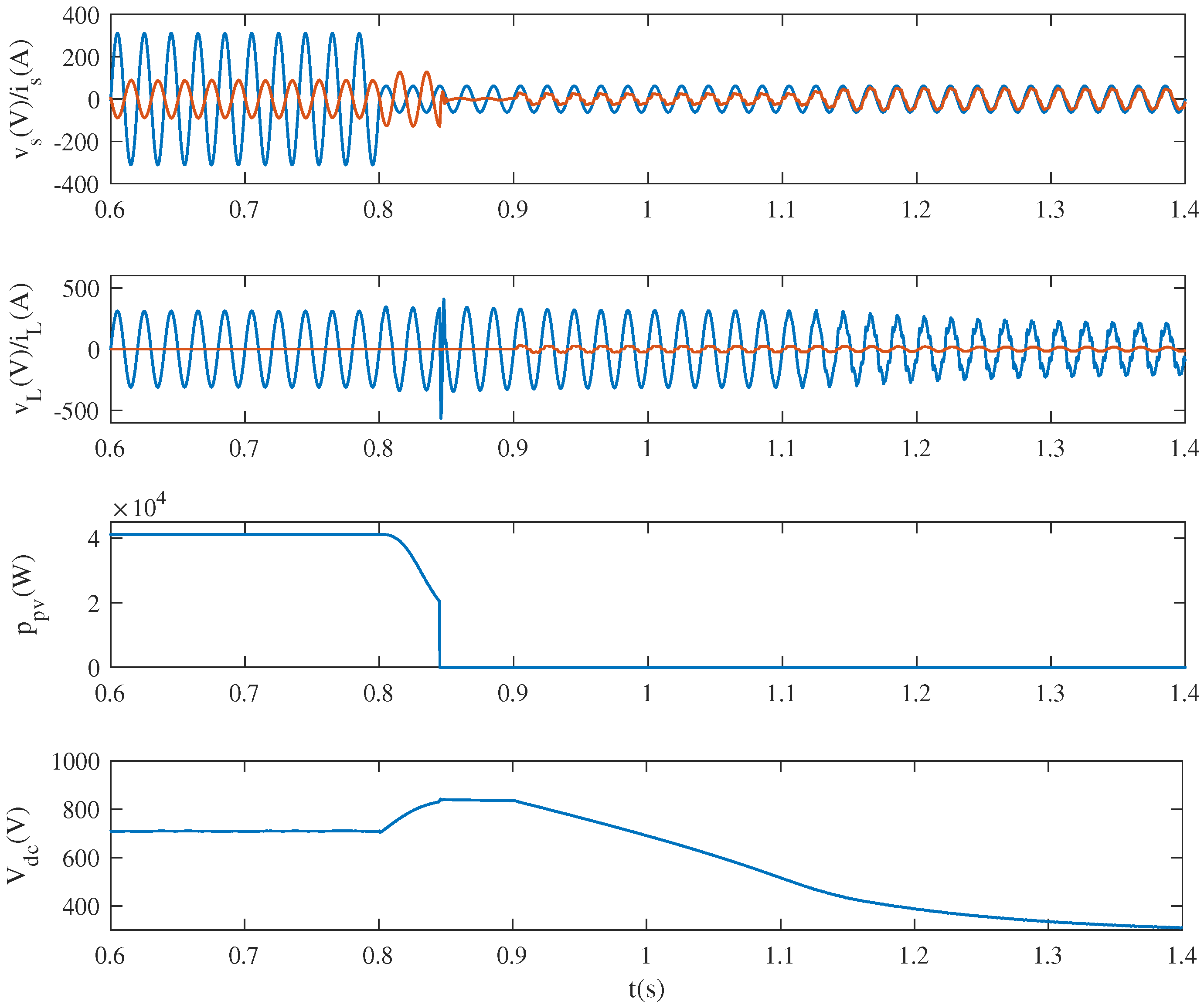
5.4. Case 4: Simulation Results under Severe Voltage Sag

Suppose that the output power of photovoltaic cell reached its maximum when S = 1000 W/m 2 and according to the power balance relation, the limiting current was selected as I lim = 130 A . Figure 16 presents the dynamic performance of the PV-UPQC system under severe voltage sags without load connection. The voltage sag occurred at 0.8 s with a sag magnitude of 0.4 p.u. In these circumstances, there will be an overcurrent from the series compensator by utilizing the regular control strategy. However, the peak value of grid current i s max = 129 A by adopting the proposed coordinate control strategy without the overcurrent and the load voltage maintained stability, which means that the system compensation capacity increased. Due to the limited power of the shunt compensator, the dc-bus voltage increased and the photovoltaic power reduced to reach a new balance. It can be concluded that some photovoltaic power was sacrificed to enhance the voltage sag compensation ability of the system.
Figure 17 demonstrates the dynamic performance of the proposed system under severe voltage sags with a magnitude of 0.8 p.u. at t = 0.8 s . As can be seen, the active current of shunt compensator was limited by adopting the proposed coordinate control strategy, which resulted in the increase of the dc-bus voltage and the decrease of photovoltaic output power. However, the voltage sag was much deeper in this context, thus the rising speed of dc-bus voltage was faster.
The dc-bus voltage reached its upperlimit, v d c max = 830 V in this simulation environment at t = 0.84 s. At this moment, the photovoltaic cell stopped working so that the output power turned to zero and the dc-bus voltage declined gradually. The loads connected at t = 0.9 s, the dc-bus acted as a buffer to protect the loads, and the dc-bus voltage started to decline rapidly afterwards. The dc-bus voltage reached its lower limit value at t = 0.84 s, since then the voltage compensation performance was discounted heavily, thus there was no occasion to offer protection for loads against voltage sags. In this context, the system would be out of service if the grid voltage was not restored.

6. Conclusions

This paper investigated an integrated photovoltaic-UPQC system and its control strategy aimed at the problems of the existing PV-UPQC system, which are the understable dc-bus voltage and the lack of mitigation ability under severe voltage sags. In this manuscript, the dc-bus voltage stability was enhanced based on the proposed fuzzy adaptive PI controller tied up with the improved MPPT technique. The compensation performance of severe voltage sag increased based on the proposed coordinate control strategy. A complete set of simulation results were presented to validate the effectiveness of the proposal done with the integration of MATLAB and PLECS. By observing the simulation waveforms, the dynamic performance of the grid voltages/currents, load voltages/currents, PV output power, and dc-bus voltage before and after compensation showed the impact of the proposed PV-UPQC system over the power quality issues. The results clearly demonstrated that the proposed PV-UPQC system was capable of mitigating voltage sags, voltage swells, load harmonic, and reactive power, which could solve the power quality problems when power quality phenomenon occurs, and generate photovoltaic power under a stable operation of power grid.

Author Contributions

Conceptualization, D.Y. and Z.M. (Zhanchao Ma); Methodology, Z.M. (Zhuang Ma); Software, Z.M. (Zhanchao Ma) and Z.M. (Zhuang Ma); Writing—original draft, X.G. and E.C.; Writing—review & editing, D.Y. and X.G.

Funding

This research was funded by the National Natural Science Foundation of China grant number 61433004.

Acknowledgments

We would like to thank the Managing Editor and anonymous reviewers for their help to improve the manuscript.

Conflicts of Interest

The authors declare no conflict of interest.

Abbreviations

The following abbreviations are used in this manuscript:
PVPhotovoltaic
UPQCUnified Power Quality Conditioner
PQPower Quality
APFActive Power Filter
SVCStatic Var Compensator
SVGStatic Var Generator
STATCOMStatic Synchronous Compensator
DVRDynamic Voltage Restorer
UPSUninterruptible Power Supply
MPPTMaximum Power Point Tracking
L r a , L r b , L r c LC-filter inductances
C r a , C r b , C r c LC-filter capacitances
L f a , L f b , L f c LCL-filter inductances
C f a , C f b , C f c LCL-filter capacitances
v L r , v C r Voltages of inductors L r and capacitors C r
i L r , i C r Currents of inductors L r and capacitors C r
v s Grid voltages
i s Grid currents
nTransformation ratio
v L f 1 , v L f 2 , v C f Voltages across L f 1 , L f 2 , and C f
i s h , i c h , i C f Currents of L f 1 , L f 2 , and C f
v L Load voltages
i L Load currents
v p i Output voltages of the inverter
mModulation depth
aOverload capacity
f s i Switching frequency
i r Inductor current ripple
v L d * , v L q * Reference load voltage in dq-axis
V s * Effective value of grid voltage
i s d * Reference grid current
i s p Output current of dc-bus controller
i p v g Output current of power feedforward
v d c Voltage of dc-bus
P p v Photovoltaic output power

References

  1. Heydt, G.; Ayyanar, R.; Hedman, K.W.; Vittal, V. Electric power and energy engineering: The first century. Proc. IEEE 2012, 100, 1315–1328. [Google Scholar] [CrossRef]
  2. Montoya, F.; Banos, R.; Alcayde, A.; Montoya, M.; Manzano-Agugliaro, F. Power quality: Scientific collaboration networks and research trends. Energies 2018, 11, 2067. [Google Scholar] [CrossRef]
  3. Zissis, G. Power quality: Society’s underpinning. IEEE Ind. Appl. Mag. 2019, 25, 5–6. [Google Scholar]
  4. Dugan, R.; McGranaghan, M.; Santoso, S.; Beaty, H. Electrical Power Systems Quality, 3rd ed.; McGraw-Hill Companies: Singapore, 2012. [Google Scholar]
  5. Choi, W.; Lee, W.; Han, D.; Sarlioglu, B. New configuration of multifunctional grid-connected inverter to improve both current-based and voltage-based power quality. IEEE Trans. Ind. Appl. 2018, 54, 6374–6382. [Google Scholar] [CrossRef]
  6. Pradhan, M.; Mishra, M. Dual p-q theory based energy-optimized dynamic voltage restorer for power quality improvement in a distribution system. IEEE Trans. Ind. Electron. 2019, 66, 2946–2955. [Google Scholar] [CrossRef]
  7. Hamad, M.; Masoud, M.; Wiiliams, B. Medium-voltage 12-pulse converter: Output voltage harmonic compensation using a seiries APF. IEEE Trans. Ind. Electron. 2014, 61, 43–52. [Google Scholar] [CrossRef]
  8. Wan, Y.; Murad, M.A.A.; Liu, M.; Milano, F. Voltage frequency control using SVC devices coupled with voltage dependent loads. IEEE Trans. Power Syst. 2019, 34, 1589–1597. [Google Scholar] [CrossRef]
  9. Luo, R.; He, Y.; Liu, J. Research on the unbalanced compensation of delta-connected cascaded H-bridge multilevel SVG. IEEE Trans. Ind. Electron. 2018, 65, 8667–8676. [Google Scholar] [CrossRef]
  10. Hock, R.; Novaes, Y.; Batschauer, A. A voltage regulator for power quality improvement in low-voltage distribution grids. IEEE Trans. Power Electron. 2018, 33, 2050–2060. [Google Scholar] [CrossRef]
  11. Somayajula, D.; Crow, M. An integrated dynamic voltage restorer-ultracapacitor design for improving power quality of the distribution grid. IEEE Trans. Sustain. Energy 2015, 6, 616–624. [Google Scholar] [CrossRef]
  12. Admir, M.; Mekhilef, S. An online transformerless uninterruptible power supply (UPS) system with a smaller battery bank for low-power applications. IEEE Trans. Power Electron. 2017, 32, 233–247. [Google Scholar]
  13. Khadkikar, V.; Chandra, A. UPQC-S: A novel concept of simultaneous voltage sag/swell and load reactive power compensations utilizing series inverter of UPQC. IEEE Trans. Power Electron. 2011, 26, 2414–2425. [Google Scholar] [CrossRef]
  14. Rahimi, K.; Mohajeryami, S.; Majzoobi, A. Effects of photovoltaic systems on power quality. In Proceedings of the 2016 North American Power Symposium, Denver, CO, USA, 18–20 September 2016; pp. 1–6. [Google Scholar]
  15. Kow, K.; Wong, Y.; Rajkumar, R.; Rajkumar, R.K. A review on performance of artificial intelligence and conventional method in mitigating PV grid-tied related power quality events. Renew. Sust. Energ. Rev. 2016, 56, 334–346. [Google Scholar] [CrossRef]
  16. Dasgupta, S.; Sahoo, S.; Panda, S.; Amaratunga, G. Single-phase inverter-control techniques for interfacing renewable energy sources with microgrid-part I: parallel-connected inverter topology with active and reactive power flow control along with grid current shaping. IEEE Trans. Power Electron. 2011, 26, 717–731. [Google Scholar] [CrossRef]
  17. Amjad, A.; Salam, Z. A review of soft computing methods for harmonics elimination PWM for inverters in renewable energy conversion systems. Renew. Sustain. Energ. Rev. 2014, 33, 141–153. [Google Scholar] [CrossRef]
  18. Romero-Cadaval, E.; Spagnuolo, G.; Franquelo, L.; Ramos-Paja, C.A.; Suntio, T.; Xiao, W.M. Grid-connected photovoltaic generation plants: Components and operation. IEEE Ind. Electron. Mag. 2013, 7, 6–20. [Google Scholar] [CrossRef]
  19. Rajakumar, P.; Saravanakumar, R.; Thirumalaivasan, R. Power quality enhancement using photovoltaic based dynamic voltage restorer. In Proceedings of the 2014 International Conference on Advances in Electrical Engineering (ICAEE), Vellore, India, 9–11 January 2014; pp. 1–4. [Google Scholar]
  20. Rauf, A.; Khadkikar, V. Integrated photovoltaic and dynamic voltage restorer system configuration. IEEE Trans. Sustain. Energy 2015, 6, 400–410. [Google Scholar] [CrossRef]
  21. Babaei, E.; Shahir, F.; Tabrizi, S.; Sabahi, M. Compensation of voltage sags and swells using photovoltaic source based DVR. In Proceedings of the 14th International Conf. Electrical Engineering (ECTI), Phuket, Thailand, 27–30 June 2017; pp. 903–906. [Google Scholar]
  22. Khadkikar, V. Enhancing electric power quality using UPQC: A comprehensive overview. IEEE Trans. Power Electron. 2012, 27, 2284–2296. [Google Scholar] [CrossRef]
  23. Karanki, S.; Geddada, N.; Mishra, M.; Kumar, B. A modified three-phase four-wire UPQC topology with reduced DC-link voltage rating. IEEE Trans. Ind. Electron. 2013, 60, 3555–3566. [Google Scholar] [CrossRef]
  24. Ye, J.; Gooi, H.; Wu, F. Optimal design and control implementation of UPQC based on variable phase angle control method. IEEE Trans. Ind. Inform. 2018, 14, 3109–3123. [Google Scholar] [CrossRef]
  25. Simatupang, D.; Choi, J. Integrated photovoltaic inverters based on unified power quality conditioner with voltage compensation for submarine distribution system. Energies 2018, 11, 2927. [Google Scholar] [CrossRef]
  26. Palanisamy, K.; Kothari, D.; Mishara, M.; Meikandashivam, S.; Raglend, I.J. Effective utilization of unified power quality conditioner for interconnecting PV modules with grid using power angle control method. Int. J. Electr. Power Energy Syst. 2013, 48, 131–138. [Google Scholar] [CrossRef]
  27. Devassy, S.; Singh, B. Modified pq-theory-based control of solar-PV-integrated UPQC-S. IEEE Trans. Ind. Appl. 2017, 53, 5031–5040. [Google Scholar] [CrossRef]
  28. Devassy, S.; Singh, B. Control of solar photovoltaic integrated UPQC operating in polluted utility conditions. IET Power Electron. 2017, 10, 1413–1421. [Google Scholar] [CrossRef]
  29. Devassy, S.; Singh, B. Design and performance analysis of three-phase solar PV integrated UPQC. IEEE Trans. Ind. Appl. 2018, 54, 73–80. [Google Scholar] [CrossRef]
  30. Abhishek, K.; Rashmi, J. Implementation and Performance Evaluation of Three Phase Solar PV-UPQC for Power Quality Enhancement. Int. J. Eng. Manag. Res. 2017, 7, 744–751. [Google Scholar]
  31. Dash, S.; Ray, P. Investigation on the performance of PV-UPQC under distorted current and voltage conditions. In Proceedings of the 5th International Conference on Renewable Energy: Generation and Applications, Al Ain, UAE, 25–28 February 2018. [Google Scholar]
  32. Ambati, B.; Khadkikar, V. Optimal sizing of UPQC considering VA loading and maximum utilization of power-electronic converters. IEEE Trans. Power Deliv. 2014, 29, 1490–1498. [Google Scholar] [CrossRef]
  33. Senthilnathan, K.; Annapoorani, I. Implementation of unified power quality conditioner based on current source converters for distribution grid and performance monitoring through LabVIEW simulation interface toolkit server: A cyber physical model. IET Gener. Transm. Distrib. 2016, 10, 2622–2630. [Google Scholar] [CrossRef]
  34. Lakshmi, S.; Ganguly, S. Modelling and allocation of open-UPQC-integrated PV generation system to improve the energy efficiency and power quality of radial distribution networks. IET Renew. Power Gener. 2018, 12, 605–613. [Google Scholar] [CrossRef]
  35. Campanhol, L.; Silva, S.; Oliveira, A., Jr.; Bacon, V. Single-stage three-phase grid-tied PV system with universal filtering capability applied to DG systems and AC microgrids. IEEE Trans. Power Electron. 2017, 32, 9131–9141. [Google Scholar] [CrossRef]
  36. Reisi, A.; Moradi, M.; Showkati, H. Combined photovoltaic and unified power quality controller to improve power quality. Sol. Energy 2013, 88, 154–162. [Google Scholar] [CrossRef]
  37. Dash, S.; Ray, P. Novel PV-tied UPQC topology based on a new model reference control scheme and integral plus sliding mode dc-link controller. Int. Trans. Electr. Energy Syst. 2018, 28, 1–26. [Google Scholar] [CrossRef]
Figure 1. The complete configuration of the proposed photovoltaic system integrated unified power quality conditioner.
Energies 12 04009 g001
Figure 2. Control loop of the series compensator.
Energies 12 04009 g002
Figure 3. Control loop of the shunt compensator.
Energies 12 04009 g003
Figure 4. Flowchart of the improved MPPT (maximum power point tracking) technique.
Energies 12 04009 g004
Figure 5. Control loop of the fuzzy adaptive-PI controller for the dc-bus.
Energies 12 04009 g005
Figure 6. Active power flow through the proposed system under voltage sags. (a) V s < V L with P L = 0 , (b) V s < V L with P L < P p v , and (c) V s < V L with P L > P p v .
Energies 12 04009 g006
Figure 7. Simulation results under voltage sag with P L = 0 .
Energies 12 04009 g007
Figure 8. Simulation results of harmonic and reactive power compensation with 0 < P L < P p v .
Energies 12 04009 g008
Figure 9. Total harmonic distortion (THD) analysis of grid and load current under conditions with 0 < P L < P p v . (a) THD analysis of grid current and (b) THD analysis of load current.
Energies 12 04009 g009
Figure 10. Simulation results under voltage swell with P L > P p v .
Energies 12 04009 g010
Figure 11. Simulation results under loads sudden decrease.
Energies 12 04009 g011
Figure 12. Simulation results under irradiation sudden increase.
Energies 12 04009 g012
Figure 13. Comparison results of feedforward unit under condition of irradiation sudden decrease. (a) With a feedforward unit and (b) without a feedforward unit.
Energies 12 04009 g013
Figure 14. Comparison results between conventional PI controller and fuzzy adaptive PI controller. (a) Conventional PI controller with k p = 2 . 5 , k i = 5 , (b) conventional PI controller with k p = 2 . 5 , k i = 50 , (c) conventional PI controller with k p = 10 , k i = 50 , and (d) fuzzy adaptive PI controller.
Energies 12 04009 g014
Figure 15. THD comparison between conventional PI controller and fuzzy adaptive PI controller. (a) Conventional PI controller with k p = 2 . 5 , k i = 5 , (b) conventional PI controller with k p = 2 . 5 , k i = 50 , (c) conventional PI controller with k p = 10 , k i = 50 , and (d) fuzzy adaptive PI controller.
Energies 12 04009 g015
Figure 16. Simulation results under voltage sag of 0.4 p.u.
Energies 12 04009 g016
Figure 17. Simulation results under voltage sag of 0.8 p.u.
Energies 12 04009 g017
Table 1. Proposed fuzzy adaptive proportional and integral control matrices ( k p / k i , +: Positive Change, – Negative Change, 3: Big, 2: Medium, 1: Small, 0: Zero).
e dc −3−2−10+1+2+3
de dc / dt
−3−3/+3−3/+3−2/+2−2/+2−1/+10/00/0
−2−3/+3−3/+3−2/+2−1/+1−1/+10/0+1/+1
−1−2/+3−2/+2−2/+1−1/+10/0+1/−1+1/−1
0−2/+2−2/+2−1/+10/0+1/−1+2/−2+2/−2
+1−1/+2−1/+10/0+1/−1+1/−1+2/−2+2/−3
+2−1/00/0+1/−1+2/−1+2/−2+2/−3+3/−3
+30/00/0+2/−1+2/−2+2/−2+3/−3+3/−3

