A Novel Magnet-Axis-Shifted Hybrid Permanent Magnet Machine for Electric Vehicle Applications


School of Electrical Engineering, Southeast University, Nanjing 210096, China
*
Author to whom correspondence should be addressed.
Energies 2019, 12(4), 641; https://0-doi-org.brum.beds.ac.uk/10.3390/en12040641
Submission received: 15 January 2019
/
Revised: 5 February 2019
/
Accepted: 13 February 2019
/
Published: 16 February 2019
(This article belongs to the Special Issue Advances in Rotating Electric Machines)
Abstract
:This paper proposes a novel magnet-axis-shifted hybrid permanent magnet (MAS-HPM) machine, which features an asymmetrical magnet arrangement, i.e., low-cost ferrite and high-performance NdFeB magnets, are placed in the two sides of a “▽”-shaped rotor pole. The proposed magnet-axis-shift (MAS) effect can effectively reduce the difference between the optimum current angles for maximizing permanent magnet (PM) and reluctance torques, and hence the torque capability of the machine can be further improved. The topology and operating principle of the proposed MAS-HPM machine are introduced and are compared with the BMW i3 interior permanent magnet (IPM) machine as a benchmark. The electromagnetic characteristics of the two machines are investigated and compared by finite element analysis (FEA), which confirms the effectiveness of the proposed MAS design concept for torque improvement.
1. Introduction
Due to their high torque/power density, high efficiency and excellent flux weakening capability, interior permanent magnet (IPM) machines are considered as competitive candidates for electric vehicles (EVs) [1]. In order to improve the reluctance torque and reduce the magnet usage, multi-layer IPM machines are widely employed in EV applications, such as the BMW i3 traction machine [2]. However, for the conventional IPM machines, the optimum current angle for maximizing reluctance and permanent magnet (PM) torques basically differs by a 45° electrical angle, which results in a relatively low utilization ratio of the two torque components. Consequently, in order to deal with this issue, hybrid rotor [3,4,5,6,7], dual rotor [8] and asymmetrical permanent magnet (PM)-assisted synchronous reluctance machines [9] have been recently developed. The constant power-maintaining capabilities of the hybrid rotor configurations are investigated by adopting the parameter equivalent circuit method, which shows that the hybrid rotor topologies have more degrees of freedom for a given constant power operating range [10]. Moreover, the theoretical analysis demonstrates that the PM usages of synchronous machines can be reduced by about 10% with the reluctance axis shifted by a displacement angle of about 60° [11]. The hybrid synchronous machines with a displaced reluctance axis are comparatively studied with conventional pure PM and electrically excited synchronous machines [12], which demonstrates that the hybrid topologies exhibit higher torque and high-efficiency operating range. In addition, the effects of shifting the PM axis with respect to the reluctance axis in PM machines are investigated [13], showing that the asymmetric salient PM machine exhibits higher torque and constant power speed range [14]. Nevertheless, the hybrid and dual rotor machines suffer from complicated structures, while the latter asymmetrical one is characterized by shifts of both magnet and reluctance axes that require relatively sophisticated computational design efforts.
Recently, in order to reduce the use of the rare-earth NdFeB magnets, the hybrid PM concept has been proposed and developed in rotor PM [15,16] and stator PM [17,18,19,20,21,22] configurations. Compared with the structure of conventional spoke-type magnets, the proposed hybrid PM topology exhibits better field weakening capability and lower total cost [15]. Besides, compared with a double-layer PM structure, the U-shaped configuration has good irreversible demagnetization withstanding capability [16]. Due to the variable magnetization state of the low-coercive-force AlNiCo magnets, the flexible air-gap flux adjustment and wide operating range with high efficiency can be readily achieved in stator hybrid PM machines [16,17,18,19,20,21,22]. A novel magnet-axis-shifted hybrid PM (MAS-HPM) machine combined with the asymmetric and hybrid PM concepts is proposed in this paper.
The purpose of this paper is to propose an MAS-HPM machine for torque performance improvement. The proposed configuration features an asymmetrical PM arrangement, i.e., low-cost ferrite and high-performance NdFeB magnets, which significantly reduces the difference of the optimum current angle for maximizing PM and reluctance torques. Hence, the torque capability can be further improved. In order to validate the merits of the magnet-axis-shift (MAS) effect, the IPM machine of an BMW i3 vehicle is used as a benchmark. The basic electromagnetic characteristics of the two machines are comparatively investigated, which confirms the validity of the proposed MAS design concept.
2. Machine Topologies and Magnet-Axis-Shift Principle
2.1. Machine Topologies
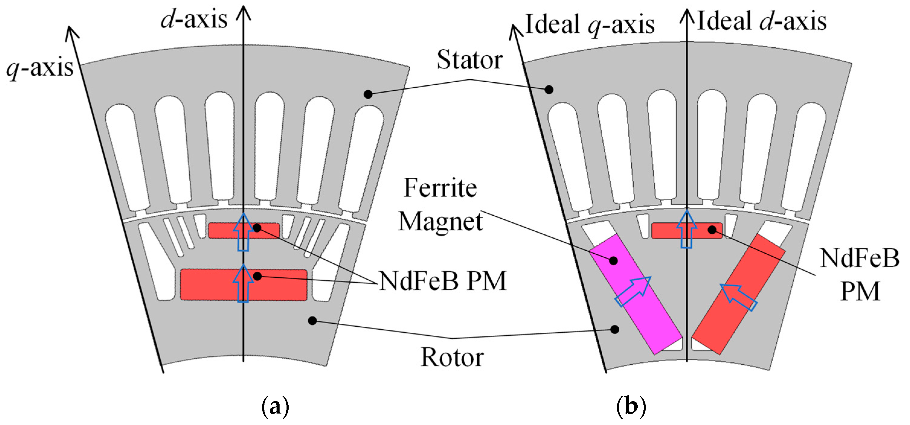
The topologies of the benchmark 2016 BMW i3 IPM machine and the proposed MAS-HPM machine are shown in Figure 1a,b, respectively. The main design parameters are tabulated in Table 1. It should be noted that the proposed machine shares the same inverter power ratings, stator structure, active stack length and air-gap length with the BMW i3 IPM machine. Meanwhile, in order to make a fair comparison, the rare-earth PM usages are identical in the two structures. The main difference between the two machines lies in the fact that two kinds of PM, i.e., low-cost ferrite and high-performance NdFeB magnets, are simultaneously employed in the developed MAS-HPM machine to achieve the MAS effect. The total costs of the magnets are given in Table 1. Due to the additional ferrite magnets, the proposed machine has a slightly higher total cost of magnets than the BMW i3 IPM counterpart. However, compared with the BMW i3 IPM machine, the ratio of the peak torque to the total cost of magnets in the MAS-HPM configuration is increased by about 7.81%, which indicates that the torque capability can be improved by 7.81% at the same cost of magnets.
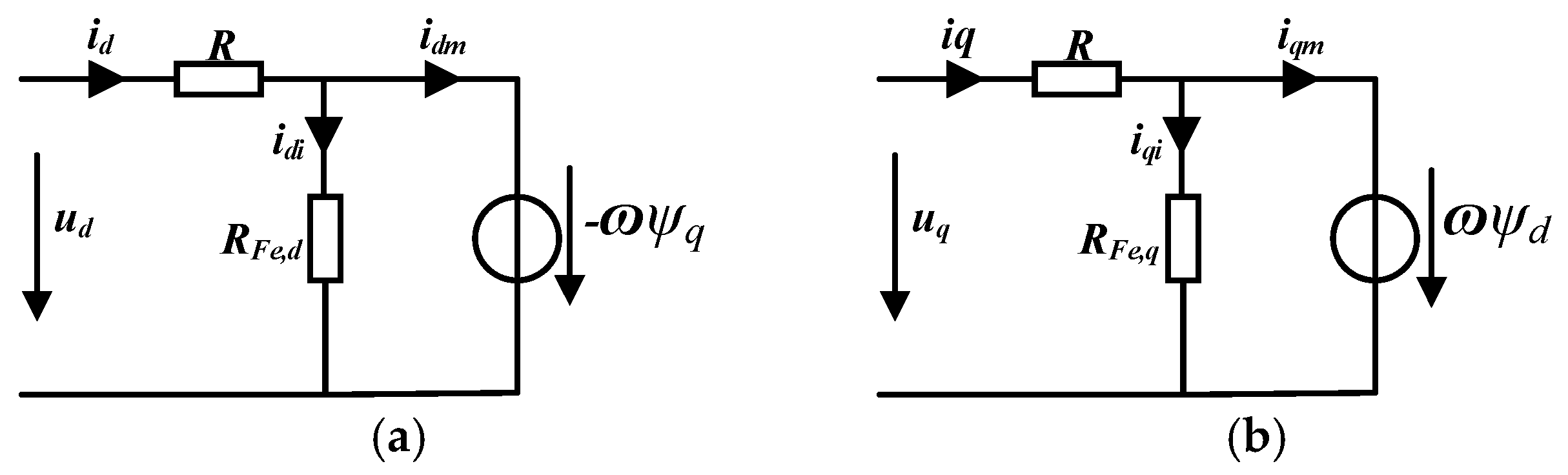
The d and q-axes’ equivalent electrical circuits are illustrated in Figure 2. In the synchronous reference frame, the voltage equations for the PM synchronous machine are expressed as:
where R is the stator resistance, ω is the electric frequency, ψd and ψq are the d and q-axes’ flux linkages, respectively. id and iq are the d and q-axes’ current, respectively.
By the application of Kirchhoff’s voltage and current laws to both d and q-axes, the four equations can be obtained as:
where RFe,d and RFe,q are the iron losses resistances in d and q-axes, respectively. idi and iqi are the iron losses currents in d and q-axes, respectively. idm and iqm are the d and q-axes’ magnetization currents, respectively.
2.2. MAS Principle
The total torque Ttotal of an IPM machine, including the PM torque TPM and the reluctance torque Tr, can be expressed as [23]:
where pr, ψf, is, Ld and Lq are the rotor pole pair number, the PM flux linkage, the phase current and the d- and q-axes’ inductances, respectively. β is the current angle, which is defined as the angle between the phase current and open-circuit back electro-motive force (EMF) [24].
From Equations (3)–(5), it can be found that the optimum current angle for Tr is theoretically twice that for TPM. If the difference between the optimum current angles for maximizing the two kinds of torques can be reduced, the torque capability of the machine will be improved. To achieve this goal, this paper proposes an asymmetrical PM arrangement by employing the HPM configuration, i.e., low-cost ferrite and high-performance NdFeB magnets, which is termed as the MAS effect. In this case, the magnet axis is shifted while the reluctance axis is unchanged due to the symmetrical rotor configuration. Thus, the difference of the current angles γs when both TPM and Tr reach the maximum can be reduced, which can be defined as:
where βR and βPM are the optimum current angles for the reluctance and PM torques, respectively.
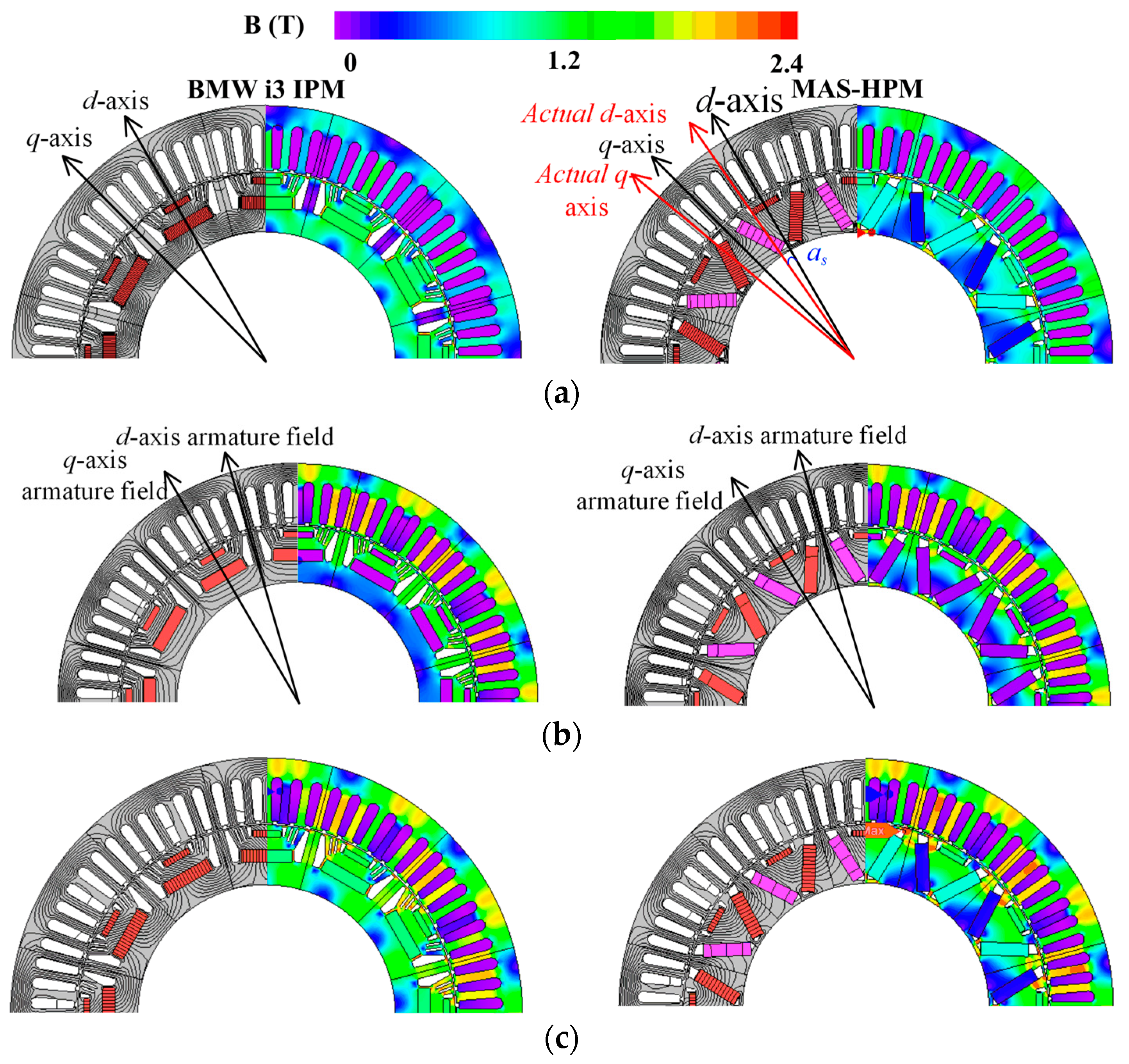
The flux density distributions of the two machines are calculated by finite element analysis (FEA) and illustrated in Figure 3. It can be seen that the d-axis shifted by an angle αs in the proposed machine under the open-circuit condition, as shown in Figure 3a, which confirms the MAS effect. The reluctance d and q-axes are not changed in the two machines, as shown in Figure 3b, which is mainly attributed to the design of the symmetrical flux barriers in the two rotor configurations. The flux density distributions of the two machines at the peak current load condition are given in Figure 3c. Due to dual excited armature windings and PMs, the two machines under the load condition have higher flux densities than at other operating conditions.
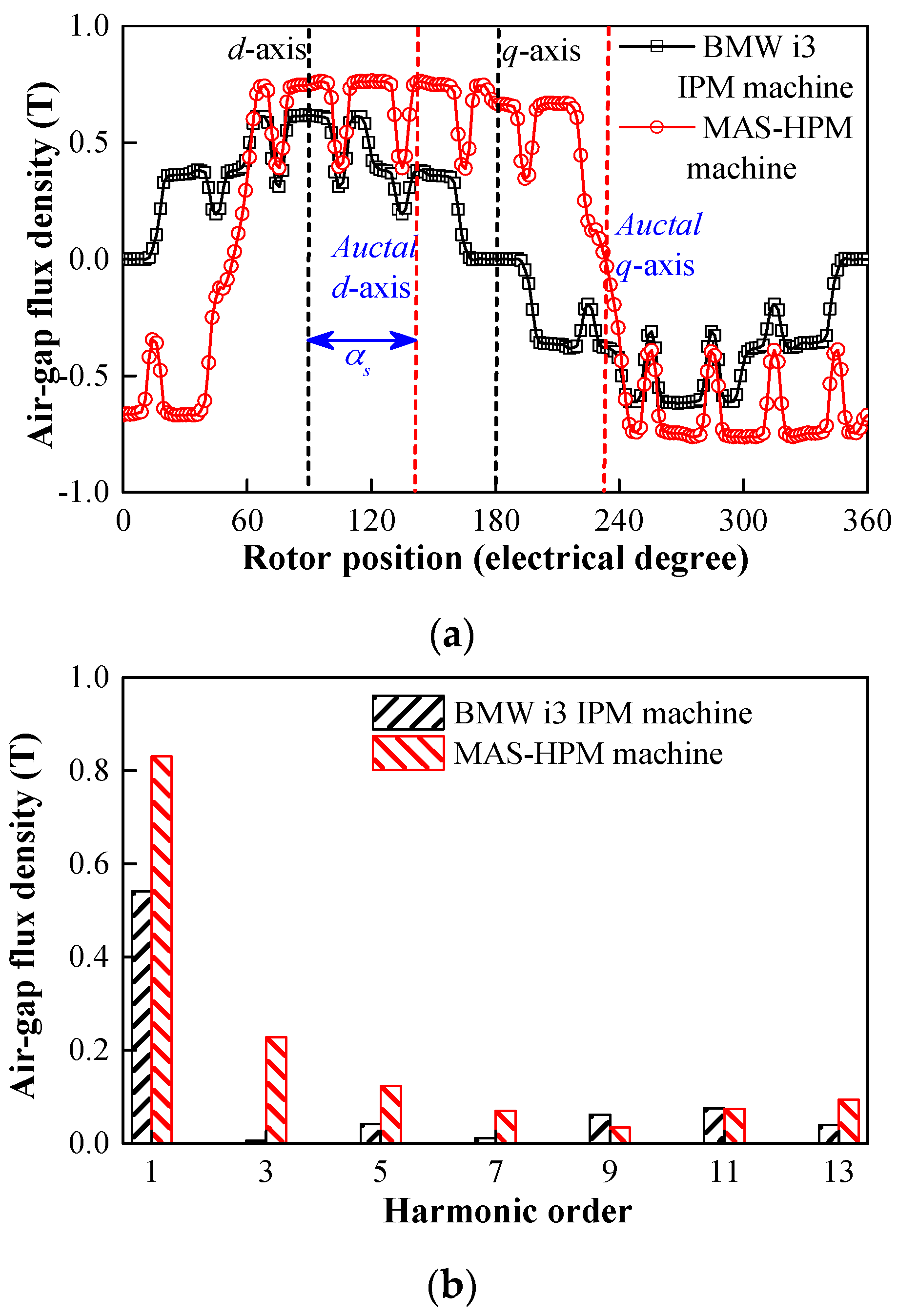
To clearly understand the MAS effect, the open-circuit air-gap flux density waveforms are given in Figure 4. Compared with the d-axis in the BMW i3 IPM machine, the displacement of the actual d-axis occurred in the proposed topology, which means that the magnet and reluctance axes grow closer by using the HPM configuration. Consequently, the resultant current angles for optimizing the reluctance and PM torques are closer, which enables the torque improvement. Moreover, the fundamental amplitude of the air-gap flux density in the MAS-HPM machine are found to be 53.70% higher than that of the BMW i3 IPM machine, as reflected in Figure 4b. Due to the asymmetrical PM configuration, larger high-order harmonics of the air-gap flux density are observed in the MAS-HPM machine.
3. Electromagnetic Performance Comparison
In order to validate the MAS effect, the basic electromagnetic characteristics of the proposed MAS-HPM machine are comparatively studied with those of the BMW i3 IPM machine in this section. In order to reduce the computational time, 1:12 scale models are adopted for the two machines. The simulation time is 2.5 h.
3.1. Open-Circuit Performance
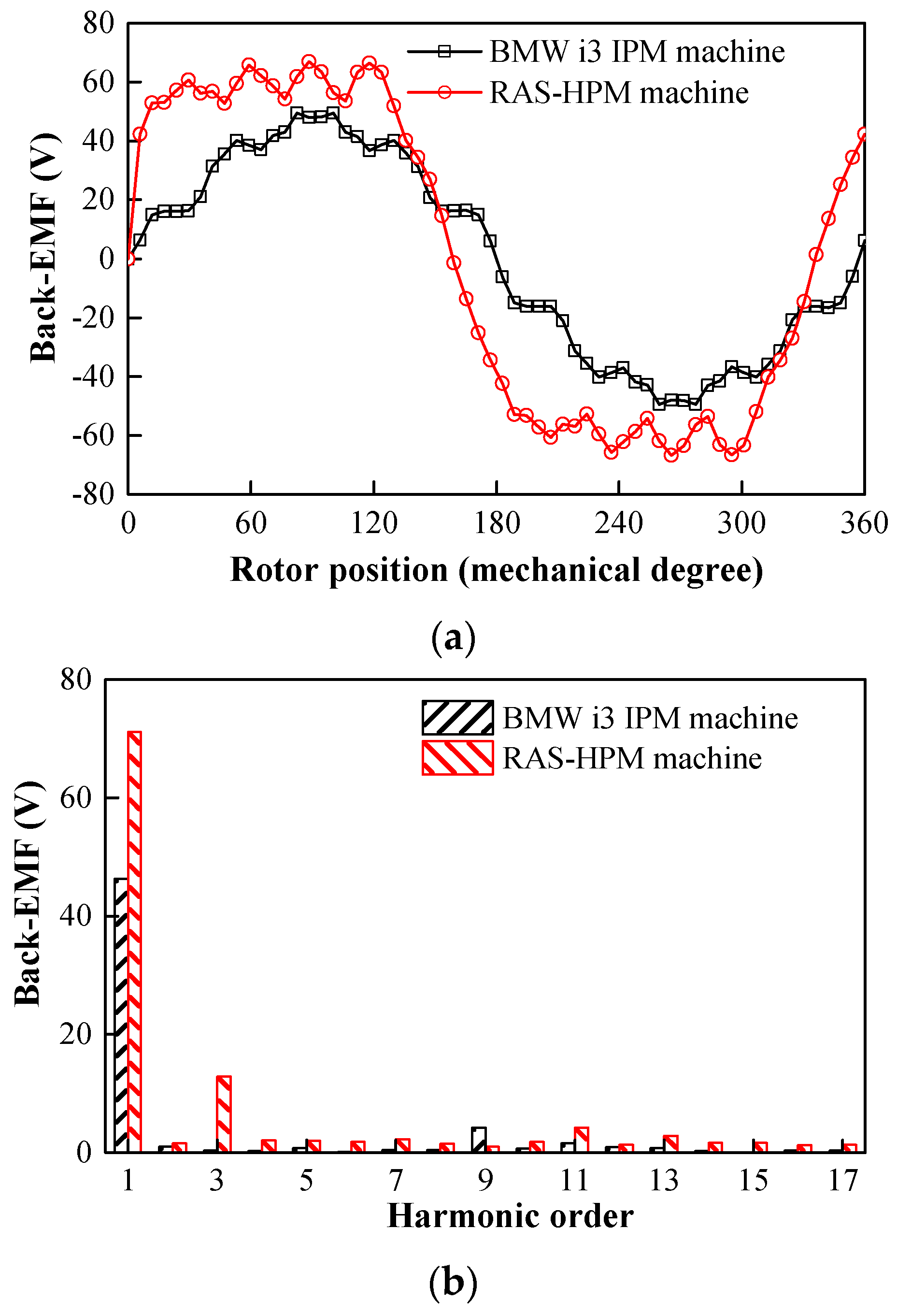
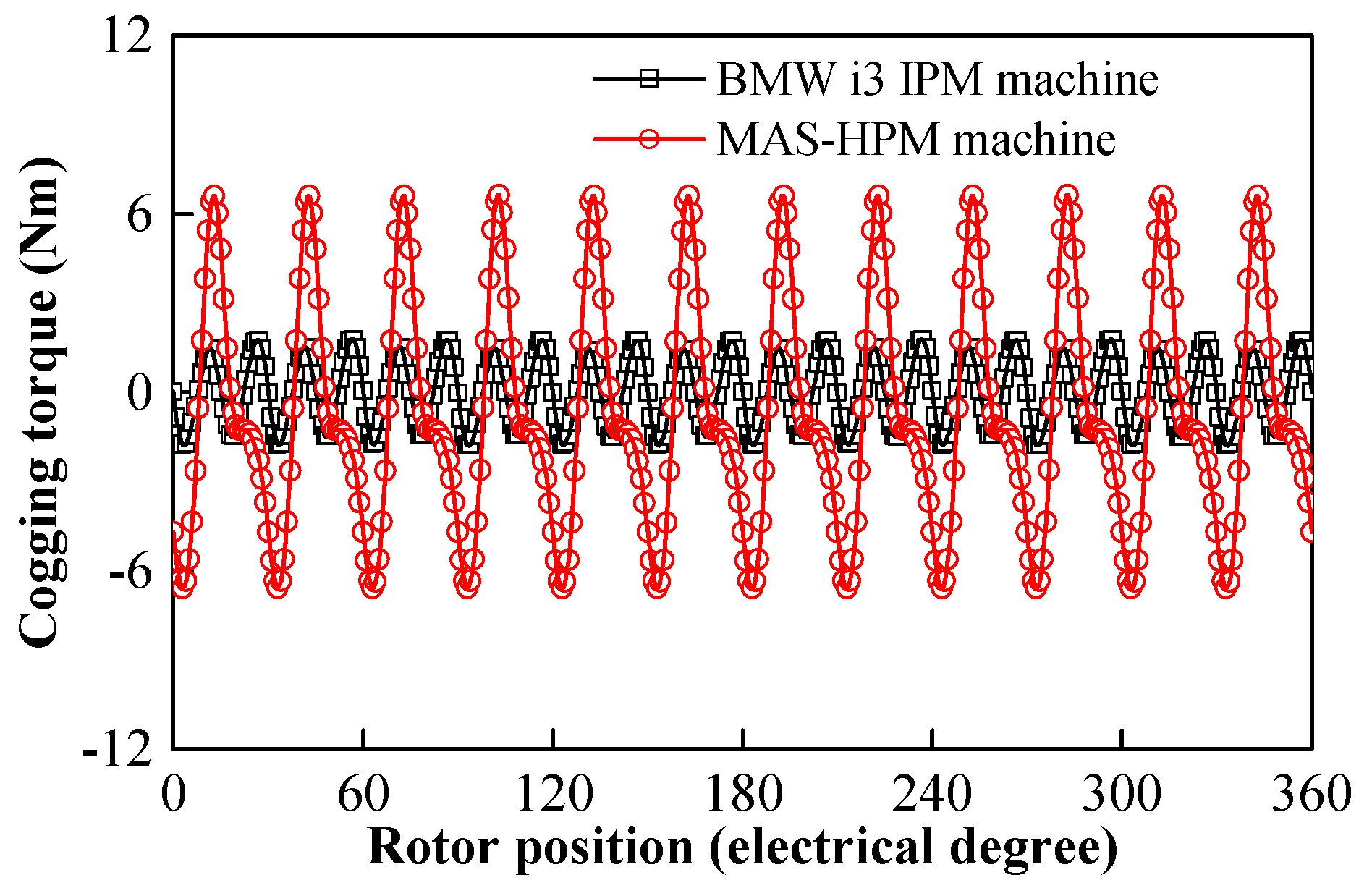
The back EMF waveforms of the two investigated machines are shown in Figure 5. Compared with the BMW i3 IPM machine, the proposed configuration exhibits a 53.54% higher back-EMF fundamental amplitude, which indicates that the magnet torque can be effectively improved by using the HPM configuration. In addition, the cogging torque waveforms of the two machines are shown in Figure 6, which experience the same periods due to the same numbers of stator slots and rotor poles. Because the air-gap flux density contains larger high-order harmonics, as shown in Figure 3b, the MAS-HPM structure has a higher cogging torque amplitude. The ratios of the cogging torque amplitudes to the corresponding peak torque values in BMW i3 IPM and MAS-HPM machines are 0.73% and 2.04%, respectively, which are lower than the acceptable value of 2.5%.
3.2. Torque Characteristics
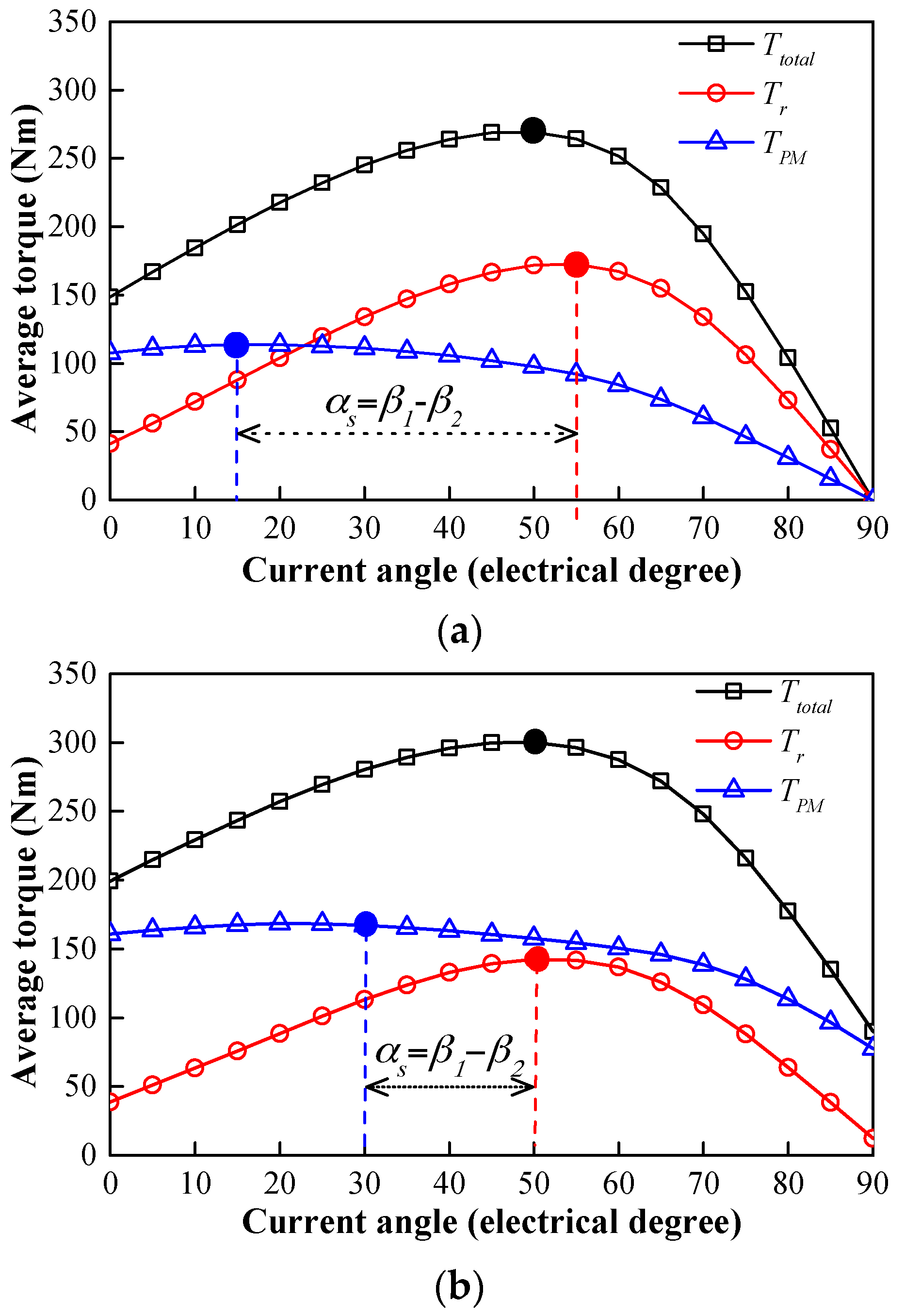
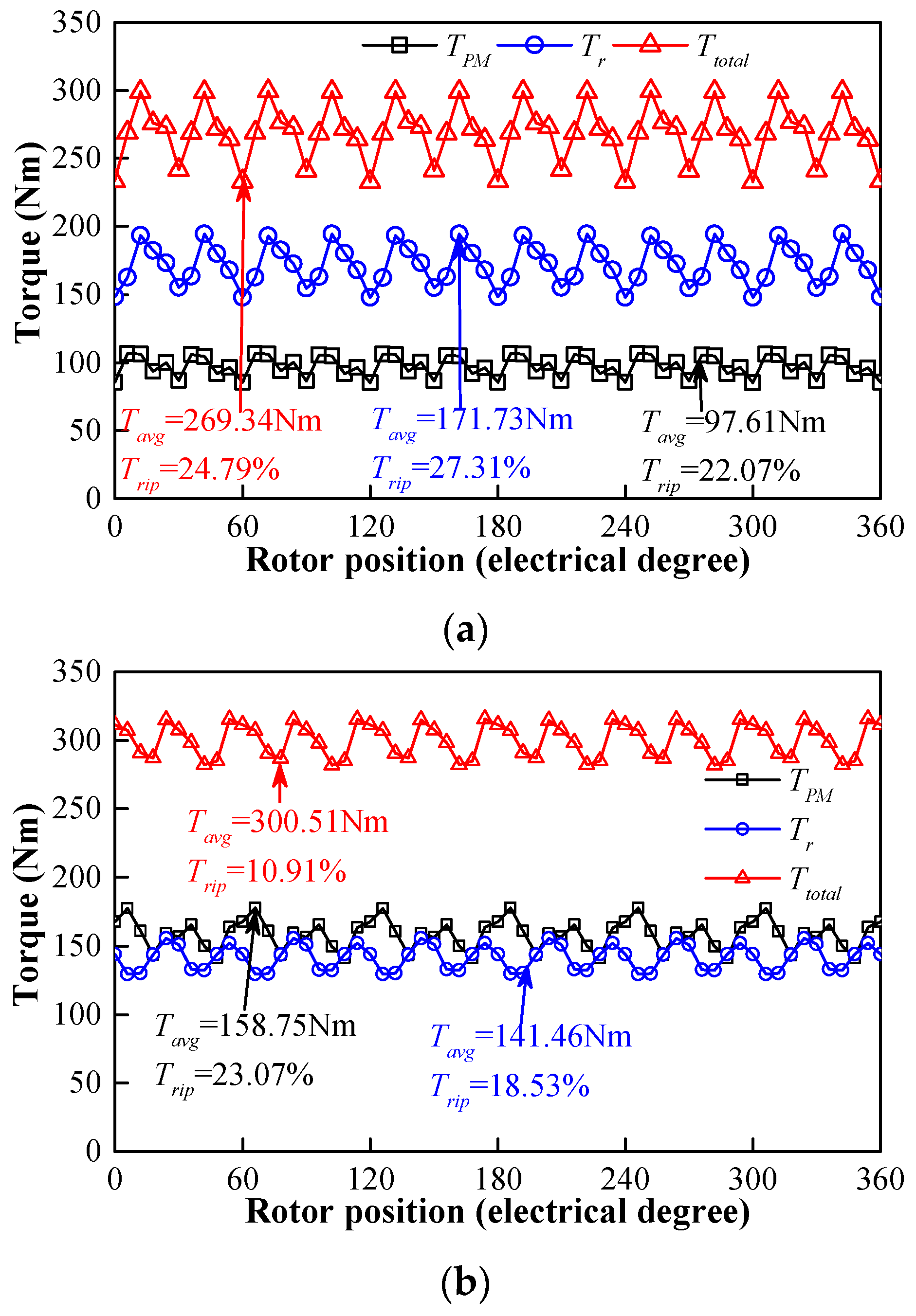
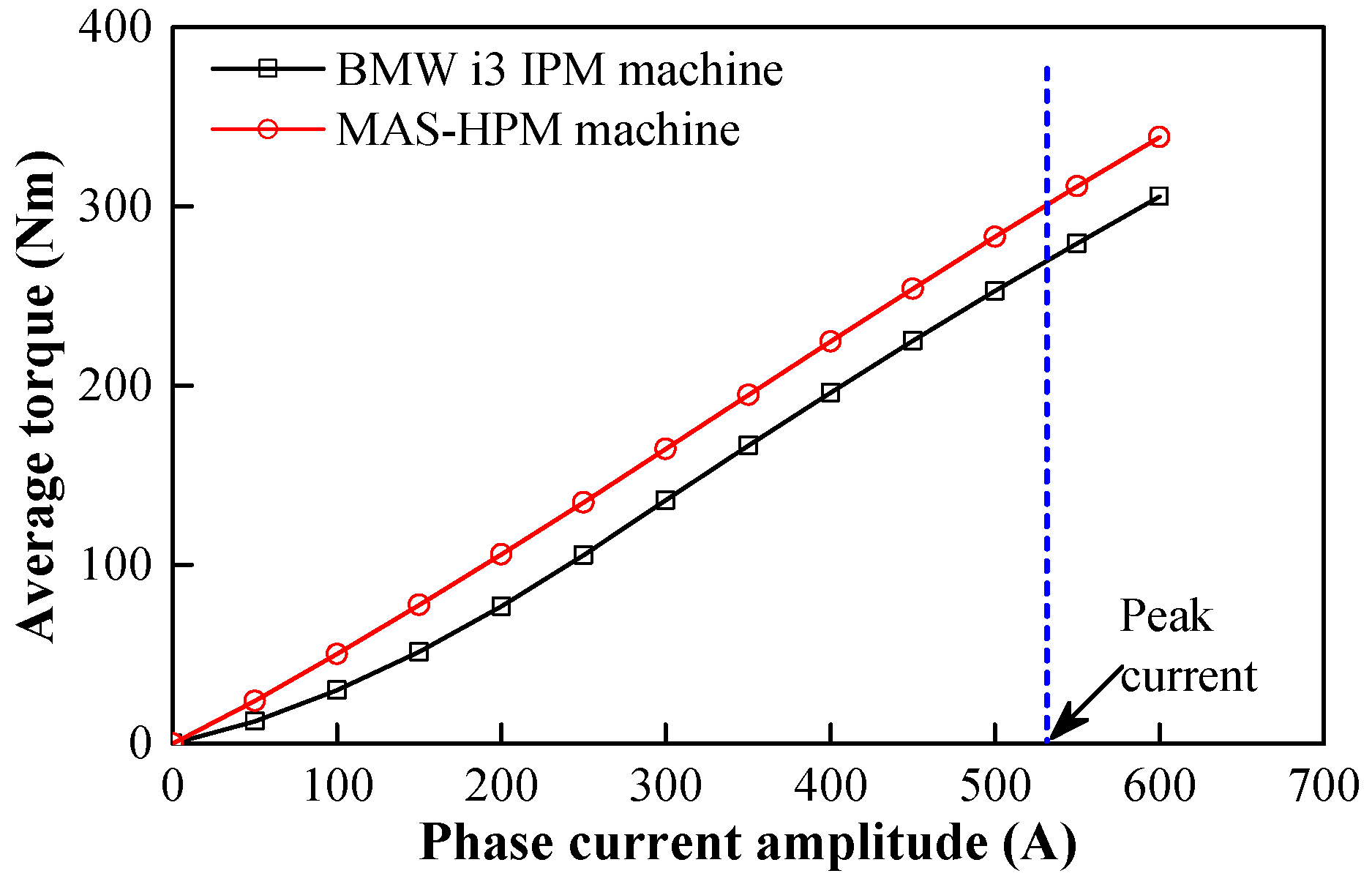
The torque versus current angle characteristics of the two machines are illustrated in Figure 7. The PM and reluctance torques are separated by using the frozen permeability method [25]. It can be seen that the γs of the proposed MAS-HPM machine is smaller than that of the BMW i3 machine. As a result, a higher torque capability can be obtained in the HPM case, as evidenced in Figure 8. Moreover, due to the MAS effect, the ripple patterns of the PM and reluctance torques of the proposed machine are different, which results in a torque ripple offset effect. Hence the HPM configuration exhibits 55.99% lower torque ripple than the BMW i3 IPM machine, as shown in Figure 8b. The average torques versus phase current curves of the two machines are shown in Figure 9. It can be observed that the MAS-HPM machine has a higher torque capability regardless of the applied loads. As a whole, the feasibility of the proposed MAS-HPM design for torque performance improvement is clearly confirmed.
3.3. Torque/Power versus Speed Curves
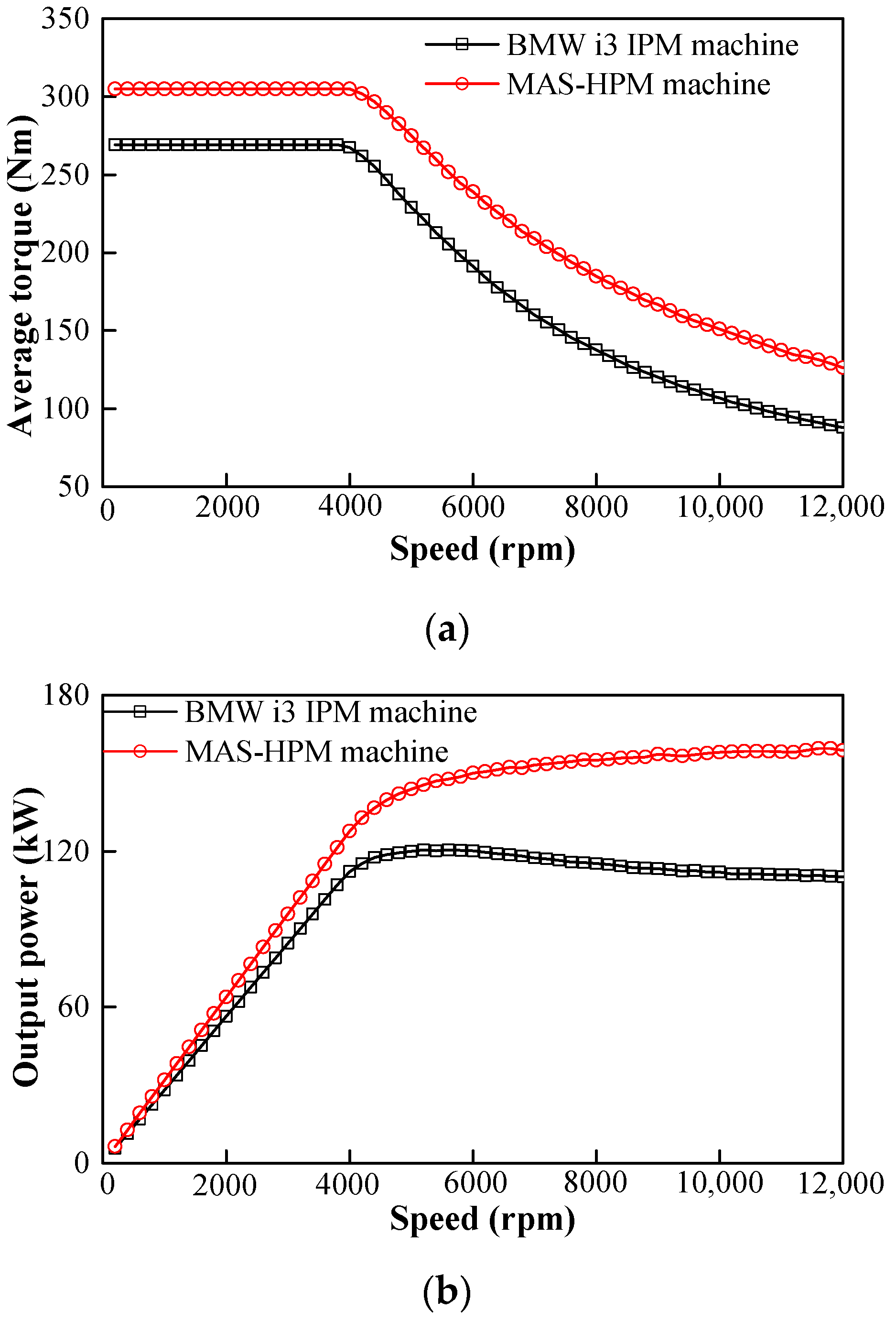
The torque and power versus speed curves of the two machines are illustrated in Figure 10. It can be seen that the MAS-HPM machine exhibits higher torque and power than the BMW i3 IPM machine over the whole operating range, consequently achieving a better high-speed constant power-maintaining capability.
3.4. Irreversible Demagnetization
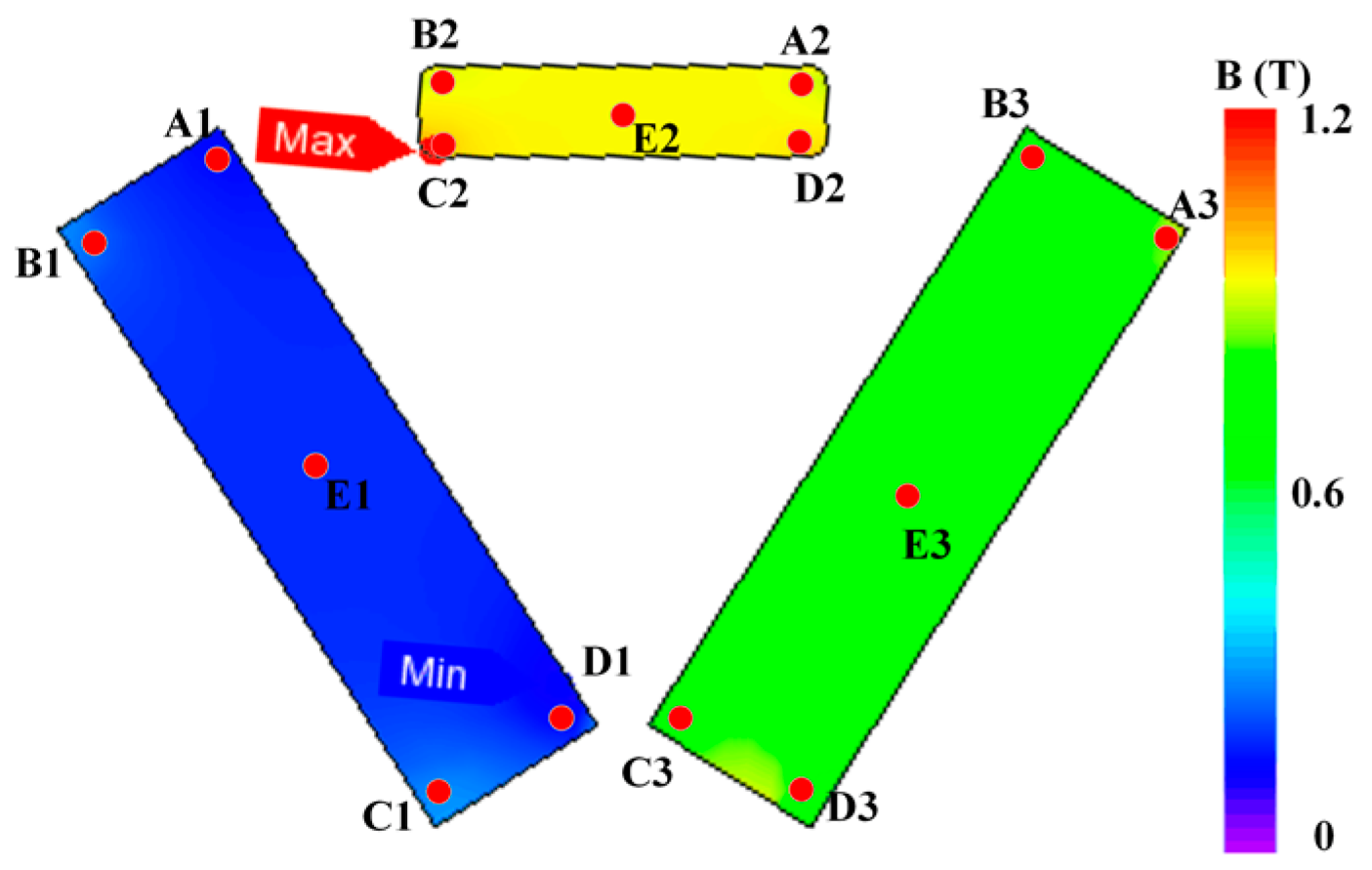
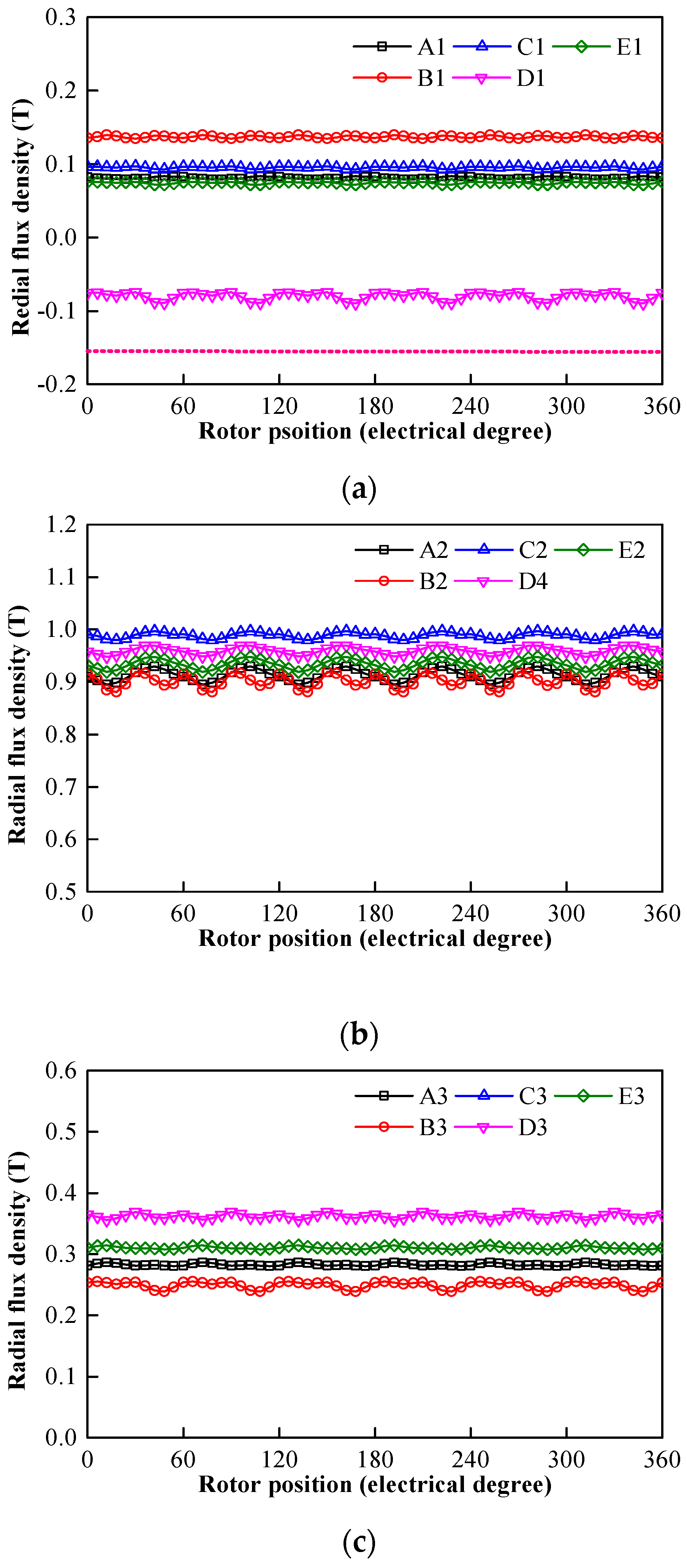
The flux density distributions of the magnets are illustrated in Figure 11. When the working temperature is set as 100 °C, the knee points of ferrite and NdFeB magnets are −0.15 and −0.6 T, respectively. It can be observed that the irreversible demagnetization of ferrite and NdFeB magnets does not occur. In order to quantitatively illustrate the flux density variations of magnets, five typical points are selected in three magnets, as shown in Figure 11. The corresponding flux density variations of the typical five points on magnets are given in Figure 12. It can be seen that the working points of ferrite and NdFeB magnets are greater than the respective knee points, which indicates that good demagnetization withstanding capability can be achieved.
3.5. Rotor Mechanical Analyses
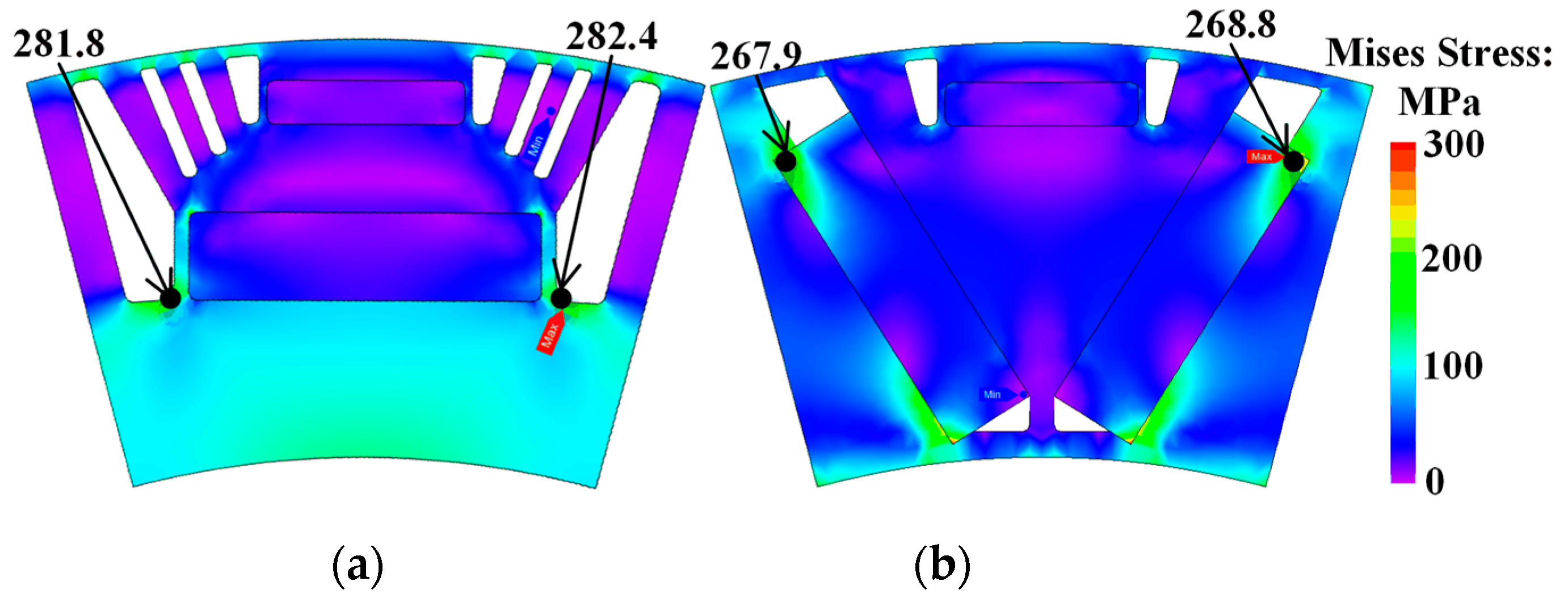
The rotor mechanical strengths of the two machines are investigated at the maximum speed of 12,000 rpm in this section. The von Mises stress maps are shown in Figure 13. It can be observed that the peak stress of the MAS-HPM machine (268.8 MPa) is slightly lower than that of the BMW i3 IPM machine (282.4 MPa), which are both lower than the threshold yield value (396 MPa). Due to the differences in mesh subdivision, it can be observed that the mismatch between the maximal values occurs at the two sides of the symmetrical configurations. However, the difference in stress values between the points of the symmetrical structure is very small and thus negligible, as shown in Figure 13. As a result, it was confirmed that the proposed rotor configuration can withstand a larger centrifugal force at the maximum speed of 12,000 rpm.
3.6. Loss and Efficiency
The two machines have the same stators and windings, which indicates that the same copper losses can be achieved. The iron loss and efficiency are calculated and illustrated in Figure 14 and Figure 15, respectively. The iron loss pi, eddy-current loss pe and hysteresis loss ph in the laminated core are calculated as follows [26]:
where Ke and Kh are the experimental constants obtained by the Epstein frame test of the core material, D is the density of the steel sheets, f is the fundamental frequency, Br, n and Bθ,n are the radial and tangential components of the flux density at each finite element.
The copper loss pcu and efficiency η can be calculated by:
where Ra, I, and ω are the armature winding resistance, the phase current and the mechanical angular velocity, respectively.
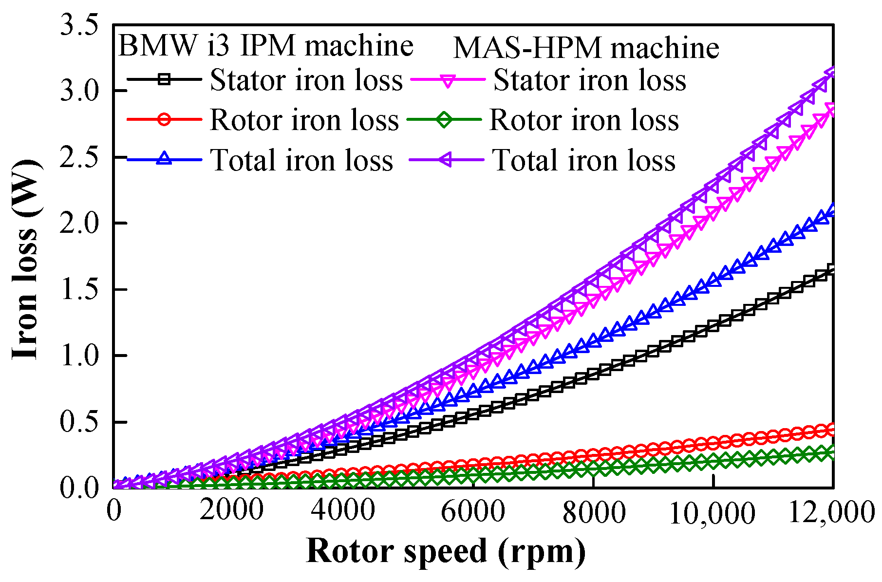
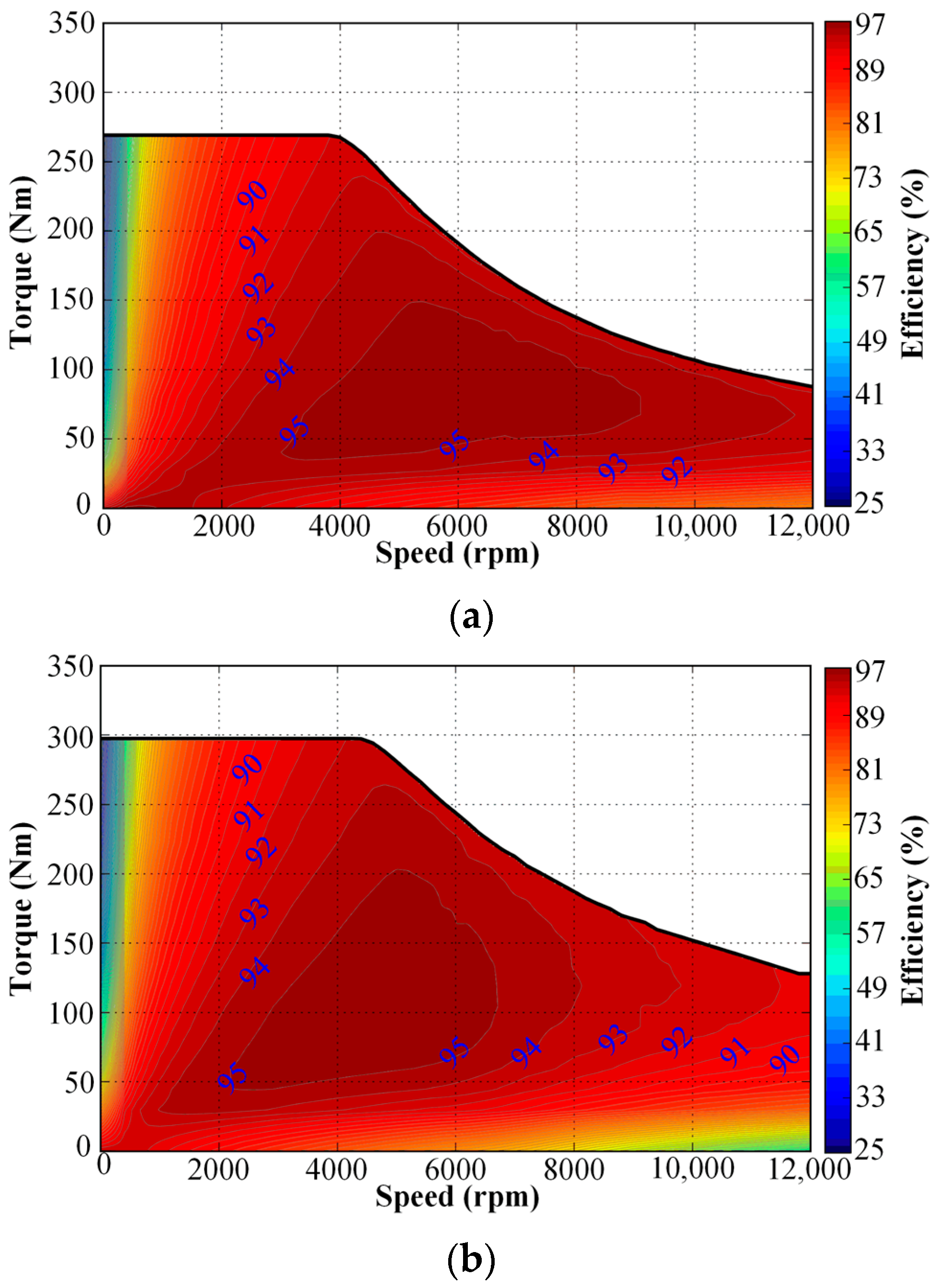
The iron losses of the two machines under different speeds are given in Figure 14. It can be observed that the stator iron losses dominate the total iron losses in both machines at the rated load. The iron losses of the two machines are very close when the speed is lower than 4000 rpm. However, due to higher harmonics, the HPM structure produces a larger iron loss than the BMW i3 IPM machine when the speed exceeds 4000 rpm. Furthermore, the efficiency maps of the two cases are illustrated in Figure 15. The maximum efficiency of the proposed MAS-HPM machine (95.79%) is slightly higher than that of the BMW i3 IPM (95.57%). Due to the higher iron loss in high speed range, the proposed structure shows a relatively lower efficiency when the speed exceeds 10,000 rpm. Nevertheless, the MAS-HPM machine still exhibits a similar operating range when the efficiency is higher than 93%.
4. Conclusions
A novel MAS-HPM machine is proposed to achieve a higher torque capability and a wider high-efficiency operation range for EV applications in this paper. The basic electromagnetic characteristics of the proposed MAS-HPM machine and the benchmark BMW i3 IPM machine are comprehensively investigated and compared by FEA. Due to the MAS effect, the difference between the optimal current angles of maximizing the magnet and reluctance torques is reduced. In addition, it was found that the back-EMF and total torque of the proposed MAS-HPM machine can be effectively improved, compared with the conventional BMW i3 IPM machine. Moreover, the proposed machine shows lower peak mechanical stress, better field-weakening capability, higher peak efficiency and comparable high-efficiency operating range, which confirms the effectiveness of the proposed MAS design concept for performance improvement. However, due to higher harmonics, the proposed MAS-HPM configuration has higher cogging torque and iron losses in a high speed operating range.
Author Contributions
Conceptualization, Y.L. and H.Y.; methodology, Y.L. and H.Y.; software, Y.L. and W.W.; validation, Y.L., H.Y. and H.L., formal analysis, Y.L. and H.Y.; investigation, Y.L. and H.Y.; resources, Y.L. and H.Y.; data curation, Y.L. and H.Y.; writing—original draft preparation, Y.L. and H.Y.; writing—review and editing, Y.L., H.Y., H.L. and S.F.; visualization, Y.L. and H.Y.; supervision, H.Y., H.L., and S.F.; project administration, H.Y.; funding acquisition, H.Y. and H.L.
Funding
This work was jointly supported in part by National Natural Science Foundations of China under Grant 51377036, in part by Natural Science Foundation of Jiangsu Province for Youth (BK20170674), in part by the Fundamental Research Funds for the Central Universities (2242017K41003) and in part by the Postgraduate Research and Practice Innovation Program of Jiangsu Province (KYCX18_0096).
Conflicts of Interest
The authors declare no conflict of interest.
References
- Zhu, Z.Q.; Howe, D. Electrical Machines and Drives for Electric, Hybrid, and Fuel Cell Vehicles. Proc. IEEE 2007, 95, 745–765. [Google Scholar] [CrossRef]
- Burress, T.; Rogers, S.A.; Ozpineci, B. FY 2016 Aannual Progress Report for Electric Drive Technologies Program; Oak Ridge National Laboratory Department of Energy: Oak Ridge, TN, USA, 2016; pp. 196–207. Available online: https://www.energy.gov/sites/prod/files/2017/08/f36/FY16%20EDT%20Annual%20Report_FINAL (accessed on 5 February 2019).
- Chalmers, B.J.; Musaba, L.; Gosden, D.F. Variable-Frequency Synchronous Motor Drives for Electric Vehicles. IEEE Trans. Ind. Appl. 1996, 32, 896–903. [Google Scholar] [CrossRef]
- Chalmers, B.J.; Akmese, R.; Musaba, L. Design and Field-weakening Pperformance of Permanent Magnet/Reluctance Motor with Two-part Rotor. IEE Proc.-Electr. Power Appl. 1998, 145, 133–139. [Google Scholar] [CrossRef]
- Chen, X.; Gu, C.; He, X.; Shao, H. Experimental Research on the ALA+SPM Hybrid Rotor Machine. In Proceedings of the International Conference on Electrical Machines and Systems, Beijing, China, 20–23 August 2011; pp. 1–4. [Google Scholar]
- Yang, H.; Li, Y.; Lin, H.; Zhu, Z.Q.; Lyu, S.; Wang, H.; Fang, S.; Huang, Y. Novel Reluctance Axis Shifted Machines with Hybrid Rotors. In Proceedings of the Energy Conversion Congress and Exposition (ECCE), Cincinnati, OH, USA, 1–5 October 2017; pp. 2362–2367. [Google Scholar]
- Liu, G.; Xu, G.; Zhao, W.; Du, X.; Chen, Q. Improvement of Torque Capability of Permanent-Magnet Motor by Using Hybrid Rotor Configuration. IEEE Trans. Energy Convers. 2017, 32, 953–962. [Google Scholar] [CrossRef]
- Li, Y.; Bobba, D.; Sarlioglu, B. Design and Optimization of a Novel Dual-Rotor Hybrid PM Machine for Traction Application. IEEE Trans. Ind. Electron. 2018, 65, 1762–1771. [Google Scholar] [CrossRef]
- Zhao, W.; Chen, D.; Lipo, T.A.; Kwon, B. Performance Improvement of Ferrite-Assisted Synchronous Reluctance Machines Using Asymmetrical Rotor Configurations. IEEE Trans. Magn. 2015, 51, 8108504. [Google Scholar] [CrossRef]
- Randi, S.A.; Astier, S. Parameters of Salient Pole Synchronous Motor Drives with Two-Part Rotor to Achieve a Given Constant Power Speed Range. In Proceedings of the IEEE 32nd Annual Power Electronics Specialists Conference, Vancouver, BC, Canada, 17–21 June 2001; pp. 1673–1678. [Google Scholar]
- Winzer, P.; Doppelbauer, M. Theoretical Analysis of Synchronous Machines with Displaced Reluctance Axis. In Proceedings of the International Conference on Electrical Machines (ICEM), Berlin, Germany, 2–5 September 2014; pp. 641–647. [Google Scholar]
- Winzer, P.; Doppelbauer, M. Comparison of Synchronous Machine Designs with Displaced Reluctance Axis Considering Losses and Iron Saturation. In Proceedings of the IEEE International Electric Machines & Drives Conference (IEMDC), Coeur d’Alene, ID, USA, 10–13 May 2015; pp. 1801–1807. [Google Scholar]
- Alsawalhi, J.Y.; Sudhoff, S.D. Effects of Positioning of Permanent Magnet Axis Relative to Reluctance Axis in Permanent Magnet Synchronous Machines. In Proceedings of the IEEE Power and Energy Conference at Illinois (PECI), Champaign, IL, USA, 20–21 February 2015; pp. 1–8. [Google Scholar]
- Alsawalhi, J.Y.; Sudhoff, S.D. Design Optimization of Asymmetric Salient Permanent Magnet Synchronous Machines. IEEE Trans. Energy Convers. 2016, 31, 1315–1324. [Google Scholar] [CrossRef]
- Zhu, X.; Zhang, X.W.C.; Wang, L.; Wu, W. Design and analysis of a spoke-type hybrid permanent magnet motor for electric vehicles. IEEE Trans. Magn. 2017, 53, 8208604. [Google Scholar] [CrossRef]
- Jeong, C.L.; Hur, J. Design technique for PMSM with hybrid type permanent magnet. In Proceedings of the IEEE International Electric Machines and Drives Conference (IEMDC), Miami, FL, USA, 21–24 May 2017; pp. 1–6. [Google Scholar]
- Li, G.J.; Zhu, Z.Q. Hybrid excited switched flux permanent magnet machines with hybrid magnets. In Proceedings of the 8th International Conference on Power Electronics, Machines and Drives (PEMD 2016), Glasgow, UK, 19–21 April 2016; pp. 1–6. [Google Scholar]
- Yang, H.; Lin, H.; Zhu, Z.Q.; Wang, D.; Fang, S.; Huang, Y. A variable-flux hybrid-PM switched-flux memory machine for EV/HEV applications. IEEE Trans. Ind. Appl. 2016, 52, 2203–2214. [Google Scholar] [CrossRef]
- Yang, H.; Zhu, Z.Q.; Lin, H.; Zhan, H.L.; Hua, H.; Zhuang, E.; Fang, S.; Huang, Y. Hybrid-excited switched-flux hybrid magnet memory machines. IEEE Trans. Magn. 2016, 52, 8202215. [Google Scholar] [CrossRef]
- Yang, H.; Zhu, Z.Q.; Lin, H.; Wu, D.; Hua, H.; Fang, S.; Huang, Y. Novel high-performance switched flux hybrid magnet memory machines with reduced rare-earth magnets. IEEE Trans. Ind. Appl. 2016, 52, 3901–3915. [Google Scholar] [CrossRef]
- Yang, H.; Zhu, Z.Q.; Lin, H.; Fang, S.; Huang, Y. Synthesis of hybrid magnet memory machines having separate stators for traction applications. IEEE Trans. Veh. Technol. 2018, 67, 183–195. [Google Scholar] [CrossRef]
- Yang, H.; Lin, H.; Zhu, Z.Q.; Fang, S.; Huang, Y. A dual-consequent-pole Vernier memory machine. Energies 2016, 9, 134. [Google Scholar] [CrossRef]
- Jahns, T.M.; Kliman, G.B.; Neumann, T.W. Interior permanent-magnet synchronous motors for adjustable-speed drives. IEEE Trans. Ind. Appl. 1986, IA-22, 738–747. [Google Scholar] [CrossRef]
- Gieras, J.F. Permanent Magnet Motor Technology: Design and Application, 3rd ed.; CRC Press: Boca Raton, FL, USA, 2009. [Google Scholar]
- Chu, W.Q.; Zhu, Z.Q. Average torque separation in permanent magnet synchronous machines using frozen permeability. IEEE Trans. Magn. 2013, 49, 1202–1210. [Google Scholar] [CrossRef]
- Yamazaki, K.; Abe, A. Loss investigated of interior permanent-magnet motors considering carrier harmonics and magnet eddy currents. IEEE Trans. Ind. Appl. 2009, 45, 659–665. [Google Scholar] [CrossRef]
Figure 1.
Machine topologies. (a) BMW i3 interior permanent magnet (IPM) machine. (b) The proposed magnet-axis-shifted hybrid permanent magnet (MAS-HPM) machine.
Figure 1.
Machine topologies. (a) BMW i3 interior permanent magnet (IPM) machine. (b) The proposed magnet-axis-shifted hybrid permanent magnet (MAS-HPM) machine.

Figure 2.
d and q-axes’ equivalent electrical circuits. (a) d-axis. (b) q-axis.

Figure 3.
Flux density distributions of the two machines. (a) Open-circuit. (b) Reluctance axis with only armature windings excited. (c) Peak current load condition.
Figure 3.
Flux density distributions of the two machines. (a) Open-circuit. (b) Reluctance axis with only armature windings excited. (c) Peak current load condition.

Figure 4.
Open-circuit air-gap flux density. (a) Waveforms. (b) Spectra.

Figure 5.
Back electro-motive force (EMF) waveforms at 3000 rpm. (a) Waveforms. (b) Spectra.

Figure 6.
Cogging torque waveforms.

Figure 7.
Torque versus current angle characteristics. (a) BMW i3 IPM machine. (b) MAS-HPM machine.

Figure 8.
Steady torque. (a) BMW i3 IPM machine. (b) MAS-HPM machine.

Figure 9.
Average torque versus phase current curves.

Figure 10.
(a) Torque–speed curves. (b) Power–speed curves. (Irms = 375 A, Udc = 360 V).

Figure 11.
Flux density distributions of ferrite and NdFeB magnets.

Figure 12.
Variations of the working points of the five points on the ferrite and NdFeB magnets. (a) Ferrite magnet. (b) First-layer NdFeB magnet. (c) Second-layer NdFeB magnet.
Figure 12.
Variations of the working points of the five points on the ferrite and NdFeB magnets. (a) Ferrite magnet. (b) First-layer NdFeB magnet. (c) Second-layer NdFeB magnet.

Figure 13.
Rotor von Mises stress distributions at the maximum speed (12,000 rpm). (a) BMW i3 IPM machine. (b) MAS-HPM machine.
Figure 13.
Rotor von Mises stress distributions at the maximum speed (12,000 rpm). (a) BMW i3 IPM machine. (b) MAS-HPM machine.

Figure 14.
Iron losses versus speed curves.

Figure 15.
Efficiency maps. (a) BMW i3 IPM machine. (b) MAS-HPM machine.


Table 1.
Main design parameters of the machines.
| Items | BMW i3 IPM | MAS-HPM |
|---|---|---|
| Stator slot number | 72 | |
| Rotor pole pair number | 6 | |
| Stator outer radius (mm) | 121 | |
| Air-gap length (mm) | 0.7 | |
| Rotor outer radius (mm) | 89.3 | |
| Active stack length (mm) | 132 | |
| Peak current (A) | 530 | |
| Steel grade | TKM330-35 | |
| NdFeB grade | N35EH | |
| Ferrite magnet grade | - | AC-12 |
| NdFeB PM volume (mm3) | 24,816 | |
| Ferrite magnet volume (mm3) | - | 19,565 |
| Total cost of magnets (¥) | 51.3 | 53.1 |
| Peak torque (Nm) | 269.34 | 300.51 |
| Peak torque/total cost of magnets (Nm/¥) | 5.25 | 5.66 |
| Working temperature (°C) | 100 | |
© 2019 by the authors. Licensee MDPI, Basel, Switzerland. This article is an open access article distributed under the terms and conditions of the Creative Commons Attribution (CC BY) license (http://creativecommons.org/licenses/by/4.0/).
Share and Cite
MDPI and ACS Style
Li, Y.; Yang, H.; Lin, H.; Fang, S.; Wang, W. A Novel Magnet-Axis-Shifted Hybrid Permanent Magnet Machine for Electric Vehicle Applications. Energies 2019, 12, 641. https://0-doi-org.brum.beds.ac.uk/10.3390/en12040641
AMA Style
Li Y, Yang H, Lin H, Fang S, Wang W. A Novel Magnet-Axis-Shifted Hybrid Permanent Magnet Machine for Electric Vehicle Applications. Energies. 2019; 12(4):641. https://0-doi-org.brum.beds.ac.uk/10.3390/en12040641
Chicago/Turabian StyleLi, Ya, Hui Yang, Heyun Lin, Shuhua Fang, and Weijia Wang. 2019. "A Novel Magnet-Axis-Shifted Hybrid Permanent Magnet Machine for Electric Vehicle Applications" Energies 12, no. 4: 641. https://0-doi-org.brum.beds.ac.uk/10.3390/en12040641
Note that from the first issue of 2016, this journal uses article numbers instead of page numbers. See further details here.