Low-Cost Position Sensorless Speed Control of PMSM Drive Using Four-Switch Inverter


Department of Electrical and Electronics Engineering, Istanbul Okan University, 34959 Istanbul, Turkey
*
Author to whom correspondence should be addressed.
†
These authors contributed equally to this work.
Energies 2019, 12(4), 741; https://0-doi-org.brum.beds.ac.uk/10.3390/en12040741
Submission received: 19 January 2019
/
Revised: 10 February 2019
/
Accepted: 19 February 2019
/
Published: 23 February 2019
(This article belongs to the Section F: Electrical Engineering)
Abstract
:A low-cost position sensorless speed control method for permanent magnet synchronous motors (PMSMs) is proposed using a space vector PWM based four-switch three-phase (FSTP) inverter. The stator feedforward -axes voltages are obtained for the position sensorless PMSM drive. The q-axis current controller output with a first order low-pass filter formulates the rotor speed estimation algorithm in a closed-loop fashion similar to PLL (Phase Lock Loop) and the output of the d-axis current controller acts as the derivative representation in the stator feedforward voltage equation. The proposed method is quite insensitive to multiple simultaneous parameter variations such as rotor flux linkage and stator resistance due to the dynamic effects of the PI current regulator outputs that are used in the stator feedforward voltages with a proper value of K gain in the q-axis stator voltage equation. The feasibility and effectiveness of the proposed position sensorless speed control scheme for the PMSM drive using an FSTP inverter are verified by simulation and experimental studies.
1. Introduction
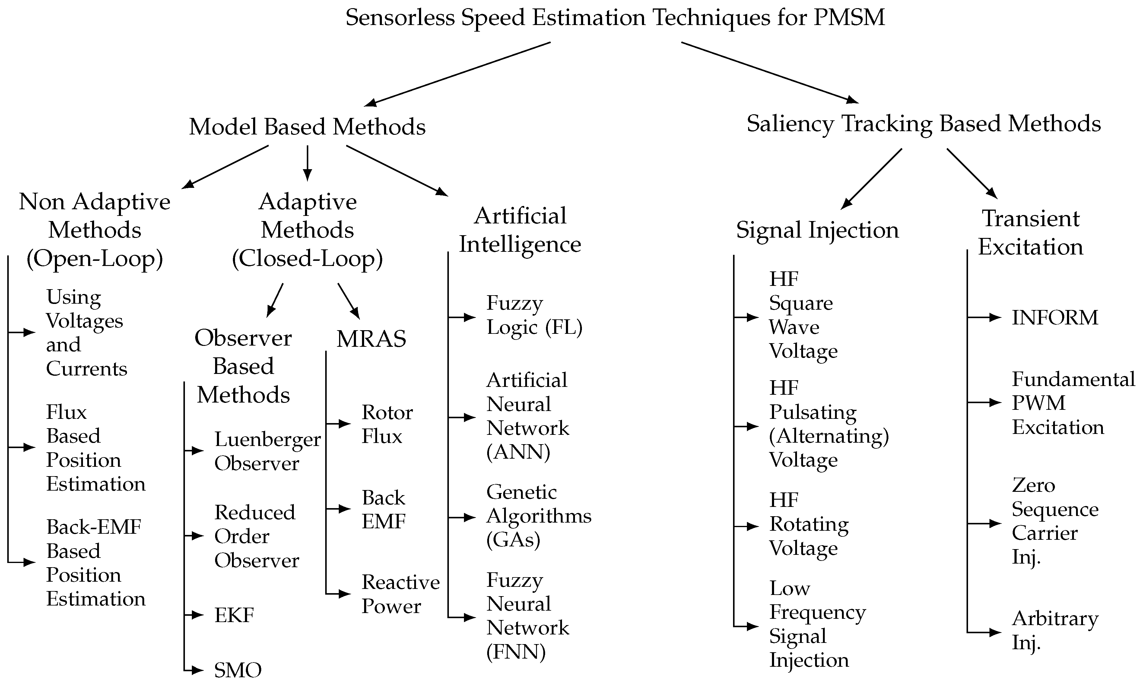
Permanent magnet synchronous motors (PMSMs) with sinusoidal shape back-electromotive force (EMF) require precise position sensors such as an optical encoder and a resolver for field-oriented control (FOC). However, attaching these position sensors to the rotor is associated with cost, space, additional wiring, mechanical burden, weight, noise interference and reliability. Therefore, there is a motivation to eliminate position sensors from the PMSM drive and operate it as “sensorless” or “encoderless”. Although the position sensor is eliminated for sensorless control, the rotor position must be determined only by measured electrical quantities (such as motor currents, inverter direct current (DC)-link voltage, voltages at the motor terminals, etc.). Therefore, current and/or voltage sensors are required to achieve a position sensorless PMSM drive scheme. There are different techniques for sensorless operation of permanent magnet synchronous motors and they are divided into two main groups: (1) model-based methods and (2) saliency and signal injection methods. Sensorless operation of machine model-based methods at zero and low speed is problematic due to motor parameter sensitivity, initial rotor position error, DC drift and flux integration issues, measurement errors of stator current and voltage, inverter and machine nonlinearity. Since model-based methods rely on the amplitude of back-EMF, which is proportional to the rotor speed, these techniques fail in zero and low-speed regions. Therefore, model-based sensorless methods present good results only in the middle and high-speed regions. Saliency and signal injection techniques do not require back-EMF information; therefore, improved zero and low speed performance along with less parameter dependencies are achieved even under heavy load conditions. However, these sensorless techniques are difficult to implement and produce high audible noise, extra losses, current harmonics, torque ripples, transient disturbances and vibration. The detailed classifications of the sensorless control methods are depicted in Figure 1 [1,2,3,4,5,6,7]. Recently, improvements in model-based and signal injection methods for PMSM drives have been investigated in the literature [8,9,10,11,12,13,14,15]. To suppress the unwanted audible noises in the signal injection methods, pseudo-random high-frequency signal injection (HFSI) method is proposed as an alternative to the classical HFSI technique [8,9]. To eliminate the harmonics and improve the estimation of the rotor position in the model-based sensorless control methods, adaptive linear neural (ADALINE) network-based filter is proposed in [10]. In [11], a robust adaptive sliding-mode observer (SMO) with an online inverter nonlinearity compensation method is proposed to reduce the chattering effect of SMO. The proposed method improves the dynamic and steady-state performance of the surface mounted PMSM drive in a low speed region.
Hybrid methods become an alternative approach to improve the issues observed in the model-based sensorless schemes. The combination of sliding mode observer (SMO) and neural networks (NNs) is proposed as an angle compensator to improve the starting and low speed performance of the PMSM drive in [12]. Adaptive synchronous-requency tracking-mode observer (SFTO) which is a combination of SMO and model reference adaptive system (MRAS) is investigated for a surface mounted PMSM drive in [13]. In [14], a highly accurate rotor position and speed estimation are achieved by eliminating the influence of harmonic components caused by torque fluctuations at high and low speed regions. Two novel nonlinear rotor flux observers, second-order generalized integral flux observer (SOIFO) and second-order SOIFO are proposed instead of a classical pure integrator and Low-Pass Filter (LPF) to eliminate the offset and harmonics in the estimated rotor flux. Therefore, low speed operation of surface mounted PMSM is improved even under resistance variation. In addition, the wide speed range sensorless control can be achieved by combining signal injection methods with machine model-based methods [5]. Hybrid methods are used both with signal injection and model-based methods where seamless transition is performed by switching from a signal injection method to a model-based method above a certain speed threshold. The hybrid seamless control method with a dual-position tracking observer in conjunction with the signal injection and sliding mode observer (SMO) is proposed and evaluated in [15]. However, operation of a wide range of sensorless speed control is achieved, and hybrid sensorless control systems increase the complexity of the overall control system.
In many applications where, especially, low power is demanded such as in consumer products and light electric vehicles, the development of a reduced cost three-phase inverter is essential to decreasing the overall drive cost along with removing the position sensor. The overall price of the three-phase inverter is mainly determined by the number of semiconductor switches. A low-cost inverter topology with a reduced number of switching devices was first presented for an induction machine drive system in [16] as an FSTP inverter in which one of the three-phase windings is connected to the center-tap of the two DC-link capacitors and a comparable performance is achieved to the conventional six-switch three-phase (SSTP) inverter. With this modification, the FSTP voltage source inverter (VSI) topology generates only four non-zero active space vectors without any non-zero vectors in the plane, as opposed to six active and two zero voltage space vectors in the SSTP VSI counterpart and it is acknowledged as the standard reduced switch inverter topology for three-phase alternative current (AC) drives in the literature.
FSTP inverter control topologies have been adapted to both sensored and sensorless PMSM and brushless DC (BLDC) drives in [17,18,19,20,21,22,23,24,25,26,27,28,29,30,31,32,33,34,35,36,37,38,39,40,41,42,43,44,45,46,47,48,49,50,51,52,53,54,55,56,57,58,59,60,61,62,63,64]. FSTP inverter-based BLDC drive is firstly introduced in [17]. The improvement in speed control performance of [17] is achieved in [18]. In Ref. [19], one of the first attempts of PMSM speed control using an FSTP inverter is performed and compared with an SSTP inverter. In Ref. [20], the BLDC motor with three hall-effect position sensors driven by an FSTP inverter based on a novel current controlled PWM strategy with six commutation modes is proposed. To achieve low-cost sensorless BLDC position control, utilizing crossing detection of the two active phase voltage waveforms with an asymmetric voltage PWM method based on [20] is presented in [21]. In Refs. [22,23,24,25], sensorless control methods for a BLDC drive using an FSTP inverter are reported. The position sensorless control of PMSM driven by an FSTP inverter is introduced in [26,27,28]. In [29], a direct torque control (DTC)-based BLDC motor driven by an FSTP inverter that employed a novel optimum switching table which enables the independent simultaneous control of the electromagnetic torques developed by the phases connected to the inverter legs without requiring explicit stator flux control is achieved. The operation of an FSTP inverter resembles the faulty one-leg of a traditional SSTP inverter. Recent research has focused on the reliability and fault tolerance of an SSTP inverter under faulty one-leg conditions to maintain the stable operation of the overall drive scheme. In Ref. [30], the proper operation of an induction motor driven by an SSTP inverter under a short-circuit fault in one-leg is accomplished without significant disturbance using a proposed fault isolation topology in which the inverter is reconfigured from six switches to only four switches. The faulty condition of an SSTP inverter resembling the operation of an FSTP inverter are investigated for PMSM drives using FOC and DTC schemes in [31,32,33,34,35,36,37,38]. Minimization of torque and current ripples incorporating space vector pulse width modulation (SVPWM) have been investigated for FSTP inverters. In the FSTP inverter, one phase is always attached to the uncontrolled center tap of the two DC-link capacitors; therefore, current waveforms are distorted and unbalanced. Compensation strategies for PMSM and BLDC drives are employed to overcome the current and torque distortion and unbalancing issues of FSTP inverter in [39,40,41,42,43,44,45]. Moreover, there have been efforts to reduce the number of current sensors from two to one in FSTP inverter driven PMSM and BLDC drives in [25,46,47]. Intelligent control methods such as fuzzy-logic and ANN type controller strategies have been proposed for FSTP driven PMSM and BLDC drives in [48,49,50,51,52]. BLDC drives using FSTP inverters with power factor correction (PFC) have been presented in [53,54].
There are several advantages of an FSTP inverter compared to traditional SSTP inverter: although each switch rating in FSTP inverter is higher than the one in the SSTP inverter, the price of total number of switches in FSTP inverter is reduced compared to the one in the SSTP inverter, therefore cost and space are minimized due to the reduction of the number in the semiconductor switches and freewheeling diodes; there are only two driving circuits, therefore complexity of drive and control circuitry are reduced which lowers the overall cost of the drive; due to the elimination of the semiconductor switches, with no change in the amplitude of DC-link voltage, conduction and switching losses are reduced by 1/3; since there is a smaller number of semiconductor switches, the reliability of the converter increases; maximum common mode voltage is only 2/3 of SSTP inverters. Unit cost per kW is targeted to be $13.7 at 2022 R&D targets [65]. Housing and Heatsink costs represent 10% of the total cost. When the cooling system needs to be reduced by 1/3 in the developed system, the heating requirement is around 15% more compared to the six-switch inverter because of the power ratio. In this case, a cost of 1.04 $/kW is achieved. A larger capacitor is required due to the peak in voltage. For this reason, the total cost of the capacitor, which is 14%, is 2.877 $/kW. In signal processing and power solid-state circuitry, a reduction of 1/3 is achieved. The cost is 2.74 $/kW for the signal circuit and 3.1967 $/kW for the power modules. The realized system cost is 12.054 $/kW. Given the 2022 targets, total cost reduction of 12.08% is achieved. Due to the above-mentioned benefits, FSTP inverter topology has been implemented in many low to medium power industrial applications ranging from servo to traction.
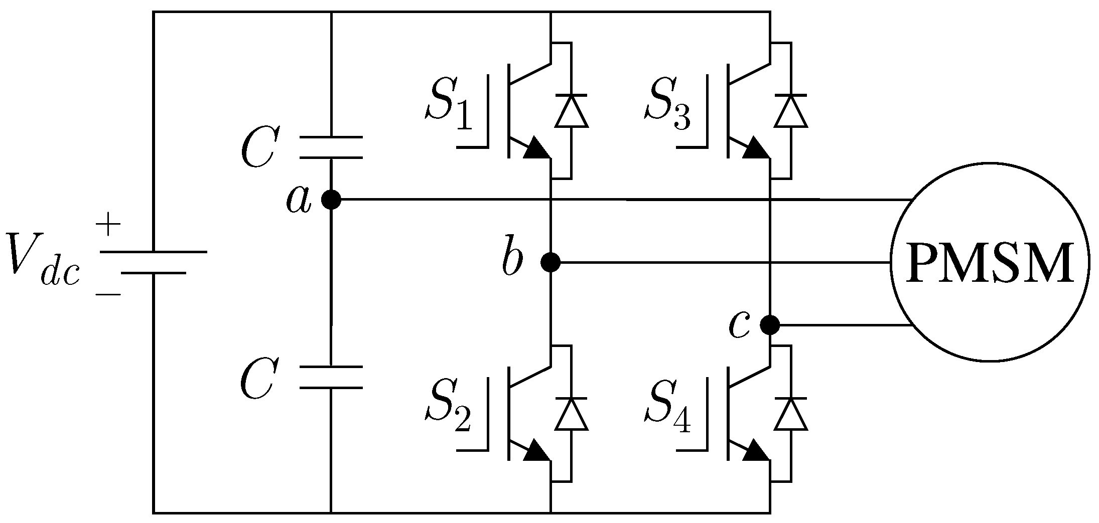
However, the FSTP inverter topology has some drawbacks: since one of the motor phase windings has to be connected to the center-tap of the DC-link capacitors, as shown in Figure 2, current flowing from this leg charges one of the capacitors and discharges the other one, therefore it exposes low frequency harmonic contents. This will cause significantly large fluctuations in the DC-link voltage and create considerably large unbalance three-phase currents at the output [55,56,57]. These unbalanced currents with harmonic components get bigger when the DC-link voltage is lower. Improved controller design is required to balance the capacitor voltages. Moreover, to eliminate the third-order harmonics, a larger value of switching frequency should be selected [58,59,60,61,62,63]. FSTP inverter control topologies have been adapted to sensorless PMSM drives in [26,27,28]. In [66], although the sensorless FSTP inverter of PMSM drive is proposed, ANN is used to achieve a sensorless drive which has a complicated algorithm.
The main contribution of this paper is to modify the -axes stator feedforward voltage control (FFVC) algorithms to achieve a simple, effective and low-cost position sensorless speed control scheme for PMSM drive using FSTP inverters. Normally, the stator feedforward voltages are used to improve the dynamic performance of the FOC of AC drives; however, in this work, they are not only used to improve the dynamic capability of the drive scheme but also are utilized to achieve a simple and effective sensorless control of the FSTP based PMSM drive in which starting under no-load is possible without any open-loop start-up procedures. The earlier work that has been developed for induction motors, and permanent magnet synchronous motors which are driven by SSTP inverter in [66,67,68], respectively are extended for FSTP inverter based sensorless PMSM drives to achieve simple, stable and cost-effective approach under multi-parameter detuning. In [66], flux vector (FV) control is presented for induction motor (IM) as a position sensorless method where the performance is better than V/Hz control but slightly less than indirect field-oriented control (IFOC) [69]. Analysis of the effects of stator resistance variation on the performance of FV and field-oriented (FO) controllers of IM have been proposed in [69] where a back-EMF (back electromagnetic force) detector is developed to reduce the adverse effect of stator resistance on both IFOC, FV and V/Hz control of IM drive with or without position sensors. The performance of the position sensorless FV control of IM in [66] is attempted to be improved in [69] where stator resistance is adjusted based on the error between the reference d-axis current and its feedback component. It is indicated in [69] that the proposed method is best suited for low frequency operation.
The remaining part of this paper is organized as follows. The principles of the proposed position sensorless speed control technique is presented in Section 2. In Section 3, experimental results of the proposed FSTP based position sensorless PMSM drive scheme including no-load start-up, steady-state load disturbance, transient speed change under load, and effect of the parameter variations at medium and low speed regions are presented and discussed. Finally, the conclusion is provided in Section 4.
2. Proposed Position Sensorless Speed Control of Four-Switch Three-Phase PMSM Drive Based on Stator Feedforward Voltage Control
2.1. Steady-State and Dynamic Mathematical Models of PMSM
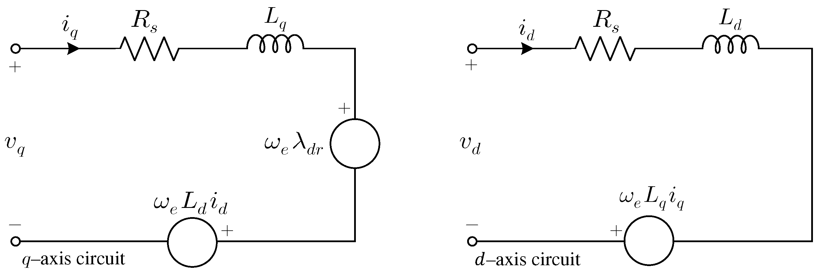
The -axes dynamic model shown in Figure 3 is used to evaluate the field-oriented control (FOC) of PMSM. The rotating frame based stator voltage equations and stator flux linkages neglecting the effects of magnetic saturation and magnetic hysteresis are given by
where , , , are the stator voltages and currents in frame, respectively; is the stator resistance; and represent the –axes inductances; denotes the rotor angular electrical speed; and are the -axes stator flux linkages in which and are the frame rotor flux linkages where is the permanent magnet flux linkage and [70,71,72]. For surface-mounted permanent magnet synchronous motor, where is the stator inductance of the surface-mounted PMSM.
2.2. Principles of the Proposed Position Sensorless Scheme
The main purpose of the feedforward voltage control is to transform -axes reference currents into -axes reference voltages which are decoupled with each other. The feedforward de-coupling approach computes stator -axes voltage references directly by using the steady-state model of the motor given by Equations (5) and (6). As mentioned above, the torque producing component and the flux component are obtained by a q-axis current and a d-axis current reference command signals, respectively. The q-axis current reference component is fed into a first-order time-delay element whose output serves as the input to the de-coupling computing unit. In this way, the torque producing current component response is actually established in advance upon which corresponding stator voltage component , which can ensure that the de-coupling of the motor can be calculated based on the inverse derivation of the motor model. The feedforward de-coupling computing equations are represented by Equations (5) and (6). It is apparent that the feedforward de-couple approach does not only depend on the output of the current regulator to adjust the torque output. Even if the current PI regulators are open-loop, the desired performance of the system can still be achieved, thus ensuring the stability of the system. The d-axis current regulator output can be used to promote the dynamic property while decreasing the impact of parameter variations on the performance of the system. It is seen from Equations (5) and (6) that the currents in the -axes can be controlled by the -axes voltages and rotor speed . In a steady state, rotor frequency is equal to the frequency of the stator voltage. Assuming that the actual currents and follow the reference currents and closely in a steady-state, the -axes stator feedforward voltage equations for the proposed position sensorless speed control of PMSM driven by FSTP inverter are expressed as
where is the d-axis current controller output, which is multiplied by K gain and added to the q-axis voltage equation in Equation (7) symbolizing the dynamic term in Equation (8) to minimize the errors in the PI regulator under dynamic changes in parameters and disturbance and is the the q-axis current regulator output. The term in Equation (8) also acts as the dynamic representation in d-axis voltage equation given in Equation (2) to improve the transient response of the sensorless operation. By combining the dynamic stator voltage Equations (1) and (2) and the proposed feedforward stator voltage estimator Equations (7) and (8), K gain is obtained to be proportional to , in which and are the sample difference of the d- and q-axes currents, respectively. Under the dynamic conditions such as load disturbance, reference and parameter changes, a misalignment between the reference frame and the rotor flux vector produces non-zero terms represented by the derivative term in the d-axis voltage which is the output of the d-axis current regulator called . Since the feedforward control of is determined by Equation (8) on the assumption of existing field alignment, such a misalignment causing deviation will generate a correcting signal from the controller. This signal through a K gain affects the q-axis voltage and, therefore, as well, causing the q-axis current regulator to accelerate or decelerate the reference frame to reconstruct the correct field orientation and, therefore the accurate rotor speed is obtained. Since the torque increases when the electrical rotor speed increases, as a result the rotor flux linkage angle can be derived from integration of the q-axis current controller output. Therefore, the estimated electrical rotor speed, related to the torque producing current , is obtained from the output of the q-axis current regulator through a first order low pass filter. The first order low pass filter at the feedback of the speed estimation loop reduces the transient effects that occur from the output of the q-axis current regulator. Although the system is equipped with d- and q-axes current controllers, the internal cross-coupling between the input variables and state variables of the machine is not eliminated under dynamic conditions, therefore the desired decoupled machine structure is not established. The reason is that the electrical rotor position is not determined by the rotor flux linkage vector. It is governed by the q-axis current error instead, which through the q-axis current regulator, accelerates or decelerates the reference frame. A nonzero value of the q-axis rotor flux linkage indicates a misalignment of the field-oriented reference frame. It is now assumed that the shaft speed changes by a sudden increase of the load torque. The subsequent decrease of rotor speed produces a negative . Simultaneously, the q-axis component which is the back-EMF that acts on the stator is increased, therefore the q-axis stator voltage value increases as well. The consequence is that rises, delayed by the first order low pass filter time constant, which restores to its original zero value after the delay. Before this readjustment takes place, has already assumed a permanent nonzero value, and field orientation is lost. A similar effect occurs on a change of which instantaneously affects , while this disturbance is compensated for only after the time delay of the first order low pass filter by the feedforward adjustment of through . Undesired perturbations are eliminated by the addition of the first order low-pass filter. Maintaining field orientation still needs further improvement. The signal in Equation (1) contributes to back-EMF which influences the stator current derivative. A misalignment between the reference frame and the rotor flux vector produces a nonzero value, giving rise to a back-EMF component that changes . Since the feedforward control of is determined by Equation (8) on the assumption of existing field alignment, such a deviation will invoke a correcting signal from the controller. This signal is used to influence, through a gain constant K, upon the quadrature voltage and hence on as well, causing the controller to accelerate or decelerate the reference frame to reestablish accurate field alignment.
At steady-state, the output of the d-axis current controller and rotor flux linkage relationships are expressed in per-unit form when using Equation (1) as
where is constant in a steady-state, hence the rotor flux linkage is proportional to as
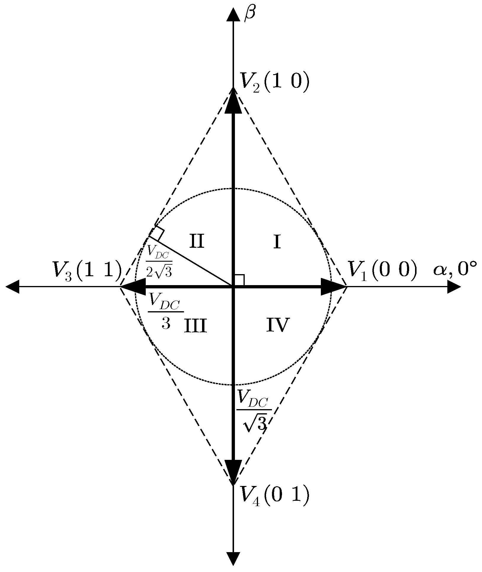
As opposed to the classical six-switch three-phase (SSTP) inverter, where six non-zero and two-zero voltage vectors exist, only four active non-zero voltage space vectors and no zero voltage vectors are available in FSTP inverters, as shown in Figure 4 where phase-a is connected to the centre-tap, as illustrated in Figure 2. Compared to the six-switch counterpart, since each vector is aligned to an axis, vector representations are simple in FSTP inverter topology enabling more easier space vector pulse width modulation (SVPWM) strategy. Maximum line to neutral voltage is and can be used to normalize the space vectors and . In the structure of the SVPWM switching method for the proposed FSTP inverter based sensorless scheme, the reference voltage vector in each sector can be represented with the two closest voltage space vectors and zero voltage vectors in plane. For example, when the reference voltage resides in Sector I, two non-zero voltage vectors are and , and the zero voltage vector is obtained as the combination of the smallest vectors, and , in the timing diagram of the switching sequence. The time duration of and when the reference voltage vector is located in Sector I are obtained as
where T is the switching period, and is the estimated rotor electrical position. The time durations that are used in the SVPWM scheme of the proposed FSTP inverter based sensorless scheme for phase-b, phase-c, and zero vectors are also calculated using Equations (11) and (12), respectively, as follows:
The timing calculations can be obtained in a similar fashion for the rest of the sectors as well for the proposed sensorless control strategy. As can be seen in the time duration calculations, K gain has an influence on defining the duty cycle values of the switching actions in the proposed scheme. Since only two duty cycle values and given in Equation (13) are required in the proposed FSTP inverter based sensorless scheme, SVPWM complexity is minimized as opposed to the six-switch counterpart. Moreover, with less duty cycle components, dead-time compensation strategies can be simply implemented using the proposed sensorless scheme in the FSTP inverter compared to the SSTP inverter.
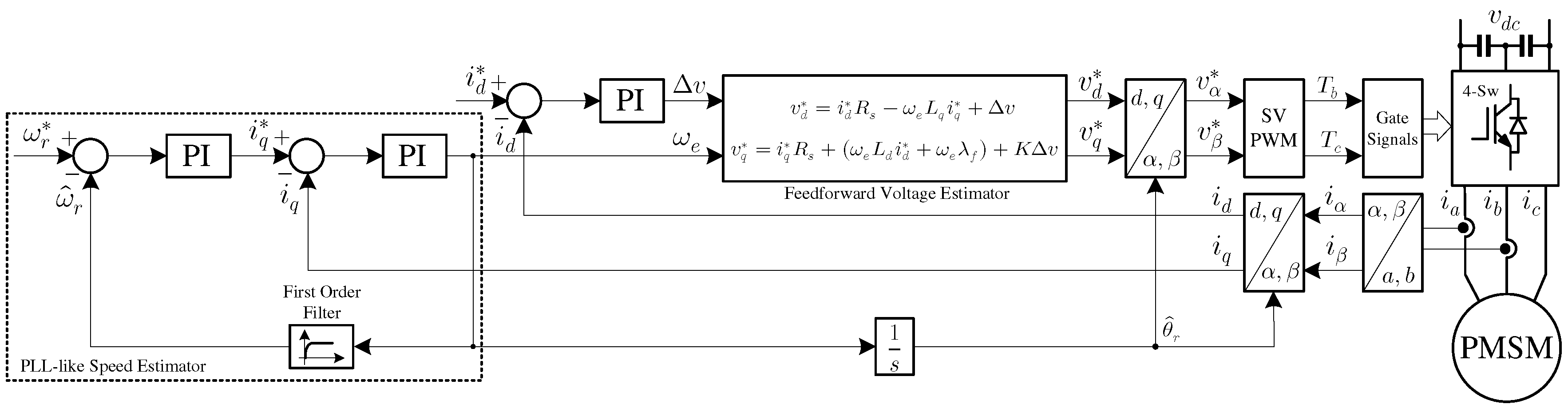
The overall stability of the proposed position sensorless speed control of PMSM scheme driven by an FSTP inverter under multiple simultaneous parameter variations ( and ) is improved by proper selection of K gain in Equation (7). The output of the q-axis current controller, which is the electrical angular estimated speed , depends on the K gain that enables the system to respond dynamically and provides the system to protect its stability especially at low speeds [73]. The feedforward used in this work is actually the voltage estimator. The K gain is the gain matrix which stabilizes the estimator. An appropriate K gain must be selected to achieve a stable loop. Therefore, irrespective of other parameters, K gain is tuned to be five for this motor. The selected value of the K gain changes for various different motors. The low selected K gain value is effective while parameters do not change; however, under high parameter variations, high K gain value provides stable operation. At start-up, the K gain value is selected to be one not having an oscillation and, when the motor reaches the steady-state after ramping, its value is changed from one to five in a ramp during a specified time; therefore, the overall system is not affected from parameter variations. The proper maximum K gain that stabilizes the system under multi parameter detuning can be varied for other motors as seen in various observers. The selection criteria of K gain under heavy multiple parameter detuning in Equation (7) are investigated through experiments in Section 3. A complete block diagram for the proposed position sensorless PMSM drive scheme based-on stator feedforward voltage control (FFVC) using a four-switch space vector PWM (SVPWM) three-phase VSI is illustrated in Figure 5. The electrical angular speed which is the output of the q-axis current controller is passed through a low-pass filter to obtain the estimated rotor speed in a similar fashion as the phase-lock loop (PLL), as shown in Figure 5.
2.3. Problem Formulation of the Proposed Method
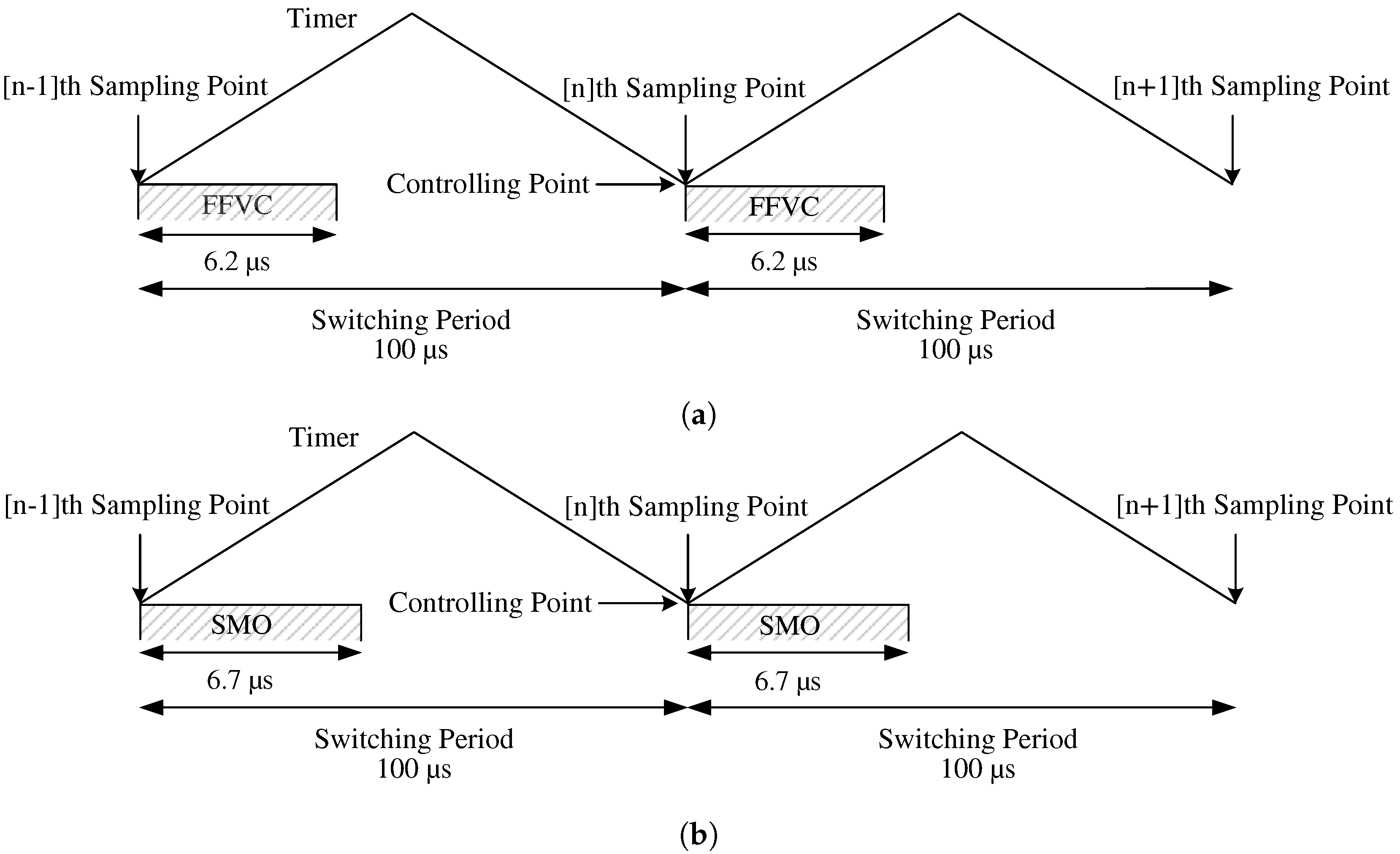
The novelty of the proposed position sensorless speed control technique lies with the fact that it is the first contribution to the literature regarding the stator feedforward voltage control (FFVC) based position sensorless control of a PMSM drive that is insensitive to multi-parameter variations using a four-switch three-phase inverter under full load conditions at a low to nominal speed range. The stator feedforward voltage control (FFVC) algorithm for a four-switch three phase (FSTP) inverter based PMSM is developed for an effective sensorless drive scheme. To develop the stator feedforward voltage control (FFVC) algorithm, the term , the d-axis current controller output, is used in the steady-state q-axis stator feedforward voltage equation is multiplied by a K gain and added to the q-axis steady-state stator feedforward voltage equation such that the term represents the dynamic behavior in the q-axis voltage equation. Therefore, the term holds the function of minimizing the errors in the PI regulator under dynamic changes in parameters and disturbance. Similarly, the term also acts as the derivative representation in a steady-state d-axis voltage equation for achieving a better transient response in the sensorless operation. Moreover, even though the proposed FFVC method is a closed-loop sensorless FOC, it is similar to control that is commonly used for induction motors; therefore, starting PMSM from zero speed is feasible. This was not practically possible before with the sensorless schemes that relied on the estimation of back-EMF such as classical Sliding Mode Observer (SMO) based position sensorless techniques. To show the superiority of the proposed method, it is compared with the classical back-EMF estimation method called Sliding Mode Observer (SMO). It is shown in the experimental study that the proposed sensorless scheme takes only 0.5 s of processing time compared to the quite fast back-EMF sensing method called SMO. It is also believed that the ANN method given in [64] is difficult to implement and takes much longer processing time compared to our proposed scheme. Advantages and disadvantages of the proposed scheme with the existing well-known sensorless techniques are depicted in Table 1. In this paper, it is demonstrated that the parameter sensitivity is tremendously reduced by properly selecting the highest possible gain of the d-axis current regulator output used in the q-axis stator feedforward voltage control equation and therefore proper operation of the position sensorless FSTP based PMSM drive scheme is feasible even at considerably low to medium speed range.
3. Experimental Verification
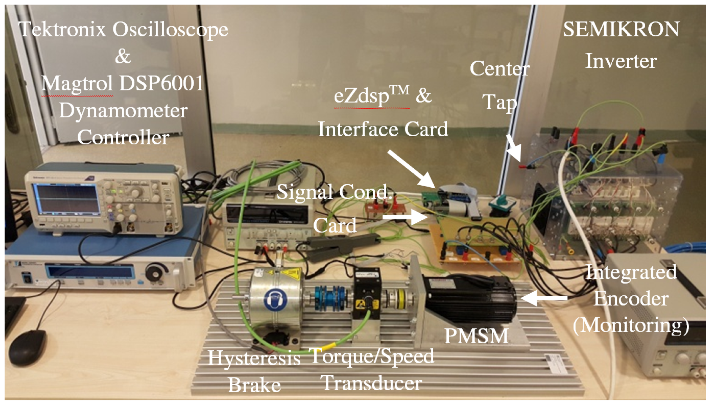
The implementation of the proposed position sensorless control scheme of a four-switch three-phase (FSTP) PMSM drive has been evaluated using an experimental test-bed, shown in Figure 6. The proposed control algorithm is implemented using a floating-point TMS320F28335 DSP with 10 kHz switching frequency.
3.1. Experimental Set-up
The experimental set-up consists of a hysteresis dynamometer set, an inverter, a PMSM with an optical incremental encoder integrated for monitoring purpose, an eZdsp® board (Spectrum Digital, Stafford, TX, USA) with a TMS320F28335 DSP chip, and an interface and signal conditioning cards. The voltage unbalancing is seriously increased when the capacitors are selected as small. The inverter generates a maximum 4.3 s dead-time and has two 2200 F caps. The value of the DC-link voltage is selected to be 565 V, which is the nominal PMSM DC-link voltage. Normally, the optimal value of DC bus voltage should be higher than 565 V in four-switch inverters to compensate for the reduction in power compared to a six-switch inverter case. The specifications and parameters of the PMSM are illustrated in Table A1 in the Appendix A.
3.2. Experimental Results
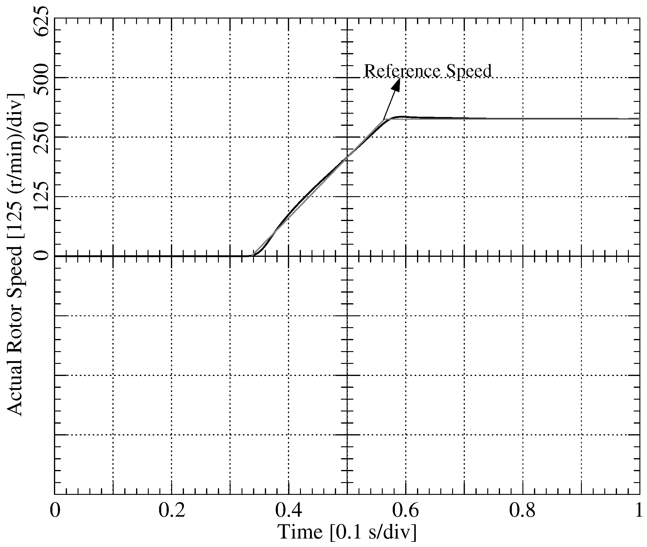
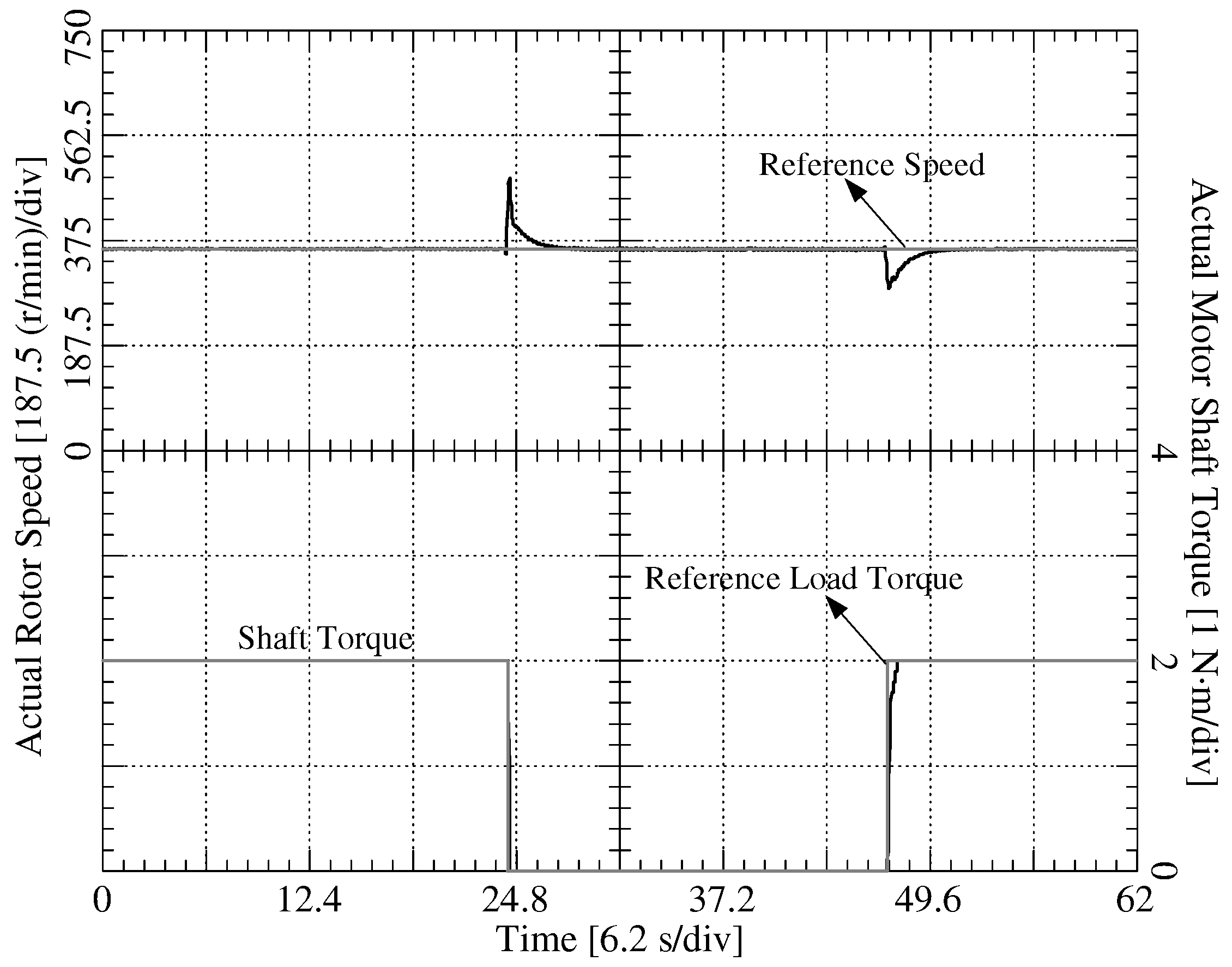
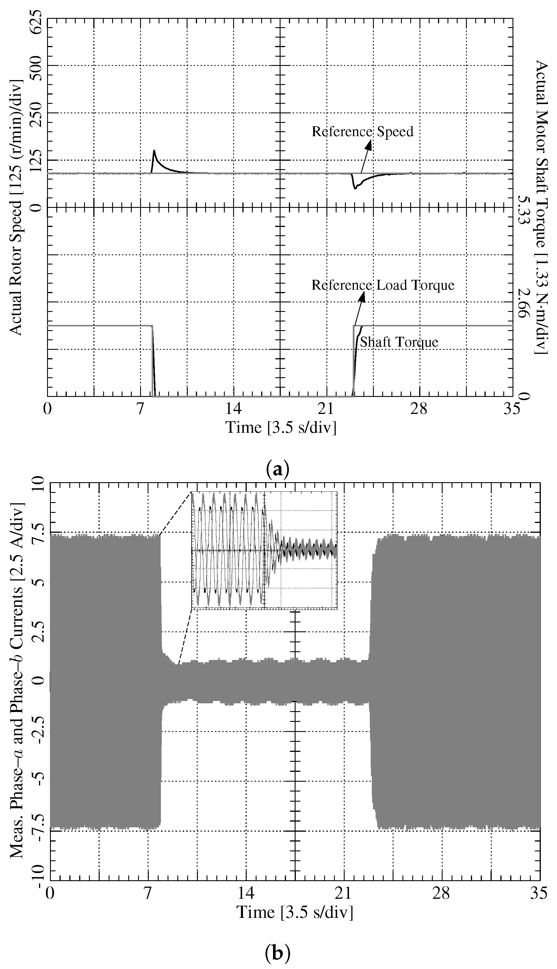
In the experiments, digital proportional-integral (PI) controllers are used in the speed and current loops. The initial rotor position is set to a predetermined value for proper start-up. Since the proposed position sensorless algorithm relies on the back-EMF based method, it is not possible to start at full load. Therefore, the motor is ramped from 0 to 360 r/min in 2 s under no-load. No instability is observed in the experimental no-load start-up using the proposed position sensorless scheme, as shown in Figure 7. Due to low sampling rate of the Magtrol dynamometer data acquisition system (Buffalo, NY, USA), in all experiments, the rotor speed and load torque data are obtained by the high resolution DAC module. During the steady-state speed of 360 r/min, a nominal step load torque (2 N·m) injection and rejection are applied, respectively. The resultant speed and shaft torque are provided in Figure 8. The satisfactory transient speed response is achieved under full load injection, and rejection with a reasonable low frequency oscillation without parameter detuning with K gain is chosen as 1.
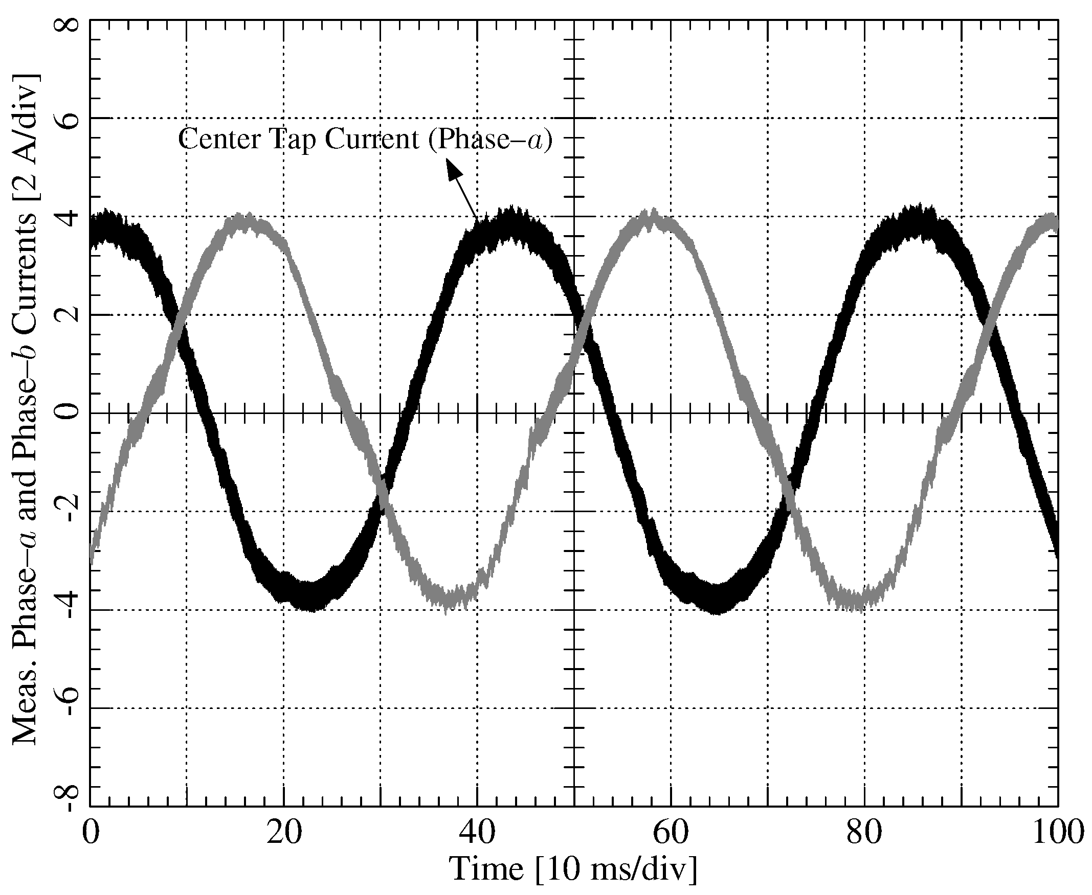
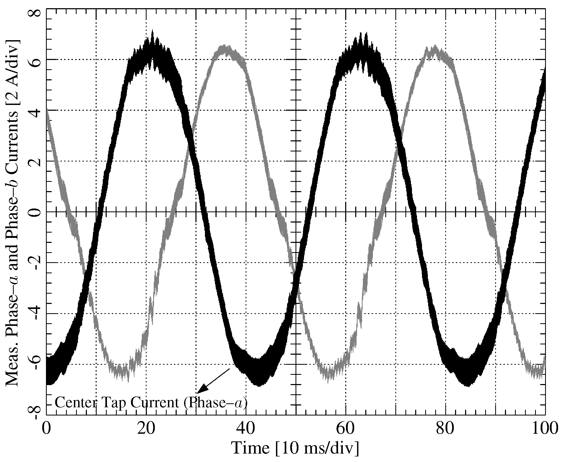
In Figure 9, the experimental steady-state phase-a and –b current waveforms are presented at 360 r/min under full load without parameter detuning when . As can be seen in Figure 7, Figure 8 and Figure 9, the proposed position sensorless method is able to drive the PM motor without any instability under full load injection and rejection assuming that there are no parameter variations in the PM motor when the K gain is chosen as 1. Due to slight misalignment and concentrated windings of the motor, phase currents show some harmonic signatures, as seen in Figure 9. Moreover, since the dead-time effect is not mitigated, the phase current waveform shows some additional distortion in particular at zero crossings and during positive and negative peaks. The effects of stator resistance and rotor flux linkage variations on the overall performance of the proposed drive are also investigated. The machine is run with external resistance under heavy load for a certain time until the PM rotor flux-linkage amplitude decreases 40% less than its original value. Because changing directly in the actual machine is a difficult task, the motor is heated up with external resistance under heavy load first to achieve 82.35% higher and 40% less ; then, the back-EMF constant and the final are measured afterwards. The resultant phase-a and -b axes current waveforms are shown in Figure 10 when both and PM rotor flux linkage values are detuned under full load (2 N·m). Although 90% higher currents are drawn by the motor as shown in Figure 10, which results in more losses than normal operation, the proposed position sensorless method is able to drive the PM motor even under multiple simultaneous high parameter variations without any stability problem.
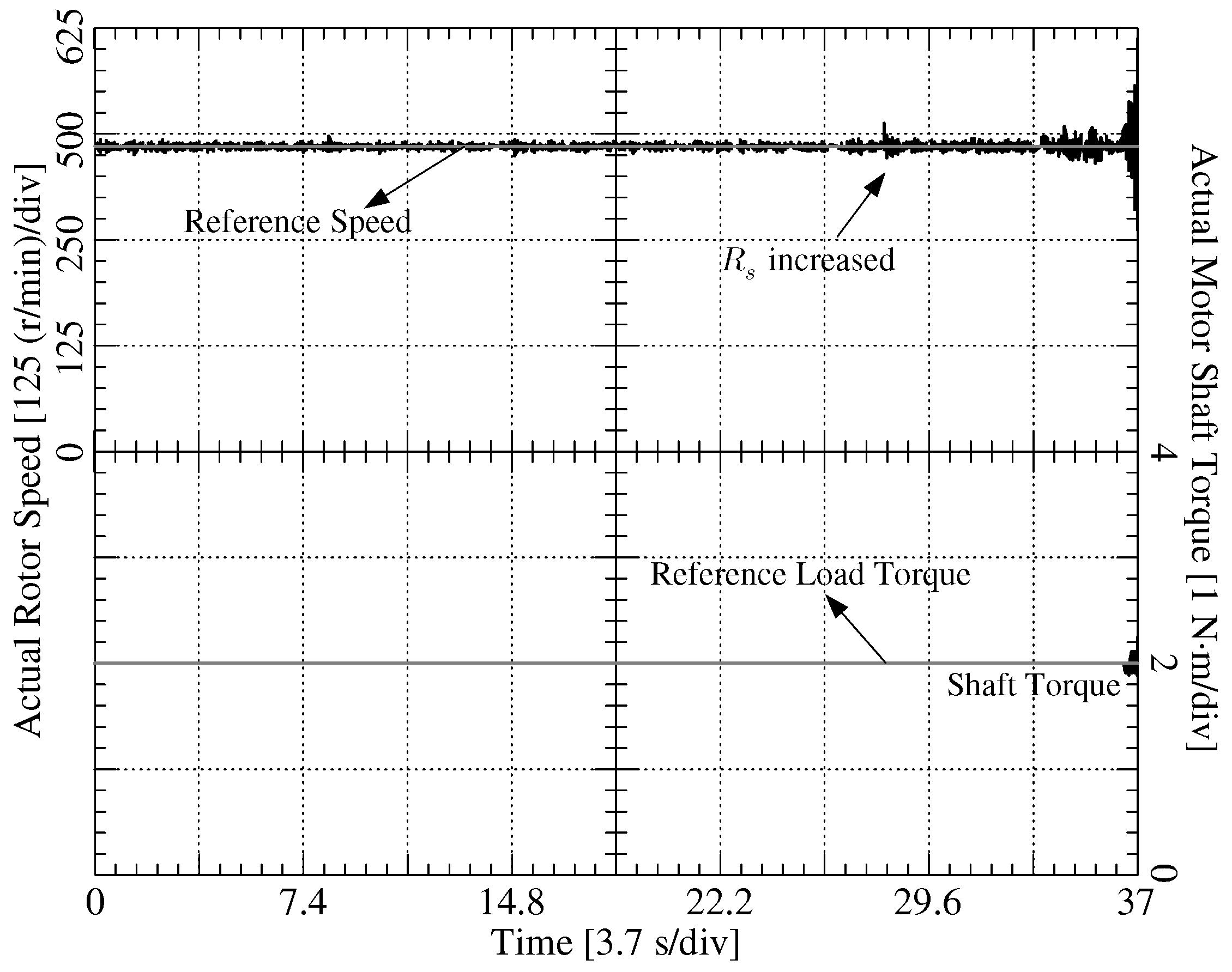
If the PM rotor flux linkage is estimated using observer like methods without estimating the remaining parameters ( and ) almost simultaneously, the correct PM rotor flux linkage value cannot be obtained when these remaining parameters vary greatly. It is shown in previous work that is not affected by the variation of PM rotor flux linkage [74,75]. However, it is also previously reported in [73,74] that is highly sensitive to PM rotor flux linkage variations and vice versa. It is observed in the simulations that, when a classical full-order observer is used to estimate the PM rotor flux linkage when is changed 82.35% higher than its nominal value, then the PM rotor flux linkage is estimated to be 68% higher than the actual value in the proposed position sensorless speed control scheme. Even though the correct PM rotor flux linkage estimation can be achieved in the drive scheme when is increased 82.35% higher than its actual value and is decreased 40% lower than its original value at the same time, the peak motor phase current increases 90% more than the expected full loaded value under multiple parameter variations. Although observing the changed values correctly allows stable position sensorless speed control, it does not improve machine efficiency because the machine inherently draws more current when the parameters are highly detuned. Figure 11 illustrates the effect of sudden increase under low K gain of 1 at s. It is seen that when a step increase in is applied under full load at 360 r/min, instability in speed is observed, which is shown in Figure 11. The rotor speed oscillates around the reference speed after the switch is closed and, a few seconds later, the motor stalls. The performance of transient speed response at no-load startup and during steady-state load injection and rejection can be improved by carefully selecting K gain and time constants in the speed PI regulator and speed estimator filter. The importance of K gain in Equation (7) is observed in the low and medium speed range. When K is selected as low, between 1 to 3, the low to medium speed position sensorless method fails under heavy parameter detuning; however, if it is high enough, between 4 to 7, stability of the position sensorless speed control scheme is maintained even under heavy multiple simultaneous parameter detuning in the low to medium speed range. The value of K under parameter variation depends on the size of the PM motor, speed, DC-link value, amount of the parameter variations, nonlinearities of the overall system, etc.
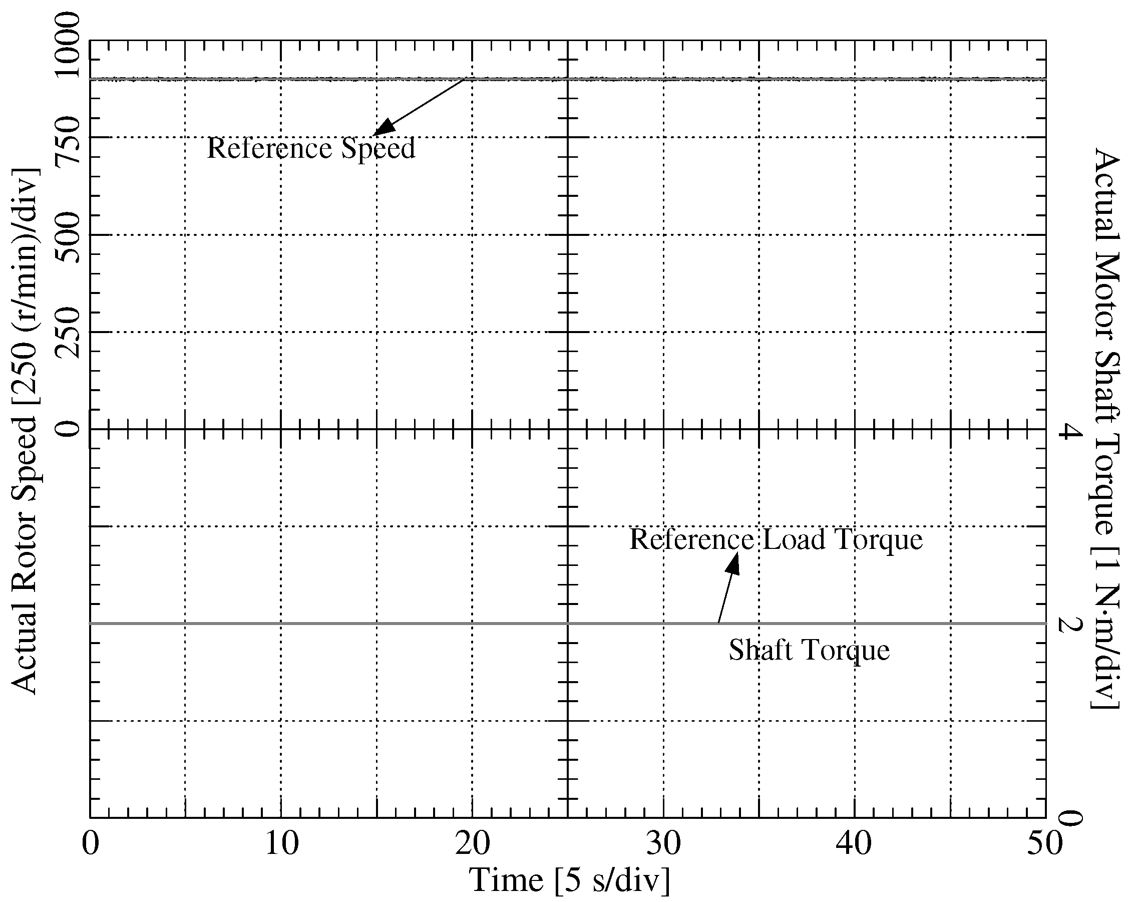
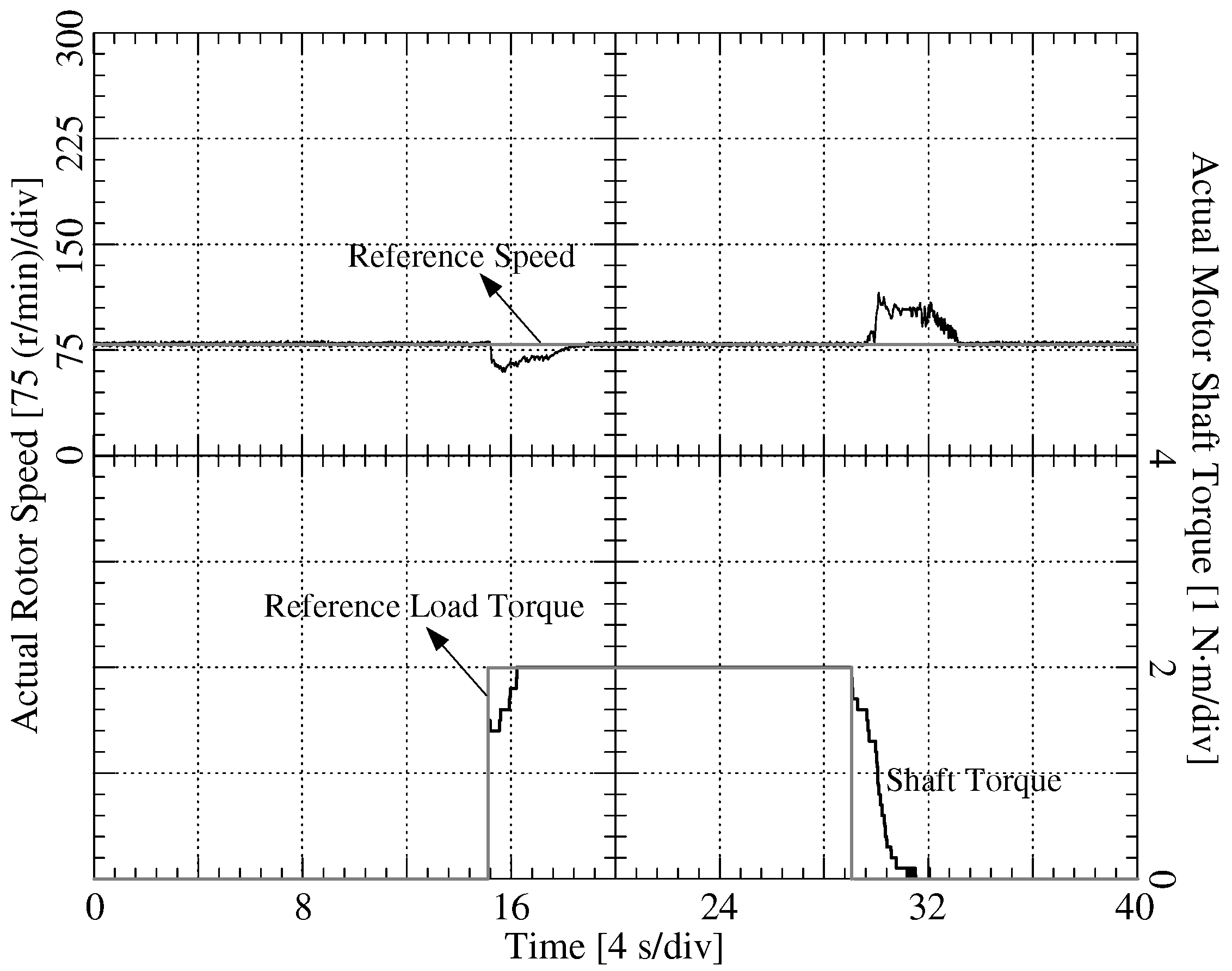
The nominal speed (900 r/min) full load steady-state experimental test while is increased by 82.35% and is decreased by 40% with (high) given in Figure 12 shows a non-oscillatory stable speed response. Moreover, an experimental low speed steady-state (90 r/min) speed response is shown in Figure 13a where full load (2 N·m) rejection is performed at s and full load injection is applied at s, while is increased by 82.35% and 40% less rotor flux linkage compared to the actual value with (high). This is the lowest stable speed under full load injection and rejection with heavy parameter detuning.
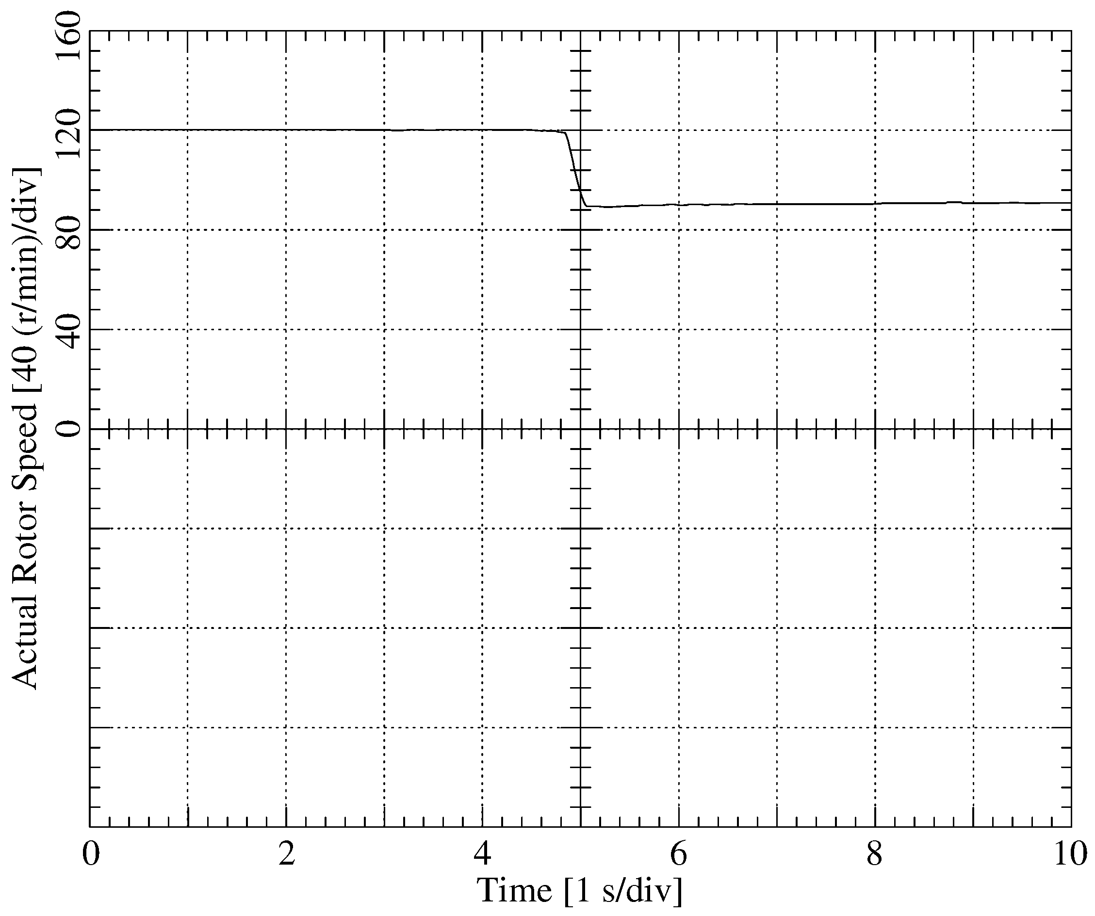
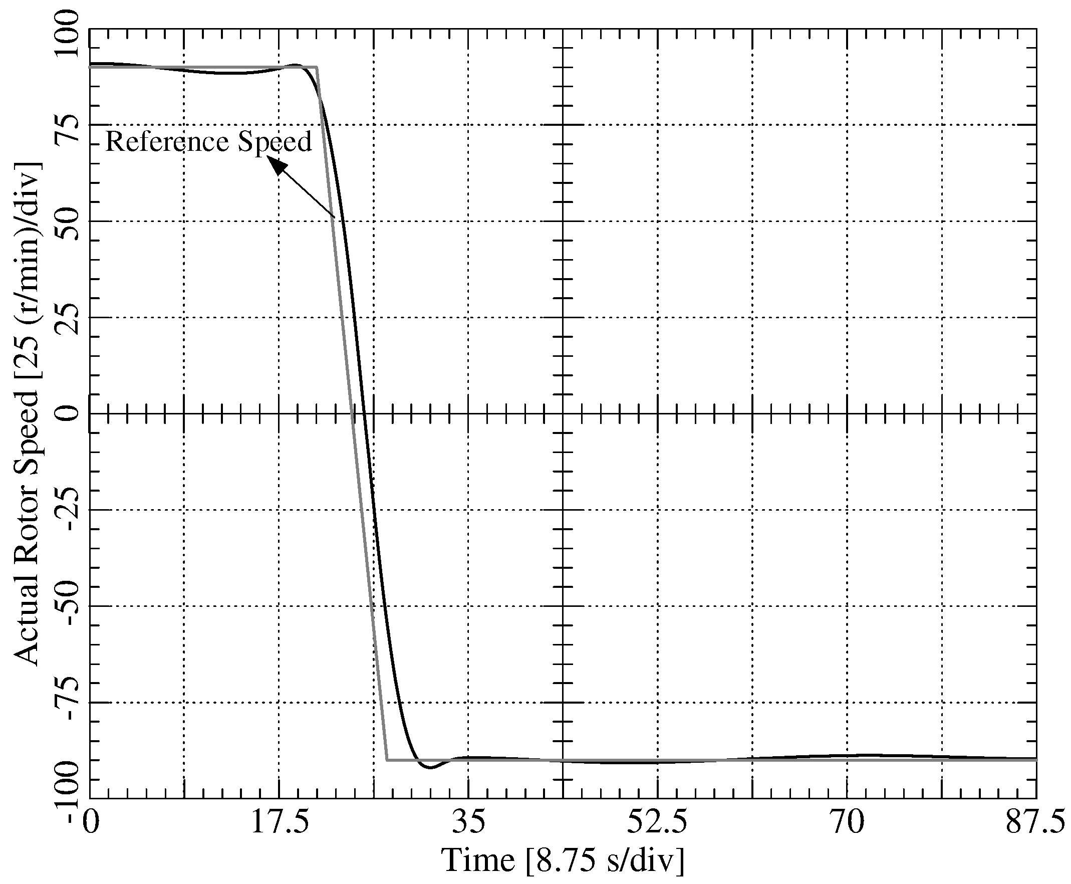
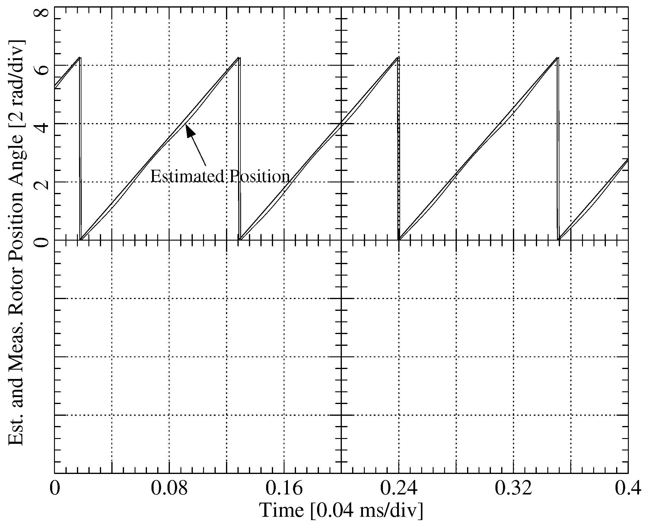
Figure 13b shows phase-a and -b current waveforms during steady-state under full load and at no-load, load rejection and when load injection has occurred, respectively. The stability is retained with reasonably low frequency oscillations. The speed transient step-down test from 120 r/min to 90 r/min under rated load is achieved successfully with high parameter detuning without instability using the proposed scheme, as shown in Figure 14. The least possible speed under no-load without parameter detuning is achieved to be around 78 r/min with the proposed scheme, as shown in Figure 15 where full load injection and rejection tests have been performed at s and s, respectively. In Figure 16, the speed is ramp down from +90 r/min to −90 r/min in 8 seconds under heavy multi-parameter changes without instability. The speed response given in Figure 16 has a good transient behavior and exhibits small fluctuations in a steady-state. An experiment with the actual position and the estimated position in the steady-state under a nominal load at the lowest possible velocity is given in Figure 17 under heavy multi-parameter changes. It is seen in Figure 17 that the estimated position tracks the actual position quite well at 90 r/min under heavy multi-parameter detuning without instability.
In brief, an appropriate K gain which is shown in Table A2 in Appendix A must be selected to achieve a stable loop. Therefore, irrespective of other parameters, K gain is tuned to be five for this motor. The selected value of the K gain changes for various different motors. The low selected K gain value is effective while parameters do not change much; however, under heavy parameter variations, high K gain value provides stable operation. In experimental studies, at start-up, the K gain value is selected to be one that does not have an oscillation and, when the motor reaches the steady state after ramping, its value is changed from one to five in a ramp during a specified time; therefore, the overall system is not affected from parameter variations. The proper maximum K gain that stabilizes the system under multi parameter detuning can be different for other motors as seen in various observers.
Since there is a no zero-voltage vector as in SSTPI, there exist more harmonics as well as oscillations in currents and voltages in FSTPI. Under insufficient DC bus voltage conditions, the targeted power level cannot be reached due to the ratio of the voltages between SSTPI and FSTPI, which is 1/3 to 2/3 and the low speed operation of FSTPI with the proposed method fails. Moreover, even if the DC bus voltage is increased, serious voltage and current oscillations and harmonics in the system are observed and the motor insulations might break. Normally, DC voltage in FSTP inverter should be at ideal conditions; however, in the real system, it becomes ≠ during steady-state operation. Therefore, based on the measurement time, differences are observed between peak values of phase-a and –b currents. Moreover, because the dead-time effect is not compensated, the phase current waveform exhibits some additional distortion especially at zero crossings and at around positive and negative peaks. When the applied frequency is 6 Hz (0.1 per-unit), the magnitude of the voltage fluctuation is obtained as 34.10 V with two 2200 F DC-link capacitors. For example, if the fluctuation voltage is desired to be 15 V at 0.1 per-unit speed, the rated capacitance value has to be selected as 5000 F.
3.3. Comparison of the Proposed Method with Classical SMO
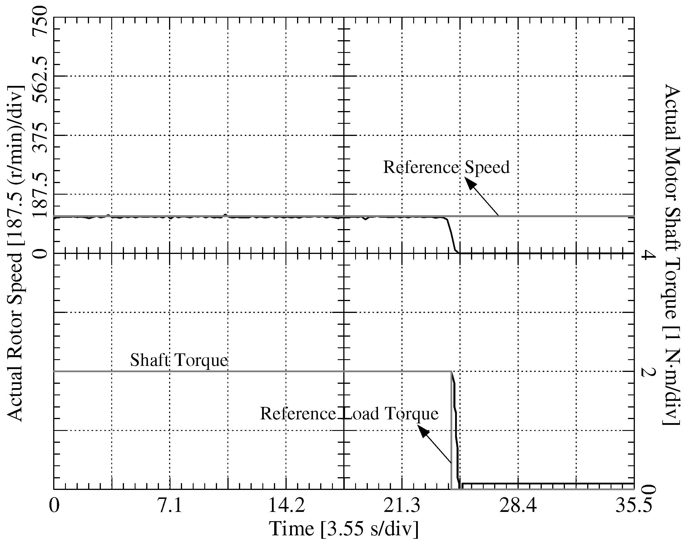
The proposed control scheme is compared with the well-known position sensorless control method called sliding-mode observer (SMO). Sliding mode observer (SMO) is a promising approach for position sensorless schemes because of its independence from system parameter variations, less sensitivity to external disturbance and interference, fast convergence and robustness [76,77,78,79]. The experimental results demonstrate that, as opposed to the classical sliding-mode control (SMO), the proposed position sensorless method is stable at low speed ranges under full load compared to classical SMO even under heavy parameter detuning. The rotor speed is attempted to be decreased more down to 90 r/min at s during approx. 80% higher stator resistance than the actual value and 40% less rotor flux linkage compared to the original rotor flux as in the proposed scheme; however, SMO is not able to track the reference speed and the rotor speed eventually goes to zero, as seen in Figure 18. The implementation process time related to the proposed method and the classical position sensorless method i.e., SMOs are compared in Figure 19. It is shown that the proposed method consumes 0.5 s less time compared to the classical back-EMF sensing method (SMO). In this paper, it is demonstrated that the parameter sensitivity is tremendously reduced by properly selecting the highest possible gain of the d-axis current regulator output used in the q-axis stator feedforward voltage control equation and therefore proper operation of the position sensorless FSTP based PMSM drive scheme is possible even at considerably low to medium speed range.
4. Conclusions
In this paper, a position sensorless speed control method based on stator feedforward -axes voltage control (FFVC) has been proposed for low-cost four-switched three-phase (FSTP) PMSM drive. Compared to traditional sensorless methods, the proposed method is simpler, more effective, and leads to a lower implementation processing time. Moreover, with the proposed method, the FSTP driven PMSM can start-up from zero speed under no-load without requiring any additional open-loop start-up procedures.
It is shown in the experiments that selecting a possible high K gain in the stator FFVC algorithm enhances the stability of the overall drive even under heavy multiple simultaneous parameter variations, making the overall position sensorless speed control scheme quite insensitive to multiple parameter variations.
Author Contributions
O.C.K. developed software and wrote the original draft preparation. S.B.O. conceived of the idea of the research, participated in all study phases, and provided guidance and supervision. All authors have contributed significantly to this work.
Funding
This work was supported by the Scientific and Technological Research Council of Turkey (TUBITAK) funded project (112E263).
Conflicts of Interest
The authors declare no conflict of interest.
Appendix A

Table A1.
Specifications and parameters of the Permanent Magnet Synchronous Motor (PMSM).
| Parameter | Value |
|---|---|
| Number of poles | 8 |
| Line-to-neutral rms voltage (V) at 200 Hz | 230 |
| Rated torque (N·m) | 2 |
| Rated speed (r/min) at 60 Hz (1 per-unit) | 900 |
| Rated rms current (A) | 4 |
| Stator inductance (H) | 0.0033 |
| Stator resistance () | 3.4 |
| Rotor magnetic flux linkage (Wb) | 0.095 |
| Moment of inertia (kg.m2) | 0.0075 |
Table A2.
K gain selection criteria.
| K Value | Max. Variation | Speed Oscillation at Max. |
|---|---|---|
| 1 | 4% | 20% |
| 2 | 14% | 17% |
| 3 | 27% | 12% |
| 4 | 58% | 7% |
| 5 | 80% | 1% |
| 6 | 54% | 12% |
| 7 | 38% | 15% |
References
- Ma, Z.; Zhang, X. FPGA Implementation of Sensorless Sliding Mode Observer With a Novel Rotation Direction Detection for PMSM Drives. IEEE Access 2018, 6, 55528–55536. [Google Scholar] [CrossRef]
- Rind, S.J.; Jamil, M.; Amjad, A. Electric motors and speed sensorless control for electric and hybrid electric vehicles: A review. In Proceedings of the 53rd International Universities Power Engineering Conference (UPEC), Glasgow, UK, 4–7 September 2018. [Google Scholar]
- Xu, D.; Wang, G.; Zhang, G.; Yu, Y. A review of sensorless control methods for AC motor drives. CES Trans. Elect. Mach. Syst. 2018, 2, 104–115. [Google Scholar] [CrossRef]
- Singh, S.; Tiwari, A.N. Various techniques of sensorless speed control of PMSM: A review. In Proceedings of the 2017 Second International Conference on Electrical, Computer and Communication Technologies (ICECCT), Coimbatore, India, 22–24 February 2017. [Google Scholar]
- Zhang, G.; Wang, G.; Xu, D. Saliency-based position sensorless control methods for PMSM drives—A review. Chin. J. Electr. Eng. 2018, 3, 14–23. [Google Scholar] [CrossRef]
- Rind, S.; Ren, Y.; Jiang, L. Traction motors and speed estimation techniques for sensorless control of electric vehicles: A review. In Proceedings of the 49th International Universities Power Engineering Conference (UPEC), Cluj-Napoca, Romania, 2–5 September 2014. [Google Scholar]
- Benjak, O.; Gerling, D. Review of position estimation methods for PMSM drives without a position sensor, part III: Methods based on saliency and signal injection. In Proceedings of the International Conference on Electrical Machines and Systems, Incheon, Korea, 10–13 October 2010. [Google Scholar]
- Wang, G.; Yang, B.; Zhang, G.; Zhang, X.; Xu, D. Comparative investigation of pseudorandom high-frequency signal injection schemes for sensorless IPMSM drives. IEEE Trans. Power Electron. 2017, 32, 2123–2132. [Google Scholar] [CrossRef]
- Wang, G.; Yang, B.; Yuan, B.; Wang, B.; Zhang, G.; Xu, D. Pseudo-random high-frequency square-wave voltage injection based sensorless control of IPMSM drives for audible noise reduction. IEEE Trans. Ind. Electron. 2016, 63, 7423–7433. [Google Scholar] [CrossRef]
- Zhang, G.; Wang, G.; Xu, D.; Zhao, N. ADALINE-network-based PLL for position sensorless interior permanent magnet synchronous motor drives. IEEE Trans. Power Electron. 2016, 31, 1450–1460. [Google Scholar] [CrossRef]
- Wang, Y.; Xu, Y.; Zou, J. Sliding mode sensorless control of PMSM with inverter nonlinearity compensation. IEEE Trans. Power Electron. 2019, 1450–1460. [Google Scholar] [CrossRef]
- Wang, M.S.; Tsai, T.M. Network control of sensorless PMSM controlled system for power consumption and performance improvement. Energies 2017, 10, 1780. [Google Scholar] [CrossRef]
- Bao, D.; Pan, Y.; Wang, X.; Li, K. Adaptive synchronous-frequency tracking-mode observer for the sensorless control of a surface PMSM. IEEE Trans. Ind. Electron. 2018, 54, 6460–6471. [Google Scholar] [CrossRef]
- Xu, W.; Jiang, Y.; Mu, C.; Blaabjerg, F. Improved nonlinear flux observer-based second-order SOIFO for PMSM sensorless control. IEEE Trans. Power Electron. 2019, 34, 565–579. [Google Scholar] [CrossRef]
- Lee, K.; Park, S.; Jeong, S. A seamless transition control of sensorless PMSM compressor drives for improving efficiency based on a dual-mode operation. IEEE Trans. Power Electron. 2015, 30, 1446–1456. [Google Scholar] [CrossRef]
- Van Der Broeck, H.W.; Van Wyk, J.D. A comparative investigation of a three-phase induction machine drive with a component minimized voltage-fed inverter under different control options. IEEE Trans. Ind. Appl. 1984, IA-20, 309–320. [Google Scholar] [CrossRef]
- Lee, J.H.; Ahn, S.C.; Hyun, D.S. A BLDCM Drive With Trapezoidal Back EMF Using Four-Switch Three Phase Inverter. In Proceedings of the Thirty-Fifth IAS Annual Meeting and World Conference on Industrial Applications of Electrical Energy, Rome, Italy, 8–12 October 2000. [Google Scholar]
- Lee, J.H.; Kim, T.S.; Hyun, D.S. A Study for Improved of Speed Response Characteristic in Four-Switch Three-Phase BLDC Motor. In Proceedings of the 30th Annual Conference of IEEE Industrial Electronics Society, Busan, Korea, 2–6 November 2004. [Google Scholar]
- Uddin, M.N.; Radwan, T.S.; Rahman, M.A. Performance Analysis of a 4-Switch, 3-Phase Inverter Based Sost Effective IPM Motor Drives. In Proceedings of the Canadian Conference on Electrical and Computer Engineering, Niagara Falls, ON, Canada, 2–5 May 2004. [Google Scholar]
- Lee, B.K.; Kim, T.H.; Ehsani, M. On the feasibility of four-switch three-phase BLDC motor drives for low cost commercial applications: Topology and control. IEEE Trans. Power Electron. 2003, 18, 164–172. [Google Scholar] [CrossRef]
- Lin, C.T.; Hung, C.W.; Liu, C.W. Position sensorless control for four-switch three phase brushless DC motor drives. IEEE Trans. Power Electron. 2008, 23, 438–444. [Google Scholar] [CrossRef]
- Niasar, A.H.; Vahedi, A.; Moghbelli, H. A novel position sensorless control of a four-switch, brushless dc motor drive without phase shifter. IEEE Trans. Power Electron. 2008, 23, 3079–3087. [Google Scholar] [CrossRef]
- Hung, C.W.; Su, J.T.; Liu, C.W.; Lin, C.T.; Chen, J.H. Fuzzy Gain Scheduling PI Controller for a Sensorless Four Switch Three Phase BLDC Motor. In Proceedings of the Twenty-Fifth Annual IEEE Applied Power Electronics Conference and Exposition, Palm Springs, CA, USA, 21–25 February 2010. [Google Scholar]
- Niasar, A.H.; Moghbeli, H.; Vahedi, A. A Novel Sensorless Control Method for Four-Switch Brushless DC Motor Drive without Using Any 30º Phase Shifter. In Proceedings of the International Conference on Electrical Machines and Systems, Seoul, Korea, 8–11 October 2007. [Google Scholar]
- Ebadpour, M.; Sharifian, M.B.B.; Feyzi, M.R. A Simple Position Sensorless Control Strategy for Four-Switch Three-Phase Brushless DC Motor Drives Using Single Current Sensor. In Proceedings of the 2nd Power Electronics, Drive Systems and Technologies Conference, Tehran, Iran, 16–17 February 2011. [Google Scholar]
- Lin, C.K.; Fu, L.C.; Liu, T.H.; Hsiao, C.F. A Sensorless Position Control for Four-Switch Three-Phase Inverter-Fed Interior Permanent Magnet Synchronous Motor Drive Systems. In Proceedings of the IEEE/ASME International Conference on Advanced Intelligent Mechatronics, Kachsiung, Taiwan, 11–14 July 2012. [Google Scholar]
- Jang, J.S.; Park, B.G.; Kim, T.S.; Lee, D.M.; Hyun, D.S. Sensorless Control of Four-Switch Three-Phase PMSM Drive Using Extended Kalman Filter. In Proceedings of the 34th Annual Conference of IEEE Industrial Electronics, Orlando, FL, USA, 10–13 November 2008. [Google Scholar]
- Fernandes, E.M.; Oliveira, A.C.; Vitorino, M.A.; Dos Santos, E.C.; Santos, W.R.N. Speed Sensorless PMSM Motor Drive System Based on Four Switch Three-Phase Converter. In Proceedings of the 40th Annual Conference of the IEEE Industrial Electronics Society, Dallas, TX, USA, 29 October–1 November 2014. [Google Scholar]
- Ozturk, S.B.; Alexander, W.C.; Toliyat, H.A. Direct torque control of four-switch brushless DC motor with non-sinusoidal back EMF. IEEE Trans. Power Electron. 2010, 25, 263–271. [Google Scholar] [CrossRef]
- Fu, J.R.; Lipo, T. A Strategy to Isolate the Switching Device Fault of a Current Regulated Motor Drive. In Proceedings of the IEEE Industry Applications Conference Twenty-Eighth IAS Annual Meeting, Toronto, ON, Canada, 2–8 October 1993. [Google Scholar]
- Sun, D.; He, Z.; He, Y.; Guan, Y. Four-Switch Inverter Fed PMSM DTC With SVM Approach for Fault Tolerant Operation. In Proceedings of the IEEE International Electric Machines and Drives Conference, Antalya, Turkey, 3–5 May 2007. [Google Scholar]
- Luczak, D.; Siembab, K. Comparison of Fault Tolerant Control Algorithm Using Space Vector Modulation of PMSM Drive. In Proceedings of the 16th International Conference on Mechatronics, Brno, Czech Republic, 3–5 December 2014. [Google Scholar]
- Sun, D.; Meng, J. Research on Fault Tolerant Inverter Based Permanent Magnet Synchronous Motor Direct Torque Control Drives. In Proceedings of the IEEE Conference on Industrial Electronics and Applications, Singapore, 24–26 May 2006. [Google Scholar]
- Sun, D.; He, Y. A Modified Direct Torque Control for PMSM Under Inverter Fault. In Proceedings of the International Conference on Electrical Machines and Systems, Nanjing, China, 27–29 September 2005. [Google Scholar]
- Bo, W.; Yikang, H.; Ivonne, Y.B. Four Switch Three Phase Inverter Fed PMSM DTC System with Nonlinear Perpendicular Flux Observer and Sliding Mode Control. In Proceedings of the International Conference on Electrical Machines and Systems, Wuhan, China, 17–20 October 2008. [Google Scholar]
- Lee, J.D.; Park, B.G.; Kim, T.S.; Ryu, J.S.; Hyun, D.S. A Simple Fault Detection of the Open-Switch Damage in BLDC Motor Drive Systems. In Proceedings of the 7th International Conference on Power Electronics, Daegu, Korea, 22–26 October 2007. [Google Scholar]
- Park, B.G.; Kim, T.S.; Ryu, J.S.; Lee, B.K.; Hyun, D.S. Fault Tolerant System under Open Phase Fault for BLDC Motor Drives. In Proceedings of the 37th IEEE Power Electronics Specialists Conference, Jeju, Korea, 18–22 June 2006. [Google Scholar]
- Park, B.G.; Kim, T.S.; Ryu, J.S.; Hyun, D.S. Fault Tolerant Strategies for BLDC Motor Drives under Switch Faults. In Proceedings of the IEEE Industry Applications Conference Forty-First IAS Annual Meeting, Tampa, FL, USA, 8–12 October 2006. [Google Scholar]
- Hoang, K.D.; Zhu, Z.Q.; Foster, M.P. Influence and compensation of inverter voltage drop in direct torque-controlled four-switch three-phase PM brushless ac drives. IEEE Trans. Power Electron. 2011, 26, 2343–2357. [Google Scholar] [CrossRef]
- Masmoudi, M.; El Badsi, B.; Masmoudi, A. DTC of B4-inverter-fed BLDC motor drives with reduced torque ripple during sector-to-sector commutations. IEEE Trans. Power Electron. 2014, 29, 4855–4865. [Google Scholar] [CrossRef]
- Park, S.H.; Kim, T.S.; Ahn, S.C.; Hyun, D.S. A Simple Current Control Algorithm for Torque Ripple Reduction of Brushless DC Motor Using Four-Switch Three-Phase Inverter. In Proceedings of the 34th Annual Conference on Power Electronics Specialist, Acapulco, Mexico, 15–19 June 2003. [Google Scholar]
- Niasar, A.H.; Vahedi, A.; Moghbelli, H. Analysis and Control of Commutation Torque Ripple in Four-Switch Three-Phase Brushless DC Motor Drive. In Proceedings of the IEEE International Conference on Industrial Technology, Mumbai, India, 15–17 December 2006. [Google Scholar]
- Niasar, A.H.; Moghbelli, H.; Vahedi, A. Commutation Torque Ripple of Four-Switch, Brushless DC Motor Drives, Part I: Analysis. In Proceedings of the IEEE International Workshop on Advanced Motion Control, Istanbul, Turkey, 27–29 March 2006. [Google Scholar]
- Niasar, A.H.; Moghbelli, H.; Vahedi, A. Commutation Torque Ripple of Four-Switch, Brushless DC Motor Drives, Part II: Controllability and Minimization. In Proceedings of the IEEE International Workshop on Advanced Motion Control, Istanbul, Turkey, 27–29 March 2006. [Google Scholar]
- Xia, C.; Xiao, Y.; Chen, W.; Shi, T. Three effective vectors-based current control scheme for four-switch three-phase trapezoidal brushless DC motor. IET Electr. Power Appl. 2013, 7, 566–574. [Google Scholar] [CrossRef]
- Fu, Q.; Lin, H.; Zhang, H.T. Single-Current-Sensor Sliding Mode Driving Strategy for Four-Switch Three-Phase Brushless DC Motor. In Proceedings of the IEEE International Conference on Industrial Technology, Mumbai, India, 15–17 December 2006. [Google Scholar]
- Xia, C.; Li, Z.; Shi, T. A control strategy for four-switch three phase brushless DC motor using single current sensor. IEEE Trans. Ind. Electron. 2009, 26, 2058–2066. [Google Scholar] [CrossRef]
- Changliang, X.; Li, Z.; Wang, Y.; Shi, T. Current Threshold On-line Identification Control Theme Based on Intelligent Controller for Four Switch Three-Phase Brushless DC Motor. In Proceedings of the IEEE International Conference on Mechatronics and Automation, Takamatsu, Japan, 5–8 August 2008. [Google Scholar]
- Uddin, M.N.; Radwan, T.S.; Rahman, M.A. Fuzzy-logic-controller-based cost-effective four-switch three-phase inverter-fed IPM synchronous motor drive system. IEEE Trans. Ind. Appl. 2006, 42, 21–30. [Google Scholar] [CrossRef]
- Niasar, A.H.; Moghbeli, H.; Vahedi, A. Adaptive Neuron-Fuzzy Control With Fuzzy Supervisory Learning Algorithm for Speed Regulation of 4-Switch Inverter Brushless DC Machines. In Proceedings of the 5th International Power Electronics and Motion Control Conference, Shanghai, China, 14–16 August 2006. [Google Scholar]
- Niasar, A.H.; Vahedi, A.; Moghbelli, H. ANFIS-Based Controller with Fuzzy Supervisory Learning for Speed Control of 4-Switch Inverter Brushless DC Motor Drive. In Proceedings of the 37th IEEE Power Electronics Specialists Conference, Jeju, Korea, 18–22 June 2006. [Google Scholar]
- Changliang, X.; Li, Z.; Wang, Y. A Current Control Algorithm Based on Variable Current Threshold for Four-Switch Three-Phase BLDCM Using Intelligent Controller. In Proceedings of the IEEE International Conference on Industrial Technology, Chengdu, China, 21–24 April 2008. [Google Scholar]
- Madani, S.M.; Lei, H.; Toliyat, H.A. A Low-Cost Four-Switch BLDC Motor Drive With Active Power Factor Correction. In Proceedings of the 28th Annual Conference of the Industrial Electronics Society, Sevilla, Spain, 5–8 November 2002. [Google Scholar]
- Krishnaveni, V.; Kiruthika, K.; Kumar, S.S. Design and Implementation of Low Cost Four Switch Inverter for BLDC Motor Drive with Active Power Factor Correction. In Proceedings of the International Conference on Green Computing Communication and Electrical Engineering, Coimbatore, India, 6–8 March 2014. [Google Scholar]
- Jaehong, K.; Jinseok, H.; Kwanghee, N. A current distortion compensation scheme for four-switch inverters. IEEE Trans. Power Appl. 2009, 24, 1032–1040. [Google Scholar] [CrossRef]
- Chong, Z.; Zhiyong, Z.; Rongxiang, Z. Adaptive suppression method for DC-link voltage offset in three-phase four-switch inverter-fed PMSM drives. Electron. Lett. 2016, 52, 1442–1444. [Google Scholar]
- Zhiyong, Z.; Zhu, C.; Jin, X.; Shi, W.; Zhao, R. Hybrid space vector modulation strategy for torque ripple minimization in three-phase four-switch inverter-fed PMSM drives. IEEE Trans. Ind. Electr. 2017, 64, 2122–2134. [Google Scholar] [CrossRef]
- Kazemlou, S.; Zolghadri, M. Direct Torque Control of Four-Switch Three Phase Inverter Fed Induction Motor Using a Modified SVM to Compensate DC-Link Voltage Imbalance. In Proceedings of the IEEE 2009 International Conference on Electric Power Energy Conversion Systems, Sharjah, UAE, 15–19 June 2008. [Google Scholar]
- Nguyen, T.D.; Nguyen, H.M.; Lee, H.H. An Adaptive Carrier-Based PWM Method for Four-Switch Three-Phase Inverter. In Proceedings of the IEEE 2009 International Symposium on Industrial Electronics, Seoul, Korea, 5–8 July 2009. [Google Scholar]
- Dzung, P.Q.; Lee, H.H.; Thang, B.N. A New FPGA Implementation of Four-Switch Three-Phase Inverter. In Proceedings of the IEEE 2010 International Conference on Power Electronics and Drive Systems, Taipei, Taiwan, 2–5 November 2010. [Google Scholar]
- Lee, H.H.; Dzung, P.Q.; Thanh, H.T. The Adaptive Space Vector PWM for Four Switch Three Phase Inverter Fed Induction Motor with DC-Link Voltage Imbalance. In Proceedings of the IEEE 2008 Region 10 Conference, Hyderabad, India, 19–21 November 2008. [Google Scholar]
- Dzung, P.Q.; Vinh, P.Q.; Hoang, N.M.; Binh, T.C. New Space Vector Control Approach for Four Switch Three Phase Inverter (FSTPI). In Proceedings of the International IEEE Conference on Power Electronics and Drive Systems, Bangkok, Thailand, 27–30 November 2007. [Google Scholar]
- Bhadauria, Y.; Patel, A.; Patel, V.; Patel, J. Simulation and Analysis of Three Phase Voltage Source Inverter Using Four Semiconductor Switches. In Proceedings of the IEEE Nirma University International Conference on Engineering, Ahmedabad, India, 6–8 December 2012. [Google Scholar]
- Kashif, S.A.R.; Saqib, M.A. Sensorless control of a permanent magnet synchronous motor using artificial neural network based estimator—An application of the four-switch three-phase inverter. Electr. Power. Compon. Syst. 2014, 42, 1–12. [Google Scholar] [CrossRef]
- Rogers, S.; Boyd, S. Overview of the DOE VTO Electric Drive Technologies Research and Development Program; US Department of Energy: Washington, DC, USA, 2016.
- Okuyama, T.; Fujimoto, N.; Matsui, T.; Kubota, Y. A High Performance Speed Control Scheme for Induction Motor Without Speed and Voltage Sensors. In Proceedings of the IEEE Industrial Application Society Annual Meeting, Denver, CO, USA, 28 September–3 October 1986. [Google Scholar]
- Blasko, V.; Arnedo, D.; Jiang, D. An Integral Method Combining V/Hz and Vector Control of Permanent Magnet Motor. In Proceedings of the IEEE 2014 Energy Conversion Congress and Exposition, Pittsburgh, PA, USA, 14–18 September 2014. [Google Scholar]
- Kivanc, O.C.; Ozturk, S.B. Sensorless PMSM drive based on stator feedforward voltage estimation improved with MRAS multiparameter estimation. IEEE Trans. Mech. 2018, 23, 1326–1337. [Google Scholar] [CrossRef]
- Kerkman, R.J.; Seibel, B.J.; Rowan, T.M.; Schlegel, D. A New Flux and Stator Resistance Identifier for AC Drive Systems. In Proceedings of the IEEE Thirtieth Annual Meeting of Industry Applications Conference, Orlando, FL, USA, 8–12 October 1995. [Google Scholar]
- Bose, B.K. Power Electronics and Variable Frequency Drives: Technology and Applications, 1st ed.; Wiley-IEEE Press: Hoboken, NJ, USA, 1996; ISBN 0780310845. [Google Scholar]
- Krishnan, R. Permanent Magnet Synchronous and Brushless DC Motor Drives, 1st ed.; CRC Press: Boca Raton, FL, USA, 2009; ISBN 0824753844. [Google Scholar]
- Kivanc, O.C.; Ozturk, S.B. MATLAB Function Based Approach to FOC of PMSM Drive. In Proceedings of the IEEE European Modelling Symposium, Madrid, Spain, 6–8 October 2015. [Google Scholar]
- Kerkman, R.J.; Skibinski, G.L.; Schlegel, D.W. AC Drives: Year 2000 (Y2K) and Beyond. In Proceedings of the Fourteenth Annual IEEE Applied Power Electronics Conference and Exposition, Dallas, TX, USA, 14–18 March 1999. [Google Scholar]
- Liu, K.; Zhang, Q.; Chen, J.; Zhu, Z.Q.; Zhang, J. Online multiparameter estimation of nonsalient-pole PM synchronous machines with temperature variation tracking. IEEE Trans. Ind. Appl. 2011, 58, 1776–1788. [Google Scholar] [CrossRef]
- Boileau, T.; Leboeuf, N.; Nahid-Mobarakeh, B.; Meibody-Tabar, F. Online identification of PMSM parameters: Parameter identifiability and estimator comparative study. IEEE Trans. Ind. Appl. 2011, 47, 1944–1957. [Google Scholar] [CrossRef]
- Liang, D.; Li, J.; Qu, R.; Kong, W. Adaptive second-order sliding-mode observer for PMSM sensorless control considering VSI nonlinearity. IEEE Trans. Power Electron. 2018, 33, 8994–9004. [Google Scholar] [CrossRef]
- Corradini, M.L.; Ippoliti, G.; Longhi, S.; Orlando, G. An observer based quasi sliding mode controller for Permanent-Magnet Synchronous Motors. In Proceedings of the IEEE International Symposium on Power Electronics, Electrical Drives, Automation and Motion (SPEEDAM), Pisa, Italy, 14–16 June 2010. [Google Scholar] [CrossRef]
- Corradini, M.L.; Ippoliti, G.; Longhi, S.; Marchei, D.; Orlando, G. A quasi-sliding mode observer-based controller for PMSM drives. Asian J. Control 2013, 15, 380–390. [Google Scholar] [CrossRef]
- Mercorelli, P. A Motion-Sensorless Control for Intake Valves in Combustion Engines. IEEE Trans. Ind. Electron. 2017, 64, 3402–3412. [Google Scholar] [CrossRef]

Figure 2.
Four-switch three-phase (FSTP) voltage source inverter (VSI) (phase-a is connected to the center tap of the split capacitors).
Figure 2.
Four-switch three-phase (FSTP) voltage source inverter (VSI) (phase-a is connected to the center tap of the split capacitors).

Figure 3.
Equivalent electrical circuit diagram of the permanent magnet synchronous machine (PMSM) in -axes synchronous reference frame [70,71,72].

Figure 4.
Space vector representations for an FSTP inverter [49].
Figure 4.
Space vector representations for an FSTP inverter [49].

Figure 5.
The proposed position sensorless PMSM drive scheme using an FSTP inverter.

Figure 6.
Experimental test-platform.

Figure 7.
Experimental no-load ramp speed response (referenced 0 to 360 r/min in 2 s) without parameter detuning when (low).
Figure 7.
Experimental no-load ramp speed response (referenced 0 to 360 r/min in 2 s) without parameter detuning when (low).

Figure 8.
Experimental speed response when full load (2 N·m) rejection and injection are applied respectively under 360 r/min steady-state speed with (low).
Figure 8.
Experimental speed response when full load (2 N·m) rejection and injection are applied respectively under 360 r/min steady-state speed with (low).

Figure 9.
Experimental steady-state (360 r/min) phase-a and -b current waveforms under full load (2 N·m) without parameter detuning when (low).
Figure 9.
Experimental steady-state (360 r/min) phase-a and -b current waveforms under full load (2 N·m) without parameter detuning when (low).

Figure 10.
Experimental steady-state (360 r/min) phase-a and –b current waveforms under full load (2 N·m) while increased by 82.35% and is decreased by 40% with (high).
Figure 10.
Experimental steady-state (360 r/min) phase-a and –b current waveforms under full load (2 N·m) while increased by 82.35% and is decreased by 40% with (high).

Figure 11.
Experimental speed response under full load (2 N·m) with the steady-state 360 r/min speed reference when is increased stepwise by 82.35% at s with (low).
Figure 11.
Experimental speed response under full load (2 N·m) with the steady-state 360 r/min speed reference when is increased stepwise by 82.35% at s with (low).

Figure 12.
Experimental steady-state nominal speed (900 r/min) response under full load (2 N·m) with (high) while is increased by 82.35% and is decreased by 40%.
Figure 12.
Experimental steady-state nominal speed (900 r/min) response under full load (2 N·m) with (high) while is increased by 82.35% and is decreased by 40%.

Figure 13.
(a) Experimental transient and steady-state low speed (90 r/min); (b) phase currents’ response when full load (2 N·m) rejection and injection are performed at s and s respectively with (high) while is increased by 82.35% and is decreased by 40%.
Figure 13.
(a) Experimental transient and steady-state low speed (90 r/min); (b) phase currents’ response when full load (2 N·m) rejection and injection are performed at s and s respectively with (high) while is increased by 82.35% and is decreased by 40%.

Figure 14.
Experimental transient speed test (120 r/min to 90 r/min) under full load (2 N·m) with (high) while is increased by 82.35% and is decreased by 40%.
Figure 14.
Experimental transient speed test (120 r/min to 90 r/min) under full load (2 N·m) with (high) while is increased by 82.35% and is decreased by 40%.

Figure 15.
Experimental lowest steady-state speed (78 r/min) response test under full load (2 N·m) injection and rejection with (high) while is increased by 82.35% and is decreased by 40%.
Figure 15.
Experimental lowest steady-state speed (78 r/min) response test under full load (2 N·m) injection and rejection with (high) while is increased by 82.35% and is decreased by 40%.

Figure 16.
Experimental transient speed reversal test (±90 r/min) under full load (2 N·m) with (high) while is increased by 82.35% and is decreased by 40% of its original value.
Figure 16.
Experimental transient speed reversal test (±90 r/min) under full load (2 N·m) with (high) while is increased by 82.35% and is decreased by 40% of its original value.

Figure 17.
Experimental steady-state (90 r/min) measured and estimated rotor position waveforms under full load (2 N·m) with (high) while is increased by 82.35% and is decreased by 40% of its original value.
Figure 17.
Experimental steady-state (90 r/min) measured and estimated rotor position waveforms under full load (2 N·m) with (high) while is increased by 82.35% and is decreased by 40% of its original value.

Figure 18.
Experimental rotor speed waveform in a steady-state (120 r/min) and when the speed is stepped down to 90 r/min at s during 82.35% higher stator resistance than the actual value and is decreased by 40% of its original value using classical SMO.
Figure 18.
Experimental rotor speed waveform in a steady-state (120 r/min) and when the speed is stepped down to 90 r/min at s during 82.35% higher stator resistance than the actual value and is decreased by 40% of its original value using classical SMO.

Figure 19.
Timing diagrams for (a) Feedforward Voltage Control (FFVC) and (b) Sliding Mode Control (SMO).
Figure 19.
Timing diagrams for (a) Feedforward Voltage Control (FFVC) and (b) Sliding Mode Control (SMO).

Table 1.
Comparison of the proposed and existing sensorless methods.
| Methods | Advantages | Disadvantages |
|---|---|---|
| Proposed | Simple, Fast Execution Time, Dynamic Response, Insensitive to Parameter Variation, No-load Start-up, No Chattering | Poor Performance in Standstill and Very Low Speed under Load |
| HFSI (High Frequency Signal Injection) | Best at Very Low Speed, Capable of Hybridization, Independent of Motor Parameter Variations | Difficult to Implement, Noise at Medium and High Speed, Low Dynamic Performance, Large Current Harmonics, High Torque Ripple, High Electrical Losses, Saturation Problem |
| SMO (Sliding Mode Observer) | Simple, Robust, Fast Execution Time, Anti-Interference Ability, Free From Motor Parameters | Poor Performance in Standstill and Low Speed, Chattering Problem |
| ANN (Artificial Neural Network) | Learn-Based System, Easy of Training, Independent of Motor Parameters | Poor Performance in Standstill and Very Low Speed, Long Execution Time, Complex, Difficult to Implement |
© 2019 by the authors. Licensee MDPI, Basel, Switzerland. This article is an open access article distributed under the terms and conditions of the Creative Commons Attribution (CC BY) license (http://creativecommons.org/licenses/by/4.0/).
Share and Cite
MDPI and ACS Style
Kivanc, O.C.; Ozturk, S.B. Low-Cost Position Sensorless Speed Control of PMSM Drive Using Four-Switch Inverter. Energies 2019, 12, 741. https://0-doi-org.brum.beds.ac.uk/10.3390/en12040741
AMA Style
Kivanc OC, Ozturk SB. Low-Cost Position Sensorless Speed Control of PMSM Drive Using Four-Switch Inverter. Energies. 2019; 12(4):741. https://0-doi-org.brum.beds.ac.uk/10.3390/en12040741
Chicago/Turabian StyleKivanc, Omer Cihan, and Salih Baris Ozturk. 2019. "Low-Cost Position Sensorless Speed Control of PMSM Drive Using Four-Switch Inverter" Energies 12, no. 4: 741. https://0-doi-org.brum.beds.ac.uk/10.3390/en12040741
Note that from the first issue of 2016, this journal uses article numbers instead of page numbers. See further details here.