Narrow Band State of Charge (SOC) Control Strategy for Hybrid Container Cranes


Department of Electrical Engineering, University of Moratuwa, Moratuwa 10400, Sri Lanka
*
Author to whom correspondence should be addressed.
Energies 2019, 12(4), 743; https://0-doi-org.brum.beds.ac.uk/10.3390/en12040743
Submission received: 5 January 2019
/
Revised: 15 February 2019
/
Accepted: 16 February 2019
/
Published: 23 February 2019
(This article belongs to the Section F: Electrical Engineering)
Abstract
:This paper evaluates possibility of using a new hybrid system based on variable speed diesel generator (VSDG), Li-ion battery bank and supercapacitor bank (SC) for a rubber tire gantry crane (RTGC) used in container terminals. Existing commercial hybrid systems face difficulties producing high efficiencies, higher life span, and lower initial investment cost due to inheriting characteristics of batteries and supercapacitors. In the proposed power system, a variable speed diesel generator act as the principal energy source, while a Li-ion battery bank and SC bank act as an energy storage system. The battery supports the diesel generator during steady demand and further, it absorbs a part of energy during regeneration. The energy management strategy, control the power flow from different sources while maintaining battery state of charge (SOC) level within a narrow band. Unlike most battery systems, this narrow band operation of battery system increases its life span while reducing capacity fade. The originality of this study can be emphasized from this narrow band SOC control technique. Simulation results for real operational load cycles are presented showing a stable system operating under defined current limits which can enhance lifetime of battery system and increase fuel saving by downsizing 400 kW constant speed diesel generator to 200 kW VSDG.
1. Introduction
Diesel engines powered vehicles and equipment play a critical role in transportation sector. They produce heat, CO2, water vapor, and other toxic and non-toxic gases at the point of use. Presently combustion emissions have become a major environmental issue due to the excessive rate of increasing emissions in CO2. Consequently, there has been great interest on hybridization to increase system efficiency of vehicles and diesel engine powered equipment (cranes, diesel-electric locomotives, marine vessels, and dump trucks) keeping the paramount “energy carrier” as petroleum-based fuels, mainly diesel. Hybridization in diesel-based vehicles and equipment consists of adding secondary energy sources (e.g., a battery or supercapacitor banks (SCs)) to the main source. Hybridization allows the system to recover energy during braking or lowering and store it in the secondary energy sources. The flow of energy is controlled by energy management strategies, which determine the power share between diesel engine and energy storage system to balance the demand and supply between load and power sources. Currently, the advancement of energy management strategies for hybrid systems has become a topic of interest due to above reasons. Present-day research on hydrogen fuel cell-based systems is considered as a greener innovative approach for replacing petroleum-based internal combustion engines.
The idea about hybrid gantry cranes popup in early 2000 due to increasing fossil fuel prices [1]. USA researches had developed a system with a 2.12 MJ flywheel and a 455 kW diesel generator to power a rubber tire gantry (RTG) crane [2]. The flywheel is composed with a high-speed permanent magnet synchronous machine and its motor drive to recover and use regenerated energy in the crane applications. The experimental test data had revealed that a 20.9% reduction in fuel consumption had been achieved.
A hybrid system composed of 4.19 MJ supercapacitor bank and 120 kW diesel generator is discussed in [3]. The designers have used 3 interleaved 250 kW bi-directional DC/DC converter to interface supercapacitor bank to DC-link. Due to the small capacity of the diesel generator, it runs mostly in an efficient point in brake specific fuel consumption curve. The smaller capacity of diesel generator had not been affect the stability, due to the constant voltage mode operation of the SC bank. The researches have achieved 35% reduction in fuel consumption by experimental validation.
Another Japanese company has developed a hybrid system for RTG cranes (Sybrid system) which is comprised of a small capacity diesel generator with a small capacity battery bank to power a RTG crane [4]. A 130 kW diesel generator with a direct connection to auxiliary system keeps the diesel generator partially loaded during idling period. The battery system is developed using GS YUASA LIM30H Li-ion battery modules, which are specially designed for crane applications where cells can charge or discharge at 20 C (600 A) continuously. The system is constructed using 20 battery modules connected serially delivering 576 V terminal voltage. At its maximum performance, the battery can deliver 345 kW. Due to the direct connection of auxiliary power to diesel generator and small battery capacity, diesel generator mostly runs efficiently compared to conventional large iso-synchronous generators. With the solution, an average of 50–60% fuel reduction is achieved.
Another major contribution from researches in Netherlands who adopt a variable speed diesel generator (VSDG) and 1.38 kWh custom made supercapacitor bank is discussed in [5,6]. The variable speed diesel generator rated at 300 kW comprises a smart controller that adjusts engine speed according to demand. The smart controller in VSDG lowers the engine speed in light load and idle conditions which reduces the fuel consumption drastically. The power share from VSDG is calculated using equivalent consumption minimization strategy (ECMS) and engine start-stop strategy also had been adopted. The system has achieved 52.2% fuel reduction in operation.
Another commercial hybrid system developed by Norwegian engineers adopts a hybrid energy source equipped with small diesel generator rated at 50 kW with 91 kWh battery bank [7]. During the idling period, diesel generator is forced to shut down and allows RTG to operate on full electric mode. The system has proven 65–75% reduction in fuel consumption in operation.
Most existing systems try to utilize full operational capacity of the battery system by controlling battery SOC within a wide band. Unlike pure electric systems, batteries are not the dominant energy supplier in hybrid systems. Most hybrid systems have low life span due high discharge and charge currents beyond safe operating limits, deep discharge and overcharge conditions. Unlike hybrid systems, RTGC is an industrial equipment which is controlled through a programmable logic controller (PLC) where program is edited by technicians and maintenance engineers on site. Some of these modifications (e.g., bypassing load cell signals temporarily due to malfunction, modifying acceleration and deceleration of hoist, trolley, and gantry systems) can stress the hybrid energy supply indirectly without notifying which will increase the rate of capacity fade of the battery bank. On the other hand, malfunctions in battery management systems, state of charge (SOC) estimation errors, measuring errors and failures in active thermal management system can lead the battery individual cells to over temperature, deep discharge or overcharge conditions. Although the datasheets of battery systems reveal that they can stand 15 C to 20 C discharges and charging rates under test conditions, most of these battery cells have higher failure rates after two to three years under 15 C to 20 C charge and discharge cycles due to above-mentioned reasons and drawbacks in battery management systems. High battery capacities can reduce the stress on battery cells due to high power demands, increasing their cost of investment too high. The system proposed in this paper overcomes the above issues by providing a sustainable solution to maximize the overall performance of the hybrid system.
In this paper, a new energy management strategy is proposed based on state machine control strategy. The problem is reformulated to develop a hybrid storage system combined with SCs and batteries for a conventional diesel-powered rubber tire gantry crane (RTGC). The mathematical and electrical models of RTGC are developed in detail and simulated by using MATLAB, Simulink environment [8]. Presently, RTGC uses DG (diesel generator) where AC power is converted to produce constant DC bus voltage. During lowering the regenerative power is completely dissipated through a DC chopper and a dynamic braking resistor. During crane idling period, generator still operates on constant speed mode delivering very low system efficiency. The proposed configuration is based on a de-rated diesel generator, Li-ion battery bank and supercapacitors combined with the developed energy management strategy where SCs are used to supply transient demand while battery state of charge maintained within a narrow band to minimize penetration of high charge and discharge currents to battery system and to reduce the probability of reaching deep discharge and overcharge conditions during system abnormalities and faults. The proposed system is focusing to achieve much higher efficiency while improving the life span of the hybrid energy storage system.
2. Rubber Tire Gantry Cranes
Three major crane types are used in large container terminals. Loading and unloading container vessels are done by ship-to-shore (STS) cranes where rubber tire gantry cranes (RTGC) and rail mounted gantry cranes (RMGC) are enormously used to stack containers in storage yard. Majority of the STS cranes and RMGC are grid-connected via a motorized cable reel where they can be considered as a grid connected system. RTGC is a flexible crane, which can move within multiple stacking blocks and cross truck lanes, powered by a dedicated onboard diesel generator. Container cranes raise and lower containers which are more likely to be a hybrid system due to high amount of regenerative energy that can be recovered during lowering. Considering upcoming environmental issues, low CO2 emissions and energy savings, hybrid RTGCs have become a competitive player against conventional RTGCs and Electrified RTGCs.
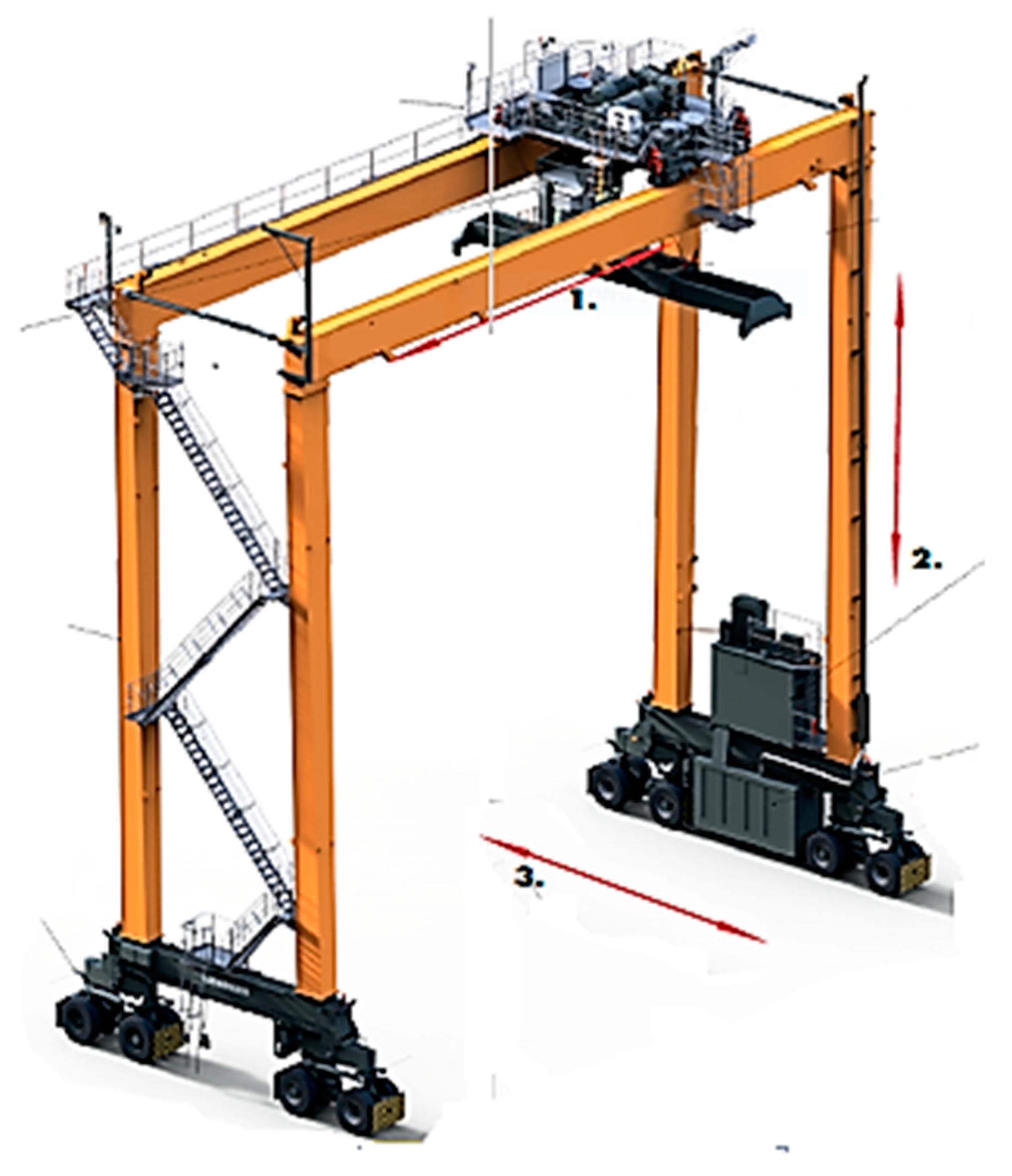
From the 1950s various manufacturers have designed RTG cranes with different specifications to meet customer requirements. The crane used for designing is a standard size crane which has following specification as shown in Table 1. RTGCs have three basic movements. These three steering functions can move 20 ft, 40 ft and 45 ft containers in all directions as shown in Figure 1. Typically for a loaded crane, gantry movement is restricted by terminal operators due to safety concerns. There is a high risk for crane to tip over when moving (traveling) with a heavy container. A conventional RTGC has a diesel generator which delivers power to trolley mechanism, hoist, gantry and auxiliary systems such as control power, air conditioning, lighting systems and hydraulic systems. In conventional RTGCs, a diesel engine coupled to a synchronous generator which operates at 50 Hz or 60 Hz is used as the main power source.
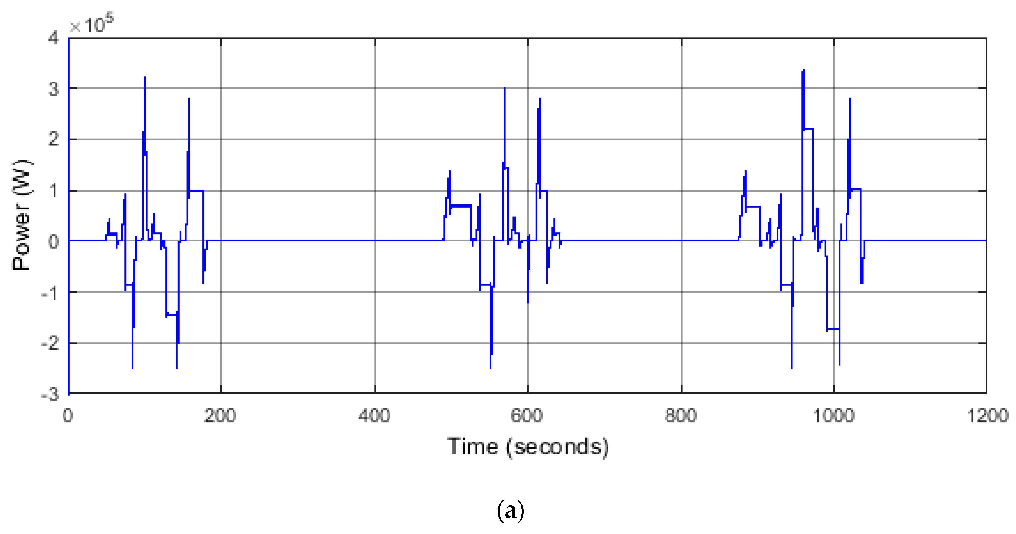
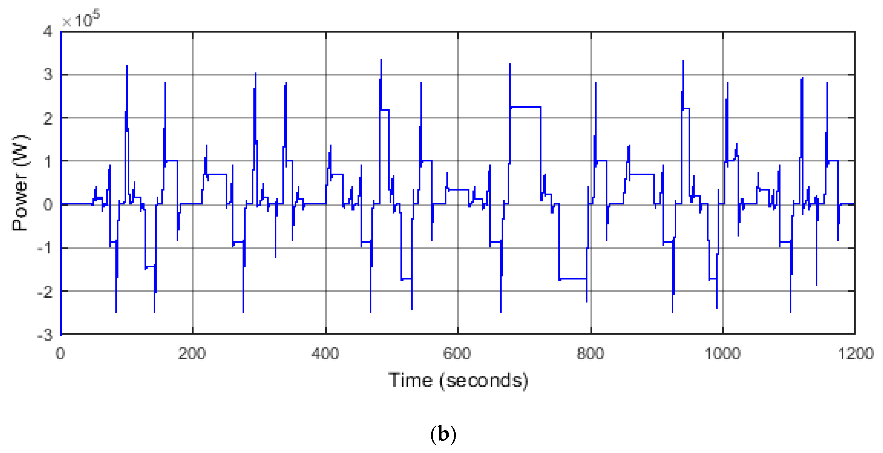
This 3 phase supply is rectified through a diode bridge, thyristor converter or by an active rectifier to feed a capacitive DC bus typically rated above 650 V. In diode and thyristor rectifiers DC bus voltage setpoint is adjusted by generator automatic voltage regulator (AVR) and in active rectifier, the setpoint can be varied digitally where boosting is done with a help of an inductor between generator and active rectifier. All mechanisms are driven by inverter-controlled induction motors. A 180 kW, 8 pole induction motor is used as the hoist motor which can operate safely under 1.8 overload margin. One 35 kW, 4 pole induction motor and four 25 kW, 4 pole induction motors are used in trolley and gantry respectively. DC bus is equipped with a dynamic braking unit to dissipate excess energy as heat during regeneration. Figure 2a,b show the operation cycle followed by the RTGC in quiet and busy operations, which are considered in the design of hybrid system and energy management strategy.
Existing hybrid systems consist of diesel generator with either SC bank or battery bank. Typically, a conventional RTGC is equipped with a constant speed genset rated above 400 kW even though the average generator power demand of a RTGC (50 kW) is comparatively low compared to peak power demand. Therefore, conventional RTGC genset operating at constant speed is highly inefficient at low power demand. A hybrid RTG equipped with a variable speed diesel genset (VSDG) rated at 200 kW and a Li-ion battery bank with 13 kWh capacity has an average monthly fuel consumption of 9.7 l/hrs, which reduces fuel consumption by 50% [9,10] compared to conventional RTGs. Variable speed diesel generators have a slow response compared to conventional constant speed generators. Therefore, most hybrid systems with VSDGs use either battery bank or SC bank to regulate the DC bus voltage where energy buffers are subjected to transient power peaks. Although SCs are highly fit for the purpose, they are rarely used due to its low energy capacity and high cost. Battery systems need frequent maintenance and cell replacement where cells get internally damaged due excessive power peaks. To overcome the above-mentioned drawbacks, a new hybrid energy source comprised with VSDG, battery bank, and SCs with a new energy management system is presented. Several factors are considered for an accurate hybrid system sizing. The diesel genset’s rated maximum power must be grater than the average power demand of the RTGC during operating cycle to overcome the excessive drop of the state of charge (SOC) of SCs and battery. If not, the operating modes of the diesel genset and hybrid energy storage system (HESS) must be considered, due to differences between dynamic response and specific energy (kWh/kg). In this work, a new hybrid architecture is considered for the RTGC includes a 200 kW diesel genset combined with a Li-ion battery and SC bank.
3. VSDG-Battery-SC Hybrid System
Unlike road vehicles, the demand profile of RTG is highly predictive due to its limited operation inside a container terminal. The sizing of VSDG, battery bank and SC bank are carried out by analyzing the most power consuming operation where a 41 t container raised from prime-mover over six containers and stored far bottom end of the stack, which is shown in Figure 2b from 650 s to 830 s. A maximum steady power of 265 kW including 30 kW auxiliary power is demanded during operation. By analyzing the previous hybrid systems discussed in [2,3,4,5,7,10], a 200 kW VSDG was selected with prime power rating where 10% overload capability is available for a 1-h period within a 12-h cycle operation as the main energy supplier for the proposed hybrid system which downsizes the capacity of a conventional generator set by 50%. The proposed VSGD based on the design presented in [10] which have several advantages over other systems. A 200 kW diesel engine is a mid-range engine which has a comparatively large market in trucks, busses, excavators and marine applications which reduce investment cost and operational costs due well-established spare parts market. Secondly, VSDG and battery system can be compact to a single unit system under one canopy which is enormously useful due to space constraints in the RTG crane (typically, the genset canopy and electrical room are mounted on two sill beams of the two legs).
The battery is sized to fill the gap of 65 kW between maximum steady power demand and VSGD capacity. Considering the overload margin of the VSDG, a battery bank capable of delivering continuous power of 55 kW is selected on the design. The selection of battery chemistry and cell-modules are discussed in Section 3.1.
The SC capacity was evaluated under 5 facts. They are peak transient energy requirement during hoist acceleration under 41 t, supercapacitor state of charge bottom margin, supercapacitor state of charge operating point, an energy buffer as a safety factor and max energy requirement during time delay introduced between two states in Energy Management System (EMS). A minimum SC capacity of 0.468 kWh was achieved by calculating the peak transient energy requirement as 0.0854 kWh from demand model, SC SOC bottom margin as 30%, SC SOC operating point as 70%, energy buffer as 2, and max energy requirement during time delay introduced between two states in EMS as 0.0166 kWh.
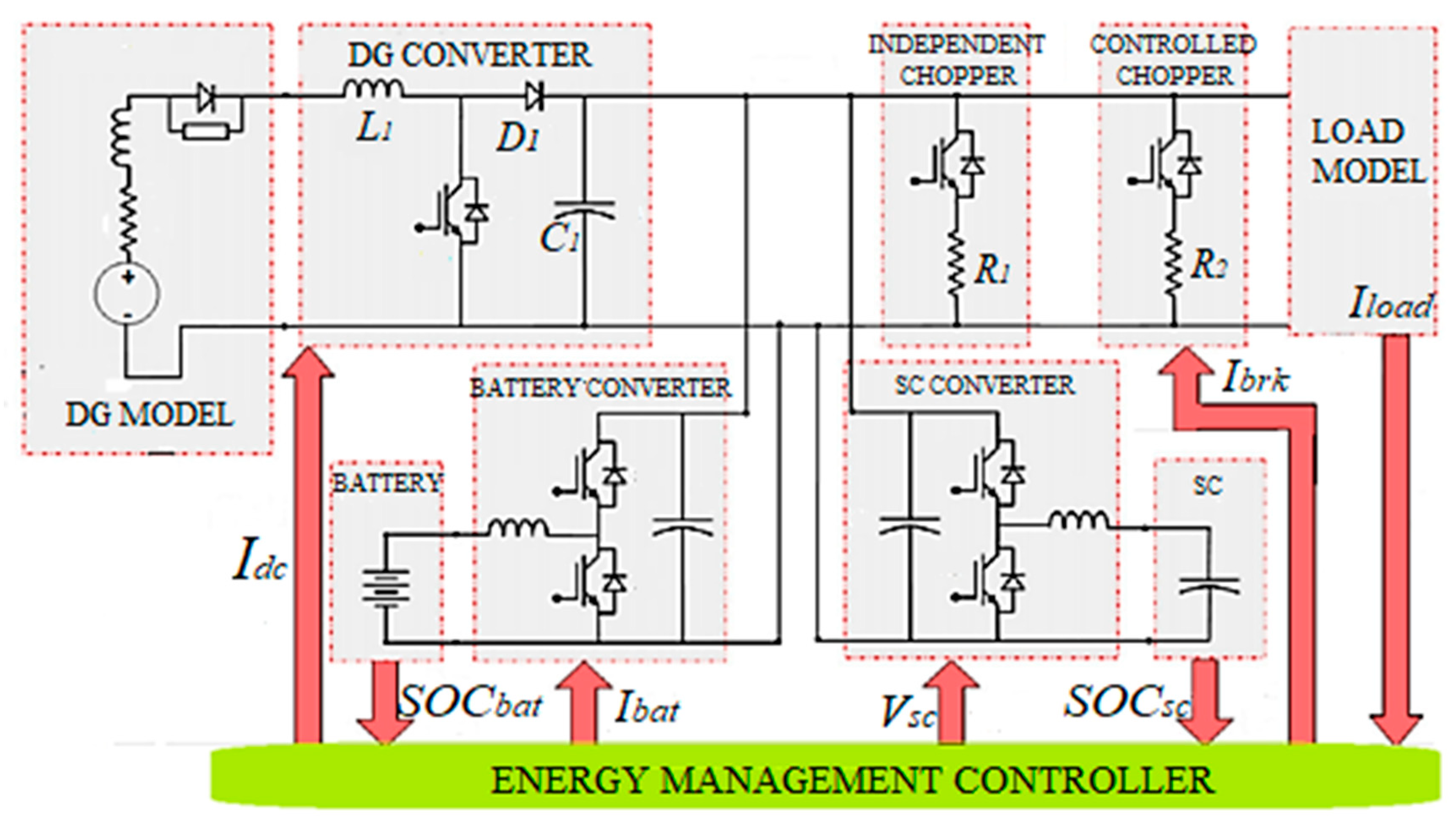
Therefore, proposed topology for the hybrid RTGC is powered by 200 kW VSDG capable of undergoing 10% overload, 55 kW Li-ion battery bank and 48.3 F SC bank is shown in Figure 3. The battery bank and SC bank are integrated through 60 kW and 250 kW DC/DC converters, which connect them to the capacitive DC bus. During regeneration, a portion of regenerated energy can be stored due to limited power capacity of battery bank and energy capacity of SC bank. Therefore, additional energy during regeneration is dissipated through controlled braking chopper and another braking chopper is placed to control the DC bus voltage independently in an event of overvoltage of DC bus.
The VSDG is the primary energy source of the proposed hybrid system. The generator output is connected to unidirectional active rectifier which raises the 3 phase AC voltage to standard DC bus voltage. Contrarily, a rechargeable Li-ion battery bank and a SC bank are used as energy buffers where they can be used to supply extra power when needed and to supply power during idling period. Because of the high dynamic response of the SC bank, it can inject or absorb peak power notches that cannot be supplied from battery and VSDG. As the Figure 3 illustrates, 7 signals are used to run the energy management strategy. The sizing of capacity of VSDG, Li-ion battery bank and SC bank is not heavily discussed to keep focus on the energy management strategy.
3.1. Battery Model
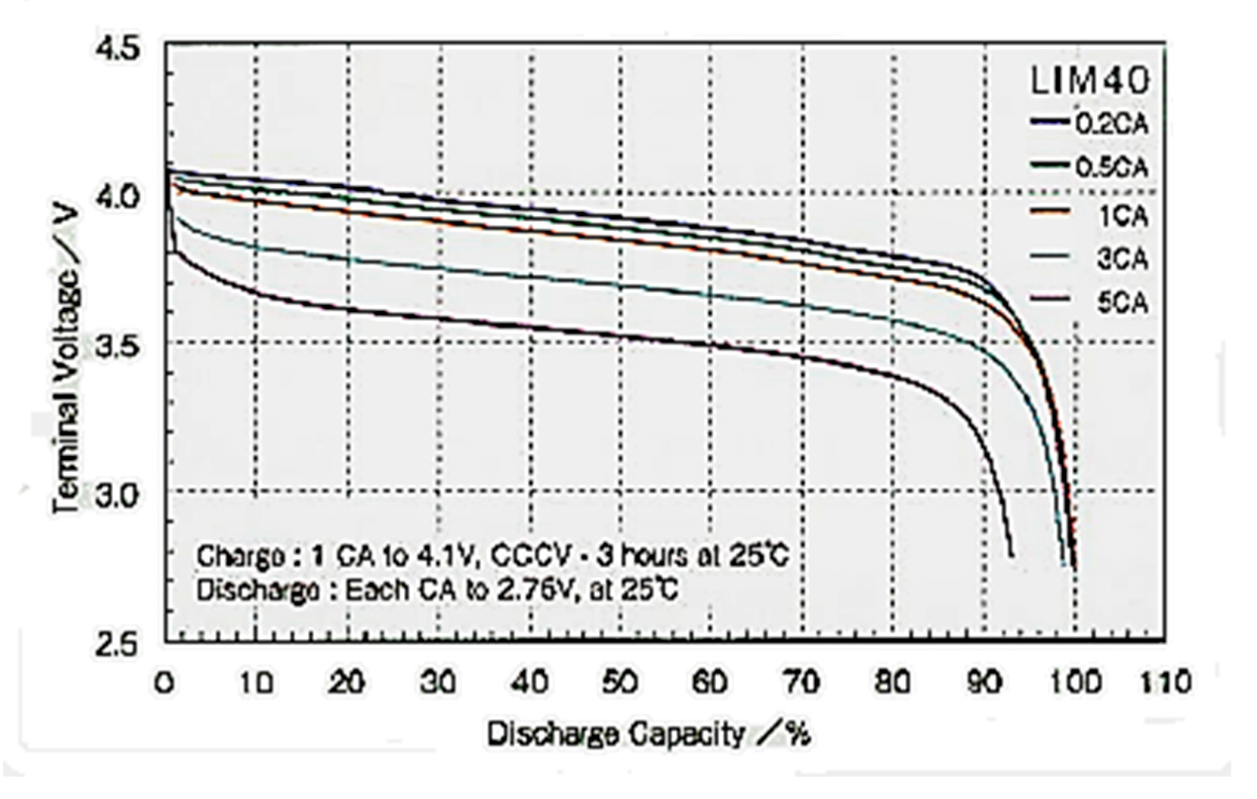
Batteries are heavily utilized as energy storage device in many applications. Presently hybrid vehicles, hybrid ferries, hybrid equipment (cranes), shunters, and tramways are equipped with different types of batteries such as Pb-Acid, Ni-Mh, Ni-Cd, and Li-ion batteries. Li-ion batteries have better response than Pb-Acid, Ni-Mh, and Ni-Cd batteries. Furthermore they have higher energy density, high power density and higher life cycle. Li-ion batteries can be categorized into several subcategories according to their chemical composition. Lithium Cobalt Oxide (LiCoO2), Lithium Manganese Oxide (LiMn2O2), Lithium Nickel Manganese Cobalt Oxide (LiNiMnO2), Lithium Iron Phosphate (LiFePO4), Lithium Nickel Cobalt Aluminum Oxide (LiNiCoAlO2), and Lithium Titanite (Li4Ti5O12) are some of them. GS YUASA’s LIM40-7D 26.6 V, 40 Ah [11] battery module is considered for the hybrid RTGC battery bank. The battery module consists seven cells each having ratings of 3.8 V, 40 Ah. The cells are made from LiMn2O4 as the positive active material and hard carbon as negative active material [11]. The operation of Li-ion battery cell has been presented by the model in Simulink under Simpowersystems library [12]. In this model, cell is represented by its equivalent circuit, a variable source in series with a resistor. The voltage value of the variable voltage source is calculated using a discharge model and a charge model, depending on how the battery is discharged and charged. The models for Li-ion cell have been developed considering Lithium iron phosphate cell in [13,14,15]. The discharge model of Li-ion cell used in Simpowersystems has been developed in [16] and it can represent accurately the voltage dynamics during current variations. The cell open circuit voltage (OCV) during discharging (i* > 0) is given by,
where is the cell OCV (V), is the battery constant voltage (V), is the polarization constant (V/Ah) or polarization resistance (), is the battery capacity (Ah), A is the exponential zone amplitude (V), B is the exponential zone time constant inverse ((Ah)−1), is the battery current and is the filtered current.
During charging voltage increases rapidly when cell reaches full charge. This is modeled by the polarization resistance term. Experimental results have shown that the contribution of the polarization resistance is shifted by about 10% of the capacity of the cell. The Equation (2) presents the OCV during charging of a Li-ion cell where is the OCV during charging. Cell terminal voltage can be calculated by subtracting the voltage drop due to internal resistance from the OCV. Therefore, cell output voltage, can be calculated as follows:
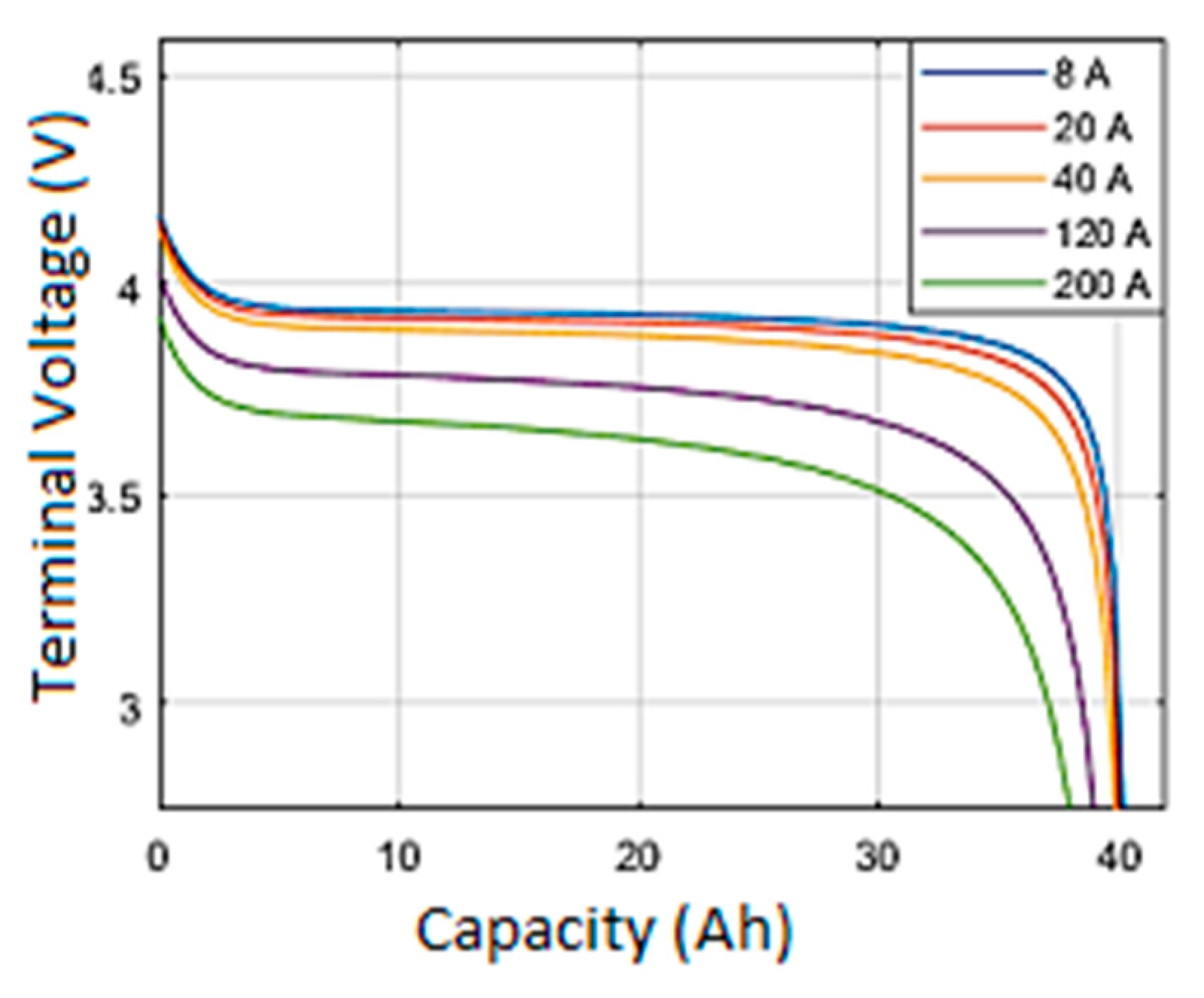
where represents OCV during discharging or charging and cell internal resistance is . Figure 4 presents the actual current discharge curves for different C rates for LIM40-7D cell. The discharge curves for the model for the same C rates are presented in the Figure 5. The model characteristics do not match one to one with actual characteristics. The variations are quite large at the end of exponential zone, which may not directly influence the final design. On the other hand, the battery SOC must be kept between 35% and 90% to minimize capacity fade.
Therefore, the energy management system will be developed to operate the system within above range, so that the battery model is considered to be valid for the design. A set of 14, LIM40-7D units is selected to construct the battery system and all units are connected in series to obtain the maximum battery system voltage which is 372 V. Battery side discharging and charging currents were limited to 150 A for safe operation [11]. Referring to the above maximum discharging and charging currents, max power rating can be calculated as 55.8 kW.
3.2. Supercapacitor Model
Supercapacitors have shown their capability in energy storage for special applications. They are used in applications requiring rapid charge/discharge cycles rather than long term compact energy storage in trams, trains, grid voltage stabilizers, cranes, and elevators. Unlike conventional capacitors, SCs do not use solid di-electric, but rather they use double layer technology. The charge and discharge pulse characteristics can have current pulses as high as 1000 A and their pulse duration ranges from several milliseconds to tens of seconds. SCs have pros and cons compared with Li-ion batteries. They offer high power density, high cycle life and wide operating temperature range during operation. Due to low energy density and low cell voltage of SCs, space requirements are high compared to Li-ion battery. Unlike batteries, terminal voltage of SCs varies in a broad range during operation. Therefore, a DC/DC converter should be used to interface a SC bank to DC bus. Maxwell K2 ultracapacitor cells 3.0 V, 3000 F [17] is considered for hybrid RTGC SC system. The cells are specially designed for heavy transport applications such as buses, cranes, and rail applications. The operations of SC system have been presented by the model in Simulink under Simpowersystems library [18]. In this model, the capacitor is represented by its equivalent circuit: a controlled voltage source in series with a resistor. The voltage of controlled voltage source is calculated using the Stern equation [19] and self-discharge was neglected for simplicity. The Stern voltage is given by:
where is interfacial area between electrodes and electrolyte (m3), is molar concentration, is Faraday constant, is supercapacitor current, is molecular radius, is number of layers of electrodes, is number of parallel supercapacitors, is number of series supercapacitors, is ideal gas constant, is operating temperature (K), is permittivity of material and is the permittivity of free space. Cell terminal voltage, can be calculated by subtracting the voltage drop due to internal resistance from the controllable voltage source. Internal resistance can be modeled as a function of temperature. In practical design, complete energy storage system includes active temperature control system. Therefore, effect from temperature fluctuations for internal resistance can be neglected. Therefore, cell terminal voltage is given by:
where is the internal resistance. Therefore, cell terminal voltage depends on the demand current and SC state of charge, given by,
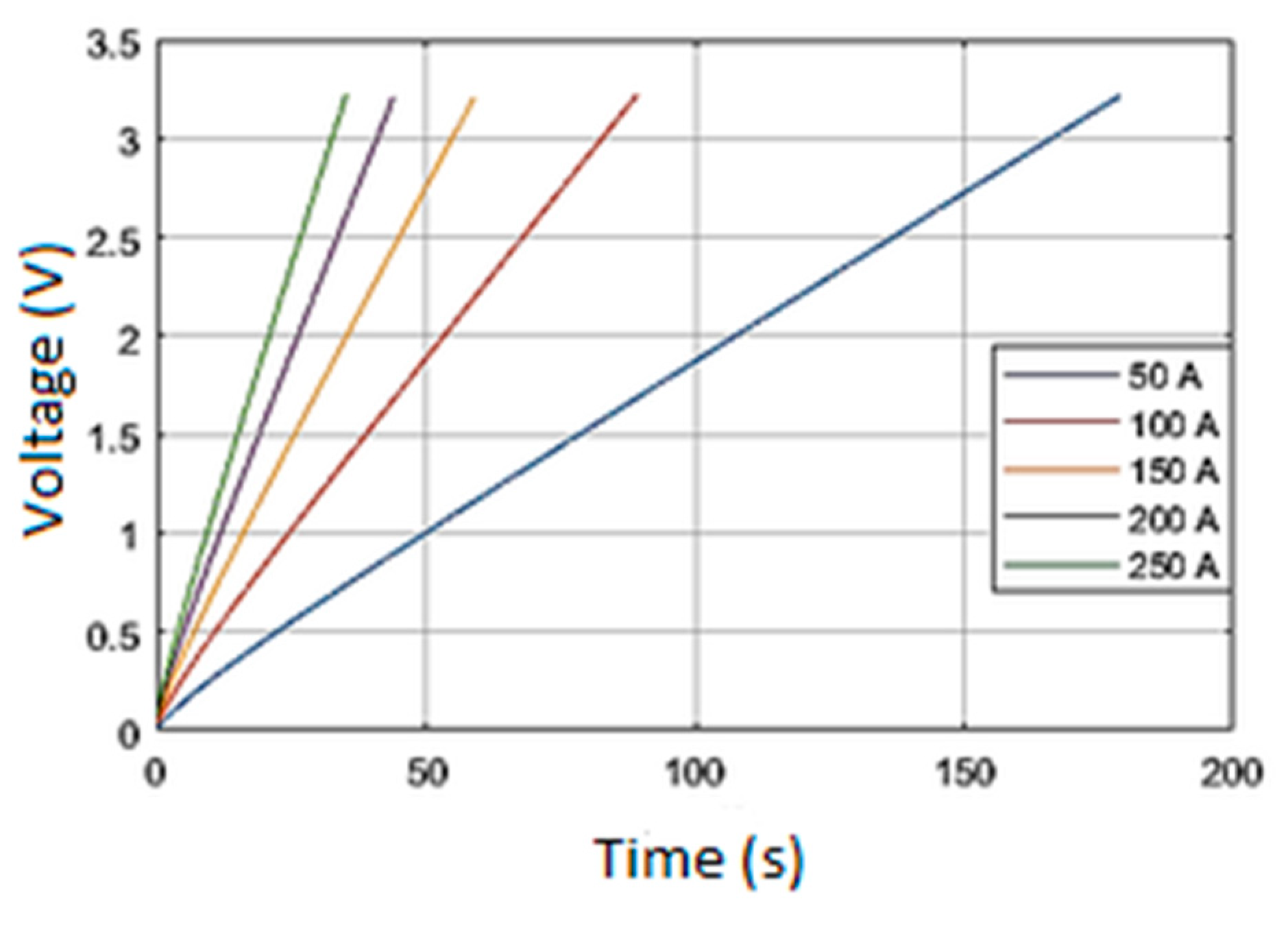
where is the initial electric charge, is the cell capacity and is the rated cell voltage. Figure 6 shows the SC charge curves for different currents for the proposed SC model. However, the model does not exhibit any non-linear behavior as actual characteristics in [18] where tests were done for a 125 V, 63 F Maxwell supercapacitor module. Their non-linearities are quite high at low voltages compared to rated voltage in [20]. However, these non-linearities may not influence, because in practice SC systems are not drained below quarter of its rated voltage. Therefore, SC model can be considered as a valid model to represent the response of HESS.
3.3. Diesel Generator Model
Diesel generator (DG) is the prime energy supplier for most of the RTG cranes. Typically, a 600 kVA generator [21,22] is installed in a conventional RTGC to accommodate peak power demands. Most of the RTGCs have a DC bus to supply electrical power to all subsystems. Therefore, DG clearly operates as a DC supply rather an AC supply. Due to this configuration, dual speed generators and variable speed generators are highly popular for RTGCs where generator frequency is not a governing factor for crane system. For the proposed system, variable speed diesel generator is used considering the presence of energy buffers (SC and Li-ion battery). Commercially available VSDG systems change engine speed according to the load. In most commercial systems, the VSDG controller specified speed limits for specified load limits. These limits are calculated evaluating the brake specific fuel consumption of the engine. In the proposed system the SC system can handle transients where dynamic response of VSDG is not very much crucial. Therefore generator and battery bank should be able to supply steady-state demand under 41 t container with rated hoisting speed. Maximum continuous generator demand () can be calculated as follows.
where is the maximum steady-state hoist power, is the maximum auxiliary power and is the continuous battery power. Thus, the peak generator continuous power is then,
Analyzing the behavior of power demand, energy usage of diesel genset and fuel consumption is the prime importance for the modeling. Considering the response time from idle speed to rated speed under no-load condition, a 50 A/s current rate limiter was introduced to active rectifier where VSDG takes 6 s to reach no-load to full-load. Therefore, modeling the thermodynamic behavior of the engine, dynamics of governor and controller, dynamics of the synchronous generator and AC/DC converter are not necessary to measure fuel consumption of the VSDG.
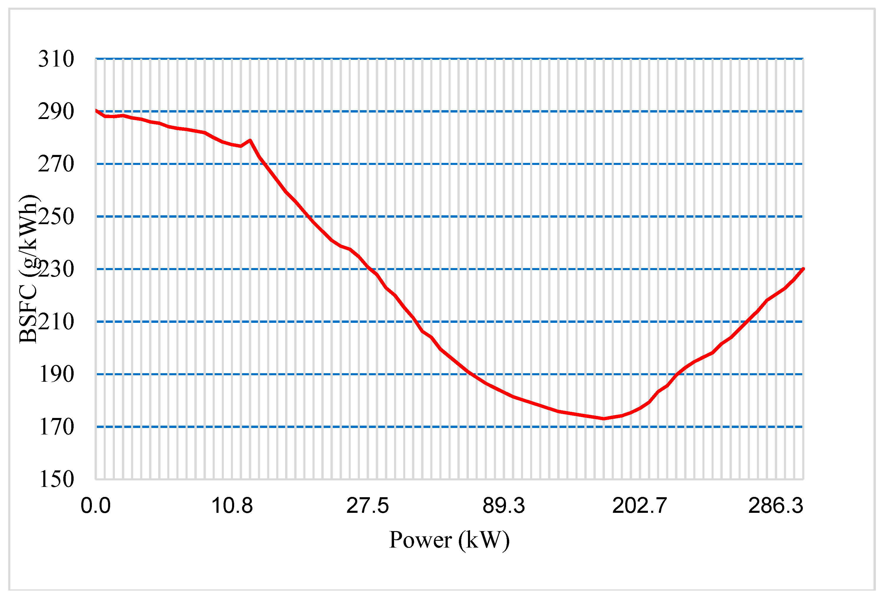
Considering above facts, DG model was created with a simple DC source with a serially connected resistor and an inductor to represent equivalent winding internal resistance and inductance. The active rectifier is modeled as a unidirectional DC/DC converter with average modeling technique in Simulink environment. The test fuel consumption data presented in [5] for a 300 kW VSDG is used and modified to evaluate the consumption which is shown in Figure 7.
3.4. DC/DC Converter Model
The terminal voltage of energy sources (SC, Li-ion, and battery) fluctuates according to their demanded power and SOC. Thus, a power electronic system is needed to control the output power of the sources where the power demanded by the system keeping the DC bus at constant. A special power electronic system composed of a PWM (pulse width modulation) based bi-directional DC/DC converter is used to interface each energy source with the DC bus. This bi-directional DC/DC configuration allows the energy transmission in both directions, from the battery or SC to the DC bus, and vice versa. In industrial applications interleaved DC/DC converters are highly used due to their inheriting advantages on low output current ripple broad input voltage range [23]. Unlike battery systems, SC banks SOC is tightly linked with the terminal voltage. Therefore, minimum operating voltage of the DC/DC converter is quite important for a SC bank.
The minimum operating voltage of the DC/DC converters are taken as 50 V [24] considering market available systems even some commercial systems capable of operating 0–800 VDC [25] input voltage. In practical conditions, DC/DC converter automatically disable before SC bank reach deep discharge. Average modeling can reduce the complexity of interleaved DC/DC converters to quite an extent.
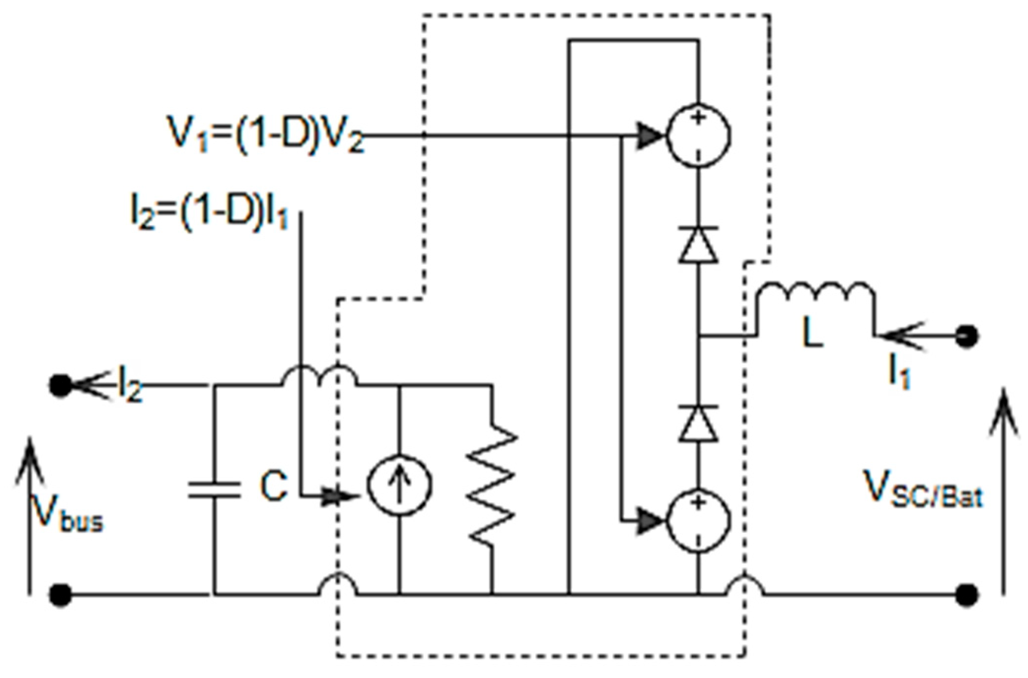
The two-quadrant DC/DC converter model of SimPowerSystems [26] is used to model the converters. Figure 8 shows the average value equivalent model of the converter where power electronic switches are represented by current and voltage sources. The equivalent model consists of a controlled current source at the DC bus side and a controlled voltage source at the battery, SC, or DG side. The average model provides fast simulation where switching function model is directly controlled by the duty without a PWM generator.
3.5. Brake Chopper Model
During lowering, most of the regenerated energy is stored in the battery and SC. However, when the battery and SC or SC itself achieve the charge limit, power absorbing capability reduces drastically. Therefore, to maintain the DC bus voltage, this excess energy must be dissipated. A braking resistor is used to dissipate excess energy where IGBT (Insulated Gate Bipolar Transistor) chopper is used to control the current through the braking resistor. The HESS determines the instantaneous value of power that should be dissipated within the braking resistor. Another braking chopper is placed to control the DC bus voltage independently in an event of overvoltage of DC bus under system abnormal conditions.
3.6. Auxiliary System Model
The auxiliary systems, such as air conditioning systems, control power, lights for night time operation and wheel turning hydraulic pump motors contribute to auxiliary power. These systems have more or less power demand of 10–30 kW depending on environment variables, e.g., temperature and daylight. Considering the worst-case scenario, auxiliary power consumption of RTGC is modeled as a 30 kW constant power load. In this paper, for the simplicity, this load has been modeled as a controlled dc current source connected to the dc bus, whose current is a function of the power consumption and the DC bus voltage.
4. Energy Management System (EMS)
The existing hybrid systems are designed using constant speed generators combined with either supercapacitor/battery systems or variable speed diesel generators combined with either SC/battery bank. Due to the inherent characteristics of SCs and batteries, sizing high energy capacity with SC system or sizing high power battery system may not be an economically viable solution. Most of the existing hybrid systems consist SC bank with very low energy capacity where crane have to de-rate its performance when SC bank reach its critical level. Systems with batteries have low life span due to high pulse current discharges which are beyond its recommended conditions [27,28]. Reaching very low SOC levels or overcharge conditions [29] during faulty conditions or abnormal conditions can reduce the available capacity (capacity fade effect). The proposed system uses SC sub-system to filter transient demand from VSDG and battery system while energy management system using a unique technique to keep battery system under healthy condition. Typically, battery systems are constructed connecting individual cells in series or parallel to match the voltage and capacity. When maintaining terminal voltage of a large serially connected battery bank, cell voltages may differ due to various facts. To avoid large deviations in cell voltages, cell balancing systems are adopted. Due to the imperfections of these systems, control algorithms or abnormalities on some cells, still there is a high chance that some cells experience overvoltage when battery bank SOC reach close to 95% which accelerate capacity fade effect of the overvoltage cells [30]. During lower SOC levels some cells reach low cell voltages due to SOC estimation errors or malfunction in balancing system. Unlike pure electric vehicles, hybrid systems have flexibility to select and modify battery SOC operating region. Operating battery bank SOC under a narrow band can reduce the potential of risk reaching over voltage and under voltage condition for individual cells even under faulty conditions and abnormal conditions. Table 2 and Appendix A present the capacities of individual components and their control limits.
This section has been organized in four subsections. The top three sub-sections describe the operation of VSDG, SC and battery. The last sub-section explains the state machine controller which generate the appropriate reference control signals for VSDG, battery, SC and braking chopper processing the input states of SC, state of charge, battery state of charge and real-time demand current which is sampled at a rate of 10 kHz.
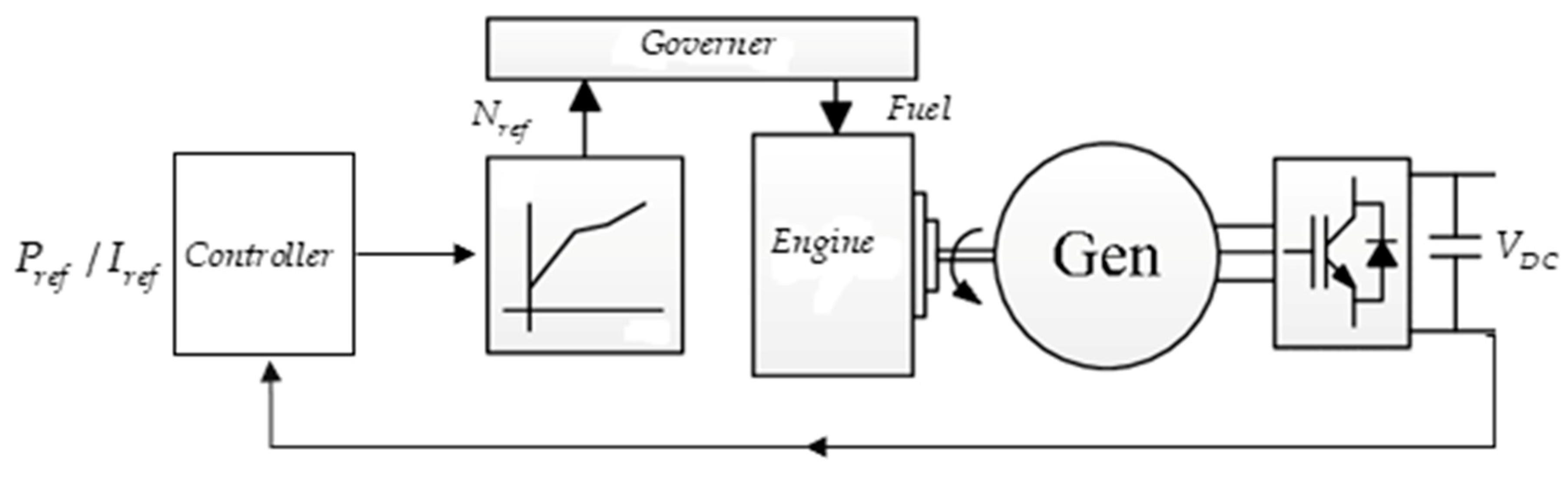
4.1. VSDG Control
VSDG has poor time response compared to constant speed generators. Typically, VSDG maintains engine speed closer to idle speed during no load condition. According to real-time, demand the system adjusts the engine speed optimizing fuel consumption as shown in Figure 9. In practice, discrete speed set points are given for optimal power ranges [10] and even under light load conditions VSDG maintains considerable high fuel efficiency [31] compared to constant speed generators. VSDG converter, (active AC/DC rectifier in actual system) can be controlled in two modes, namely controlled current mode and constant voltage mode. The modeled system operates as a controlled current source where dynamic current variation restricted to 50 A/s. The slow dynamic response (50 A/s) helps to reduce partially burned exhaust gas during engine loading and modeling can be simplified to equivalent DC source with series internal resistance and inductance.
The fuel consumption test data published in [5] is used to model the fuel consumption dynamics along with total consumption for proposed simulations. The maximum current is set to 330 A in which generator is overloaded by 10%. A PI controller regulates the current output according to the setpoint given by the EMS.
4.2. SC Control
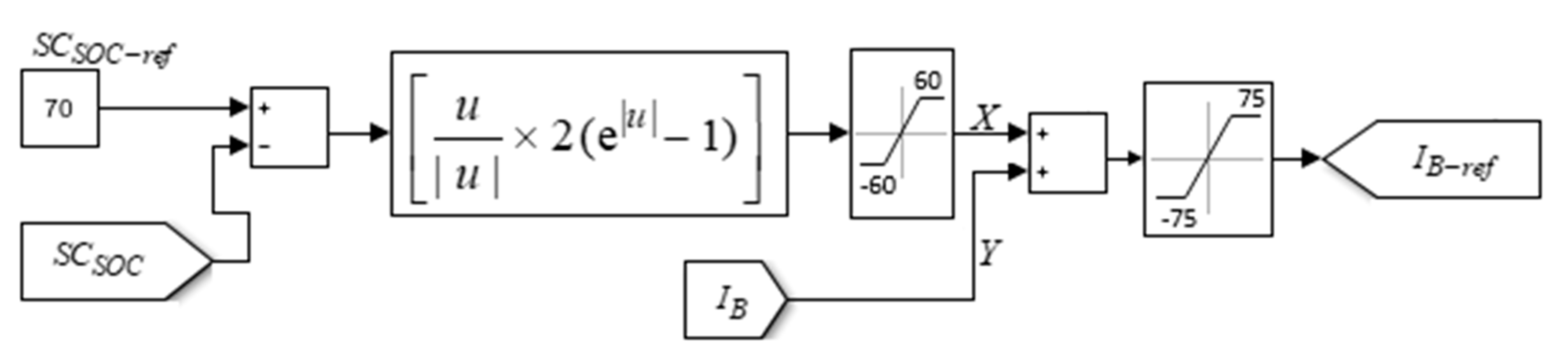
The SC converter operates as a constant voltage controller which primarily maintains the DC bus voltage. A closed loop PI controller determines the suitable duty factor for the SC converter to maintain the DC bus voltage, where SC bank voltage varies heavily with SOC level. As the system demands power from the SC bank while trying to maintain the DC bus voltage, the duty cycle of the SC converter increases so that the SC bank voltage decreases, and the SC bank is discharged. Therefore, SC system along with DC/DC converter is modeled with fast response with a reaction time less than 700 us and operating under a broad input voltage range. The commercial systems have capability to respond less than 500 us where they can operate as low as 100 V input voltage [24,25,32]. Two types of peaks are possible within the system during operation: positive power peaks due to acceleration and negative power peaks due to deceleration. The negative power peaks do not contains much energy. Trying to save energy of negative power peaks during deceleration may not be economical. But during acceleration, energy for positive power peaks must be supplied to avoid degrading performance of the system. To cope with uncertainty of power peaks, SOC of the SC should be maintained at a higher value. During the design process, a SOC level of 70% is selected considering negative transient regenerative energy impulse during hoist deceleration and positive transient energy impulse (0.0854 kWh) due to hoist acceleration. The SOC level of the SC bank is maintained by controlling the power flow of the battery bank via proposed numerical estimator shown in Figure 11 where represents the control command for battery converter. Therefore, is given by,
where u is the SOC error and , battery current command from state controller. The numerical estimator generates a bounded () exponential current reference according to SC SOC error. During operation, the demand current determines net current that SC bank may charge and in some instant, a considerable time lag may be introduced during continuous high demand currents.
4.3. Battery Control
The battery control determines the suitable duty cycle of the battery converter to maintain the current requested by the EMS, while the battery terminal voltage varies depending on the operating mode (charge or discharge) of the battery. The battery side current is limited to 150 A (3.75 C) for discharging and charging. The battery current reference () is coupled with two parameters, namely SC SOC level and demand current as discussed in Figure 11 and Equation (8). The priority is given to demand current where remaining current portion is naturally absorbed or give out by the SC DC/DC converter due to its constant voltage control mode.
Usually, industrial Li-ion battery systems are managed by battery management systems (BMS). BMS individually monitors each cell voltage and balance if necessary. Typically, BMS systems are responsible for estimating state of charge of the battery systems. In proposed system, battery SOC is controlled by the state machine controller and a SOC level-based hysteresis band is introduced as the charging and discharging algorithm. Three different charge-discharge scenarios are introduced by the state controller as shown below.
- Charge the battery bank from VSDG up to 60% (upper margin) SOC, when bottom margin detected by the state controller
- Support the steady state demand along with VSDG until SOC reaches its bottom margin (40%)
- Interrupt the charging process and contribute to demand when demand current is extensively high (e.g., when demand current reaches above 270 A)
The battery SOC level is controlled in a narrow band 40–60% to avoid 100% deep discharge during failures. During the operating lifecycle, a tolerable capacity fade could introduce SOC estimation errors which may lead battery system to be deeply discharged. Hence the situation is avoided using 40% SOC margin for the bottom end. During charging mode, battery bank experiences a 3.75 C continuous charging current that may increase the internal temperature of the battery system. The 60% upper SOC margin limits the charging capacity approximately to 2.9 kWh (>1.86 kWh, average electricity consumption per move for electrified RTGC) which controls the heat generated during constant current charging while minimizing the energy losses due to round trip efficiency of the battery and converter system.
4.4. State Machine Control
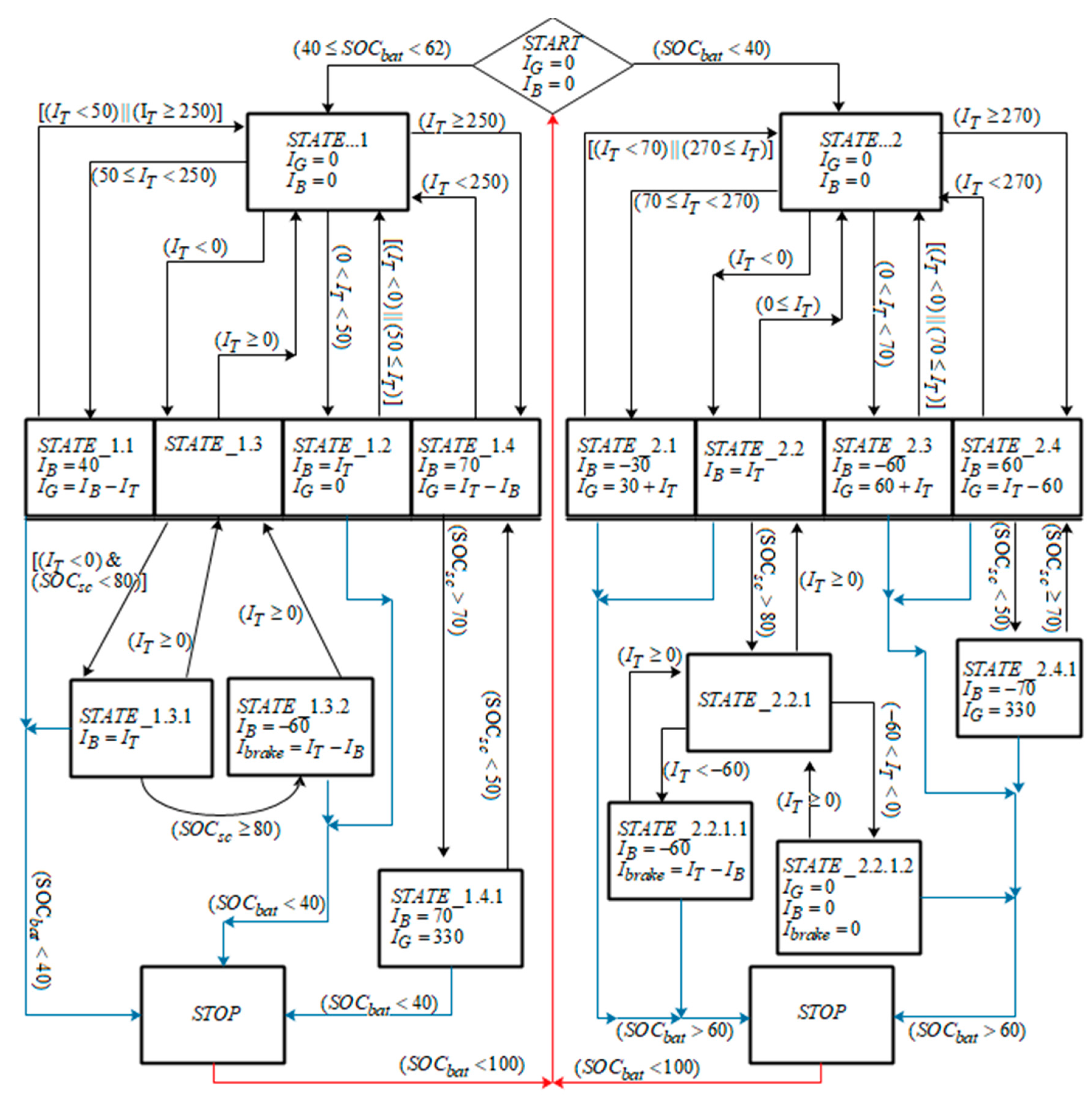
In Figure 10 the decision-making process of the state machine is displayed. The state machine control has the advantage that it is relatively easy to understand what is happening in the process of selecting the set points for Li-ion battery, SC, and VSDG. State controller is mainly based on two conditions to decide the operating point for each converter of the hybrid system.
Two levels of battery SOC have been considered: low SOC (<40%, state 2) and normal SOC (40%–60%, state 1) where battery SOC is controlled within a narrow band of 20%. The algorithm generates reference current setpoints for VSDG, battery and corresponding current command for power to be dissipated in the dynamic braking resistor. Since the VSDG dynamic response is low, the system tries to avoid the rapid changes in the VSDG system. The changes in the reference current set points will occur when system components reach their limits. The controller determines the operational state according to the demanded current of RTGC subsystems and battery SOC level. Battery SOC is maintained between 40% and 60% while SOC of SC is maintained at 70%.
The structure of state controller is shown in Figure 10 where is generator current set point, is total current feedback from the system, is battery current set point, is current set point for braking chopper, is the SOC of battery and is the SOC of SC. A 0.2 s time delay is introduced between state transitions to avoid toggling between states. During time delay, the additional power requirement is supplied by the SC bank. The operation of two main conditions are described as below. The total steady-state current demand of the system is given by,
where SC current is not considered due to its absence in steady state. Therefore, supercapacitor current is not present with the diagram and all operational states shown in state diagram full-fill the requirements of Equation (9) onwards.
State 1 (left side of the diagram):
When is between 40% and 60% VSDG operates as an adaptive source. During above battery SOC level,
where total current demand is less than 50 A (state_1.2). As the total demand increases above 50 A, VSDG operates as an adaptive source except for one condition where & shown by state_1.4. The battery and VSDG current set points can be given as (state_1.1 and state_1.4),
The battery converter current reference is given by,
where is the charging current reference output by the SC charge controller defined as in Figure 11. The state_1.4.1 refers to sub-condition where drops below 50% during and VSDG is forced to deliver its maximum power (330 A) until reach 70%. During energy regeneration, SC operates in parallel with battery where there is no limitation for regenerative power level given by,
where is regenerative power, is charging power of battery and is power of SC. State_1.3.1 equalizes the total demand current to battery current where battery converter limits it to where rest of the current naturally absorbed by the SC system due to its constant voltage operation. When SC reaches its max energy level (80%), the extra regenerative energy is dissipated in the braking resistor as shown in Equation (15) and state_1.3.2,
where is negative during regeneration.
State 2 (right side of the diagram):
When drops below 40%, VSDG charges the battery system up-to 60% except energy regeneration mode and situations where demand current exceed 270 A as shown in state_2.4.1. During low demand, the VSDG current reference and battery current reference is given by
where battery is charged from VSDG at an approximate rate of 40 kW which is almost 20% of VSDG rating as presented in state_2.3. The VSDG and battery current references during can be given as
When the demand current exceeds 270 A margin, battery supports the system as shown in state_2.4 and progressing to state_2.4.1 depending the SC SOC condition. During energy regeneration the system operating logic shown in state_2.2, state_2.2.1, state_2.2.1.1 and state_2.2.1.2 is similar to the scenario discussed in Equation (15), operating in parallel with the SC and battery to absorb energy and dissipate energy in braking resistor when SC reaches its maximum SOC level.
5. Simulation Results and Discussion
The proposed hybrid system and the control strategy have been implemented in MATLAB-Simulink (2017a, MathWorks, Natick, MA, USA) and tested for power profiles shown in Figure 2a,b. The system has been simulated for 1200 s which corresponds to complete operation of driving cycle. Figure 2a relates to a quiet operation condition where only three moves are handled within a 20 min period. During that period 30 kW of auxiliary power is considered to simulate the worst-case scenario. A busy operating condition is shown in Figure 2b where 6 moves are done within 20 min period. The most energy consuming move is also included within the system combined with 30 kW auxiliary power demand. To evaluate the EMS under different operating conditions, four simulations were performed covering full range of battery SOC with different demand profiles. The first two simulations demonstrate the system behavior when battery SOC reaches bottom margin and third, fourth simulations cover the behavior when the system starts operating mid SOC range.
- (A)
- Simulation with an initial battery SOC of 38% with quiet operation.
- (B)
- Simulation with an initial battery SOC of 38% with busy operation.
- (C)
- Simulation with an initial battery SOC of 50% with quiet operation.
- (D)
- Simulation with an initial battery SOC of 50% with busy operation.
The proposed VSDG capacity and its operation mode plays a major role to minimize the fuel consumption. The fuel consumption during 4 cases are evaluated using test data published in [5] for a VSDG. The 4 simulation cases record 3.66 L, 4.36 L, 3.38 L, and 4.06 L fuel consumptions respectively as shown in Table 3. An event combining all 4 cases as a single event can be considered to have a broader view about fuel consumption. The event presents a total of 18 moves within an 80-min period where total consumption was calculated as 15.4 L. The fuel consumption per move was recorded as 0.85 L/move. The above result is calculated with 40 hybrid RTG cranes that include 200 kW VSDG and 13.8 kW battery bank [10]. The batch of cranes had recorded a consumption of 1.175 L/move averaging consumption of 2,218,729 moves in 2016. The fuel savings compared to the crane described in [10] and to a conventional RTGC () can be calculated as follows,
where , are the fuel consumption per move for the reference system and fuel consumption per move for the proposed system respectively. According to Equation (18), a 27% reduction compared to hybrid system discussed above and 57.5% reduction compared to conventional RTG crane where conventional cranes consume 2 L/move can be calculated.
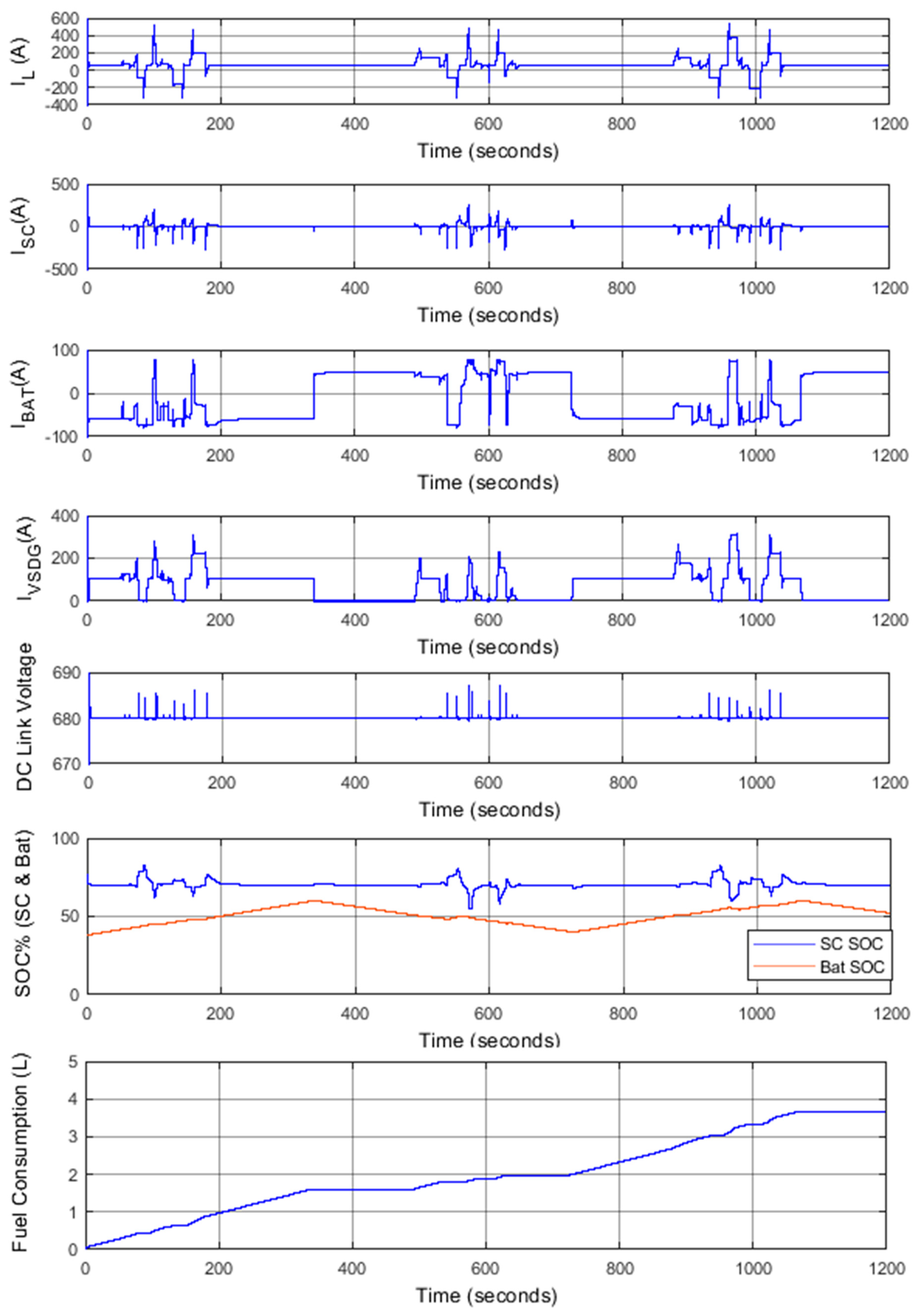
A. Case 1: Simulation with an initial battery SOC of 38% with quiet operation
In this case, it was considered an initial battery SOC of 38%, so that the battery starts to charge to upper SOC threshold, in which both the charge and discharge of the battery and SCs are allowed. Quiet load profile was simulated on the system where Figure 12 shows the SOC variations of battery and SC, the current variations of DC bus, battery, SC, and VSDG. A distinct variation between SOCs of battery and SC can be seen where battery SOC has a smooth profile due to its higher energy capacity. SC SOC variations have a broader band due to its low energy capacity. Maintaining SC SOC is important because charging above 100% could destroy the SC and discharging below 25% could make unstable the DC bus voltage. In Case 1, SC SOC is maintained between 95% and 25% where DC bus voltage is unaffected. The fast-dynamic response of SC makes the battery and VSDG currents smooth where battery discharging and charging currents limits (−75 A/75 A) are maintained as expected. The VSDG’s 50 A/s slew rate needs 6 s to reach rated power. However, this slow response has not affected to the system operation during Case 1 while maintaining the limits as expected.
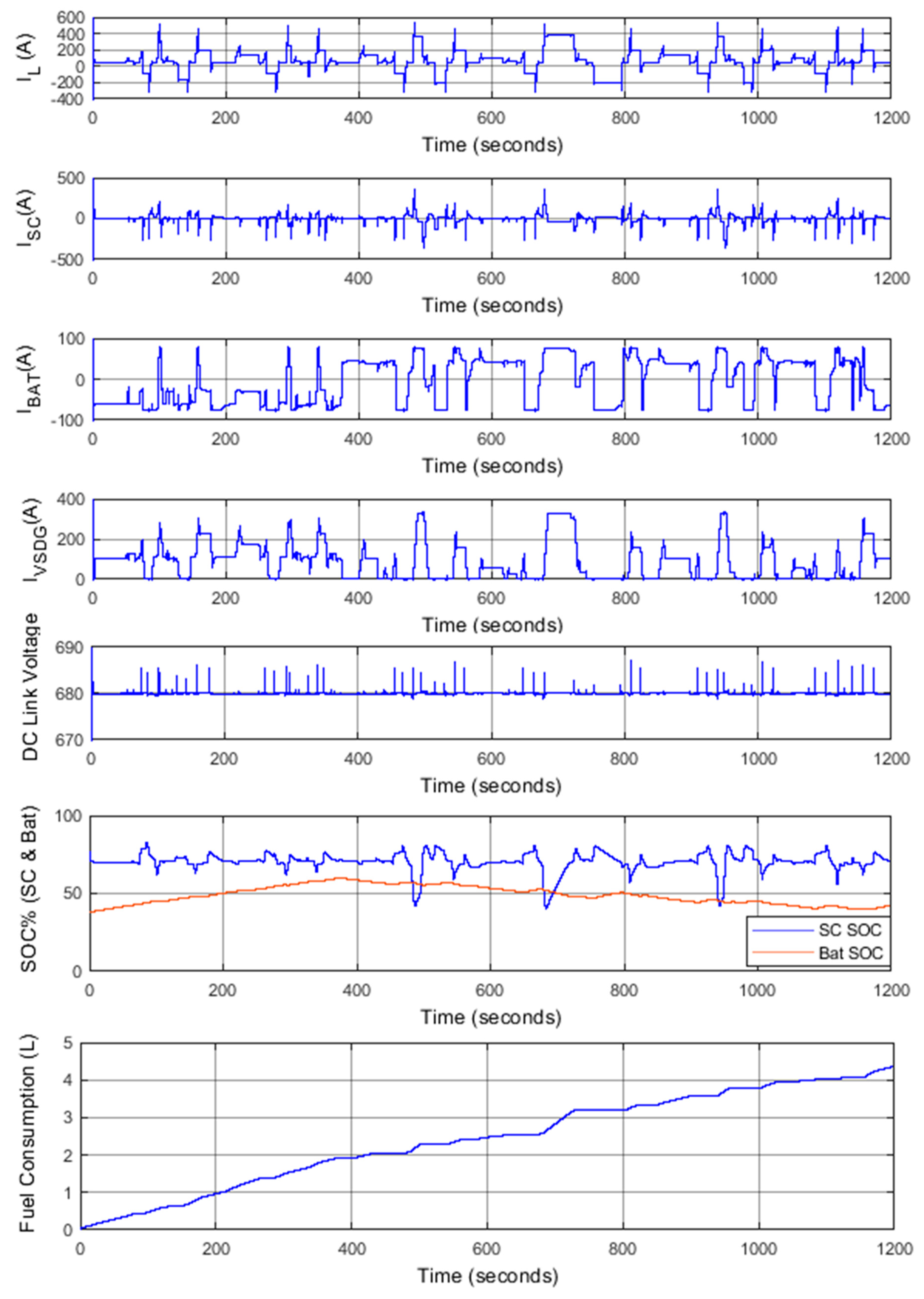
B. Case 2: Simulation with an initial battery SOC of 38% with busy operation
In this case, the battery starts to work with low SOC of 38%, and therefore, its discharging current must be minimized as Case 1. The simulation results are shown in Figure 13. During the first 350 s, the battery gets charged due to its low initial SOC and therefore, EMS adapts sub-states of state 2 where battery is forced to charge by the VSDG. From 350 s to 750 s the battery supports the system by discharging and charging during regeneration. During regeneration, EMS moves to state_1.3.1 and state_1.3.2 to charge battery and SC and dissipates excess energy through the braking resistor. SC and battery have similar behavior to Case 1 without violating the defined constraints. According to Equations (10)–(12) the EMS changes its response to meet the demand. SC bank current gradually gets reduced after peak demand and when VSDG reaches its max power SC bank begins to charge with excess current provided by the state_1.4.1. The disturbance owing to state transition delay is highly visible in battery current waveform compared to VSDG current waveform due to the high slew rate of battery system. A considerable high SC SOC recover time can be seen in the between 600 s and 800 s due excessive steady demand current when hoisting a 40 t container.
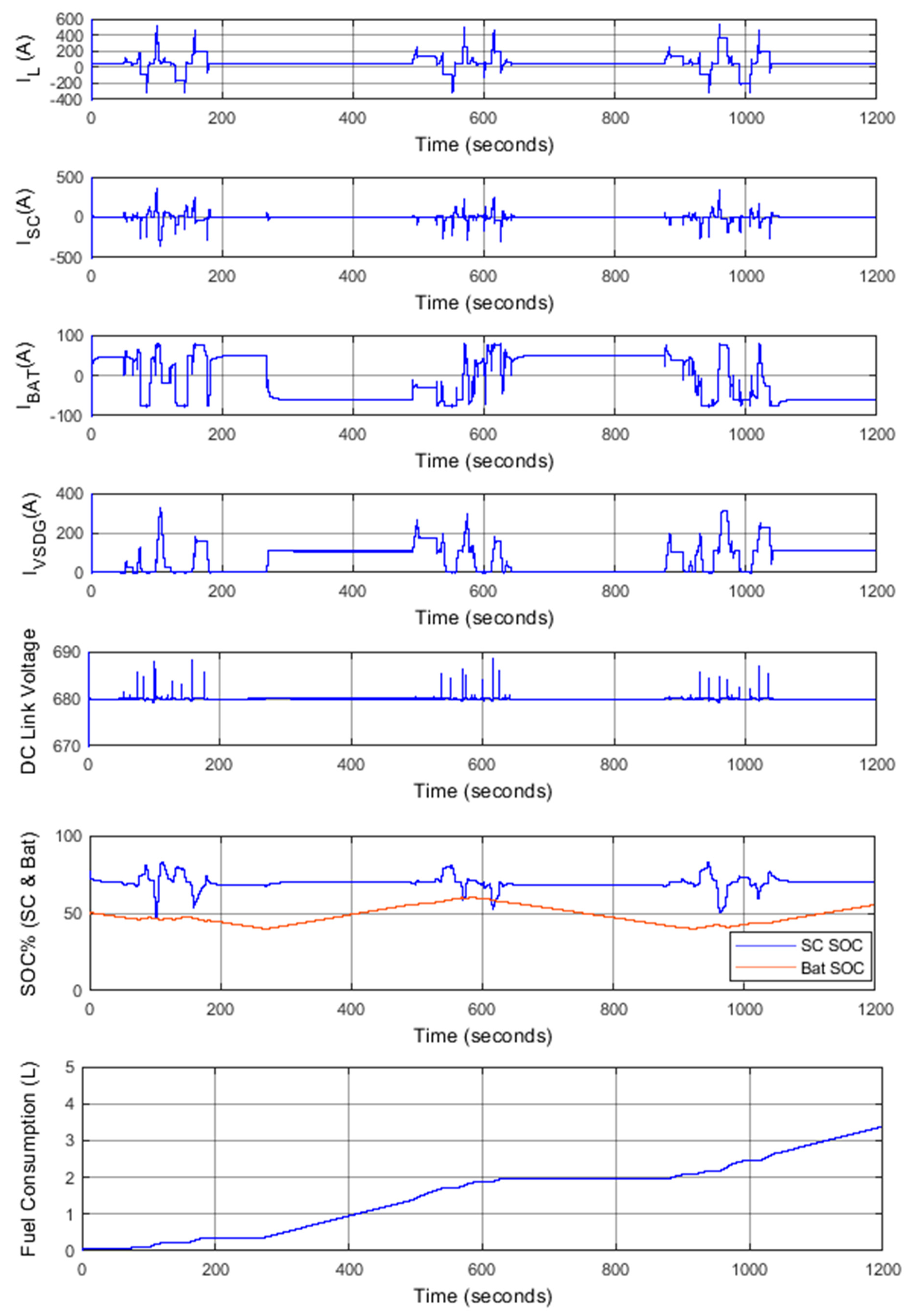
C. Case 3: Simulation with an initial battery SOC of 50% with quite operation
This case was simulated with an initial battery SOC of 50%, so that battery starts to work with a normal SOC, in which both the charging and discharging of the battery are allowed. Figure 14 shows the SOC variations and current variations of energy sources. During 20 min period, two discharge and charge cycles can be seen from the battery SOC graph. Battery current variations were low compared to Case 2, due to higher idling period as in Case 1. System operates as expected within defined boundaries.
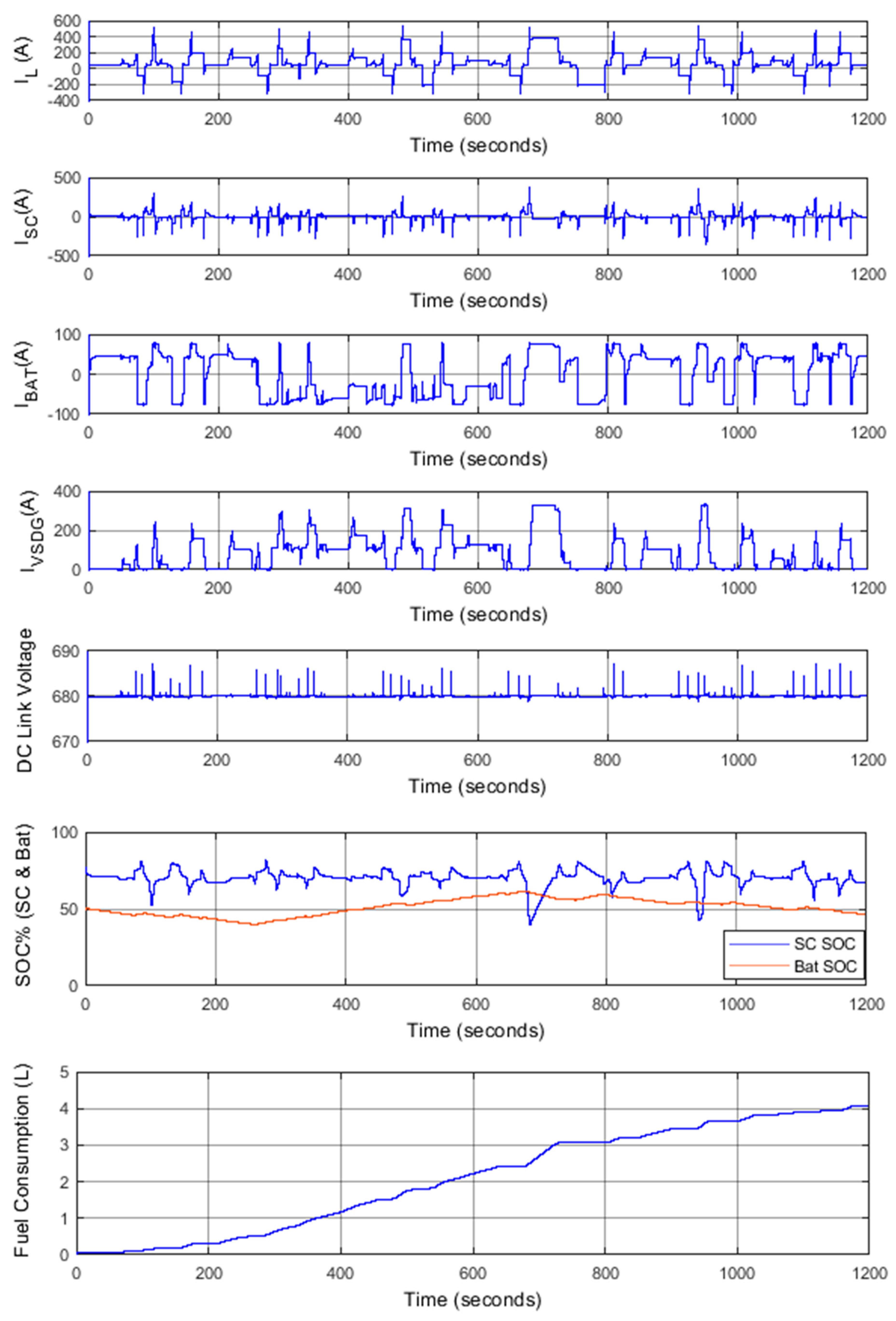
D. Case 4: Simulation with an initial battery SOC of 50% with busy operation
This case was simulated with an initial battery SOC of 50% with busy power profile. At initial point of start, battery discharging, and charging are allowed. Figure 15 shows the SOC variations and current variations. Maximum peak demand of VSDG, 330 A had been recorded during the operating period of the highest energy demanding move. Large SOC variations of SC can be seen similar to Case 2, which had taken much longer time to recover. During the simulation period, all important parameters such as SC SOC, DC bus voltage, battery current and VSDG current had not violated their designed rules.
E. Discussion
The proposed configuration for the hybrid system and the EMS safely operates with a 200 kW VSDG which is downsized by 50% compared to conventional generator capacity. The simultaneous operation of VSDG, SCs and battery have potential to supply total demand including 500 A current peaks. Lower generator capacity and its variable speed operation are the main dominant factors for fuel saving. Instead of using conventional constant speed 400 kW generator, proposed system uses 200 kW variable speed genset. During simulations, 50 A/s rate of increase was introduced to simulate the low dynamic response of VSDG. Throughout the time of operation on 4 cases, system did not progress to any unstable conditions. High SC SOC distortions can be seen in Case 2 and Case 4 where average power requirement is at its highest value. Lower SOC valleys of SC had taken considerable time to recover due to high power demand (above 350 A) by the container move. The VSDG loading, fuel consumption and fuel consumption per move are presented on Table 3.
The battery SOC transition cycles represent the complete transitions that Li-ion battery had undergone either charging from 40% to 60% or discharging 60% to 40%. The Case 1 and Case 3 have recorded 3 transitions in quiet operating condition due to pure electric mode operation to supply auxiliary power during crane idle period. A considerable deviation between fuel consumption per move can be seen in quite (Case 1 and Case 3) and busy (Case 2 and Case 4) conditions due to low generator loading above 150 kW margin which can be clearly visible on “VSDG loading more than 150 kW” column in Table 3. During all 4 operating cases, VSDG had maintained a load above 50 kW for more than 75% of its active time.
The results demonstrate that the proposed hybrid system and EMS allow the RTGC to properly follow the driving cycle. In this paper, we have obtained good results for the RTGC following its operating cycle. Using three power sources namely VSDG, SC bank and battery connected to DC bus via AC/DC and DC/DC converters enable the EMS to actively control the power flow and achieve stable system which can operate continuously.
6. Conclusions
In this study, a new energy management strategy combined with a hybrid energy supply system (HESS) was investigated. The main purpose of this new strategy is to reduce the risks associated with battery life in the HESS while supplying the demand in the DC bus. The HESS is comprised of a variable speed diesel generator, supercapacitor bank, and Li-ion battery bank. the new energy management strategy controls the battery SOC in a narrow band while maintaining the battery SOC on a fixed level of 70%. Based on the DC bus current and previous operating state, the controller chooses the next operating state and calculate the necessary current points for VSDG converter, Li-ion battery DC/DC converter and braking chopper.
The performance of battery-based hybrid RTGC was improved using the proposed HESS and energy management strategy. Simulations of proposed configuration and the state control machine were performed in the Matlab/Simulink simulation environment. The simulation results shows that the proposed HESS and EMS could satisfy the power and energy demands of the DC bus while controlling battery SOC under a narrow band which reduce the probability of reaching deep discharge and overcharge. The current levels in the battery bank and VSDG were maintained within the specified limits. The results have demonstrated the capability of meeting appropriate driving cycle with an increased fuel savings up to 57.5% compared to conventional RTGC with the proposed energy management system.
Author Contributions
All authors contributed to the present paper with the same effort in finding available literature resources, conducting both simulations and measurements, as well as writing the paper.
Funding
This work was supported by University of Moratuwa Senate Research Committee Grant SRC/CAP/2018/03.
Acknowledgments
The authors would like to thank for terminal operators inside port of Colombo for supporting with energy consumption and fuel consumption data.
Conflicts of Interest
The authors declare no conflict of interest.
Appendix A

Table A1.
Model parameters of proposed hybrid system.
| Parameter | VSDG | Supercapacitor | Battery |
|---|---|---|---|
| Rated current (A) | 300 | 100 | 40 |
| Max current on DC bus (A) | 330 | 500 | 75 |
| Dynamic current response | 50 A/s | 700 us for full load | 100 A/s |
| Supercapacitor SOC control level | - | 70% | - |
| Minimum SC SOC level | - | 25% | - |
| Li-ion battery lower SOC margin | - | - | 40% |
| Li-ion battery top SOC margin | - | - | 60% |
| Control mode | CCM | CV | CCM |
| Capacity | 350 kVA | 48.3 F | 40 Ah |
| Rated source voltage (V) | 600 | 334 | 372 |
| DC/DC converter capacity | 250 kW | 250 kW | 60 kW |
| DC/DC converter topology | 3 leg interleaved DC/DC converters | ||
| DC/DC converter minimum operating voltage (V) | 100 V | 100 V | 100 V |
| DC bus voltage (V) | 680 V | ||
References
- OPEC: Annual Statistical Bulletin. Available online: http://www.opec.org/opec_web/en/publications/202.htm (accessed on 25 October 2018).
- Flynn, M.M.; McMullen, P.; Solis, O. Saving energy using flywheels. IEEE Ind. Appl. Mag. 2007, 14, 69–76. [Google Scholar] [CrossRef]
- Kim, S.M.; Sul, S.K. Control of rubber tire gantry crane with energy storage based on supercapacitor bank. IEEE Trans. Power Electron. 2006, 21, 1420–1427. [Google Scholar] [CrossRef]
- Sybrid System, Hybrid Technology for Rubber tire Gantry Cranes. Available online: http://www.shi.co.jp/shi-mh/english/technical/sybrid.html (accessed on 19 November 2018).
- Mulder, S. Energy Management System Hybrid Container Crane; Delft University of Technology: Delft, The Netherlands, 2009. [Google Scholar]
- Hellendoorn, H.; Mulder, S.; Schutter, B.D. Hybrid Control of Container Cranes. In Proceedings of the 18th IFAC World Congress, Milan, Italy, 28 August–2 September 2011; pp. 9697–9702. [Google Scholar]
- Case Study: Hybrid Rubber Tired Gantry Cranes, Corvus Energy. Available online: https://corvusenergy.com/port-equipment/ (accessed on 19 November 2018).
- Bolonne, S.R.A.; Chandima, D.P. Modeling and Simulation of an Electromechanical System for a Hybrid Rubber Tire Gantry Crane. In Proceedings of the 2nd International Conference on Electrical Engineering, Colombo, Sri Lanka, 28 September 2018; pp. 14–20. [Google Scholar]
- CMinnotech. Explore Exchanges for Further Upgrade Transformation Technical solutions of CICT E-RTG. Unpublished work. February 2017. [Google Scholar]
- RTG-VSG Hybrid Power Supply System-Operational Manual; Shenzhen Jingnengfang and System Integration Co., LTD: Shenzhen, China, 2012.
- Lithium Ion Battery for Industrial Use; GS YUASA International Ltd.: Tokyo, Japan.
- Simpowersystem Blocks, Battery. Available online: https://in.mathworks.com/help/physmod/sps/powersys/ref/battery.html?searchHighlight=Battery&s_tid=doc_srchtitle (accessed on 7 November 2018).
- Omar, N.; Monem, M.A.; Firouz, Y.; Salminen, J.; Smekens, J.; Hegazy, O.; Gaulous, H.; Mulder, G.; Bossche, P.V.D.; Coosemans, T.; et al. Lithium iron phosphate-based battery—Assessment of aging parameters and development of cycle life model. Appl. Energy 2014, 133, 1575–1585. [Google Scholar] [CrossRef]
- Saw, L.H.; Somasundaram, K.; Ye, Y.; Tay, A.A.O. Electro-thermal analysis of Lithium Iron Phosphate battery for electric vehicles. J. Power Sources 2014, 249, 231–238. [Google Scholar] [CrossRef]
- Zhu, C.; Li, X.; Song, L.; Xiang, L. Development of a theoretically based thermal model for Lithium ion battery pack. J. Power Sources 2013, 223, 155–164. [Google Scholar] [CrossRef]
- Tremblay, O.; Dessaint, L.A. Experimental validation of a Battery Dynamic Model for EV applications. World Electr. Veh. J. 2009, 3, 289–298. [Google Scholar] [CrossRef]
- Datasheet K2 Ultracapacitors—3.0V/3000F; Maxwell Technologies Inc.: San Diego, CA, USA, 2016.
- Simpowersystem Blocks, Supercapacitor. Available online: https://in.mathworks.com/help/physmod/sps/powersys/ref/supercapacitor.html (accessed on 3 November 2018).
- Oldham, K.B. A Gouy-Chapman Stern model of the double layer at a (metal)/(ionic liquid) interface. J. Electroanal. Chem. 2007, 613, 131–138. [Google Scholar] [CrossRef]
- Gracia, P.; Torreglosa, J.P.; Fernandez, L.M.; Jurado, F. Viability study of a FC-battery-SC tramway controlled by equivalent consumption minimization strategy. Int. J. Hydrogen Energy 2012, 37, 9368–9382. [Google Scholar] [CrossRef]
- Rubber-Tired Gantry Crane for Sri Lanka Project-Mechanical Calculation; Shanghai Zhenhua Heavy Industry Co., Ltd.: Shanghai, China, 2008.
- One Rubber-Tired Gantry Container Crane for Port Hambantota-Mechanical Calculation; Shanghai Zhenhua Heavy Industry Co., Ltd.: Shanghai, China, 2014.
- Thiyagarajan, A.; Kumar, S.G.P.; Nandini, A. Analysis and comparison of conventional and interleaved DC/DC boost converter. In Proceedings of the Second International Conference on Current Trends in Engineering and Technology—ICCTET 2014, Coimbatore, India, 8 July 2014; pp. 198–205. [Google Scholar]
- DC/DC Converter Operating Guide; Vacon: Uusimaa, Finland, 2016.
- SINAMICS DCP 120 kW; Siemens Industry, Inc.: Norcross, GA, USA, 2016.
- Simpowersystem Blocks, Two-Quadrant dc/dc Converter. Available online: https://in.mathworks.com/help/physmod/sps/examples/two-quadrant-dc-dc-converter.html (accessed on 15 November 2018).
- Hussein, A.A. Capacity fade estimation in electric vehicles Li-ion batteries using artificial neural networks. IEEE Trans. Ind. Appl. 2015, 51, 2321–2330. [Google Scholar] [CrossRef]
- Savoye, F.; Venet, P.; Millet, M.; Groot, J. Impact of Periodic Current Pulses on Li-Ion Battery Performance. IEEE Trans. Ind. Electron. 2012, 59, 3481–3488. [Google Scholar] [CrossRef]
- Shafiei, N.; Ordonez, M.; Craciun, M.; Botting, C.; Edington, M. Burst Mode Elimination in High-Power LLC Resonant Battery Charger for Electric Vehicles. IEEE Trans. Power Electron. 2016, 31, 1173–1188. [Google Scholar] [CrossRef]
- Hannan, M.A.; Hoque, M.M.; Hussain, A.; Yusof, Y.; Ker, P.J. State-of-the-Art and Energy Management System of Lithium-Ion Batteries in Electric Vehicle Applications: Issues and Recommendations. Adv. Energy Storage Technol. Their Appl. 2018, 6, 19362–19378. [Google Scholar] [CrossRef]
- Joon, H.L.; Seung, H.L.; Seung, K.S. Variable-Speed Engine Generator with Supercapacitor: Isolated Power Generation System and Fuel Efficiency. IEEE Trans. Ind. Appl. 2009, 45, 2130–2135. [Google Scholar] [CrossRef]
- New Liebherr Energy Storage System Liduro Increases Productivity of Electric Drive Systems. Available online: https://www.liebherr.com/en/int/latest-news/news-press-releases/detail/new-liebherr-energy-storage-system-liduro-increases-productivity-of-electric-drive-systems.html (accessed on 4 December 2018).
Figure 1.
Directions of motions of rubber tire gantry crane (RTGC) (1-Trolley, 2-Hoist, 3-Gantry).

Figure 2.
(a) Quite power profile; (b) Busy power profile.


Figure 3.
Configuration of proposed hybrid RTGC model. DG: diesel generator; SC: supercapacitor bank.
Figure 3.
Configuration of proposed hybrid RTGC model. DG: diesel generator; SC: supercapacitor bank.

Figure 4.
Discharge characteristics of LIM40-7D cell ( Reproduced courtesy of the GS Yuasa) [11].
Figure 4.
Discharge characteristics of LIM40-7D cell ( Reproduced courtesy of the GS Yuasa) [11].

Figure 5.
Discharge characteristics of proposed cell model.

Figure 6.
Charging characteristics of 3.0 V/3000 F SC cell of the proposed model [17].
Figure 6.
Charging characteristics of 3.0 V/3000 F SC cell of the proposed model [17].

Figure 7.
Specific fuel consumption of proposed VSDG.

Figure 8.
Average-value model of DC/DC converter.

Figure 9.
VSDG architecture.

Figure 10.
State Machine Controller.

Figure 11.
SC Charge controller.

Figure 12.
SOC and current variations of Case 1.

Figure 13.
SOC and current variations of Case 2.

Figure 14.
SOC and current variations of Case 3.

Figure 15.
SOC and current variations of Case 4.

Table 1.
Crane specifications.
| Parameter | Configuration/Setting |
|---|---|
| Gantry span | 6 wide + truck lane |
| Lifting heights | 1 over 6 |
| Lifting capacity | 40 t |
| Hoist speed | 0.433 m/s with rated load 0.866 m/s with empty spreader |
| Hoist acceleration | 2 s, rated load 4.5 s, empty spreader |
| Hoist deceleration | 2 s, rated load 4.5 s, empty spreader |
| Trolley travel speed | 1.666 m/s |
| Trolley acceleration and deceleration | 4 s |
s = second, min = minute, m = meter, t = metric ton.
Table 2.
Hybrid System Specifications.
| Parameter | VSDG | SC | Battery |
|---|---|---|---|
| Rated Current (A) | 300 | 100 | 40 |
| Max Current (A) | 330 | 500 | 150 |
| Current slew rate (A/s) | 50 | - | 100 |
| SOC (min) | - | 70% | 40% |
| SOC (max) | - | 25% | 60% |
| Control mode(CCM, CV) | CCM | CVM | CCM |
| Capacity | 350 kVA | 48.3 F | 40 Ah |
| Rated voltage (V) | 600 | 334 | 372 |
| DC bus voltage (V) | 680 | ||
CCM—Controlled current mode, CVM—Constant voltage mode.
Table 3.
Diesel consumption and generator loading.
| Case | Fuel Consumption (L) | Fuel Consumption Per Move (L/move) | Battery SOC Transition Cycles | VSDG Loaded Time (s) (Active Time) | VSDG Loading More Than | ||
|---|---|---|---|---|---|---|---|
| 50 kW (s) | 100 kW (s) | 150 kW (s) | |||||
| Case 1 | 3.66 | 1.22 | 3 | 719.5 | 666.1 | 114.3 | 55.6 |
| Case 2 | 4.3 | 0.71 | 2 | 772.8 | 602.2 | 247.7 | 130.1 |
| Case 3 | 3.38 | 1.13 | 3 | 674.7 | 607 | 120.4 | 37.6 |
| Case 4 | 4.06 | 0.67 | 2 | 716.7 | 573.7 | 231.3 | 107.6 |
© 2019 by the authors. Licensee MDPI, Basel, Switzerland. This article is an open access article distributed under the terms and conditions of the Creative Commons Attribution (CC BY) license (http://creativecommons.org/licenses/by/4.0/).
Share and Cite
MDPI and ACS Style
Bolonne, S.R.A.; Chandima, D.P. Narrow Band State of Charge (SOC) Control Strategy for Hybrid Container Cranes. Energies 2019, 12, 743. https://0-doi-org.brum.beds.ac.uk/10.3390/en12040743
AMA Style
Bolonne SRA, Chandima DP. Narrow Band State of Charge (SOC) Control Strategy for Hybrid Container Cranes. Energies. 2019; 12(4):743. https://0-doi-org.brum.beds.ac.uk/10.3390/en12040743
Chicago/Turabian StyleBolonne, Sheron Ruchiranga Anton, and Dedduwa Pathiranage Chandima. 2019. "Narrow Band State of Charge (SOC) Control Strategy for Hybrid Container Cranes" Energies 12, no. 4: 743. https://0-doi-org.brum.beds.ac.uk/10.3390/en12040743
Note that from the first issue of 2016, this journal uses article numbers instead of page numbers. See further details here.