Study on the Thermal Performance of a Hybrid Heat Collecting Facade Used for Passive Solar Buildings in Cold Region


1
Architecture and Urban Planning College, Southwest Minzu University, Chengdu 610041, China
2
School of Mechanical Engineering, Southwest Jiaotong University, Chengdu 610031, China
*
Author to whom correspondence should be addressed.
Energies 2019, 12(6), 1038; https://0-doi-org.brum.beds.ac.uk/10.3390/en12061038
Submission received: 25 January 2019
/
Revised: 4 March 2019
/
Accepted: 12 March 2019
/
Published: 18 March 2019
(This article belongs to the Special Issue Building Thermal Envelope)
Abstract
:Passive solar technologies are traditionally considered as cost-effective ways for the building heating. However, conventional passive solar buildings are insufficient to create a relatively stable and comfortable indoor thermal environment. To further increase the indoor air temperature and reduce the heating energy consumption, a hybrid heat collecting facade (HHCF) is proposed in this paper. To analyze the thermal performance of the HHCF, a heat transfer model based on the heat balance method is established and validated by experimental results. Meanwhile, the energy saving potential of a room with the HHCF is evaluated as well. When the HHCF is applied to places where heating is required in the cold season while refrigeration is unnecessary in hot season, the HHCF can reduce the heating need by 40.2% and 21.5% compared with the conventional direct solar heat gain window and the Trombe wall, respectively. Furthermore, a series of parametric analyses are performed to investigate the thermal performance of the room with HHCF under various design and operating conditions. It is found that the thermal performance of the HHCF mainly depends on the window operational schedule, the width and the absorptivity of heat collecting wall, and the thermal performance of the inner double-glass window. The modeling and the parametric study in this paper are beneficial to the design and the optimization of the HHCF in passive solar buildings.
1. Introduction
Passive solar building is a type of low-energy buildings exploiting solar energy to create a relatively comfortable environment in buildings [1,2]. Thermal energy collection and storage in building envelops may be enhanced by integrating some passive solar measures [3,4,5,6,7]. It was reported by measurements that passive solar buildings can save more than 25% of total primary energy consumption than the same buildings without passive solar measures [8,9,10]. As two efficient technologies used in passive solar houses, direct solar heat gain window and thermal storage wall (e.g., Trombe wall) are widely used [11]. For the direct solar heat gain window, sunlight passes through the window and enters into the indoor space, solar energy is absorbed in the floor or the interior wall during the daytime due to the effect of thermal mass. Then the stored thermal energy is gradually released into the indoor space when the room temperature falls down at night. While for the thermal storage wall, solar energy is initially absorbed and stored by the heat collecting wall (such as the exterior wall) in the daytime, rather than directly coming into the room. The thermal energy stored in the heat collecting wall is released at night to improve the indoor temperature as well. Both of these two methods are beneficial to improve the thermal performance of the passive solar building in the cold region [12].
In fact, due to the high U-value of the window, the direct solar heat gain strategy is more easily influenced by the outdoor temperature. Meanwhile, the indoor air temperature fluctuation of the direct solar heat gain room is relatively large [13], which limits the further improvement of the indoor thermal performance. The Trombe wall not only collects and stores solar energy for the indoor heating, but also reduces the heat loss from the indoor to the outdoor environment due to the outside glass cover [14]. Meanwhile, for a specific facade, the larger area of the Trombe wall decreases the maximum window to wall ratio, resulting in less solar energy coming into the indoor space [15,16]. Based on the above descriptions, if the direct solar heat gain window and the Trombe wall are combined well with each other in the practical application, the thermal performance of the passive solar building can be further improved. Therefore, we developed a hybrid passive solar energy utilization form, named hybrid heat collecting façade (HHCF).
Although there are very few directly related studies about the HHCF, plenty of investigations about the thermal performance of passive solar houses with the direct solar gain window [17,18,19,20,21,22] or the thermal storage wall [23,24,25,26] could provide effective research techniques for analyzing the thermal performance of the HHCF. Through literature research, it can be found that experiments and numerical simulations are two widely used methods. Based on experiments and simulations, researchers have shown that the direct solar heat gain strategy is quite effective to improve the indoor thermal performance [27,28,29,30]. For instance, numerical simulations have been carried out by Gong et al. [31] and it was found that the direct solar heat gain house could significantly reduce the annual thermal load of the building. A study conducted by M.C. Ruiz [32] also showed that the overall thermal consumption of a building was reduced by almost 13% through optimizing the building direction, the window–wall ratio, and the insulation of the direct solar heat gain building. These analytical methods are helpful for carrying out the thermal performance of the HHCF.
In this paper a novel hybrid heat collecting façade (HHCF) is proposed, integrating the advantages of both the direct solar heat gain window and the traditional Trombe wall. A heat transfer simulation model is developed for analyzing the thermal performance of the building with the proposed HHCF. Experiments are conducted to validate the accuracy of the heat transfer model. Meanwhile, in order to explore the energy saving potential of the HHCF, the thermal performance of a building with the HHCF is compared with those of a conventional building with the direct solar heat gain and with the Trombe wall, respectively. During the comparison, the numerical simulation method is adopted and the cell buildings are with the same geometry except for the solar system. In addition, a parametric study is employed to analyze the influences of various factors on the thermal performance of the HHCF. With the model established in this paper, the thermal performance of the building with the HHCF can be analyzed and optimized, which will provide a simulation tool for designing the HHCF in regions where heating is required in the cold season while refrigeration is unnecessary in hot season.
2. Materials and Methods
2.1. Principle of HHCF
Previous studies have shown that the direct solar heat gain window and the thermal storage wall are effective to improve the indoor thermal performance. However, the application of the direct solar heat gain window is liable to decrease the indoor temperature at night, since the high U value of the window largely increases the heat loss from the indoor space to the outdoor environment. The Trombe wall is opaque and prevents the sunlight into the indoor space. Thus, in order to ensure the necessary daylight for the building with the Trombe wall, a transparent window is dispensable but it leads to the extra heat loss from the room to the outside environment. To solve this problem, a novel hybrid heat collecting facade is proposed in this paper.
The schematic diagram of the HHCF is shown in Figure 1. The HHCF is normally mounted on the south wall, and mainly consists of a single-glass window, a double-glass window, and a heat collecting wall. In the HHCF, there are two functional spaces including the heat collecting space and the heat transfer space. The heat collecting space is surrounded by the single-glass window and the heat collecting wall, which behaves as the “Trombe Wall” and can be used to convert solar energy into thermal energy for heating the air. The heat transfer space is surrounded by the single-glass window and the double-glass window. Since the double-glass window can be opened and closed acting as a door, the heat transfer space allows the solar energy to directly transmit into the indoor space, as well as increasing the thermal resistance between the indoor space and the outdoor environment. For indoor heat exhaust ventilation and to prevent indoor overheating that may occur in the hot season, a transparent window is inlaid in the upper part of the single glass window and it can be opened and closed. In this paper, we mainly focus on places where heating is required in the cold season while refrigeration is unnecessary in the hot season and for this situation the inlaid window is closed.
The operation principle of the HHCF can be seen in Figure 1:
- In a sunny day, solar energy is absorbed by the exterior surface of the heat collecting wall and converted into thermal energy for heating the air convectively within the heat collecting space. With the inner double-glass window open, the heated air in the heat collecting space rises up and reaches the top of the heat collecting space under the effect of the buoyancy force. Then, the heated air gathers at the top of the heat collecting space and increases the air pressure at the top of the heat collecting space. Finally, under the effect of the pressure difference, the heated air passes through the heat transfer space and enters into the indoor space along the horizontal direction. Meanwhile, at the bottom of the heat collecting space, the low-pressure cavity is supplied by the indoor air along the horizontal direction. In this way, thermal energy is transferred into the room space and the indoor temperature rises. Moreover, sunlight can also penetrate the windows into the indoor space directly and the solar energy is stored in the interior building construction.
- At night or during a cloudy day, the inner double-glass window should be kept closed, and it increases the thermal resistance between the indoor space and the outdoor environment. Consequently, the heat loss from the indoor space to the outdoor environment can be effectively reduced, especially at night.
2.2. Modeling of the Building with HHCF
To evaluate the thermal performance of the building with HHCF, the simulation model is established in this section and necessary assumptions are made for simplifying the simulation.
2.2.1. Assumptions
For simplifying the analysis, the following assumptions are made:
- (1)
- Thermal properties of the building materials are kept constant.
- (2)
- Heat transfer processes through walls, floor, roof, and windows are considered as one-dimensional.
- (3)
- The heat storage of glass is ignored.
- (4)
- Air in each zone is well-mixed.
- (5)
- Mean air flow rate between the heat collecting space and the heat transfer space is identical with that between the heat transfer space and the indoor space.
2.2.2. Energy Balance Equations
For solving the heat transfer processes of a building with HHCF, energy balance equations for HHCF, indoor air and building constructions have been established as displayed in Figure 2.
● Heat transfer of HHCF
Heat transfer of HHCF can be considered as two heat processes as shown in Figure 2: (1) heat transfer in the heat collecting space and (2) heat transfer in the heat transfer space. Heat balance equations are established for these two spaces of the HHCF.
(1) For the heat collecting space,
In Equation (1), is the convective heat transfer rate from the heat collecting wall to the air in the gap. is the heat transmission rate from the outdoor to the heat collecting space through the single-glass window, which considers the effect of the heat conduction of the single-glass window and the heat convection of both the interior surface and the exterior surface of the single-glass window. is the convective heat transfer rate from the heat collecting space to the heat transfer space. , , can be obtained by the following equations:
The mean air flow rate between the heat collecting space and the heat transfer space (or between the heat transfer space and the indoor space) is obtained by Bernoulli’s equation [33], as given in Equation (5).
where the term represents the pressure loss of the heat collecting space. The ratio indicates the difference between the air velocity in the vents and the air velocity in the air gap.
(2) For the heat transfer space,
where is the heat transfer rate from the outdoor to the heat transfer space passing through the single-glass window.
is the convective heat transfer rate from the heat transfer space to the indoor space passing through each open double-glass window, is the conductive heat transfer rate from the heat transfer space to the indoor space through the closed double-glass window.
(a) When the double-glass window is closed, , can be expressed as
(b) When the double-glass window is open, , can be expressed as
where .
● Heat transfer of building construction
For the building construction, the heat transfer schematic is illustrated in Figure 3 and the implicit finite difference technique is employed to model the heat transfer process of building envelopes by solving the one dimensional transient heat conduction equation [34]:
Subjected to the boundary conditions:
where is the total thermal radiation heat flux from the outdoor. For example, the exterior surface of the heat collecting wall is heated by the solar energy, and the solar radiation heat flux can be calculated by
For general building constructions, could be expressed as
represents the long-wave radiation exchange from surrounding surfaces. The gray interchange model is used to calculate the thermal radiation heat exchange between interior surfaces. Meanwhile, the radiosity concept developed by Hottel and Sarofim is adopted [35]. The net radiative heat transfer at a surface can be determined by Equation (17).
where the radiosity, , represents the sum of the gray body radiation of temperature and the incident radiation, and it can be expressed as Equation (18).
The incident radiation, , is normally unknown. If a certain surface is hit by radiation from another surface , the radiation heat energy incident on surface [36] can be described as Equation (19).
where is the view factor from surface to .
is the transmitted solar radiation through the fenestration absorbed by the interior surface. In this model, a simplified interior solar distribution model developed by Benjamin and Moncef Krarti [37] is employed to calculate the transmitted solar radiation absorbed by the floor and other interior surfaces, respectively.
The transmitted solar radiation absorbed by the floor can be expressed as
The transmitted solar radiation absorbed by other interior surfaces excluding the floor can be expressed as
where is the transmitted solar radiation through the window.
Convective heat transfer coefficients of the exterior surface and the interior surface of the building construction can be calculated by the following equations [38]:
where is the temperature difference between the air and the construction surface. is the outside average wind velocity.
● Heat balance of indoor air
The indoor air heat balance model establishes the interaction among walls, the indoor air and the hybrid heat collecting facade, which can be written as
where is the convective heat transfer rate from the interior surface of the building construction to the indoor air, is the heat transfer rate through other windows excluding the HHCF, is the heat transfer rate by air leakage, is the heat transfer rate from indoor heat sources including lighting, occupants, and equipment. , , and are calculated by the following equations:
where is the interior surface temperature of the wall, the ceiling or the floor, is the interior surface area, is the air change rate of the room, and are the heat transfer coefficient and the area of the window, respectively.
Figure 4 gives the heat transfer mechanisms and solving methods for various surfaces and spaces. In the developed model, the implicit finite difference method (FDM) is adopted to calculate the hourly thermal performance of the room with the HHCF [39]. The heat balance equations established for the HHCF, building constructions and the indoor air are converted into algebraic equations using the central difference scheme. To reduce the consumption of computational memory and the computational time, the Gauss-Seidel iteration method is adopted to calculate the indoor air temperature and surface temperatures as described in the reference [38]. It should be noted that for calculating the dynamic heating load of the building, the indoor air temperature will be fixed to the set-point temperature in the procedure.
2.2.3. Validation of Heat Transfer Model
Experiments are employed to validate the simulation model established in this paper. Figure 5 shows a 3-storey dormitory building with a HHCF in Ruoergai, China. In order to reduce the influence of outdoor conditions and the ground on the indoor air temperature, the middle room on the second floor of the building marked in Figure 5 was selected as the experimental room. Figure 6 shows the geometry of the test room, with the dimensions of 3.3 m (width) × 6.4 m (depth) × 3.0 m (height). The HHCF faces south, where two heat collecting walls with a width of 0.5 m and one double-glass window with a width of 2.3 m are located. The percentage of double-glass window area compared to the whole wall area is 69.7%. One door faces north with the size of 2.0 m (height) × 1.0 m (width). Detailed constructions of the room and thermal properties of the material are listed in Table 1.
For the validation of the heat transfer model established above, indoor air temperature of the test room, air temperature of the heat transfer space, and interior surface temperature of the west interior wall were measured with the double-glass window open and closed. Meanwhile, environmental parameters including outdoor temperature, solar radiation intensity, and outdoor wind speed were also recorded for the input data in the simulation model. In addition, exterior surface temperatures of five interior constructions (three interior walls, the floor, and the ceiling) contacting with adjacent rooms were monitored, which would be used as boundary conditions in the simulation model.
Experiments were performed from 27 March to 2 April 2016. During the experimental period, the door was closed all the time, while the double-glass window was closed during the first five days and in the last two days it was open at 9:00–17:00 for each day. In the test room, no other space heating system is considered, and there is no internal heat gain from the lighting, occupants, and equipment.
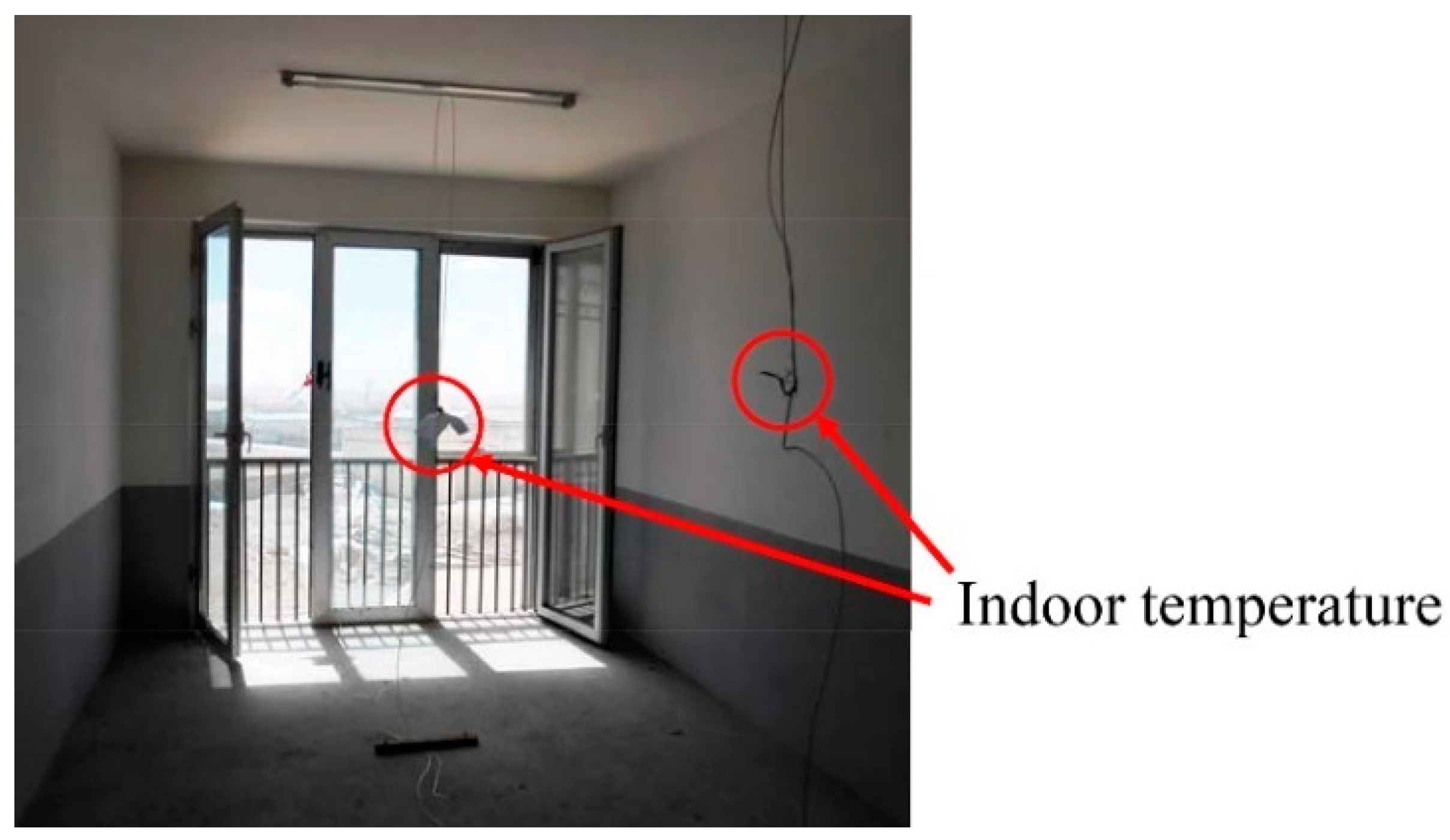
To conduct the experimental test, thermocouples were used to monitor the indoor air temperature and various surface temperatures as seen in Figure 7. While outdoor temperature, solar radiation intensity and outdoor wind speed were measured by a small weather station as shown in Figure 8. The K-T method proposed by Klien and Theilacker [40] was adopted to convert the measured horizontal solar radiation into the incident solar radiation on the south wall.
In the transient simulation, the initial thermal inertia and initial conditions of the building have significant influences on the simulated results. In order to eliminate these influences, the monitored experimental data of the first three days are used for making the simulation stable and test results for the last four days are validated against results from the simulation. Figure 9 gives the comparative analysis of results of the test room obtained from the experimental test and the simulation. Comparing the mean indoor air temperature (Figure 9a), the air temperature of the heat transfer space (Figure 9b), and the interior surface temperature of the west wall (Figure 9c) under two different conditions (with double-glass window closed all the time and with it open at 9:00–17:00), it can be seen that the simulated results agree quite well with the experimental results under both conditions, which means the heat balance model established in this paper is enough accurate for evaluating the thermal performance of building with HHCF.
2.2.4. Energy Saving Comparison of HHCF
In order to illustrate the energy saving potential of the proposed HHCF, the thermal performances of the above studied dormitory room using the HHCF and using other typical passive solar measures are compared. All the physical dimensions and thermal properties of building materials are the same as the experimental room except the passive solar design on the south wall. This typical room is assumed to be located in Ruoergai of China and the weather data are obtained from the typical year weather data of China based on the past 30 years’ climate data [41].
Three cases used in the comparison are illustrated in Figure 10. Case 1 is the room with the direct solar heat gain window. In this case the sunlight directly passes through the window and enters into the indoor space to improve the thermal performance of the room. Case 2 is the room with the traditional Trombe wall. The heated air in the Trombe wall rises up with the effect of buoyancy effect and enters into the indoor space through the hole at the top, while the indoor air is sucked into the Trombe wall through the hole at the bottom. Case 3 is the room with the proposed HHCF in this paper.
For Case 3, the design of the HHCF is the same with the test room. In Cases 1 and 2, the direct solar heat gain window is the same with the double-glass window used in the HHCF, and the percentage of the direct solar heat gain window area compared to the exterior wall area is 69.7%. Unlike Case 1, the Trombe wall in Case 2 is installed on both sides of the south wall, each side with a width of 0.5 m. For the Trombe wall, the inlet and the outlet have the same dimensions of 0.25 m (width) × 0.15 m (height).
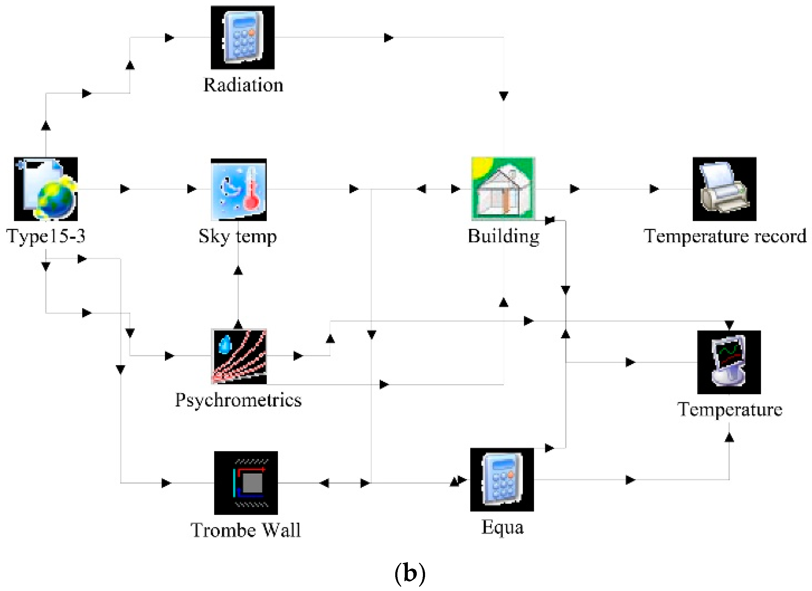
In order to compare the thermal performance of these three cases, both the indoor air temperature and the heating need of those cases are compared. It should be noted that Case 3 is investigated with the proposed simulation model and the other cases are simulated by TRNSYS [42]. The TRNSYS model for Cases 1 and 2 are shown in Figure 11a,b, respectively. In Figure 11a, Type56 building model is used to simulate the direct solar heat gain window. In Figure 11b, Type36 and Type56 are used to separately simulate the Trombe wall and the building. Meanwhile, only the heating season is considered and the heating season is from November 1st to March 31st of the next year. The heating schedule is from 18:00 to 8:00 of the next day during weekdays (from Monday to Friday) and the heating set-point temperature is 18.0 °C. While during the daytime of weekdays (from 8:00 to 18:00) and the weekend, no heating system runs and the indoor thermal performance largely depends on the passive solar measures such as the direct solar heat gain window, the Trombe wall and the HHCF.
3. Results and Discussion
3.1. Energy Saving Potential of HHCF
Figure 12 shows the indoor air temperature and the heating need on the heating design day (21 January) predicted by the simulations. As seen in Figure 12, the studied room with the proposed HHCF (Case 3) has a higher temperature and a lower heating need than the other two passive measures (Cases 1 and 2). Table 2 summarizes the indoor air temperature and the total heating need of the studied room during the heating season. As shown in Table 2, during the heating season, the mean indoor air temperature for the studied room with the proposed HHCF is 18.6 °C, which is 1.1 °C and 0.4 °C higher than those of the direct solar heat gain window and the Trombe wall, respectively. Meanwhile, the total heating need of the studied room with the proposed HHCF in the heating season is 28.7 kWh/m2. Compared with the conventional direct solar gain window, the HHCF reduces the total heating need of the room by 19.2 kWh/m2 and the energy-saving efficiency reaches 40.2%. Even in contrast to the conventional Trombe wall, the HHCF also decreases the total heating need by 21.5%. The comparison results show that the HHCF proposed in this paper has very high energy saving potential.
3.2. Parametric Study on the Thermal Performance of a Room with a HHCF
In order to analyze the thermal performance of the HHCF in a passive solar building, the dormitory located in Ruoergai as mentioned in Section 3 is still used as the simulated case. The weather data used in simulations are obtained from the typical year weather data of China [41]. Similarly, no other space heating system is considered in this building, and the internal heat gain from the lighting, occupants, and equipment are neglected.
The thermal performance of a room with a HHCF facing south is influenced by various factors, such as window operational schedule, absorptivity of heat collecting wall, thickness of air gap, window to wall ratio, solar heat gain coefficient and U-value of both single-glass windows and double-glass windows, etc. To analyze the effect of each factor on the thermal performance, a parametric study is carried out. Each factor is changed while the others kept constant. Simulated results are presented in this section.
3.2.1. Effects of Window Operational Schedule
For given climatic conditions, the operational schedule of inner double-glass windows of the HHCF is crucial to improve the building thermal performance. Opening inner double-glass windows too early or too late in the daytime will increase the heat loss of the single-glass window. Certainly, if inner double-glass windows are always closed in the daytime, the heat absorbed by the HHCF cannot be transferred to the indoor space effectively. Therefore, for a specific region, an optimal window operational schedule for the HHCF exists in order to maximize the indoor air temperature.
Through transient simulations, the optimal window schedule is determined by choosing the highest indoor air temperature among cases with different window operational schedules as showed in Table 3. The optimal window schedule for the plateau region located in western Sichuan Province is opening double-glass windows at 9:00 and closing them at 17:00.
Figure 13 shows the indoor air temperature under different window schedules. It can be found that the indoor air temperature with the double-glass window open is higher than that with the double-glass window closed, since the closed windows prevent the hot air in the air gap from flowing into the indoor space. Similarly, if opening double-glass windows too late or closing them too early (such as Schedule D), the heat transferred into the indoor space will be reduced as well. Furthermore, comparing Schedule C with Schedule B, it can be found that reducing the window opening hours decreases the minimum indoor temperature. The reason is that in the early morning or the late afternoon the solar radiation is very weak, the solar heat gain is less than the heat loss from the single-glass window to the outdoor.
3.2.2. Effects of Width of Heat Collecting Wall
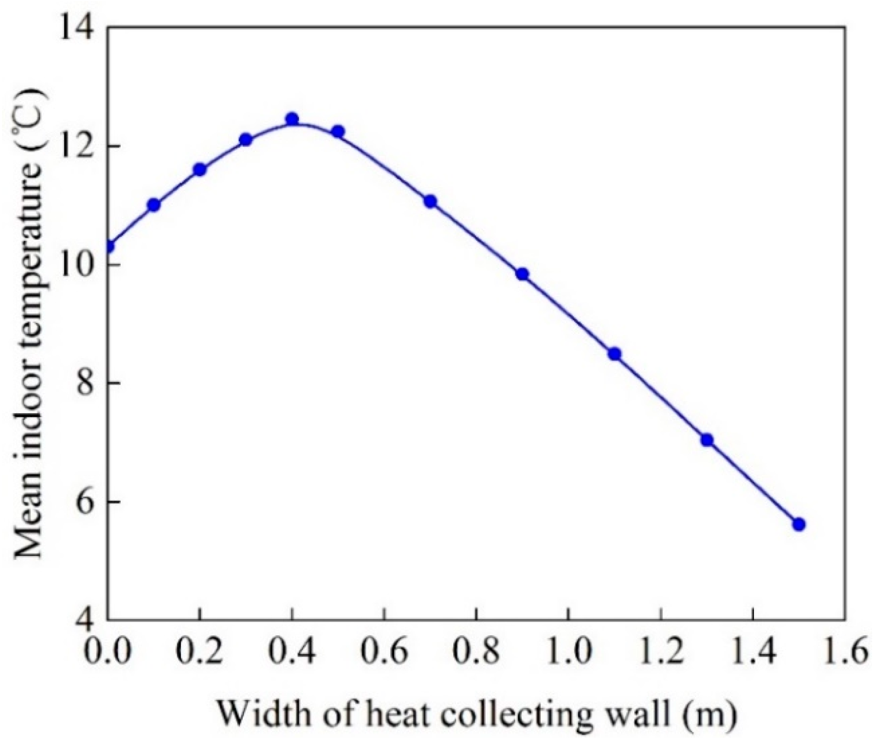
When the height of the collecting wall is constant, the area of heat collecting wall is determined by its width. In the south wall of the passive dormitory, the area of heat collecting wall increases with the decreasing area of the double-glass window. For the south wall, the solar energy can be used in two ways: one way is going through windows into the indoor space directly, the other way is being absorbed by the heating collecting wall and then heating the air in the gap. Different widths of the heating collecting wall are simulated to calculate the indoor air temperature in winter as showed in Figure 14. It can be seen that when the width of heat collecting wall is about 0.4 m, the mean indoor air temperature is higher than others. Furthermore, when the width of heat collecting wall is less than 0.4 m, the heat collecting wall is enough effective to capture more heat than windows. When the width of the heat collecting wall exceeds 0.4 m, the decrease of window area will largely reduce the solar energy transmitted directly into the indoor space, resulting in the drop of indoor air temperature.
3.2.3. Effects of Absorptivity of Heat Collecting Wall
Absorptivity of the heat collecting wall is another important factor affecting the thermal performance of the HHCF. To illustrate the influence of absorptivity on the heating collecting wall, four optional surface coatings including the black paint, the blue paint, the brown paint and the green paint are selected for the comparison. The corresponding values of absorptivity for these four paints are 0.92, 0.88, 0.84, and 0.74 according to the reference [43], respectively. Figure 15 displays the indoor air temperature under different surface coatings of the heat collecting wall. It can be seen that when the absorptivity of the heat collecting wall increases by 0.04, the mean indoor air temperature has a rise of 0.18 °C. This is because the increase of absorptivity of heat collecting wall leads to more solar energy converted into thermal energy and subsequently the indoor air is heated.
3.2.4. Effects of Thermal Performance of Inner Double-Glass Window
For the HHCF, the thermal performance of the inner double-glass window plays an important role in influencing the indoor thermal environment of the building. For double-glass windows, both U-value and solar heat gain coefficient are the dominant parameters affecting the thermal performance of the building.
● U-value
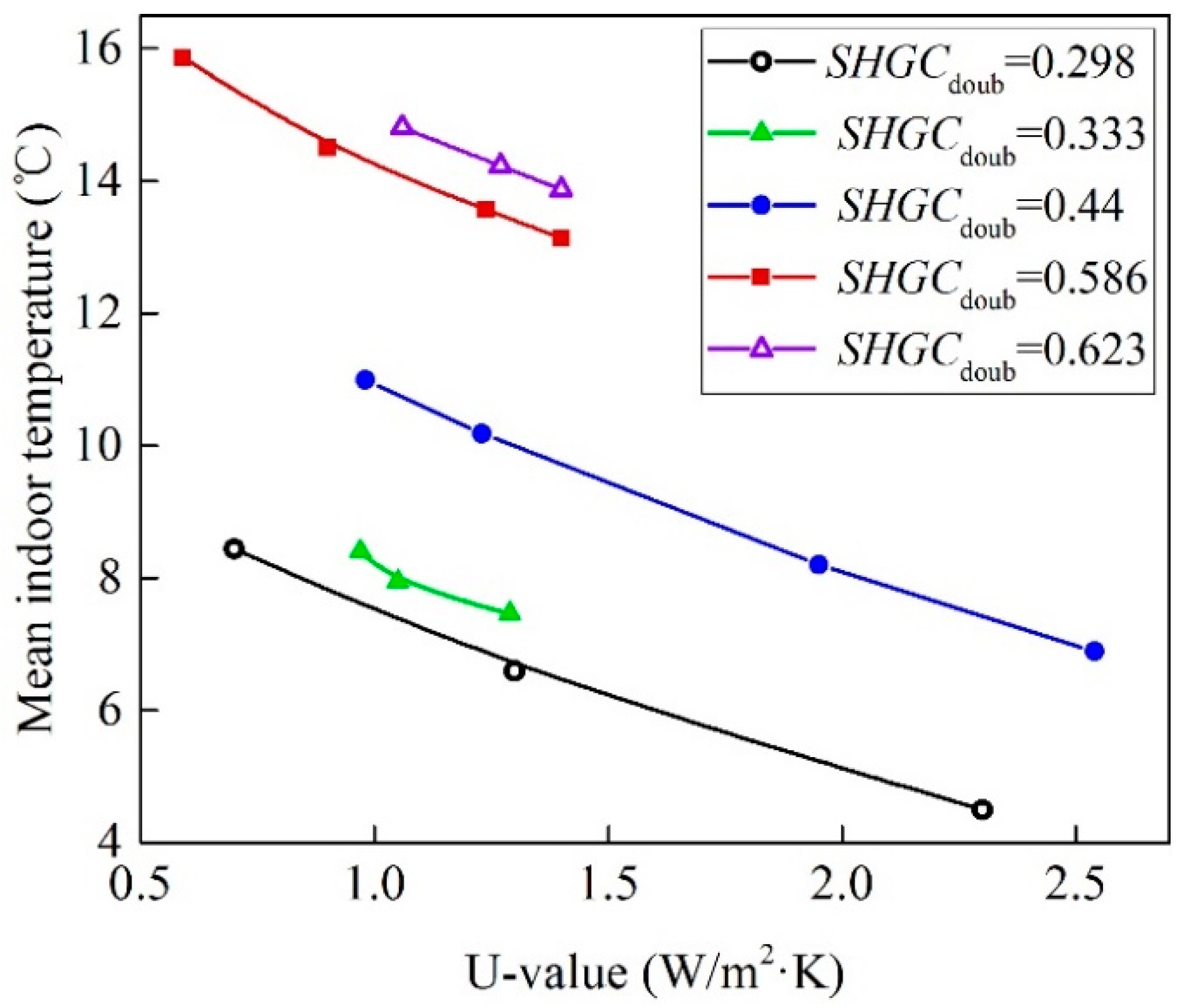
For analyzing the influence of the U-value of the inner double-glass window, some optional real double-glass windows in the window database of TRNSYS [42] are used for simulations. Figure 16 displays the change of the mean indoor air temperature with the U-value of the inner double-glass window. The inner double-glass window with different solar heat gain coefficients of 0.298, 0.333, 0.440, 0.586, and 0.623 are studied as well. As depicted in Figure 16, when the solar heat gain coefficient is constant, the indoor temperature decreases with the increasing U-value. If the U-value increases by 0.1 W/(m2·K), the mean indoor temperature will have a drop of 0.3 °C.
● Solar heat gain coefficient
Figure 17 displays the change of the mean indoor temperature with the solar heat gain coefficient of the inner double-glass window, under the different U-values of 0.59, 1.05, 1.24, and 1.27 W/(m2·K). As depicted in Figure 17, when the U-value is constant, the indoor temperature increases with the solar heat gain coefficient. If the solar heat gain coefficient increases by 0.1, the mean indoor air temperature has a rise of 2.1 °C. In practical applications, to reduce the heating energy use for the building, both a higher solar heat gain coefficient and a lower U-value are necessary for the double-glass window.
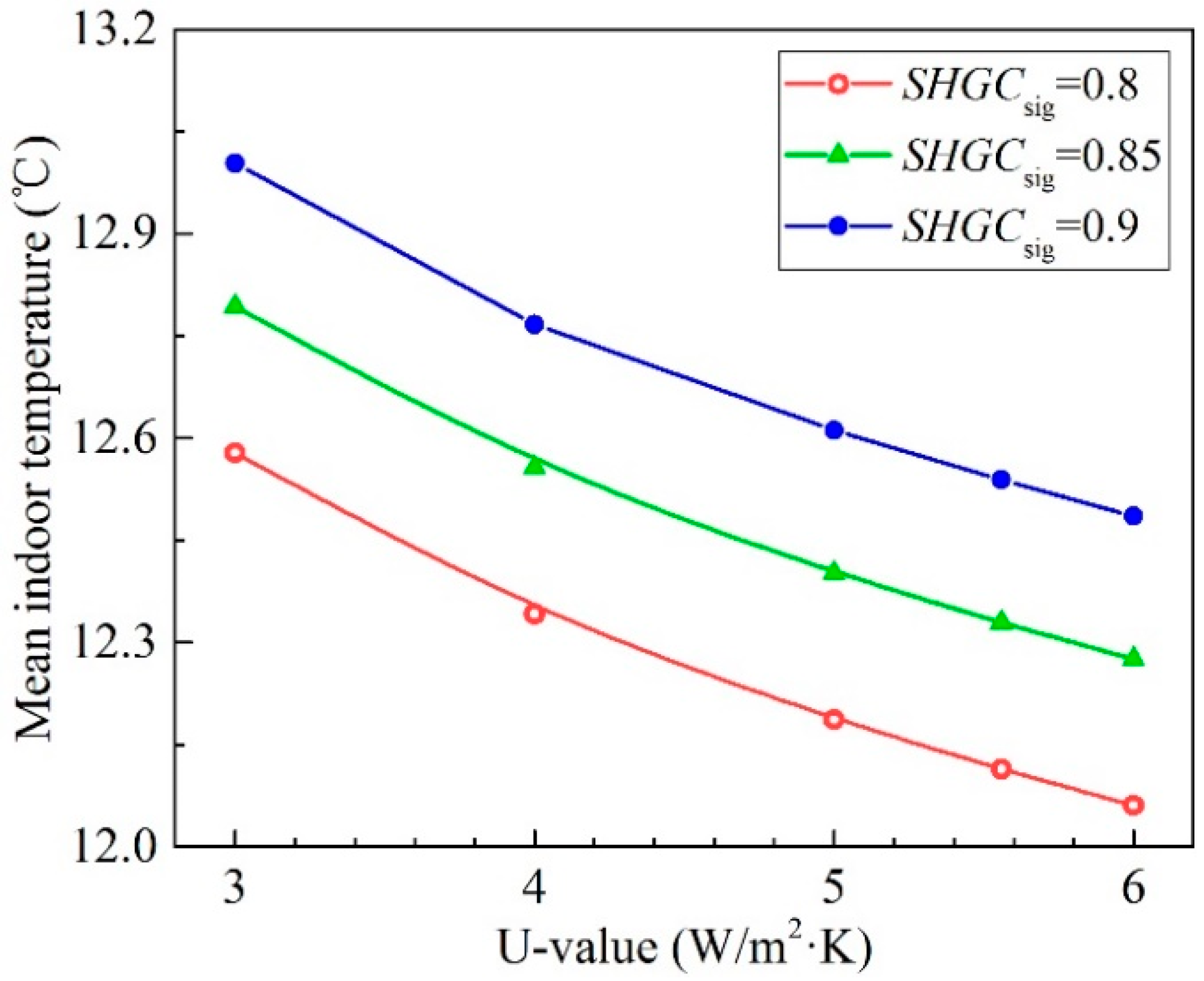
3.2.5. Effects of Outer Single-Glass Window
For single-glass windows, both the U-value and the solar heat gain coefficient are still two important parameters affecting the thermal performance of the building. Generally, the U-value and the solar heat gain coefficient of single-glass windows are higher than those of double-glass windows. Compared with the double-glass window, the single-glass window allows more solar energy transferring into the building and meanwhile increases the heat transmission from the indoor to the outdoor. Figure 18 shows the change of the mean indoor air temperature with the U-value of the outer single-glass window. As shown in Figure 18, when the solar heat gain coefficient is constant, the indoor air temperature decreases with the increasing U-value. If the U-value increases by 1.0 W/(m2·K), the mean indoor temperature has a drop of about 0.17 °C. Similarly, if the solar heat gain coefficient increases by 0.1, the mean indoor temperature rises about 0.4 °C.
3.2.6. Effects of Air Gap Thickness
Thickness of the air gap between the outer single-glass window and the inner double-glass window also has influences on the thermal performance of the HHCF. Figure 19 displays the relationship between the mean indoor air temperature and the thickness of the air gap. It can be seen that when the thickness of the air gap exceeds 30 mm, increasing the air gap thickness by 270 mm results in a drop of 1.24 °C for the indoor air temperature, which means the increase of air gap thickness decreases the thermal performance of the HHCF. Thus, in practical applications of the HHCF, we should try to reduce the air gap thickness as long as the building structure allows. However, according to the requirement of the building structure, the minimum thickness of the air gap should be more than 30 mm. Therefore, in order to improve the thermal performance of the HHCF, the thickness of the air gap should be designed as close as possible to 30 mm.
3.3. Summary of the Presented Results and Discussion
Energy saving potential analysis mentioned above has shown that the HHCF is more energy efficient than the conventional direct solar gain window and the Trombe wall, which provides a novel efficient passive solar energy utilization form. It should be noticed that the HHCF is originally developed for making the most use of solar energy to reduce the heating demand for buildings located in the regions where it is cold in winter and mild in summer, such as the Qinghai–Tibet plateau of China. In these regions, building heating is necessary during the heating season, while in other seasons reasonable natural ventilation can meet the indoor comfort requirement due to the mild outdoor climate and there is no need for building cooling throughout the year.
In order to illustrate the performance of the HHCF, two similar studies performed by Evangelos Bellos et al. [44] and Zou Huifen [45] have been selected for comparsion. Evangelos Bellos et al. proposed an innovative Trombe wall as a passive heating system for a building in Athens. The predicted results shown that the mean indoor temperature for the building with the innovative Trombe wall is about 0.5 °C higher than that with the traditional Trombe wall. In the present study, the indoor temperature increase is about 0.4 °C, a value which is in the same level. The structure of the double-skin façade studied by Zou Huifen et al. is similar to the HHCF in this paper, and it can also decrease the heating energy consumption. Even compared with the plating Low-e film insulating glass curtain wall, the double-skin façade will decrease the energy consumption by 16.0%, while the HHCF in this paper can decrease the total heating need by 21.5%.
4. Conclusions
To improve the thermal performance of passive solar buildings, a hybrid heat collecting façade (HHCF) is proposed in this paper. The heat transfer model for analyzing the thermal performance of the building with the HHCF is established and validated by the experimental results. In order to illustrate the energy saving potential, the heating need of the building with the HHCF is compared with those of the conventional direct solar gain window and the Trombe wall, and results show that the HHCF can reduce the heating energy demand by 40.2% and 21.5%, respectively. A parametric study is performed to determine the thermal performance of the building with a HHCF under various design and operating conditions. It is found that the thermal performance of the HHCF mainly depends on the window operational schedule, the width and absorptivity of heat collecting wall, and the thermal performance of the inner double-glass window. However, other parameters (such as the thermal performance of outer single-glass window and the air gap thickness) of the HHCF could only increase the indoor air temperature by no more than 1.0 °C even within a wide range of these parameters. Apparently, to further improve the indoor air temperature, the U-value of the single-glass window and the thickness of the air gap should be designed as small as possible.
The HHCF mentioned in this paper is suitable for regions where it is cold in winter and mild in summer. If the HHCF is used in hot region, energy consumption performance should be analyzed on an annual basis, since reducing the heating consumption in winter might increase the refrigeration consumption in summer. At the same time, the HHCF in hot regions may cause indoor overheating due to higher outdoor temperature and more solar heat gain in summer. This needs further research to discuss the practicality of the HHCF in other climatic zones.
Author Contributions
Conceptualization, X.W.; Data curation, X.W.; Formal analysis, B.L. and T.Y.; Investigation, X.W. and H.B.; Methodology, X.W.; Project administration, B.L.; Supervision, B.L. and H.B.; Validation, X.W.; Writing—original draft, X.W.; Writing—review & editing, T.Y.
Funding
This research was supported by the Fundamental Research Funds for the Central Universities, Southwest Minzu University, grant number 2018NQN57.
Conflicts of Interest
The authors declare no conflict of interest.
Nomenclature
| A | building envelope area (m2) | Subscripts and superscripts | |
| ACH | air change per hour (1/h) | a | air |
| C | specific heat capacity (J/(kg·K)) | con | building construction |
| D | total thickness of building construction (m) | con, in | interior surface of building construction |
| g | gravity acceleration (m/s2) | con, out | exterior surface of building construction |
| Gr | Grashof number | clo | closed double-glass window |
| h | convective heat transfer coefficient (W/(m2·K)) | cs | horizontal cross section of the heat collecting space |
| H | height of HHCF (m) | diffuse | diffuse radiation |
| I | intensity of solar radiation (W/m2) | direct | direct radiation |
| Ir | incident radiation (W/m2) | doub | double-glass window |
| L | width of double-glass window (m) | hcs | heat collecting space |
| l | characteristic length (m) | hcs-hts | convection from heat transfer space to heat collecting space |
| m | mass flow rate of air in the heat collecting space (kg/s) | hts | heat transfer space |
| Pr | Prandtl number | hts-in | convection from heat transfer space to indoor space |
| q | heat flux (W/m2) | in | indoor |
| qts | solar radiation absorbed by the interior surface (W/m2) | interheat | indoor heat source of building |
| qtsf | transmitted solar radiation through the fenestration (W/m2) | leak | air leak from room |
| Q | heat transfer rate (W) | lw | long-wave radiation exchange |
| S | thickness of air gap (m) | ope | open double-glass window |
| SHGC | solar heat gain coefficient | out | outdoor |
| T | temperature (°C) | r | room |
| U | U-value of window (W/(m2·K)) | sig | single-glass window |
| V | volume (m3) | sig-hcs | convection from single-glass single-glass window to air in the heat collecting space |
| Vm | average wind velocity (m/s) | sig-hts | convection from single-glass single-glass window to air in the heat transfer space |
| W | width of heat collecting wall (m) | tic | conduction through closed double-glass window from heat transfer space to indoor space |
| Greek symbols | va | outlet area of the vent | |
| α | absorptivity of building surface | wa-hcs | convection from heat collecting wall to air in the gap |
| ρ | density (kg/m3) | win | window |
| λ | thermal conductivity (W/(m·K)) | ||
| τ | time (s) | ||
| ν | dynamic viscosity (Pa·s) | ||
| ε | emissivity of building surface | ||
| ξ1 | vent pressure loss coefficient | ||
| ξ2 | air gap pressure loss coefficient | ||
References
- Gil-Baez, M.; Padura, A.B.; Huelva, M.M. Passive actions in the building envelope to enhance sustainability of schools in a Mediterranean climate. Energy 2019, 167, 144–158. [Google Scholar] [CrossRef]
- Wang, R.Z.; Zhai, X.Q. Handbook of Energy Systems in Green Buildings; Springer Nature: Berlin/Heidelberg, Germany, 2018. [Google Scholar]
- Athienitis, A.K.; Barone, G.; Buonomano, A.; Palombo, A. Assessing active and passive effects of façade building integrated photovoltaics/thermal systems: Dynamic modelling and simulation. Appl. Energy 2018, 209, 355–382. [Google Scholar] [CrossRef]
- Duan, S.P.; Jing, C.J.; Zhao, Z.Q. Energy and exergy analysis of different Trombe walls. Energy Build. 2016, 126, 517–523. [Google Scholar] [CrossRef]
- Barea, G.; Ganem, C.; Esteves, A. The multi-azimuthal window as a passive solar system: A study of Heat gain for the rational use of energy. Energy Build. 2017, 144, 251–261. [Google Scholar] [CrossRef]
- Schnieders, J.; Feist, W.; Rongen, L. Passive Houses for different climate zones. Energy Build. 2015, 105, 71–87. [Google Scholar] [CrossRef]
- Nguyen, A.T.; Tran, Q.B.; Tran, D.Q.; Reiter, S. An investigation on climate responsive design strategies of vernacular housing in Vietnam. Build. Environ. 2011, 46, 2088–2106. [Google Scholar] [CrossRef] [Green Version]
- Zhang, T.T.; Tan, Y.F.; Yang, H.X.; Zhang, X.D. The application of air layers in building envelopes: A review. Appl. Energy 2016, 165, 707–734. [Google Scholar] [CrossRef]
- Lebied, M.; Sick, F.; Choulli, Z.; Bouardi, A.E. Improving the passive building energy efficiency through numerical simulation—A case study for Tetouan climate in northern of Morocco. Case Stud. Therm. Eng. 2018, 11, 125–134. [Google Scholar] [CrossRef]
- Shen, C.; Li, X.T. Solar heat gain reduction of double glazing window with cooling pipes embedded in venetian blinds by utilizing natural cooling. Energy Build. 2016, 112, 173–183. [Google Scholar] [CrossRef]
- Egolf, P.W.; Amacker, N.; Gottschalk, G.; Courret, G.; Noume, A.; Hutter, K. A translucent honeycomb solar collector and thermal storage module for building façades. Int. J. Heat Mass Transf. 2018, 127, 781–795. [Google Scholar] [CrossRef]
- Stevanović, S. Optimization of passive solar design strategies: A review. Renew. Sustain. Energy 2013, 25, 177–196. [Google Scholar] [CrossRef]
- Alfredo, F.G. Analysis of the thermal performance and comfort conditions produced by five different passive solar heating strategies in the United States Midwest. Sol. Energy 2007, 81, 581–593. [Google Scholar]
- Sebald, A.V.; Clinton, J.R.; Langenbacher, F. Performance effects of Trombe wall control strategies. Sol. Energy 1979, 23, 479–487. [Google Scholar] [CrossRef]
- Kara, Y.A. Diurnal performance analysis of phase change material walls. Appl. Therm. Eng. 2016, 102, 1–8. [Google Scholar] [CrossRef]
- Jaber, S.; Ajib, S. Optimum design of Trombe wall system in Mediterranean region. Sol. Energy 2011, 85, 1891–1898. [Google Scholar] [CrossRef]
- Ihm, P.; Krartib, M. Design optimization of energy efficient residential buildings in Tunisia. Build. Environ. 2012, 58, 81–90. [Google Scholar] [CrossRef]
- Naylor, D.; Foroushani, S.S.M.; Zalcman, D. Free convection heat transfer from a window glazing with an insect screen. Energy Build. 2017, 138, 206–214. [Google Scholar] [CrossRef]
- Lou, S.W.; Li, D.H.W.; Lam, J.C.; Lee, E.W.M. Estimation of obstructed vertical solar irradiation under the 15 CIE Standard Skies. Build. Environ. 2016, 106, 123–133. [Google Scholar] [CrossRef]
- Parvin, S.; Ahmed, S.; Chowdhury, R. Effect of Solar Irradiation on Forced Convective Heat Transfer through a Nanofluid Based Direct Absorption Solar Collector. In Proceedings of the 7th BSME International Conference on Thermal Engineering, Dhaka, Bangladesh, 22–24 December 2016. [Google Scholar]
- Aksoy, U.T.; Inalli, M. Impacts of some building passive design parameters on heating demand for a cold region. Build. Environ. 2006, 41, 1742–1754. [Google Scholar] [CrossRef]
- Marinoski, D.L.; Guths, S.; Pereiara, F.O.R.; Lamberts, R. Improvement of a measurement system for solar heat gain through fenestrations. Energy Build. 2007, 39, 478–487. [Google Scholar] [CrossRef]
- Zhou, G.B.; Pang, M.M. Experimental investigations on the performance of a collector–storage wall system using phase change materials. Energy Convers. Manag. 2015, 105, 178–188. [Google Scholar] [CrossRef]
- Tian, Z.C.; Zhang, X.K.; Jin, X.; Zhou, X.; Si, B.H.; Shi, X. Towards adoption of building energy simulation and optimization for passive building design: A survey and a review. Energy Build. 2018, 158, 1306–1316. [Google Scholar] [CrossRef]
- Wei, H.; Hu, Z.T.; Luo, B.Q.; Hong, X.Q.; Sun, W.; Ji, J. The thermal behavior of Trombe wall system with venetian blind: An experimental and numerical study. Energy Build. 2015, 104, 395–404. [Google Scholar]
- Gou, S.Q.; Nik, V.M.; Scartezzini, J.L.; Zhao, Q.; Li, Z.R. Passive design optimization of newly-built residential buildings in Shanghai for improving indoor thermal comfort while reducing building energy demand. Energy Build. 2018, 169, 484–506. [Google Scholar] [CrossRef]
- Harkouss, F.; Fardoun, F.; Biwole, P.H. Passive design optimization of low energy buildings in different climates. Energy 2018, 165, 591–613. [Google Scholar] [CrossRef]
- Larsen, S.F.; Rengifo, L.; Filippin, C. Double skin glazed façades in sunny Mediterranean climates. Energy Build. 2015, 102, 18–31. [Google Scholar] [CrossRef]
- Samuelson, H.; Claussnitzer, S.; Goyal, A.; Chen, Y.J.; Alejandra, R.C. Parametric energy simulation in early design: High-rise residential buildings in urban contexts. Build. Environ. 2016, 101, 19–31. [Google Scholar] [CrossRef] [Green Version]
- Owrak, M.; Aminy, M.; Jamal-Abad, M.T.; Dehghan, M. Experiments and simulations on the thermal performance of a sunspace attached to a room including heat-storing porous bed and water tanks. Build. Environ. 2015, 92, 142–151. [Google Scholar] [CrossRef]
- Gong, X.Z.; Akashi, Y.; Sumiyoshi, D. Optimization of passive design measures for residential buildings in different Chinese areas. Build. Environ. 2012, 58, 46–57. [Google Scholar] [CrossRef]
- Ruiz, M.C.; Romero, E. Energy saving in the conventional design of a Spanish house using thermal simulation. Energy Build. 2011, 43, 3226–3235. [Google Scholar] [CrossRef]
- Klein, S.A.; Beckman, W.A.; Mitchell, J.W.; Duffie, J.A.; Duffie, N.A.; Freeman, T.L. TRNSYS Manual; University of Wisconsin-Madison: Madison, WI, USA, 2007. [Google Scholar]
- Pantankar, S.V. Numerical Heat Transfer and Fluid Flow; Hemisphere: New York, NY, USA, 1980. [Google Scholar]
- Hottel, H.C.; Sarofim, A.F. Radiative Transfer; McGraw-Hill: New York, NY, USA, 1967. [Google Scholar]
- Cengel, Y.A.; Ghajar, A.J. Fundamentals of Thermal-Fluid Sciences; McGraw Hill: New York, NY, USA, 2001. [Google Scholar]
- Park, B.; Krarti, M. Development of a simulation analysis environment for ventilated slab systems. Appl. Therm. Eng. 2015, 87, 66–78. [Google Scholar] [CrossRef]
- Xiao, W. Study of the Direct-Gain Solar Heating in Remote Southwest Tibet; Tsinghua University: Beijing, China, 2010. [Google Scholar]
- He, L.Q.; Ding, L.X. The Calculation Basis of Thermal Physics for SOLAR Building; Press of University of Science and Technology of China: Hefei, China, 2010. [Google Scholar]
- Klien, S.A.; Theilacker, J.C. An algorithm for calculating monthly-average radiation on inclined surfaces. J. Sol. Energy Eng. 1981, 103, 29–33. [Google Scholar] [CrossRef]
- Meteorological information center of China, Department of building technology science of Tsinghua university. Special Meteorological Data Sets for the Analysis of the Thermal Environment of Chinese Buildings; China building industry press: Beijing, China, 2005. [Google Scholar]
- TRNSYS 18 Manuals, Component Mathematical Reference. Available online: http://sel.me.wisc.edu/trnsys/user18-resources/index.html (accessed on 1 November 2018).
- Zhu, Y.X.; Yan, Q.S. Built Environment, 2nd ed.; China building industry press: Beijing, China, 2007. [Google Scholar]
- Bellos, E.; Tzivanidis, C.; Zisopoulou, E.; Mitsopoulos, G. An innovative Trombe wall as a passive heating system for a buildingin Athens—A comparison with the conventional Trombe wall and theinsulated wall. Energy Build. 2016, 133, 754–769. [Google Scholar] [CrossRef]
- Zou, H.F.; Fei, Y.C.; Yang, F.H.; Tang, H.; Zhang, Y.; Ye, S. Mathematical Modeling of Double-Skin Facade in Northern Area of China. Math. Probl. Eng. 2013, 2013. [Google Scholar] [CrossRef]
Figure 1.
Schematic diagram of the hybrid heat collecting facade (HHCF). (a) with double-glass window open; (b) with double-glass window closed.
Figure 1.
Schematic diagram of the hybrid heat collecting facade (HHCF). (a) with double-glass window open; (b) with double-glass window closed.

Figure 2.
Heat transfer processes of HHCF.

Figure 3.
Heat transfer process of the building construction.

Figure 4.
Heat balance solution procedure for the building with the HHCF.

Figure 5.
Test room of the dormitory building.

Figure 6.
Geometry of the room studied.

Figure 7.
Indoor temperature test.

Figure 8.
Meteorological data measurement.

Figure 9.
Comparison of Results from experiments and simulations. (a) Indoor air temperature; (b) Air temperature of heat transfer space; (c) Interior surface temperature of west wall.
Figure 9.
Comparison of Results from experiments and simulations. (a) Indoor air temperature; (b) Air temperature of heat transfer space; (c) Interior surface temperature of west wall.


Figure 10.
Three cases studied.

Figure 11.
TRNSYS model for Case 1 and Case 2. (a) TRNSYS model for Case 1; (b) TRNSYS model for Case 2.
Figure 11.
TRNSYS model for Case 1 and Case 2. (a) TRNSYS model for Case 1; (b) TRNSYS model for Case 2.


Figure 12.
Comparisons of indoor air temperature and heating energy demand on heating design day. (a) Indoor air temperature for studied cases; (b) Heating energy demand for studied cases.
Figure 12.
Comparisons of indoor air temperature and heating energy demand on heating design day. (a) Indoor air temperature for studied cases; (b) Heating energy demand for studied cases.


Figure 13.
Air temperatures under diverse window schedules.

Figure 14.
Mean indoor air temperature under different widths of heat collecting wall.

Figure 15.
Indoor air temperature for different values of absorptivity of heat collecting wall.

Figure 16.
Mean indoor air temperature for various U-values of double-glass window.

Figure 17.
Mean indoor temperature under various solar heat gain coefficients.

Figure 18.
Mean indoor air temperature under various U-values of single-glass window.

Figure 19.
Mean indoor air temperature under various thicknesses of air gap.


Table 1.
Constructions of the building.
| Construction | Material | Thermal Conductivity (W/(m·K)) | Heat Capacity (J/(kg·K)) | Density (kg/m3) |
|---|---|---|---|---|
| Exterior wall | 80 mm polyurethane | 0.033 | 1380 | 40 |
| 240 mm brick wall | 0.89 | 1000 | 1800 | |
| 20 mm Cement mortar | 0.93 | 1050 | 1800 | |
| Interior wall | 20 mm Cement mortar | 0.93 | 1050 | 1800 |
| 240 mm brick wall | 0.89 | 1000 | 1800 | |
| 20 mm Cement mortar | 0.93 | 1050 | 1800 | |
| Ceiling | 20 mm Cement mortar | 0.93 | 1050 | 1800 |
| 180 mm concrete | 1.74 | 920 | 2500 | |
| 20 mm Cement mortar | 0.93 | 1050 | 1800 | |
| Door | 60 mm wood | 0.15 | 1630 | 608 |
| HHCF | 3 mm single-glass window, U = 5.56 W/(m2·K); SHGC = 0.9; 120 mm-thickness air gap; 12 mm double-glass window, U = 2.83 W/(m2·K); SHGC = 0.76; 0.5 m-width for each heat collecting wall (W = 0.5 m); Materials of the heat collecting wall is the same with the exterior wall Absorptivity of the heat collecting wall is 0.8; 2.3 m-width for double-glass window (L = 2.3 m) | |||
Table 2.
Summary of indoor air temperature and total heating energy demand in heating season.
| Indoor Air Temperature (°C) | Total Heating Energy Demand (kWh/m2) | |||
|---|---|---|---|---|
| Mean | Minimum | Maximum | ||
| Case 1 | 17.5 | 10.4 | 21.9 | 47.9 |
| Case 2 | 18.2 | 10.5 | 26.7 | 36.6 |
| Case 3 | 18.6 | 11.0 | 27.1 | 28.7 |
Table 3.
Indoor air temperature ranges under different window schedules.
| Schedule A | Schedule B | Schedule C | Schedule D | |
|---|---|---|---|---|
| Time to open windows | With windows closed all day | 8:00 | 9:00 | 11:00 |
| Time to close windows | 18:00 | 17:00 | 15:00 | |
| Indoor air temperature (°C) | 6.7~13.2 | 8.2~19.0 | 8.6~19.0 | 7.8~17.5 |
© 2019 by the authors. Licensee MDPI, Basel, Switzerland. This article is an open access article distributed under the terms and conditions of the Creative Commons Attribution (CC BY) license (http://creativecommons.org/licenses/by/4.0/).
Share and Cite
MDPI and ACS Style
Wang, X.; Lei, B.; Bi, H.; Yu, T. Study on the Thermal Performance of a Hybrid Heat Collecting Facade Used for Passive Solar Buildings in Cold Region. Energies 2019, 12, 1038. https://0-doi-org.brum.beds.ac.uk/10.3390/en12061038
AMA Style
Wang X, Lei B, Bi H, Yu T. Study on the Thermal Performance of a Hybrid Heat Collecting Facade Used for Passive Solar Buildings in Cold Region. Energies. 2019; 12(6):1038. https://0-doi-org.brum.beds.ac.uk/10.3390/en12061038
Chicago/Turabian StyleWang, Xiaoliang, Bo Lei, Haiquan Bi, and Tao Yu. 2019. "Study on the Thermal Performance of a Hybrid Heat Collecting Facade Used for Passive Solar Buildings in Cold Region" Energies 12, no. 6: 1038. https://0-doi-org.brum.beds.ac.uk/10.3390/en12061038
Note that from the first issue of 2016, this journal uses article numbers instead of page numbers. See further details here.