Analysis of the Gearbox Oil Maintenance Procedures in Wind Energy


1
Eolia Renovables, 29010 Málaga, Spain
2
Department of Electrical Engineering, School of Engineering, University of Malaga, 29016 Málaga, Spain
*
Author to whom correspondence should be addressed.
Energies 2020, 13(13), 3414; https://0-doi-org.brum.beds.ac.uk/10.3390/en13133414
Submission received: 19 May 2020
/
Revised: 22 June 2020
/
Accepted: 29 June 2020
/
Published: 2 July 2020
(This article belongs to the Special Issue Advances in Maintenance Management)
Abstract
:This work analyzes the impact of the operation and maintenance procedure on the condition of gearbox oil. The analytical results reveals how different scenarios modify them. The analysis is based on key operational data collected from 30 different multi-megawatt wind turbines at different locations in Spain with a variety of technologies from different top-tier manufacturers. The study includes various situations and decisions, such as leakage and replacement of oil, offline filter installation, oil brand change, substitution of valves, and even the position where the sample is taken and how these situations can provoke false warnings that trigger modifications in the operation and maintenance of wind farms with new unnecessary tasks and costs. The experimental results conclude that complete and reliable information is crucial when warning about risk situations. It is not possible to take appropriate actions without accurate information and consequently the spread of the problem cannot be stopped.
1. Introduction
The wind industry has experienced enormous growth in recent years, from 24 GW in 2001 to over 591 GW in 2018 [1], which represents an increase of over 2000% in the last 15 years. This rise is expected to continue within the framework of agreement from the international community to promote cleaner and more sustainable energy [2]. Along with the increasing values of the overall installed capacity, wind energy has become the most mature and developed renewable technology [3]. It plays a fundamental role in the current energy mix and provides high performance with improved reliability [3].
Wind turbines are operated based on maintenance strategies that are previously designed by manufacturers. These strategies have evolved over the years and will continue to do so in the future [4]. This is due to the development of new maintenance techniques, the emergence of new tools and spare parts and, of course, a wider knowledge of assets (local and global), either from the maintainer or the promoter [5]. The special features of the wind turbines imply a challenge for these new maintenance techniques that make each wind farm (and sometimes each wind turbine) special, with specific requirements and preventive tasks. Some of these special features are: (i) evolution in size, with increasing dimensions, especially of towers or blades (the cranes and substitution procedures for the substitution of a 30-m long blade are completely different to the case when the length of the blade is 60 m); (ii) evolution in components, with continuous modifications in mechanical, electrical, electronic, or hydraulic fields; (iii) age of the wind turbine, where specific checklists for determined periods of time are constantly being adapted; or (iv) variety of models and versions of the wind turbines. The same maintenance task can be very different depending on the dimensions of the wind turbine.
The operation and maintenance (O&M) of a wind turbine is not simple: (i) it is necessary to work in an installation that is located more than 80 m high (on average); (ii) it depends on atmospheric conditions such as wind, cold, heat, thunderstorms, to name a few; (iii) it involves working with electrical, electronic, mechanical, hydraulic, physical, and chemical processes; and (iv) hundreds of signals are generated in a wind farm producing millions of data that must be processed and analyzed [6]. These variables depend on all kinds of internal and external factors, and it is not straightforward to correlate them together or add others that are not easily standardized in order to reach reliable conclusions [7]. Despite the circumstances that hinder the O&M of a wind farm, high levels of availability and capacity factor, in addition to wind turbine conservation, are always sought to be achieved.
Even though individual components have been commonly used in the industry (e.g., gearboxes, generators, converters or transformers), their inclusion into newly designed multi-MW wind turbine generation (WTG), with all the aforementioned operating conditions, undoubtedly, has an impact on the uncertainty of the equipment lifespan. Aspects such as the limited space in wind turbines, the aggressive and special environmental conditions to which they are subject to (especially in offshore locations), or the lack of standardization between different technologies have historically been key factors in the global operation of the assets [8].
The gearbox is one of the elements subjected to the greatest loads and entails high substitution costs because it requires the intervention of external large-tonnage cranes. A standard gearbox in a 2 MW wind turbine can weigh about 15 tons, has more than 20,000 kNm of torque, and has about 250 L of oil. It usually has a combination of planetary gears and parallel shafts to reach a transformation ratio that can be around 1:105 in a standard high-speed 2 MW wind turbine [9]. Depending on the turbine model, the gearbox can have different dispositions and design of gears, bearings, and shafts. In the case of the gearless drive concept, the manufacturer looks to avoid the maintenance costs fixed to a component such as a gearbox in addition to other benefits. The equipment is fixed to the rest of the wind turbine on two silent block supports attached to the frame. In the front, it will be attached to the main shaft or in some cases directly to the rotor, whereas in the back, it will be fixed to the flexible compact joint (cardan) and subsequently to the generator (the mechanical brake is usually coupled directly to the quick shaft of the gearbox). This flexible joint is the weakest part in case of misalignment in the power train and it is the one that assumes the loads to protect important equipment such as the gearbox or generator [9].
In the case of the gearbox, there are routine tasks included in the preventive maintenance. To name a few, some of the actions that are checked periodically, include: (i) cleaning of cooling system; (ii) revision of the silent blocks rubber; (iii) revision of the condition of the joint with the main shaft; (iv) check of oil level or pressure value; (v) control of tightening screws. According to their relevance, other techniques are used in order to determine the condition of the gearbox and to avoid corrective actions. The most common ones are: (i) videoscopes, to directly observe the condition of the internal components; (ii) vibration analysis, either occasionally or permanently; or (iii) oil analysis, with the double function of establishing the condition of the gearbox and the oil itself [10].
In spite of the impact on the reliability of WTG, it is worth highlighting that there are previous studies on the gearbox oil maintenance procedures [11], but the body of knowledge on this specific topic is limited. One of the reasons for this lack of analysis is that the current casuistry concerns a complex environment, such as a wind turbine, at more than 80 m high, where situations are not reported in many cases. This makes it difficult to collect and analyze the data [12]. However, there is information regarding the analyses of oils in wind turbine gearboxes, as well as the relationship with other predictive systems such as online monitoring systems [13]. In this case, much of the relevant information comes directly from the companies or laboratories involved in this sector rather than from academic publications.
This study aims to point out, with an in-depth analysis, the specific aspects that are part of the daily routines within the O&M of a wind farm and which can alter the results of the oil analysis results of the gearboxes. These results are critical when making decisions about the gearbox and how to operate the assets. For this reason, the insight and conclusions that have been extracted from this study are expected to provide a high archival value and to set the basis for future actions at industry. Once the effects of the different actions are determined, the operator and the maintainer can choose to modify work protocols or reinterpret the results, depending on the specific case.
The main contributions of this work are: (i) proving that routine actions in preventive maintenance can alter the oil analysis results; (ii) highlighting the consequences of false warnings, which trigger modifications in the operation of the wind farm with new unnecessary tasks and costs; (iii) revealing that the use of unreliable information makes it impossible to prioritize the preventive and predictive maintenance over corrective maintenance. Extensive experimental results confirm that the incomplete or erroneous information in the O&M procedure may lead to false alarms and/or unnecessary corrective maintenance (with an extra cost). This analysis provides a novel insight into different aspects of the gearbox oil maintenance that aims to provide a high archival value for researchers and practitioners in this field.
The paper is structured as follows. Section 2 firstly reviews some background about the O&M in WTG, focusing on the tasks and routines of the preventive and predictive maintenance of wind turbines gearboxes. Section 3 analyses the essential components for the good maintenance of gearboxes in WTG, including the oil and its physical-chemical analysis. Section 4 provides experimental results from 30 wind turbines at 3 different locations and different technologies in order to analyze and discuss real situations where results can be altered. Finally, the most relevant conclusions are summarized in the last section.
2. Generalities of Gearbox Oil Analysis
Among the main functions of the lubricant are those of: (i) separating from the tread surfaces, reducing wear; (ii) ensuring machine cooling, improving the dissipation of heat; (iii) reducing friction and increasing efficiency, propitiating energy savings; (iv) protecting the bearing, both from corrosion and from contamination and (v) absorbing wear particles, that is, cleaning the system.
To meet these objectives, the oil needs to preserve its properties during its useful life. These properties should ideally be: (i) resistance to aging and oxidation; (ii) low foaming; (iii) good air separation capacity; (iv) high load carrying capacity; (v) neutrality to materials (ferrous, non-ferrous, joints, paints); (vi) ability to withstand high and low temperatures; (vii) good viscosity—temperature behavior; and (viii) detergency (i.e., the ability to clean and dissolve dirt in the hydraulic circuit).
To check that the oil keeps the aforementioned properties in an optimal state, oil analyses are carried out providing information on the condition of the lubricant, the operational environment (environment in which the machine operates), and the condition of the gearbox (internal wear of the equipment).
The state of the oil is determined by checking its contamination and degradation [14], that is, the loss of lubricating capacity caused by a variation of its physical and chemical properties (especially those of its additives). The contamination of the oil can be determined by quantifying in a sample of the lubricant the content of metallic particles, proportion of water, carbonaceous materials, and insoluble particles, i.e., everything that is in the fluid and does not belong to it (see Table 1). The degradation can be evaluated by measuring the viscosity, detergency, acidity, and dielectric constant [15].
It is convenient to indicate that contamination and degradation are not independent phenomena, since pollution causes degradation and the latter can in turn increase pollution. The contamination in oil has a direct effect on the degradation [16]. However, these consequences will be different depending on the type of degradation:
- −
- Not only the oxidation, but also the additive depletion forms deposits that can restrict the flow to bearings, producing an increased bearing and gear teeth wear and eventually gearbox failure.
- −
- When the sediments or metallic particles become bigger, damage in the bearings and gears of the gearbox can occur. These particles can erode the external layer of these elements, creating a weak point and possible future greater damages. The reason is that it is the hardest layer and provides hardness (the rest of the material inside is more ductile).
- −
- The wear of the additives reduces the capacity of the oil to protect the bearings and gears.
3. Executed Gearbox Oil Operation Tests in Wind Turbines
This work considers five different tests that have been carried out in a total of 30 wind turbines on three independent wind farms. The different technologies of the wind turbines under study provide a full picture of the gearbox oil operation procedure, including the analysis of the effects of different actions on the oil state and the impact on the oil analysis results. Among the different actions that are performed in the O&M, the five with a higher relevance are leakage and oil filling, brand (and features) oil replacement, installation of portable off-line filter, high temperature of oil, and replacement of thermostatic valves and position where taking the sample has been taken. A detailed analysis of the aforementioned actions, devoting a section to each of them, is provided next.
3.1. Leakage and Oil Filling
Description event: the gearboxes are equipped with numerous joints, seals, valves, and filters where oil leaks may occur [17], either by deterioration in any of the components, mismatches, or even human errors in handling.
Potential effect on oil/equipment/analysis result: When a leak appears in a gearbox, there is a loss of oil volume, which generates an increase in temperature and oil degradation due to a high level of stress [18]. When the oil is at minimum levels, a warning alarm or even a stoppage of the wind turbine occurs in order to avoid working in risky conditions that might damage the equipment. To avoid this situation, the usual practice is to increase the level filling with new oil, obviously with intact properties, which produces a contamination (positive in this case) that alters the evolution of the previous oil analysis results.
From a maintenance point of view, this situation should be something exceptional and not routine because it would have three consequences: (i) if a leak appears, good practices say it must be repaired, otherwise it will continue leaking permanently; (ii) reliable analytics will never be available because the oil will always have new refills, masking the real status, not only of the oil, but also the bearings and gear teeth; and (iii) the trends of the different analysis would not have any value since they cannot compare the evolution of the different elements (additives, wear particles, viscosity, water, etc.). If there is no reliable information that warns of risk situations, no action can be taken or perhaps erroneous or unnecessary action are taken.
3.2. Brand (and Features) Oil Replacement
Description event: when the maintainer replaces the oil, either due to a technical decision on the characteristics of the used oil or simply because it has reached the end of its useful life, it is possible that the brand changes [19].
Potential effect on oil/equipment/analysis result—when replacing the oil of a gearbox for a different brand, the following steps are carried out:
- Withdrawal of the used oil.
- Wash” with new oil. This task is not usual and depends on the decision of the maintainer to do so or not. This action seeks a better elimination of the remains of the former oil, since the configuration of the gearbox with many gears and bearings (with small holes of difficult access) makes the full elimination practically impossible.
- Oil filter replacement.
- Flushing to remove all traces of the retired oil. This operation seeks removing the maximum amount of oil and remains of dirt with compressed air.
- Filling with new oil.
Although most components of oils for gearboxes are the same, the percentage of additives may vary or may even have some differences. In this case, there is an alteration in the sequence of values of the historical result series from oil analyses that could affect their interpretation, causing repetition of samples or analysis and even application of unnecessary actions in the gearbox, which implicates relevant investments. If a false warning appears, new unnecessary actions, such as endoscopies or vibration analysis, would be required [20].
In the first case, a videoscope is used to inspect the details of the bearings and gear teeth from different inspection covers of the gearbox. These works must be executed by an expert, not only because of the necessary skills to introduce the videoscope through small gaps, but also for the necessary experience to interpret the captured images. The duration of these works can be around five hours, which implies a significant cost, considering the travel and associated loss of production.
Regarding the vibration analysis, where the frequencies of the bearings failure are analyzed, it is necessary to know the frequency data of the different bearings. In some cases, this equipment is installed in the wind turbine permanently, whereas in the other cases, a portable equipment is used. The most important condition to achieve reliable results is to execute the test with a minimum wind speed value (around 7 m/s), so the process consists of: (i) stop the turbine; (ii) install the equipment; (iii) get out the turbine; (iv) run the turbine for a couple of hours or even days (this decision depends on the expert); (v) stop the turbine; (vi) remove the equipment; (vii) get out the turbine, and (viii) run the turbine. In this case, a relevant investment is also necessary.
3.3. Installation of Portable Off-Line Filter
Description event: most gearboxes of multi-megawatt wind turbines have an oil filter. In addition, there is a second piece of equipment called an off-line filter, which is more effective and provides a higher quality filtering. The scheme for the gearbox off-line oil filtration equipment is depicted in Figure 1. This type of filter can be installed permanently or temporarily in order to improve oil properties. The purpose of the off-line filter installation is to reduce: (i) the humidity level to around 50%; (ii) the ppm of copper (Cu) and iron (Fe) by 30%; (iii) the ppm of Silicon (Si) particles (not in the case of silicon joints); (iv) the level of particles around two ISO classes (Table 2); and (v) the PQ index level (ferromagnetic particles) and small particles of wear [21].
In the case of an off-line filter, the pressure and flow are low and constant, unlike in the on-line filter, where they are high and fluctuant. This implies that the particle retention is higher and consequently the filtration is more effective.
Potential effect on oil/equipment/analysis result: In the case of permanent off-line filters, the positive effect is continuous and stable over time, but in the case of portable equipment, the improvement becomes evident by comparing the oil analysis results before and after its installation. This type of portable filtering action is an economical solution to improve the quality of the oil in a wind farm with just one piece of equipment, instead of installing one permanent filter in each wind turbine. As explained in Section 2, the contamination in the oil has a direct effect on the degradation. In this case, the installation of this type of filter improves the cleanliness of the oil and the protection of the gearbox.
3.4. High Temperature of Oil and Replacement of Thermostatic Valves
Description event: the temperature of the oil is continuously monitored. These values should be in a range of temperature in order to avoid degradations due to thermal processes. The thermovalves provide reliable control of fluid temperatures to maintain the temperature of the oil in some predefined operating ranges [23].
Most wind turbines have warning and danger levels (which usually implies the stoppage of the turbine). In the first case, the wind turbine does not stop, but should be repaired. Additionally, the predictive temperature analysis can indicate if one or several wind turbines temperatures are not in line with the average of the rest (when there is an important population of units), detecting an anomaly that must be attended to.
Sometimes it is necessary to replace one of these devices that are in contact with the oil because some pieces suffer degradation and the operation of the component is consequently deficient.
Potential effect on oil/equipment/analysis result: The thermovalves are in the oil cooling circuit and their internal pieces are in permanent contact with the oil. When these pieces suffer degradation and are substituted, the new ones contain levels of iron and copper in their composition in higher levels, so the oil indirectly suffers an increase in the levels of these wear components.
3.5. Position of Sample Taking
Description event: the position of the sample taking is usually determined by: (i) the procedure of each maintainer; (ii) the design of the gearbox; and (iii) its own know-how [24]. The sample should be taken in the same position, but due to different circumstances, this does not always hold true. Figure 2 shows different options for sampling positions.
Potential effect on oil/equipment/analysis result: if the sample is taken before the filtering (option 1 in Figure 2), the knowledge of the gearbox state is prioritized. Conversely, if it is taken after the filter (option 2 in Figure 2), the oil condition is prioritized. The condition of the filter is also important. Results should typically improve with new filters, but significant disturbances can be obtained if the filter is dirty.
In this case, depending on the position of the sampling, the consequences can be different: from the need to replace the filter to major actions explained in points 3.1 and 3.2, such as videoscopes or vibration analysis. In many cases, these predictive actions implicate the change of a specific bearing but avoid the substitution of the complete gearbox.
4. Results
The five O&M actions described in the previous section are examined and discussed next in the light of extensive experimental results. Each action is individually studied in the following sections, providing real examples from 30 wind turbines in 3 different locations.
4.1. Leakage and Oil Filling
The concentration of each of the parameters included in the oil—measured as parts per million—is typically used in the oil analysis. In this test, the evolution of additives such as zinc, phosphorus, and sulphur was checked in a gearbox of a 2.5 MW turbine at five different moments with a frequency of six months (test 1, test 2, test 3, test 4, and test 5), from 2015 to 2017. The total capacity of the oil in the gearbox is 340 L and the refills were 40 L between test 3 and test 4 (second quarter of 2016). Other samples from the same wind farm were rejected during the study due to external situations that altered the trend. In some cases, substitution of the oil or different contaminations appeared during the period of the study. The oil was analyzed in a world-renowned laboratory.
The normal trend with time and use is to maintain or decrease the additives (zinc, phosphorus, and sulphur) due to degradation of the oil and additives’ wear. In this case, the theoretical trend was predicted, extrapolating the slope of the actual results from previous samples. However, in this case—the leakage of old oil and subsequent partial replacement of new oil with intact characteristics after test 3—the aforementioned additives increased. Figure 3, Figure 4 and Figure 5 compare, in five different tests, the theoretical and measured results of the evolution of additives. The evident effect of the filling in the values of these three additives is observed.
The experimental results from Figure 3, Figure 4 and Figure 5 show that the refill produces a positive contamination that alters the evolution of the theoretical values in the oil analysis results.
In this case, it is necessary to check if there is a leak and repair it to ensure reliable analytics that do not mask the real status of the oil and the gearbox.
4.2. Brand (and Features) Oil Replacement
The experimental results for this second action consider the replacement of the oil brand in 13 wind turbines. The comparison includes two oil brands that are suitable for the same equipment, in this case, a gearbox of a 1.5 MW wind turbine in the same site and meteorological conditions. Substitution of the oil was done in the first quarter of 2016 and the study collected data from 2012 to 2016. In this case, all the samples were valid, and no external situations altered the trends. The samples were analyzed in a world-renowned laboratory. The danger limits for these components were supplied by the manufacturers of the two oils.
Analysis of the chemical composition of both oils [25] revealed the presence of additives such as molybdenum, magnesium, and zinc in the chemical composition of the first oil in high amounts, but were non-existent in the second oil. In fact, the values permitted by each are different—they were much more restrictive in oil 2 (oil without these components in its composition) than oil 1, as shown in Table 3. These values are defined by the manufacturers of each brand and model of oil.
In the case of oil 2, two situations with different limits are analyzed: the first scenario considers new oil and gearbox, and the second scenario takes into account the case when a flushing of the gearbox is performed before the new oil is introduced [26]. It is assumed in both scenarios that there will always be remnants of the previous oil (flushing consists of the cleaning of the different components inside the gearbox with pressurized air). In the opposite order, that is, the gearbox was using oil 2, which was then replaced by oil 1 (oil with these specific components), there would be no problem because the values would always be below the danger limits.
After the replacement of these two brands of oils in 13 gearboxes, the results of the evolution of different items analyzed as additives and wear particles are shown in Figure 6, Figure 7 and Figure 8. The analyses in tests 1 to 4 are executed each six months and the change in oil brand is performed before test 3. The red dashed line in Figure 6, Figure 7 and Figure 8 depicts the maximum values allowed for the additive concentration. This red dashed line decreases from test 3 to test 4 due to the difference in the maximum value allowed for each oil brand. The black dashed line in Figure 6, Figure 7 and Figure 8 depict a zoom of test 4.
Analytically calculating this situation, it is necessary to estimate the liters of oil left in the gearbox after substitution of the old oil.
where NC is the new concentration, CNO is the concentration of the new oil (oil 1), NQ is the new quantity of oil (liters) of oil 1, COO is the concentration of the old oil (oil 2), NQ is the remaining quantity of oil (liters) of oil 2, and TQ is the total quantity of oil (liters) in the gearbox.
Estimating 15 remaining liters in the case of the Zn and recollecting the total quantity of new oil (320 L), the result would be:
As a consequence of this oil brand replacement, in a normal case, the result of the 13 tests of new oil would be deemed “danger”, considering that there are components such as molybdenum, zinc, and magnesium that widely exceed the admissible ranges for this oil brand (<20 mg/kg). However, in this case, the oil is substituted after the flushing inside the gearbox; hence, the values would be within the higher limits established by the oil manufacturer (<150 mg/kg). Consequently, it is mandatory to make a good evaluation of the results to know not only that the oil brand has been replaced, but also to know that a flushing has been carried out.
If the values are far above the new limits, refilling (if the laboratory and the maintainer agree to do so) would be necessary; even the substitution of the total oil and a new flushing would be necessary (as explained in Section 3.2).
4.3. Installation of Portable Off-Line Filter
The oil analysis was carried out on six 1.5 MW turbines in the same wind farm before and after the installation of a portable filter. The portable filter was installed during the second quarter of 2017 for an average of one week in each of the turbines, except in the test 2 turbine, where the period was extended to two weeks due to high levels of contamination. The samples were taken just before the filtering and were analyzed just after the finalization in the same world-renowned laboratory, so no alterations are considered in the comparison.
Figure 9 shows the evolution of different parameters analyzed before (blue bars) and after (green bars) the installation of the off-line filtering equipment. The wind turbine generators (WTG) are referred to as WTG-01 to WTG-06 and the results are shown in tests 1 to 6, respectively.
Figure 9, Figure 10 and Figure 11 show that in five of the six cases, the reduction of particles greater than 4 µ, 6 µ, and 14 µ is quite pronounced, with evident improvement in the cleaning of the oil, both in cases when the oil had a greater number of particles (WTG-01 and WTG-02) and when the oil was cleaner (WTG-03, WTG-05 and WTG-06, to a lesser extent). The results are more evident in test 2 for two reasons: (i) the period was double and (ii) the particles of the three sizes are high, so the filter retained a higher percentage of particles than when initial levels are lower. Only in one case, WTG-04, the reduction is minimal, especially in particles >14 µ, where the particles even increase by 9%. This increase does not make sense from a theoretical point of view since the filter cannot add any particles, but can only remove them, so a contamination in the sampling is considered to justify this result.
On analyzing the average values in the six oil analysis results (Figure 12), it was observed that the reduction of the three types of particles is around 66%, thus confirming the (positive) impact of the off-line filtering practice.
The improvement in oil condition can be seen in Figure 13—reduction in contaminant levels. As explained in Table 2, the ISO code is expressed in three numbers (for example: 17/15/12) that represent a contaminant level code for the associated particle size (4 μ, 6 μ, and 14 μ). However, it can be seen that the improvement is more evident in oils with a higher concentration of particles.
While it is true that the benefits on oil are indubitable, the change in the evolution of the oil analysis results may cause errors in interpretation.
In situations of poor performance of the filter, it is important to supervise in the following tests if a particles increment takes place.
4.4. High Temperature of Oil and Replacing of Thermostatic Valves
The data for the period from November 2014 to December 2016 for twenty 2.5 MW wind turbines of the same technology, wind farm, site, and meteorological conditions was studied in order to check the effect of the oil valve substitution. Other samples from the same wind farm were rejected during the study for two reasons: (i) no temperature issues were reported and (ii) external situations altered the trend, such as contaminations or substitution of oil. The oil was analyzed in a world-renowned laboratory.
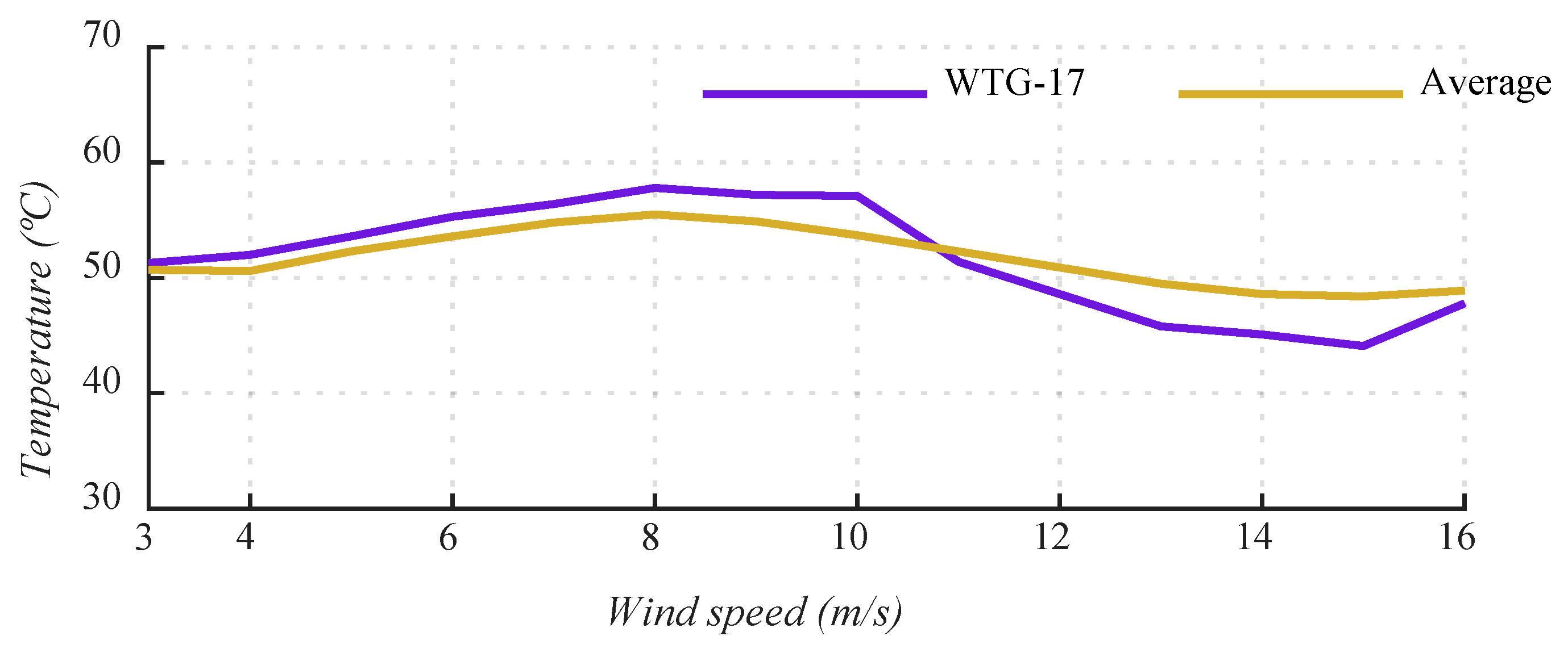
After analyzing this data, two turbines with an increase in temperatures (WTG-17 and WTG-22) and subsequent substitution of the valves were detected. As explained in Section 3.4, in this case, the temperatures of these two turbines were out of range of the average of the other 18. The increase in temperature is due to the incorrect performance of these oil valves.
First case: the defect due to high temperature was detected in November 2015 and the valves were changed in December 2015:
It can be observed that the oil temperature for WTG-17 clearly deviates from the average temperature values before the valve substitution (Figure 14), but it returns to approximate average temperature values when the valve is substituted (Figure 15).
Second case: the defect due to high temperature was detected in February 2016 and the valves were changed at the end of that month.
A similar trend was observed in the case of WTG-22, obtaining a deviation from the oil temperature values before the valve substitution (Figure 16) and a good match when the new valve was installed (Figure 17).
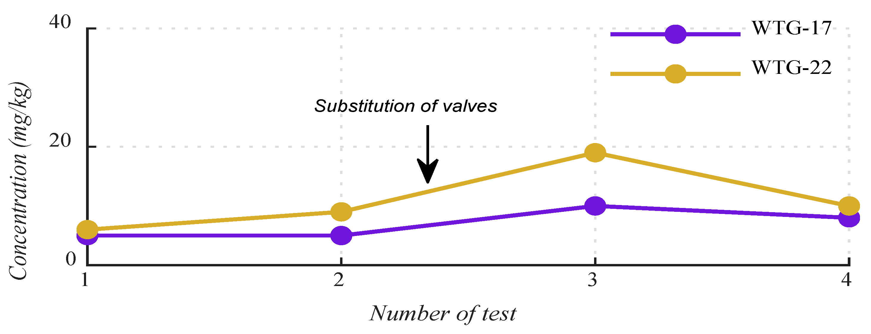
In both cases (WTG-17 and WTG-22), the consequences of the valve substitution in the oil analysis results are relevant increase of wear elements such as zinc (Figure 18) and copper (Figure 19), due to the installation of new pieces with both materials.
Tests 1 and 2 are performed before the valve substitution, test 3 is after the new valve is installed, and test 4 collects data after a filtering process is carried out. It can be observed that the concentration of zinc and copper clearly increases when the new valve is installed due to contamination with the valve materials (test 3), and it decreases to some extent after the filtering process.
The conclusions of these oil analyses could be erroneous (due to lack of information). It is also taken into consideration that these elements showcase bearing wear; thus, new unnecessary actions such as endoscopies or vibration analysis would be required, with associated costs.
4.5. Position of Sample Taking
Two samples of the same oil for the same gearbox with 320 L in a 1.5 MW wind turbine were taken at the same time and analyzed in the same world-renowned laboratory in the second quarter of 2018. A unique difference, however, is the position of the sample, before and after the filter (position 1 and 2, respectively, in Figure 2).
Figure 20 shows that the increase in the three types of particle sizes are: (i) 20% in the case of particles >4 µ; (ii) 33% for >6 µ; and (iii) 7% for >14 µ.
In this case, the filter dirtiness altered the values because in position 2, the particles in the oil are higher than in position 1, and as a consequence of this result, the filter must be checked, cleaned, and even substituted if necessary. In the case where the filter was clean and therefore functioning correctly, that is, cleaning the oil and removing dirt, the opposite will occur, where the number of particles in sample 1 would be less than 2; hence, it is important to always take samples in the same position in order to avoid differences in results.
The extensive results from Figure 3 to Figure 20 show that incomplete information in O&M procedures can lead to erroneous diagnosis. Specifically, five aspects in O&M procedures for the wind turbine gearbox oil were analysed for the first time in this work to verify that:
- (i)
- Oil refilling significatively alters the concentration of additives (e.g., zinc, phosphorus, and sulphur) in the oil analysis results.
- (ii)
- The change in oil brand can lead to false alarms since additives (e.g., molybdenum, magnesium, and zinc) can exceed the allowable limits.
- (iii)
- The installation of an off-line filter highly affects the concentration of wear particles and consequently modifies oil analysis results.
- (iv)
- The replacement of the thermostatic valve alters the values of some additives (e.g., zinc and copper) due to contamination with the valve materials.
- (v)
- The position of the sample taking causes modifications in the concentration of wear particles.
Considering the impact of the five analysed aspects of the gearbox oil O&M procedure on the analytic results, it can be concluded that the diagnosis is sensitive to different aspects of the procedure. In other words, disregarding relevant aspects might lead to erroneous diagnosis, ultimately affecting wind turbine reliability. The degree of sensitivity for each O&M aspect is quantified in this work to help researchers and practitioners in the field of wind energy conversion systems to understand the impact on the analytic results and the importance of carrying out the O&M with complete information.
5. Conclusions
Even though reliability is a main concern in the wind energy industry, operation and maintenance (O&M) procedures are performed in many cases with incomplete information, leading to erroneous diagnosis. In the specific case of the gearbox oil of wind turbines, the results of the oil analysis results can be highly altered by extrinsic phenomena and events. In spite of the importance of predictive maintenance, there is a lack of analysis of the impact of some O&M aspects on the gearbox oil diagnosis.
This study fills this gap by analyzing five relevant aspects of the O&M procedure and quantifying the impact on the analytic results (e.g., wear particles and additive concentration). Specifically, extensive experimental results from wind farms with different location and technologies indicate that the condition of the oils and the results of the oil analysis are affected by different causes:
Improvements in oil condition occur in cases such as: (i) leakage and oil filling, where the intact properties of the new oil lead to an overall increase in oil additives and improve the general condition of the oil; or (ii) the installation of a portable offline filter, which generates a reduction in oil dirt and wear particles.
The results are altered in several situations: (i) when the oil brand is changed, which implies a different chemical composition and proportions of additives (even different additives); in this case, remains of the old oil after cleaning and “flushing” of the gearbox, causing a mixture of these remains with the new oil and therefore a contamination of the new results; or (ii) when the position of the sample taking is different (before or after the filtering), where it is demonstrated that two samples in the same equipment and on the same day, but in different positions, show differences in the results due to the effect of the filter on cleaning of the oil.
Finally, there is a deterioration of the results when the oil works at high temperatures. The most common cause of this event is the degradation in the thermostatic valves, which generates double consequences: (i) high temperatures in the operation; and (ii) replacement of the thermostatic valves themselves, which have iron and copper parts that produce an increase of these elements in the oil.
The quantitative analysis confirms the sensitivity of the oil analysis results to different O&M aspects and informs about the risks that can be assumed when performing gearbox oil maintenance with incomplete information. It is expected that the results and conclusions will help researchers and practitioners in decision-making on the different aspects that should be covered in the O&M of wind turbines gearbox oil.
All these situations can provoke false warnings, which trigger modifications in the operation and maintenance of the wind farm with new unnecessary tasks and costs such as: (i) oil refills; (ii) offline filtering; (iii) new oil samplings; (iv) videoscopes; or (v) vibration analysis. This could take technicians many hours to finish, affecting the production, and thus leading to significant wastage of waste and economic costs.
Without reliable results, the trends of the different analyses would not have any value since they cannot compare the evolution of the different elements (additives, wear particles, viscosity, water, etc.). Therefore, if there is no reliable information that warns of risk situations, no actions can be taken and the propagation of the problem cannot be stopped. In the operation and maintenance strategy of wind farms, predictive and preventive maintenance must prevail over corrective maintenance (programmed substitution of a bearing versus non-programmed substitution of the complete gearbox).
Author Contributions
Data curation, J.R.d.A.; Investigation, J.R.d.A.; Methodology, M.J.D. and F.J.M.; Supervision, M.J.D. and F.J.M.; Writing—original draft, J.R.d.A.; Writing—review & editing, M.J.D. and F.J.M. All authors have read and agreed to the published version of the manuscript.
Funding
This research received no external funding.
Conflicts of Interest
The authors declare no conflict of interest.
References
- Ohlenforst, K.; Sawyer, S.; Dutton, A.; Backwell, B.; Fiestas, R.; Lee, J.; Qiao, L.; Zhao, F.; Balachandan, N. Global Wind Report 2018; Global Wind Energy Council: Brussels, Belgium, April 2019. [Google Scholar]
- Guiot, J.; Cramer, W. Climate change: The 2015 Paris Agreement thresholds and Mediterranean basin ecosystems. Science 2016, 354, 465–468. [Google Scholar] [CrossRef]
- United Nations. Framework Convention on Climate Change. Conference of the Parties; Twenty-First Session. Paris, on 12 December 2015. Available online: https://unfccc.int/resource/bigpicture/index (accessed on 12 September 2019).
- Teng, W.; Zhang, X.; Liu, Y.; Kusiak, A.; Ma, Z. Prognosis of the remaining useful life of bearings in a wind turbine gearbox. Energies 2017, 10, 32. [Google Scholar] [CrossRef] [Green Version]
- Pelajo, J.C.; Brandão, L.E.; Gomes, L.L.; Klotzle, M.C. Wind farm generation forecast and optimal maintenance schedule model. Wind Energy 2019, 22, 1872–1890. [Google Scholar] [CrossRef]
- Carroll, J.; Koukoura, S.; McDonald, A.; Charalambous, A.; Weiss, S.; McArthur, S. Wind turbine gearbox failure and remaining useful life prediction using machine learning techniques. Wind Energy 2019, 22, 360–375. [Google Scholar] [CrossRef] [Green Version]
- Helsen, J.; Peeters, C.; Doro, P.; Ververs, E.; Jordaens, P.J. Wind farm operation and maintenance optimization using big data. In Proceedings of the 2017 IEEE Third International Conference on Big Data Computing Service and Applications (BigDataService), San Francisco, CA, USA, 6–9 April 2017; pp. 179–184. [Google Scholar]
- Aziz, U.; Charbonnier, S.; Bérenguer, C.; Lebranchu, A.; Prevost, F. SCADA data based realistic simulation framework to evaluate environmental impact on performance of wind turbine condition monitoring systems. In Proceedings of the 2019 4th Conference on Control and Fault Tolerant Systems (SysTol), Casablanca, Morocco, 18–20 September 2019; pp. 360–365. [Google Scholar]
- Zhe, H.; Fuchuan, S.; Biao, C. (2012, May) Review and design study of drive train for MW class direct drive wind turbine. In Proceedings of the IEEE PES Innovative Smart Grid Technologies, Tianjin, China, 21–24 May 2012; pp. 1–4. [Google Scholar]
- Márquez, F.P.G.; Tobias, A.M.; Pérez, J.M.P.; Papaelias, M. Condition monitoring of wind turbines: Techniques and methods. Renew. Energy 2012, 46, 169–178. [Google Scholar] [CrossRef]
- Sinha, Y.; Steel, J.A.; Andrawus, J.A.; Gibson, K.J. Significance of Effective Lubrication in Mitigating System Failures—A Wind Turbine Gearbox Case Study. Wind Eng. 2014, 38, 441–449. [Google Scholar] [CrossRef]
- Coronado, D.; Wenske, J. Monitoring the Oil of Wind-Turbine Gearboxes: Main Degradation Indicators and Detection Methods. Machines 2018, 6, 25. [Google Scholar] [CrossRef] [Green Version]
- Sheng, S. Monitoring of Wind Turbine Gearbox Condition through Oil and Wear Debris Analysis: A Full-Scale Testing Perspective. Tribol. Trans. 2016, 59, 149–162. [Google Scholar] [CrossRef]
- Manyala, J.O.; Atashbar, M.Z. Development of particle contaminants monitor system for gearbox lubricant prognostics. In Proceedings of the 2016 IEEE SENSORS, Orlando, FL, USA, 30 October–3 November 2016; pp. 1–3. [Google Scholar]
- Raza, A.; Ulansky, V. Optimal Preventive Maintenance of Wind Turbine Components with Imperfect Continuous Condition Monitoring. Energies 2019, 12, 3801. [Google Scholar] [CrossRef] [Green Version]
- Junior, V.L.; Zhou, J.; Roshanmanesh, S.; Hayati, F.; Hajiabady, S.; Li, X.Y.; Dong, H.; Papaelias, M. Evaluation of damage mechanics of industrial wind turbine gearboxes. Insight-Non-Destr. Test. Cond. Monit. 2017, 59, 410–414. [Google Scholar] [CrossRef] [Green Version]
- Ragheb, A.; Ragheb, M. Wind turbine gearbox technologies. In Proceedings of the 2010 1st International Nuclear and Renewable Energy Conference (INREC’10), Amman, Jordan, 21–24 March 2010. [Google Scholar]
- Sequeira, C.; Pacheco, A.; Galego, P.; Gorbeña, E. Analysis of the efficiency of wind turbine gearboxes using the temperature variable. Renew. Energy 2019, 135, 465–472. [Google Scholar] [CrossRef]
- Ismon, M.; Zaman, I.; Ghazali, M.I. Condition Monitoring of Variable Speed Worm Gearbox Lubricated with Different Viscosity Oils. Appl. Mech. Mater. 2015, 773–774, 178–182. [Google Scholar] [CrossRef] [Green Version]
- De Azevedo, H.D.M.; Araújo, A.M.; Bouchonneau, N. A review of wind turbine bearing condition monitoring: State of the art and challenges. Renew. Sustain. Energy Rev. 2016, 56, 368–379. [Google Scholar] [CrossRef]
- Wright, J. Understanding Filter Efficiency and Beta Ratios. Web Machinery Lubrication. 2008. Available online: https://www.machinerylubrication.com/Read/1289/oil-filter-efficiency (accessed on 21 December 2018).
- ISO 4406: 1999 Hydraulic Fluid Power—Fluids—Method for Coding the Level of Contamination by Solid Particles; International Organization for Standardization: Geneva, Switzerland, 1999.
- Sessler, D.I. Temperature monitoring and perioperative thermoregulation. Anesthesiol. J. Am. Soc. Anesthesiol. 2008, 109, 318–338. [Google Scholar] [CrossRef] [PubMed] [Green Version]
- Manwell, J.F.; McGowan, J.G.; Rogers, A.L. Wind Energy Explained: Theory, Design and Application; John Wiley and Sons: Chichester, West Sussex, UK, 2010. [Google Scholar]
- Gould, B.; Demas, N.; Pollard, G.; Rydel, J.; Ingram, M.; Greco, A. The Effect of Lubricant Composition on White Etching Crack Failures. Tribol. Lett. 2019, 67, 7. [Google Scholar] [CrossRef]
- Zhang, M.; Yuan Liao, Z.; Farooq, K. Cleanliness control and management of gearbox lubrication system in wind turbine generator. J. Renew. Sustain. Energy 2013, 5, 21419. [Google Scholar] [CrossRef]
Figure 1.
Gearbox offline oil filtration.

Figure 2.
Sampling position options: option (1) when the sampling is done before the oil filter system, and option (2) when the sampling is performed after the oil filter system.
Figure 2.
Sampling position options: option (1) when the sampling is done before the oil filter system, and option (2) when the sampling is performed after the oil filter system.

Figure 3.
Results of the effects of the refill on additive zinc in a gearbox, comparing the theoretical trend (without refilling) and the real trend.
Figure 3.
Results of the effects of the refill on additive zinc in a gearbox, comparing the theoretical trend (without refilling) and the real trend.

Figure 4.
Results of the effects of the refill on additive Phosphorus in a gearbox comparing the theoretical trend (without refilling) and the real trend.
Figure 4.
Results of the effects of the refill on additive Phosphorus in a gearbox comparing the theoretical trend (without refilling) and the real trend.

Figure 5.
Results of the effects of the refill on additive Sulphur in a gearbox comparing the theoretical trend (without refilling) and the real trend.
Figure 5.
Results of the effects of the refill on additive Sulphur in a gearbox comparing the theoretical trend (without refilling) and the real trend.

Figure 6.
Evolution after oil brand substitution; Mg evolution.

Figure 7.
Evolution after oil brand substitution; Zn evolution.

Figure 8.
Evolution after oil brand substitution; Mo evolution.

Figure 9.
Comparison of particles >4 µ before and after offline filtering.

Figure 10.
Comparison of particles >6 µ before and after offline filtering.

Figure 11.
Comparison of particles >14 µ before and after offline filtering.

Figure 12.
Effects of filtering on oil contamination (average)—number of particles (ISO 4406/99).

Figure 13.
Evolution after filtering.

Figure 14.
Oil gearbox temperature—November 2015.

Figure 15.
Oil gearbox temperature—December 2015.

Figure 16.
Oil gearbox temperature—February 2016.

Figure 17.
Oil gearbox temperature—March 2016.

Figure 18.
Substitution of valves—zinc evolution.

Figure 19.
Substitution of valves—copper evolution.

Figure 20.
Results from different sample taking positions in the particles (in 100 mL; ISO 4406/99).
Figure 20.
Results from different sample taking positions in the particles (in 100 mL; ISO 4406/99).


Table 1.
Standard parameters used in the gearbox oil analysis.
| Oil Condition | Additives | Wear Elements | Contaminant Elements |
|---|---|---|---|
| Viscosity at 40 °C Particle counting ISO Code (4/6/14) PQ Index Acidity Water Appearance Nitration Oxidation | Barium Calcium Magnesium Phosphorus Zinc | Aluminum Chrome Copper Iron Molybdenum Nickel Lead Tin Silver | Boron Potassium Sodium Silicon |
Table 2.
Excerpt from international standard ISO 4406:1999 code that establishes the relationship between particle counts and oil contamination (quantifying levels of particulate contamination of fluid per milliliter in three sizes: 4 μ, 6 μ, and 14 μ and coding the contamination level with three numbers (example: 17/15/12).
| ISO 4406/99 | ||
|---|---|---|
| Max. Number of Particle/100 mL | ||
| From | To | Class |
| --- | --- | --- |
| 250,000 | 500,000 | 19 |
| 130,000 | 250,000 | 18 |
| 64,000 | 130,000 | 17 |
| 32,000 | 64,000 | 16 |
| 16,000 | 32,000 | 15 |
| 8000 | 16,000 | 14 |
| --- | --- | --- |
Table 3.
Danger limits of the additives, depending on the oil brand defined by the manufactures, with respect to chemical composition.
Table 3.
Danger limits of the additives, depending on the oil brand defined by the manufactures, with respect to chemical composition.
| Oil Brand | Danger (Oil Change) | ||
|---|---|---|---|
| Mg (mg/kg) | Zn (mg/kg) | Mo (mg/kg) | |
| Oil 1 | >3000 | >3000 | >2500 |
| Oil 2 | >20 | >20 | >20 |
| Oil 2 flushing | >150 | >150 | >100 |
© 2020 by the authors. Licensee MDPI, Basel, Switzerland. This article is an open access article distributed under the terms and conditions of the Creative Commons Attribution (CC BY) license (http://creativecommons.org/licenses/by/4.0/).
Share and Cite
MDPI and ACS Style
del Álamo, J.R.; Duran, M.J.; Muñoz, F.J. Analysis of the Gearbox Oil Maintenance Procedures in Wind Energy. Energies 2020, 13, 3414. https://0-doi-org.brum.beds.ac.uk/10.3390/en13133414
AMA Style
del Álamo JR, Duran MJ, Muñoz FJ. Analysis of the Gearbox Oil Maintenance Procedures in Wind Energy. Energies. 2020; 13(13):3414. https://0-doi-org.brum.beds.ac.uk/10.3390/en13133414
Chicago/Turabian Styledel Álamo, José Ramón, Mario J. Duran, and Francisco J. Muñoz. 2020. "Analysis of the Gearbox Oil Maintenance Procedures in Wind Energy" Energies 13, no. 13: 3414. https://0-doi-org.brum.beds.ac.uk/10.3390/en13133414
Note that from the first issue of 2016, this journal uses article numbers instead of page numbers. See further details here.