Article

Optimal Design of High-Power Medium-Frequency Transformer Using Hollow Conductors with Consideration of Multi-Objective Parameters

1
College of Electrical Engineering, Nantong University, Nantong 226019, China
2
Nantong Research Institute for Advanced Communication Technologies, Nantong 226019, China
*
Author to whom correspondence should be addressed.
Submission received: 16 June 2020 / Revised: 12 July 2020 / Accepted: 13 July 2020 / Published: 15 July 2020

Abstract

:
A power electronic transformer (PET) is applied to the high-speed train for lightweight demand. A 300 kW/5 kHz high-power medium-frequency transformer (HPMFT) using hollow conductors in a power unit of the PET is optimally designed in this paper. The target of the design is to balance the loss, leakage inductance, and weight of the HPMFT. For this purpose, the design parameters of the HPMFT are firstly confirmed according to the system structure and parameters of the PET. Secondly, the design process of HPMFT is developed. Finally, the results of 48 design schemes of core-type and shell-type structures are compared by the comprehensive evaluation standard, which equilibrates the three above objective parameters of the HPMFT. According to the optimal scheme, a prototype is manufactured, whose test results verify the correctness of the optimal design method.

1. Introduction

The power electronic transformer (PET), also known as the solid-state transformer, is a new type of intelligent transformer that combines power electronic transformation technology with the electromagnetic induction principle to realize the transformation of electric energy form [1]. PET has excellent control performance while completing the tasks of electrical isolation and voltage change, which makes it a good application prospect in the fields of smart power grid and energy internet [2,3]. In addition, the operation frequency of the transformer is increased through the power electronic control, which greatly reduces the volume and weight of the transformer, making the PETs also suitable for offshore wind farms, electric locomotives, and other applications with high restrictions on the volume and weight of the transformer [4,5,6].
The high-power medium-frequency transformer (HPMFT) is a key component of the PET, which plays the role of electrical isolation and voltage transformation [7]. Due to the higher electromagnetic coupling frequency and the connection between the windings and the power electronic converters, the design method of the HPMFT is quite different from that of the traditional power frequency transformer. The smaller volume and higher frequency can increase the energy density of the transformer. However, the loss density also increases greatly. The decreased volume makes the insulation and heat dissipation more important in the optimal design process of the HPMFT [8,9].
The loss of the HPMFT mainly includes winding loss and core loss. The skin and proximity effect brought by the eddy current at high frequency makes the current density distribution in the windings uneven and concentrated on the surface of the conductor. Foils, litz wires, and hollow conductors are often used to reduce the thickness of the conductors while ensuring sufficient cross-sectional area, so as to reduce high-frequency winding loss [10,11]. Hollow conductors have both high material utilization rate and heat dissipation efficiency, which is an ideal choice for the HPMFT [12].
The core loss will also increase significantly with the increase of the frequency. Ultra-thin silicon steel sheet, ferrite, amorphous, and nanocrystalline materials are often used to manufacture the core of the HPMFT to reduce the high-frequency core loss [13]. Nanocrystalline has a small loss density at high frequency and a relatively high saturation magnetic density, which is most commonly used in the HPMFT. Moreover, the voltage and current waveforms of the HPMFT are often non-sinusoidal after the power electronic transformation, which should be considered in the calculation of the winding and core loss [14,15].
In the PET, the distributed parameters of the HPMFT, as a part of the converter circuit, will affect the converting state of the power electronic devices. When the phase-shift control is adopted, the leakage inductance of the HPMFT must reach a certain value to meet the soft switching criteria of the power electronic devices. When resonance control is adopted, the leakage inductance of the HPMFT needs to match with the resonance capacitance and frequency, so that the circuit can achieve the ideal resonance state [16,17]. Therefore, in the design stage, the value of the leakage inductance should be considered according to the control mode.
In recent years, some researchers have carried out optimal design research on the HPMFTs for different applications [18,19,20,21,22]. In these cases, different types of windings, cores, and structures are used in different power levels. The winding forms of these studies are mainly solid conductors, litz wires, and foils. When selecting the optimal design scheme, multiple objective parameters are not comprehensively taken into account.
The aim of this paper is to optimize the design of a 300 kW/5 kHz HPMFT in a power unit of the PET based on the lightweight demand. The contributions of the paper can be concluded as follows: (1) A comprehensive evaluation coefficient is established to choose the optimal design scheme, which balances the loss, leakage inductance, and weight of the HPMFT. (2) The hollow conductors are adopted in this design case for a high material utilization rate of the winding material and heat dissipation efficiency of the HPMFT. This kind of winding form is rarely used in the former design cases. (3) Both core-type and shell-type structures are taken into account in this design case, whereas usually one kind of transformer structure is considered in the previous cases.
This paper is organized as follows. Section 2 presents the system structure of the PET and the corresponding design parameters of the HPMFT. The design process of the HPMFT is demonstrated in Section 3. In Section 4, the design results are evaluated. Section 5 conducts the experimental validation of the HPMFT prototype, and Section 6 gives the conclusion.

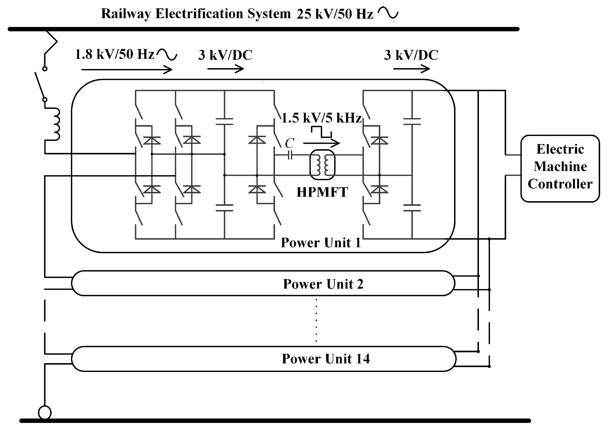
2. System Structure of PET and Design Parameters of HPMFT
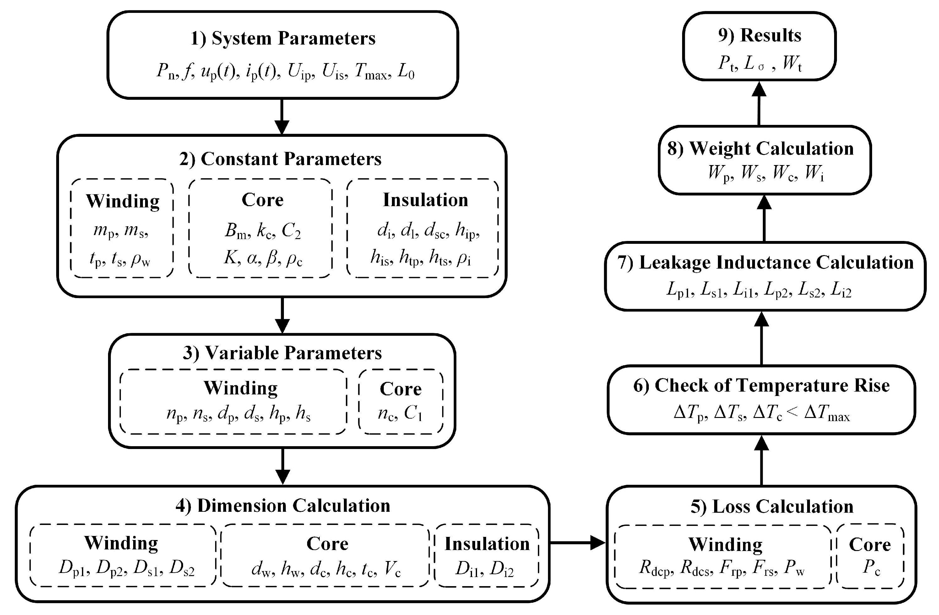
Due to the limitation of the voltage endurance and current passing capability of the power electronic devices, PET adopts the series-parallel mode of multiple power units to achieve the required voltage and power level. Figure 1 shows the system structure of a 3.3 MW PET, which is intended to be applied in the high-speed train for lightweight demand. The PET includes 14 power units, and the structure of each power unit is the same. On the primary side, the PET is directly connected with the railway electrification system, and each power unit is connected in series. On the secondary side, the PET is connected with the electric machine controller, and each power unit is connected in parallel. The voltage and frequency of each part in power unit 1 are also presented in Figure 1.
The bidirectional DC/DC converter in the power unit is supposed to adopt the control mode of series resonance. With this mode, the converter transmits power through a resonant loop composed of the resonant capacitor and the leakage inductance of the HPMFT. Taking the switching losses of the power electronic devices into account, the frequency of the converter, f = 5 kHz. Taking both the leakage inductance value region of the former HPMFT design cases and the frequency of the converter into account, the matched resonant capacitor, C = 85 μF. According to the relationship between the value of the resonant capacitor and the leakage inductance of the HPMFT:
ω L 0 = 1 ω C
where w is the corresponding angular frequency. According to Equation (1), the expected leakage inductance of the HPMFT L0 = 12 μH.
Both sides of the bidirectional DC/DC converter adopt a half-bridge structure, the DC voltage is UDC = 3 kV. As a result, the square wave voltage amplitude of the primary winding of the HPMFT is Upm = UDC/2 = 1.5 kV. The turn ratio and the maximum allowable temperature rise of the HPMFT are 1:1 and 70 °C, respectively. The design parameters of the HPMFT are presented in Table 1.
According to the relative position of the winding and the core, the structure of the transformer is mainly divided into three kinds: core type, shell type, and matrix type. The winding and insulation structures of the core-type transformer are easy to assemble. The shell-type transformer has better mechanical and heat dissipation performance than the core type. The matrix-type transformer seems to combine the advantages of core type and shell type, but its defects are as follows: the structure is complex due to the use of multiple cores, which means the volume, weight, and cost of the transformer are high. Besides that, the primary and secondary windings are wound on different arms of the core, which makes the leakage inductance of the transformer large, so the matrix type is not suitable to be used in the high-power power electronic conversion circuit.
In addition to the three main structures mentioned above, there is still a kind of transformer using coaxial cables, whose outer and inner layers are the primary and secondary windings of the transformer, respectively. The leakage inductance of the transformer is small because of the structure, but its current-carrying capacity is limited, which makes it only suitable for the low-power application. According to the design parameters and application conditions of the HPMFT, the core-type and shell-type structures are adopted in this study.

3. Design Process

The parameters and structures of the HPMFT are confirmed according to the application conditions. In addition, the size of the nanocrystalline core and hollow conductor that can be customized are surveyed. The design process of the HPMFT is developed, as shown in Figure 2.

3.1. Constant Parameters

The structure design of the core-type and shell-type HPMFTs are respectively presented in Figure 3 and Figure 4. Following the above process, the design works are conducted for these two types of HPMFT by using the same hollow conductors and nanocrystalline core materials. Through the comparison of the design results by a comprehensive evaluation coefficient, which is presented in Section 4, the optimal design scheme of the HPMFT is chosen.
The relationship between the root mean square (RMS) value of the voltage on the primary side of the HPMFT Up, the frequency f, and the amplitude of the flux density Bm is presented in Equation (2).
U p = k f k c f m p n p B m S
where kf is the waveform coefficient of the primary side voltage, kc is the lamination coefficient of the core, mp is the number of layers of the primary winding, np is the number of turns in each layer of the primary winding, and S is the cross-sectional area of the core. When series resonance control is adopted, the waveform of the voltage on the primary side of the transformer is square. As a result, the RMS value of the voltage is equal to the amplitude, Up = Upm = 1.5 kV, and the waveform coefficient of the square wave voltage is kf = 4.

3.1.1. Constant Parameters of the Winding

Both in the core-type and shell-type design schemes, the primary and secondary windings are two-layer structures, mp = ms = 2, and the number of turns in each layer is np and ns, respectively. Since the turn ratio of the HPMFT is 1:1, thus np = ns.
In order to reduce the leakage inductance and winding loss of the HPMFT, the cross transposition of the windings is adopted. For the core-type design scheme, the two layers of the primary and secondary windings, whose ends are connected, are respectively located on the two arms of the core. For the shell-type design scheme, the two layers of the secondary winding are on the two sides of the primary winding, the two layers of the primary and secondary windings are also connected through the ends.
In order to enhance the heat dissipation of the winding, the primary and the secondary windings adopt the rectangular hollow copper conductor, which is cooled by the circulating deionized water. The skin depth of the copper material at 5 kHz is δcu = 0.94 mm. The thickness of the conductor adopts 1.6 times of the skin depth, which is tp = ts = 1.5 mm, according to the conclusions of a large number of the finite element analysis [23]. The density of the copper conductor is ρw = 8.9 × 10³ kg/m3.

3.1.2. Constant Parameters of the Core

Due to the limited width of the nanocrystalline strip produced at the current manufacturing level, the cores of the HPMFT are spliced by nc and 2nc sub-cores in the core-type and the shell-type design scheme, respectively. The core is winded by the 40 mm wide nanocrystalline strip provided by AT&M (Beijing, China), so the thickness of the single-core is C2 = 40 mm. Strip winding thickness determines the width of the core arm C1. For the design schemes of core-type and shell-type HPMFTs, the sectional areas of the core, S, are as follows, respectively:
S = C 1 C 2 n c
S = 2 C 1 C 2 n c
The lamination coefficient of the core is kc = 0.8. Considering that no additional radiators are installed on the core, the amplitude of the flux density is Bm = 0.7 T. Since the manufacturer did not provide the core loss density values of the core at different frequencies, the coefficients of the original Steinmetz equation (OSE) for the core in the 1–10 kHz band were fitted through the core loss tests of an HPMFT assembled with the same nanocrystalline core in the laboratory. The equation of OSE [24] is:
P v = K f α B m β
where Pv is the core loss density. When the units of Pv, f, and Bm are W/kg, kHz, and T respectively, the coefficients of OSE are K = 9.58, α = 1.32, and β = 1.58. The density of the nanocrystalline core is ρc = 7.2 × 10³ kg/m3.

3.1.3. Constant Parameters of the Insulation Distance

As mentioned above, the insulation level of the primary side of the HPMFT should be considered according to the system voltage. According to railway power system standard, the main insulation withstand power frequency voltage of the transformer is 60 kV, and the impulse voltage is 150 kV. The electric field simulations for the finite element models of the HPMFT are carried out to verify the main insulation distance under the above insulation requirements. The minimum main insulation distance between the primary and secondary winding is di = 10 mm, and the minimum distance between the primary winding and the core is hip = 14 mm.
In addition, according to the insulation design experience of the transformer, other insulation distance parameters in the design schemes are evaluated. The insulation distance between the layers of the primary winding is dl = 5 mm, the insulation distance between the secondary winding and the core is dsc = 3 mm, the insulation distance at the end of secondary winding is his = 5 mm, and the insulation distance between the turns of the primary and secondary winding is htp = hts = 1 mm. The density of the insulation materials is ρi = 2.3 × 10³ kg/m3.

3.2. Variable Parameters

By substituting the constant parameters into Equation (2), the constraint relations among variable parameters np, nc, and C1 in the core-type and shell-type design schemes can be obtained, which are shown in Equations (6) and (7), respectively.
n p n c C 1 = 1.68
n p n c C 1 = 0.84
As the end insulation distance of the primary winding is greater than that of the secondary winding, in order to make full use of the window space of the core, the rectangular hollow conductors are placed horizontally on the primary side and longitudinally on the secondary side. Through the height difference of the single-layer winding, a larger end insulation distance of the primary winding can be obtained. The width and height of the primary winding are dp and hp respectively, and of the secondary winding are ds and hs. Thus, dp = hs, and hp = ds.
There are two sizes of the rectangular hollow copper conductor that can be chosen, which are 12 × 10 mm and 10 × 8 mm, then dp and ds have two value choices. Since the difference of length and width of the conductor is 2 mm, and the difference of end insulation distance between the primary and secondary windings is 9 mm, the minimum value of np is 5. Limited by the requirements of the customized core made by the manufacturer, the range of C1 is 30–60 mm, and the interval is 5 mm.
According to the design schemes of the core-type and shell-type HPMFTs, the variable parameters np, nc, C1, dp, and ds are scanned according to Equations (6) and (7) and the restrictions of the winding and core. Twenty-four sets of the variable parameter values are taken for both the core-type and shell-type schemes, which are presented in Appendix A.

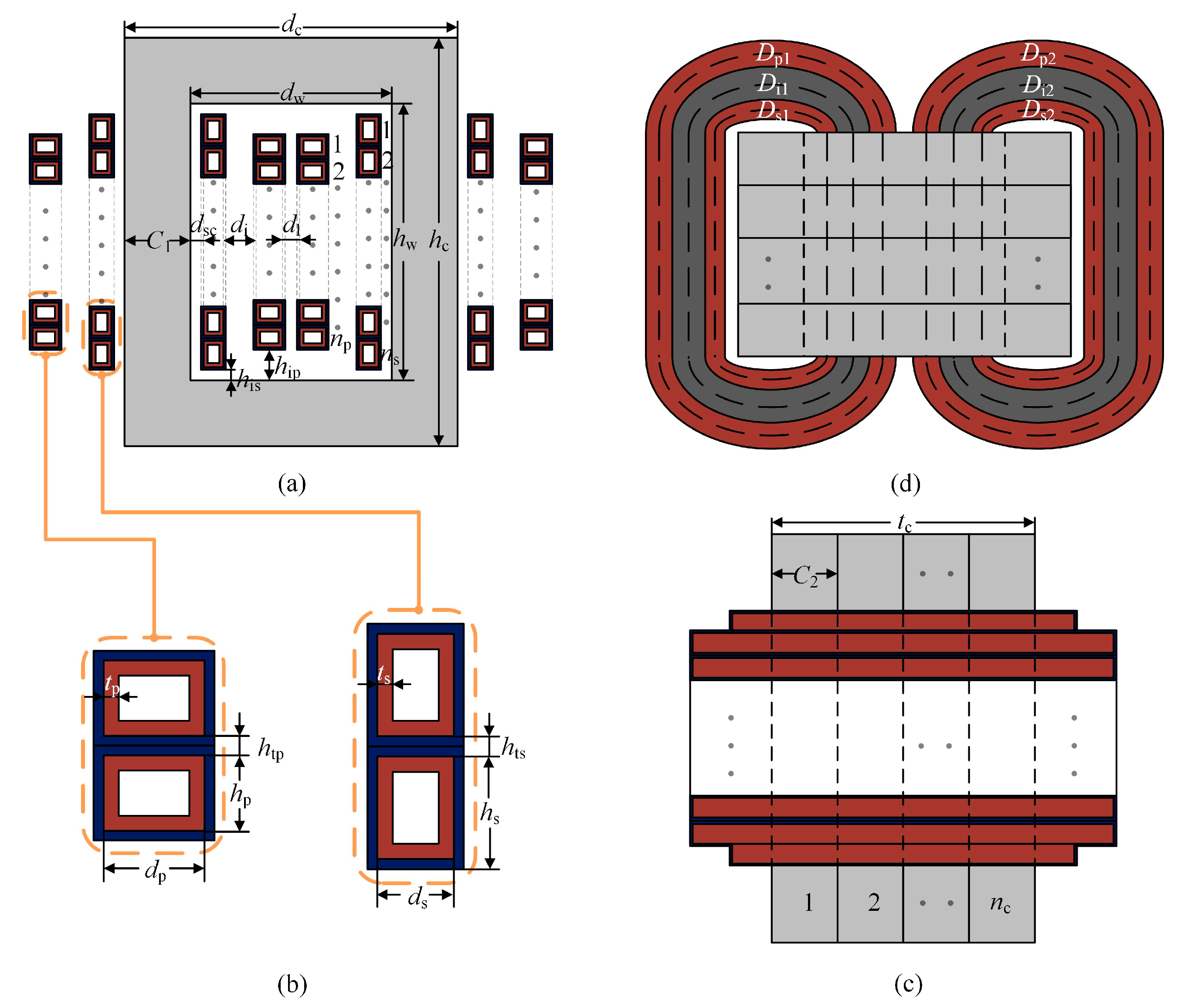
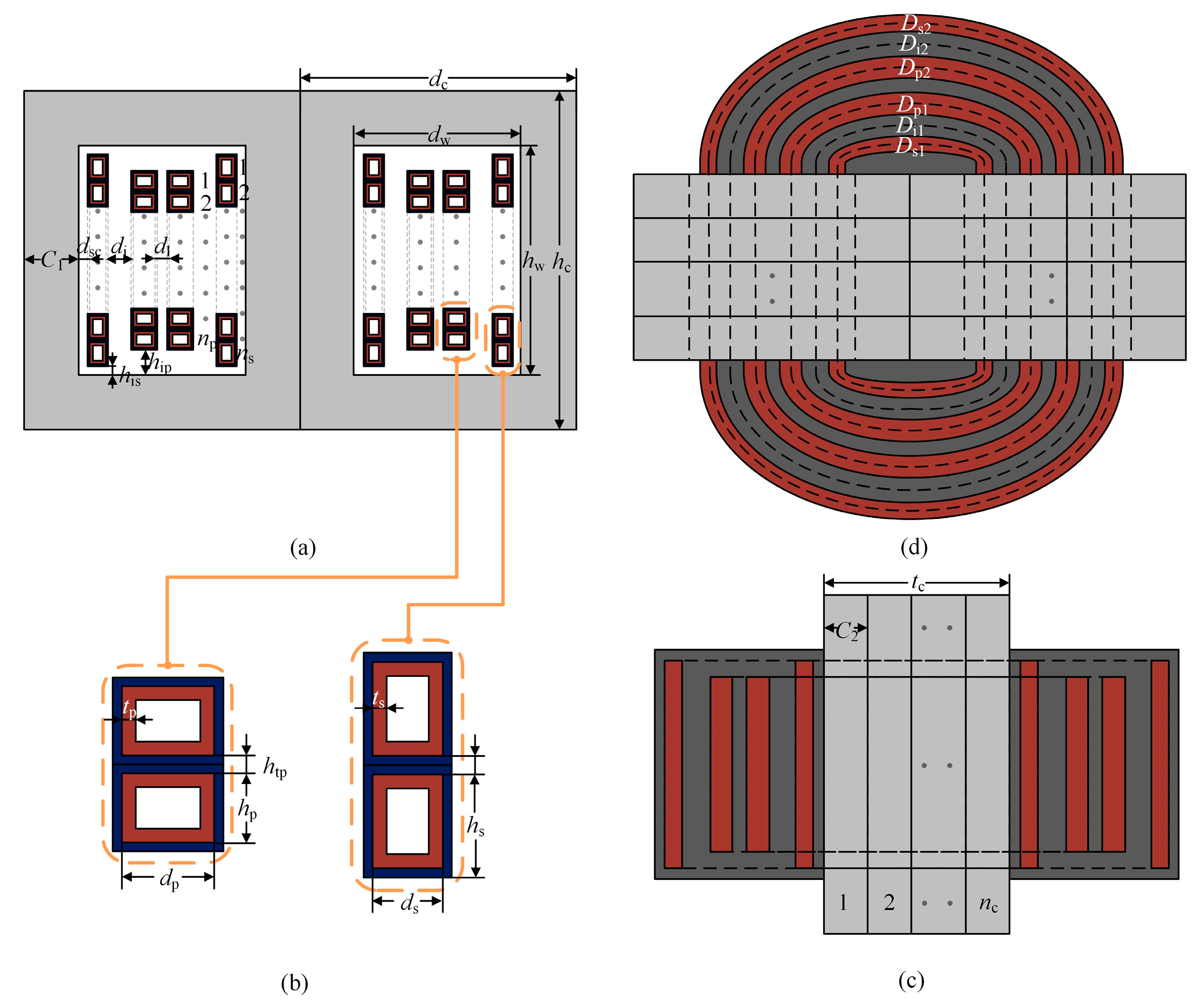
3.3. Dimensions Calculation

According to the structure diagrams of the HPMFT, the equations of relevant dimensions of the winding, core, and insulation can be deduced, ignoring the radians of the windings and insulating layers outside the core. The results of the core-type and shell-type schemes are respectively presented in Appendix B.
For the winding dimensions, Dp1 and Dp2 are the average turn length of the first and second layer of the primary winding respectively, and Ds1 and Ds2 are the average turn length of the first and second layer of the secondary winding, respectively. For the core dimensions, dw and hw are the width and height of the core window respectively, and dc, hc, tc, and Vc are the width, height, thickness, and volume of the core, respectively. For the insulations, Di1 and Di2 are the average length of the first and second insulating layer, respectively.

3.4. Loss Calculation

3.4.1. Winding Loss Calculation

According to the winding dimensions and the research results in Reference [23], the winding loss of each design scheme can be calculated. The DC resistance of the solid conductors with the same outer diameter of the hollow conductors on the primary and secondary side of the transformer are Rdcp and Rdcs, respectively.
R dcp = n p ( D p 1 + D p 2 ) σ cu d p h p
R dcs = n s ( D s 1 + D s 2 ) σ cu d s h s
where the conductivity of copper is σcu = 5.688 × 10⁷ S/m.
The permeability of the solid conductors with the same outer diameter of the hollow conductors on the primary and secondary side of the transformer are Δps and Δss, respectively.
Δ ps = η p d p δ cu
Δ ss = η s d s δ cu
where the skin depth of copper is δcu = 0.94 mm, when the frequency is 5 kHz. ηP and ηS are the porosity coefficients of the primary and secondary windings, respectively. The alternating current (AC) resistivity of the primary and secondary windings are Frp and Frs, respectively.
F rp = Δ ps 3 ( 2 m p 1 2 + 1 ) F h
F rs = Δ ss 3 ( 2 m s 1 2 + 1 ) F h
When the frequency, f = 5 kHz and the thickness of copper hollow conductor is tp = ts = 1.5 mm, the hollow AC resistivity is Fh = 0.968. Since both the core-type and shell-type schemes adopt the winding cross transposition technique, the two layers of both the primary and secondary windings can be regarded as two independent single-layer windings. Thus, the number of the layer of the winding in Equations (12) and (13) is mp1 = ms1 = 1.
The current waveform of the HPMFT is a sine-wave when series resonance control is adopted. Because the turn ratio of the HPMFT is 1:1, the RMS value of the current on the primary and secondary side is equal, Ip = Is. The total winding loss, Pw, of the HPMFT is presented in Equation (14).
P w = I p 2 F rp R dcp + I s 2 F rs R dcs

3.4.2. Core Loss Calculation

Waveform coefficient Steinmetz Equation (WcSE) [15] is one of the most accurate methods to calculate the core loss when the waveform of the excitation voltage is non-sinusoidal, which is achieved through multiplying the waveform coefficient Fws by OSE. When series resonance control is adopted, the terminal voltage of the HPMFT is a square wave, whose Fws = π/4. The core loss Pc of the HPMFT is shown in Equation (15).
P c = F ws K f α B m β ρ c V c
Ignoring the loss of the insulating medium, the total loss of the HPMF, Pt, is as follows:
P t = P w + P c

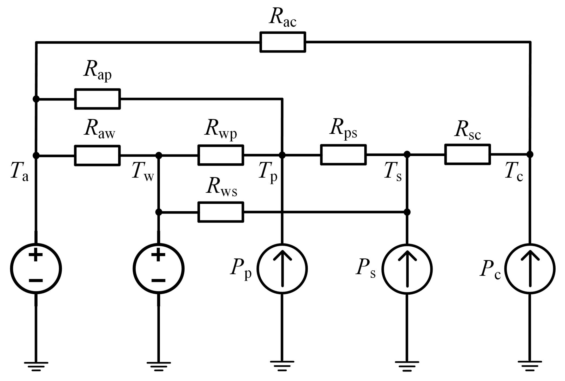
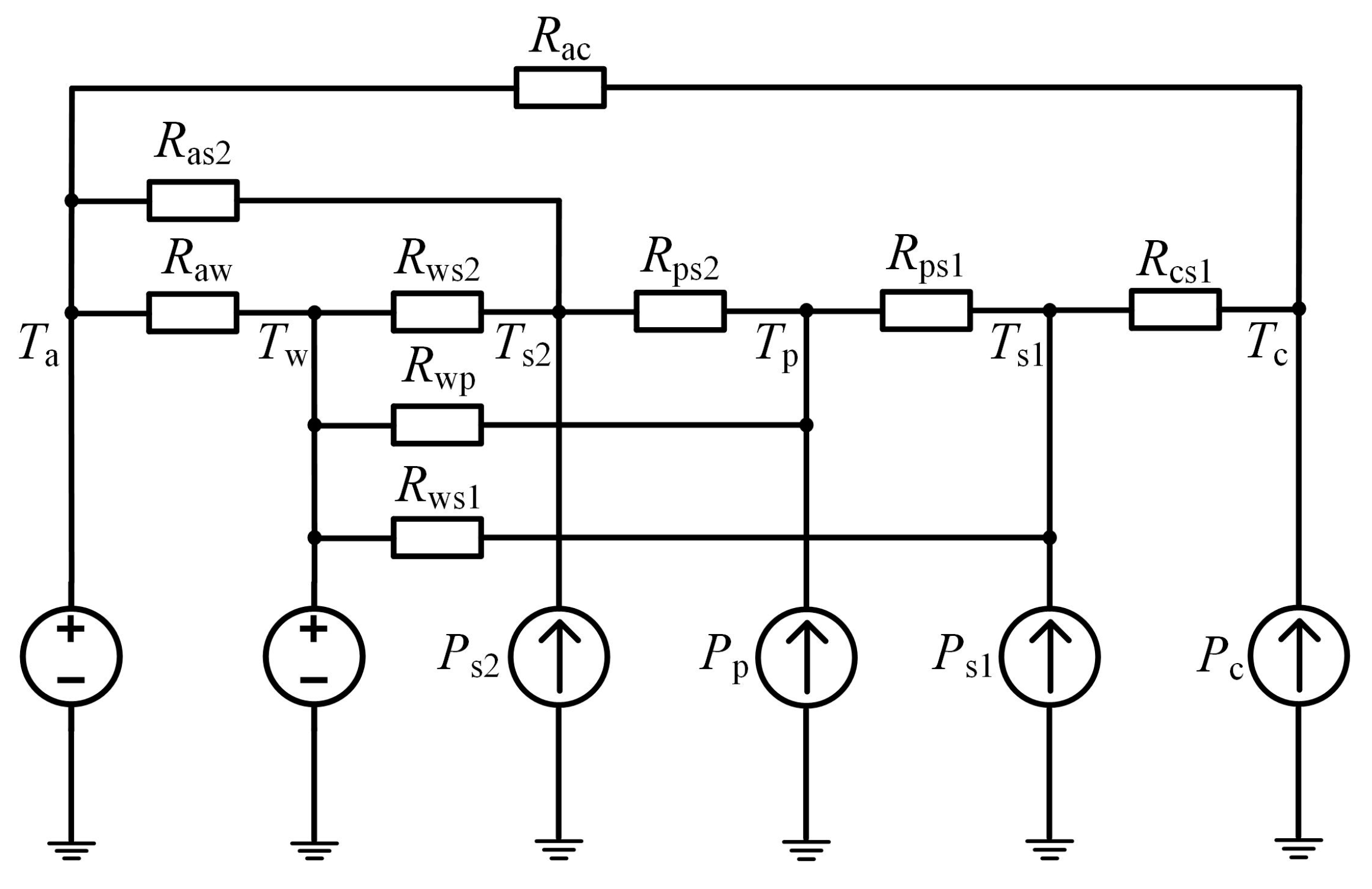
3.5. Check of Temperature Rise

When the winding and core losses of the HPMFT are known, the thermal model of the transformer can be determined according to the design structure and heat dissipation mode, thus the temperature rise of each part of the HPMFT can be verified. When the heat source and thermal resistance are compared with the power source and electric resistance, the thermal model of the transformer can be analyzed by the theoretical method similar to the electric circuit model.
There are three types of heat transfer modes: heat conduction, heat convection, and heat radiation. According to the temperature field characteristics of the HPMFT, the forms of heat conduction and heat convection are mainly considered.
Heat conduction is a transfer of heat moving from the part with the higher temperature to the part with the lower temperature. In the temperature model of the HPMFT, the model of heat transfer between windings, winding, and core is mainly heat conduction. The corresponding thermal resistance, Rt, of heat conduction mode is as follows:
R t = l t λ t A t
where lt and At are the distance and cross-sectional area in the heat transfer direction respectively, and λt is the thermal conductivity of the heat transfer medium.
Heat convection is a heat transfer mode in which heat travels from one part of the space to another through a fluid medium. In the temperature model of the HPMFT, the air and cooling water are the fluid heat dissipation medium, and the heat transfer mode between air and core, air and winding, and winding and cooling water is mainly heat convection. The corresponding thermal resistance, Rw, of the heat convection mode is as follows:
R w = l w N u λ w A w
where lw and Aw are the characteristic length and area of the heat transfer surface respectively, λw is the thermal conductivity of the fluid medium, and Nu is the Nusselt number.
According to the structure design of the core-type HPMFT, the steady-state thermal model is established, as shown in Figure 5. Assuming that the windings and the core are heated uniformly, the heat of the primary winding is dissipated through the thermal convection with the cooling water and air, and heat conduction with the secondary winding. The thermal resistances corresponding to the above heat transfer paths are Rwp, Rap, and Rps, respectively. The secondary winding has only tiny contact surfaces with the air, so the thermal convection between them is ignored. In addition to the heat conduction between the secondary and primary windings, the secondary winding also dissipates heat through the heat convection with the cooling water and the heat conduction with the core, and the heat resistances of the corresponding heat transfer paths are Rws and Rsc, respectively. The core and cooling water dissipate the heat through the heat convection with the air, and the heat resistances of these two heat transfer paths are Rac and Raw, respectively. The power losses of the primary winding, secondary winding, and the core are Pp, Ps, and Pc, respectively. The steady temperature of the air, cooling water, primary winding, secondary winding, and the core are Ta, Tw, Tp, Ts, and Tc, respectively.
According to the structure design of the shell-type HPMFT, the steady-state thermal model is established, as shown in Figure 6. As the primary winding and the first layer of the secondary winding have only tiny contact surfaces with the air, the thermal convection between them and the air can also be ignored. The heat of the second layer of the secondary winding is dissipated through the thermal convection with the cooling water and air, and heat conduction with the primary winding. The thermal resistances corresponding to the above heat transfer paths are Rws2, Ras2, and Rps2, respectively. The primary winding dissipates heat through the heat convection with the cooling water and the heat conduction with the first layer of the secondary winding, and the heat resistances of the corresponding heat transfer paths are Rwp and Rps1, respectively. The first layer of the secondary winding dissipates heat through the thermal convection with the cooling water and the heat conduction with the core, and the heat resistances of the corresponding heat transfer paths are Rws1 and Rcs1, respectively. Rac, Raw, Pp, Pc, Ta, Tw, Tp, and Tc have the same definition as the model of the core-type. The power losses and the steady temperature of the first and second layer of the secondary winding are Ps1, Ps2, Ts1, and Ts2, respectively.
According to the core-type and shell-type steady-state thermal models, the steady temperature of each node can be obtained by solving the equations of the temperature nodes, then the temperature rise of each design scheme can be verified.

3.6. Leakage Inductance Calculation

The leakage inductance of the HPMFT can be calculated by regions according to the distribution characteristics of the leakage magnetic field in the core window. Since the winding cross transposition technique is adopted in both the core-type and shell-type schemes, the two layers of both the primary and secondary windings can be regarded as two independent single-layer windings when calculating the leakage inductance.
Except for the core, the permeability of other parts of the HPMFT is considered as μ = 4π × 10−7 H/m. The width of the leakage magnetic field, λ, is composed of the single-layer windings and the main insulating layer, which is presented in Equation (19).
λ = d p + d s + d i
In the design scheme, the height of the primary and secondary winding is not equal. When calculating the height of the leakage field, the average height of the primary and secondary windings is taken as the height of the windings hw.
h w = 1 2 [ n p h p + n s h s + ( n p 1 ) h tp + ( n s 1 ) h ts ]
In order to compensate the magnetic potential drop outside the core window, the height of the leakage magnetic field is corrected by the coefficient ρ. The definitions of the coefficient ρ and the corrected height h are respectively shown in Equations (21) and (22).
ρ = 1 λ π h w
h = h w ρ = π h w 2 π h w λ
The equations of leakage inductance corresponding to different regions of the core window are presented in Table 2.
In the equations, Frp and Frs are the operators, whose equations are shown as bellow:
F rp = sinh ( 2 Δ ps ) sin ( 2 Δ ps ) cosh ( 2 Δ ps ) cos ( 2 Δ ps )
F rs = sinh ( 2 Δ ss ) sin ( 2 Δ ss ) cosh ( 2 Δ ss ) cos ( 2 Δ ss )
For both core-type and shell-type schemes, the total leakage inductance of the HPMFT, Lσ, is equal to the sum of the leakage inductance of each region, which is presented in Equation (25).
L σ = L p 1 + L s 1 + L i 1 + L p 2 + L s 2 + L i 2

3.7. Weight Calculation

The weight of the winding, core, and insulation of the HPMFT can be calculated respectively according to the parameters of the design scheme. For both the core-type and shell-type schemes, the weight of the primary winding, Wp, is shown as:
W p = ρ w ( D p 1 + D p 2 ) [ h p d p ( h p 2 t p ) ( d p 2 t p ) ]
The weight of the secondary winding, Ws, is as below:
W s = ρ w ( D s 1 + D s 2 ) [ h s d s ( h s 2 t s ) ( d s 2 t s ) ]
The equations of the core volume for the core-type and shell-type schemes are respectively presented in Appendix B, thus the weight of the core, Wc, is as follows:
W c = ρ c V c
For the weight of the insulation, only the main insulation layer is considered. The height of the main insulation layer is taken as the height of the core window. For both the core-type and shell-type schemes, the weight of the main insulation layer, Wi, is as below:
W i = ρ i d i h w ( D i 1 + D i 2 )
The total weight of the HPMFT, Wt, is presented in Equation (30).
W t = W p + W s + W c + W i

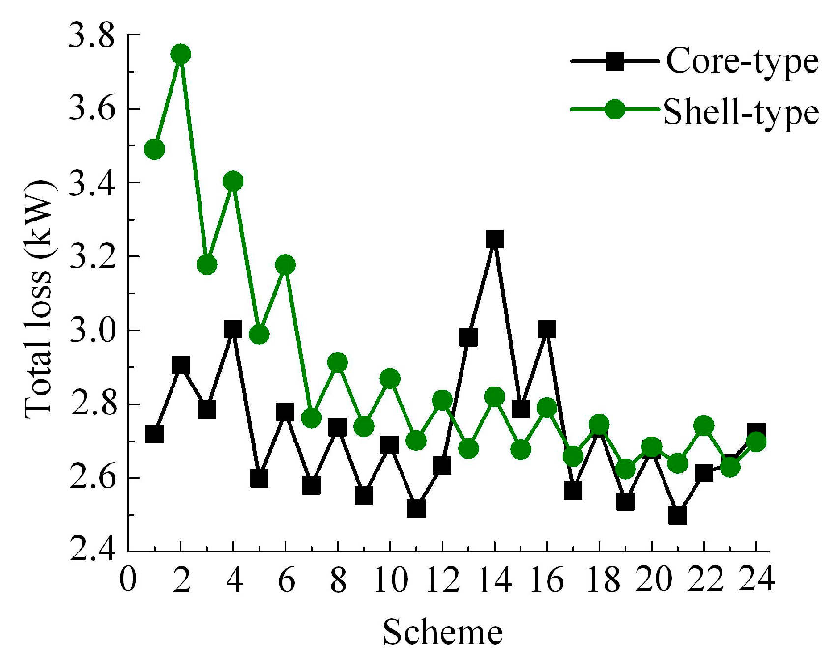
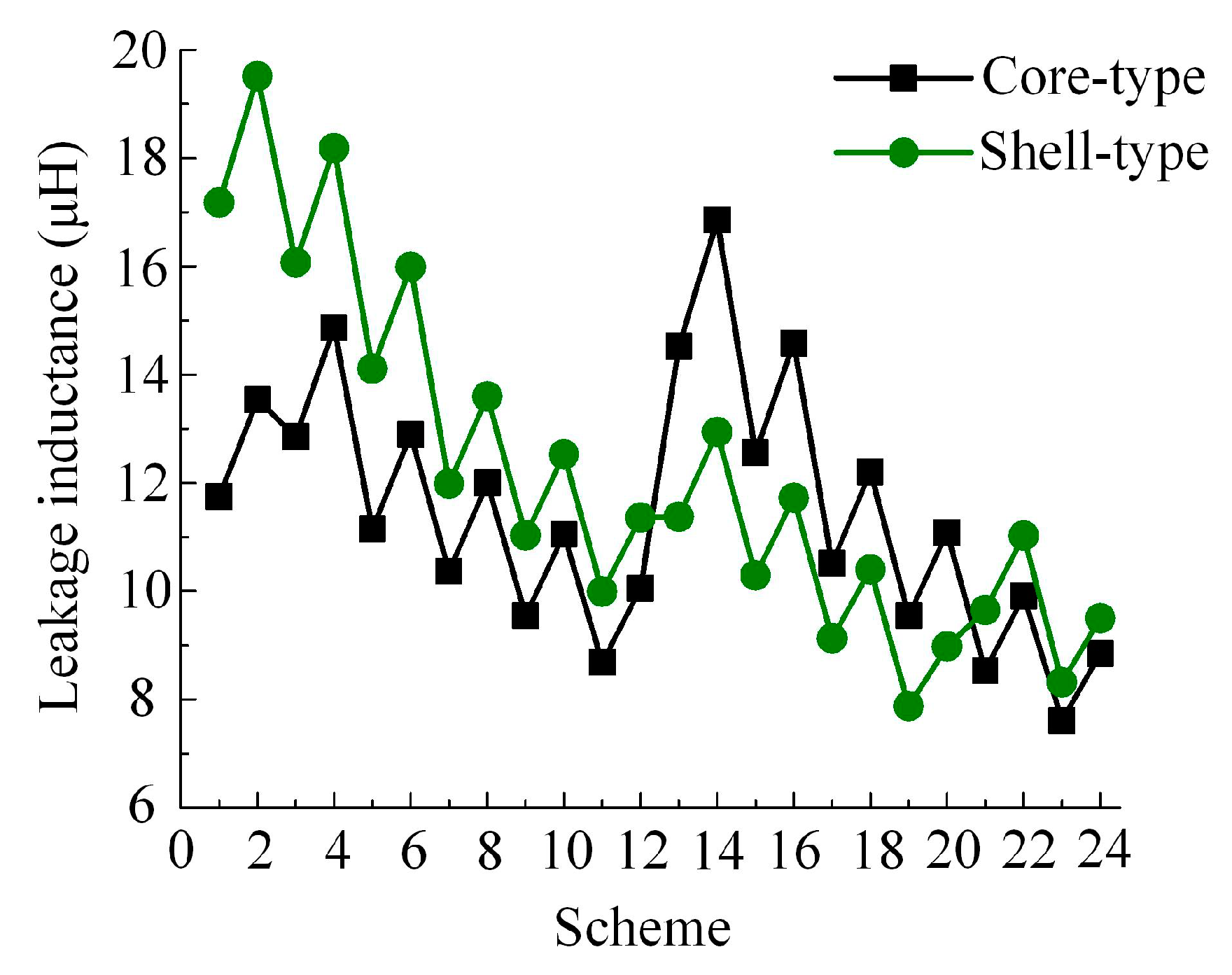
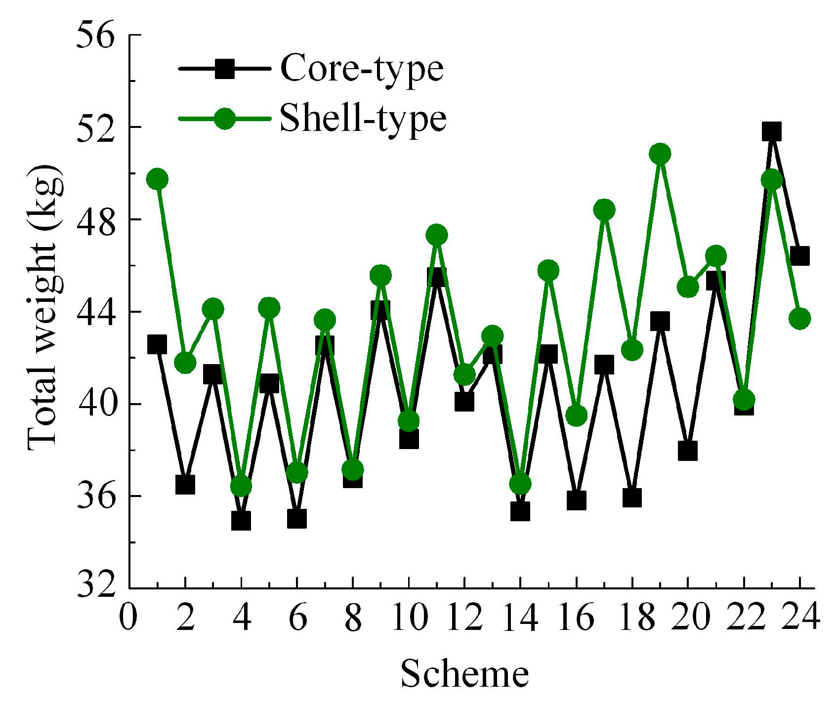
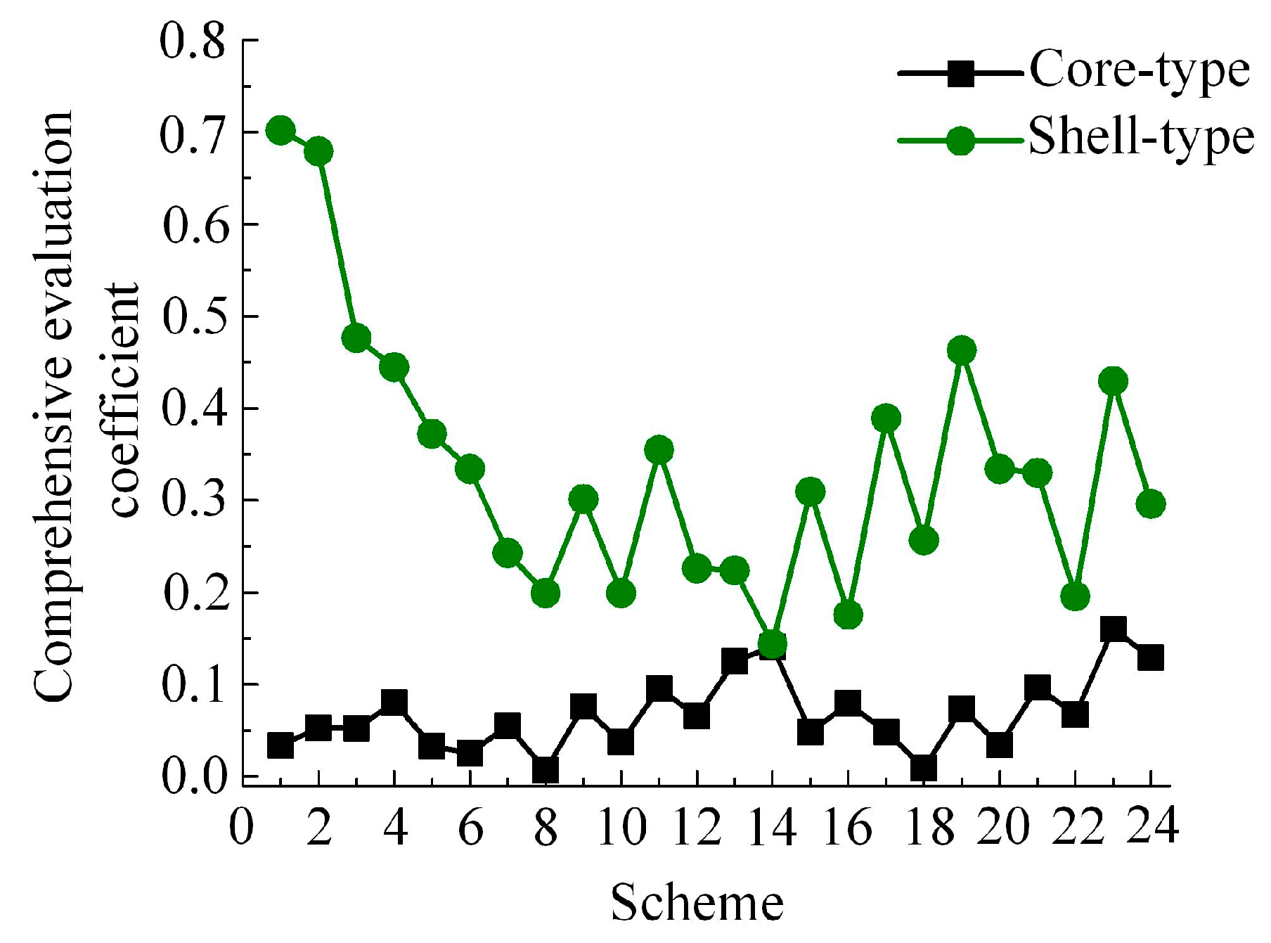
4. Design Results and Evaluation

By substituting the constant parameters and the 48 sets of variable parameters into the loss calculation equations, the winding loss, core loss, and the total loss of each scheme can be obtained. The total loss of core-type and shell-type schemes is shown in Figure 7.
According to the loss calculation results and the thermal models, the temperature rise of each part of the HPMFT can be checked, which shall not exceed ΔTmax. All 48 schemes passed the temperature rise verification.
On this basis, the leakage inductance and total weight of each scheme are calculated according to the equations derived above. The results are presented in Figure 8 and Figure 9, respectively. Through the establishment of the evaluation coefficient equation, the design schemes can be compared. For the target parameters such as total loss and weight of the HPMFT, the smaller the value is, the better the scheme is, and the equation of the evaluation coefficient, Eij, for them is shown as:
E ij = F ij min ( F i ) max ( F i ) min ( F i )
where Fij is the result of the scheme j of the target parameter Fi, min(Fi) and max(Fi) are respectively the minimum and maximum values of Fi in all schemes. In the 48 schemes, the minimum and maximum values of the total loss and weight are 2.50 kW, 3.75 kW, 34.92 kg, and 51.82 kg, respectively.
For the target parameter with expected value, such as the leakage inductance of the HPMFT, its evaluation coefficient is as below:
E ij = | F ij F 0 | max ( F i ) min ( F i )
where F0 is the expected value of the target parameter Fi. In this design case, the expected value of the leakage inductance is 12 μH. In all schemes, the minimum and maximum values of the leakage inductance are 7.62 and 19.51 μH, respectively.
In the design scheme j, the comprehensive evaluation coefficient considering the target parameters F1j, F2j, and F3j is presented in Equation (33).
E j = α 1 E 1 j + α 2 E 2 j + α 3 E 3 j
where α1, α2, and α3 are respectively the weight factor of the evaluation coefficients E1j, E2j, and E3j, satisfying α1 + α2 + α3 = 1. α1, α2, and α3 are evaluated according to the importance of target parameters F1, F2, and F3 for the design. The optimal scheme is the one that takes the minimum value of the comprehensive evaluation coefficient.
The weight factors of the evaluation coefficients of the total loss, leakage inductance, and total weight of the HPMFT are evaluated as α1 = α2 = α3 = 1/3, thus the comprehensive evaluation coefficients of the 48 design schemes are shown in Figure 10. It can be seen that the comprehensive evaluation coefficients of the core-type schemes are generally smaller than that of the shell-type schemes, which shows that the core-type is more suitable for the design of the HPMFT. Among the 24 design sets of the core-type scheme, the comprehensive evaluation coefficient of scheme 8 is 0.007, which is the minimum one. As a result, scheme 8 of the core-type scheme is the optimal choice which takes into account the total loss, leakage inductance, and total weight of the HPMFT.

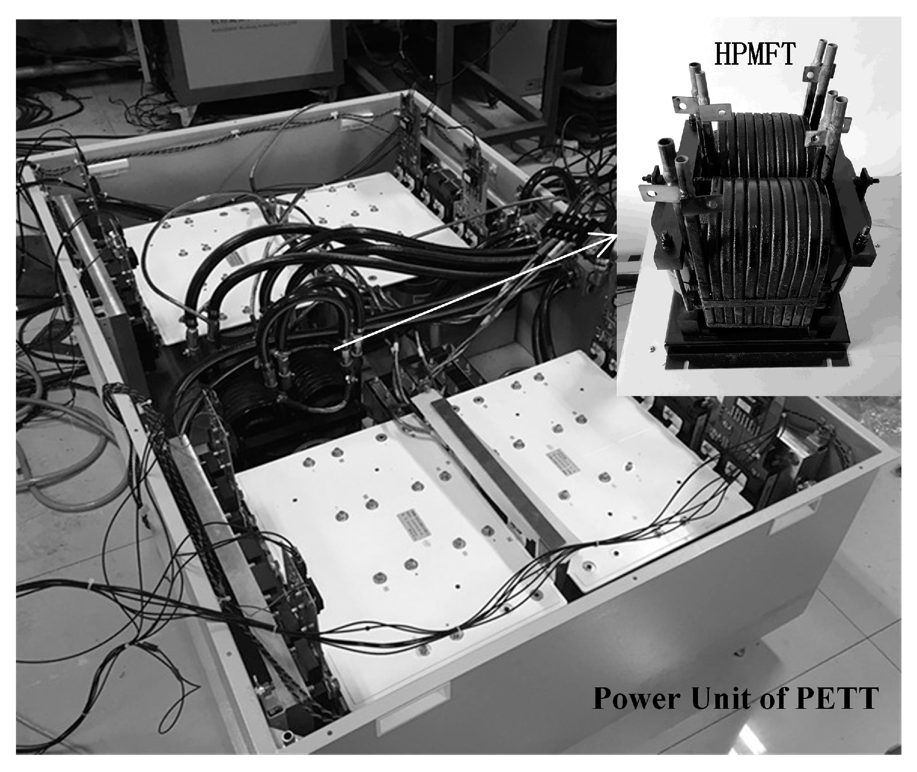
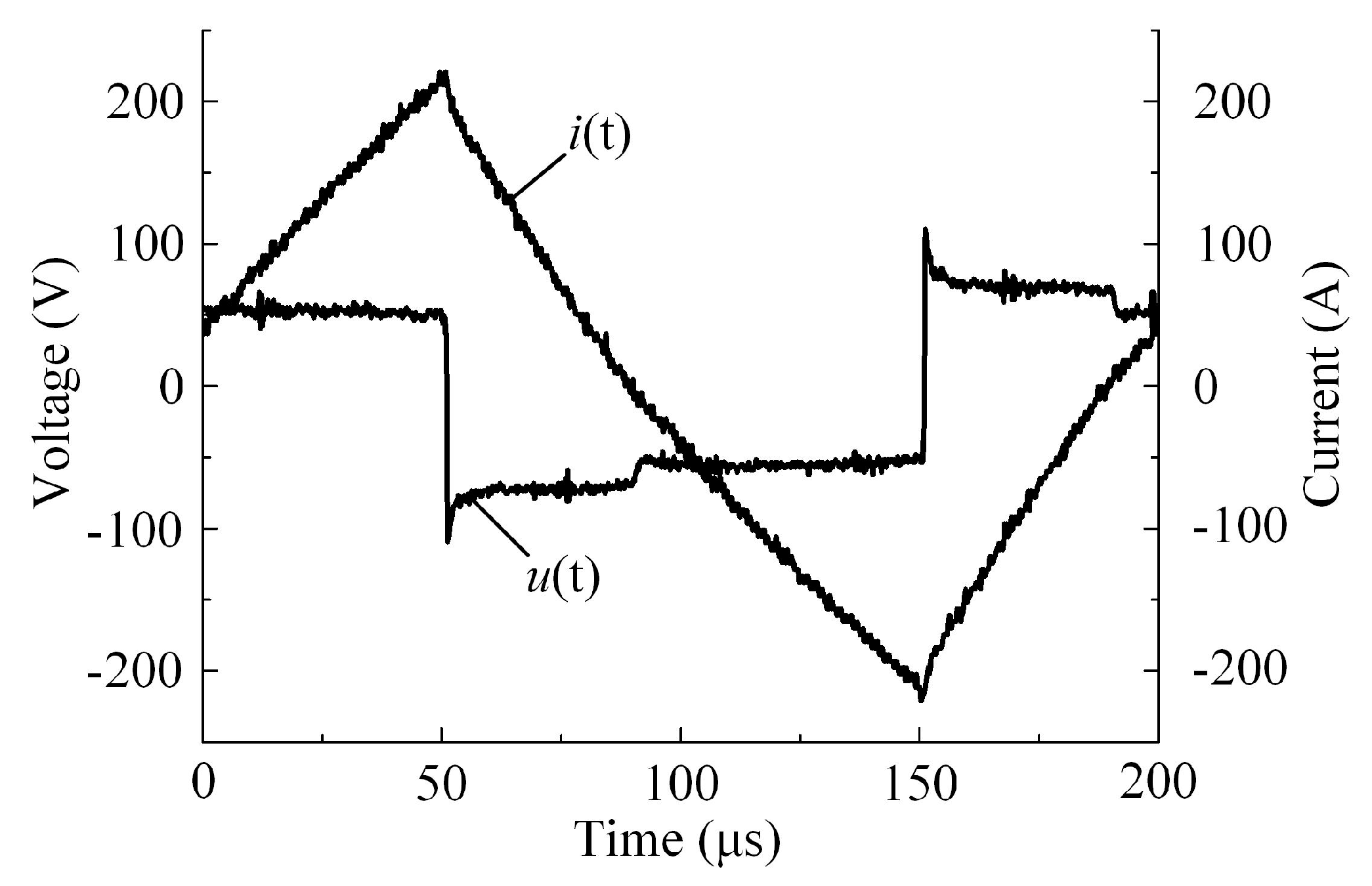
5. Experimental Validation

According to the optimal scheme, a prototype of the HPMFT is manufactured, and it is connected to a power unit of the PET for debugging, as shown in Figure 11. The short circuit and open circuit tests are carried out for the prototype.
A 5 kHz square-wave voltage is applied to the primary winding of the prototype when the secondary winding is short-circuited. The voltage and current waveforms of the primary winding in one period are presented in Figure 12. The amplitude and phase of the voltage and current at the fundamental frequency are obtained by Fourier series decomposition of the waveform data, then the short-circuit impedance of the prototype at the fundamental frequency is calculated. The sum of the AC resistance of the primary and secondary windings at 5 kHz is Rm0 = 40.17 mΩ, and the corresponding winding loss is PW0 = 1.98 kW. The inductance corresponding to the short-circuit reactance is Lσ0 = 12.89 μH. Compared to the design values of the optimal scheme PW = 1.82 kW, Lσ = 11.99 μH, the calculation errors of the winding loss and leakage inductance are 8.08% and 6.98%, respectively.
The reason for the errors is that the amplitude of square-wave voltage is low, and the voltage fluctuates. The analytical calculation equations of the high-frequency loss and leakage inductance are based on the Dowell model [25], which assumes that the winding occupies the whole core window, and the magnetic field intensity in the core window presents one-dimensional distribution. In practical applications, considering the end insulation distance, it is impossible for the winding to occupy the whole core window. Although the conductivity of the winding is corrected by the porosity coefficient, the errors of the equations based on the Dowell model still exist.
A 5 kHz/1.5 kV square-wave voltage is applied to the primary winding of the prototype when the secondary winding is open-circuited. The voltage and current waveforms of the primary winding in one period are presented in Figure 13, and the data of the waveforms are collected. Given the effective cross-sectional area, average magnetic circuit length of the core, and the primary winding turns of the transformer, the hysteresis loop of the core, whose area represents the core loss per unit volume in one magnetization period, can be obtained according to the waveform data. According to the density of the nanocrystalline core, the core loss is Pc0 = 0.82 kW when f = 5 kHz, and Bm = 0.7 T. According to the equation of WcSE, the design value of the core loss is Pc = 0.92 kW, with an error of 12.2%.
The reason for the error is that the core loss coefficients come from the parameters’ fitting of the experiment data of another transformer assembled by the same manufacturer’s cutting the nanocrystalline core. At present, the cutting process of the nanocrystalline core is not mature, so it is difficult to ensure the consistency of core incision, which leads to a certain difference in the air gap of the core during assembly. The air gap has a great influence on the core loss, resulting in the above error. According to the national standard of China GB1094.1, the error is less than 15%, which is still within the acceptable range.
The design weight of the prototype is Wt = 36.78 kg and the measured weight is Wt0 = 37.61 kg, thus the error is 2.21%. The reason for the error is that the weight of the transformer base and clamp are not considered in the design process.

6. Conclusions

This study conducted the optimal design of a 300 kW/5 kHz HPMFT, which is based on the lightweight demand of the PET used in the high-speed train. According to the system structure and parameters of the PET power unit, the design parameters of the HPMFT were determined. The design process of the HPMFT was established by adopting the core-type and shell-type structures, which also consider the sizes of nanocrystalline core and hollow conductor that can be customized. A prototype was manufactured and tested according to the optimal scheme, which was chosen according to the comprehensive evaluation standard. The errors between the designed and measured value of the loss, leakage inductance, and weight were acceptable, which verifies the correctness and effectiveness of the optimal design method.

Author Contributions

Conceptualization, Y.G., C.L., and X.Z.; methodology, Y.G. and X.Z.; software, C.L.; validation, Y.G. and X.Z.; formal analysis, Y.G.; investigation, C.L.; resources, C.L.; data curation, Y.G.; writing—original draft preparation, Y.G. and C.L.; writing—review and editing, Y.G., L.H., and X.Z.; visualization, C.L. and L.H.; supervision, X.Z.; project administration, X.Z.; funding acquisition, Y.G., C.L., L.H., and X.Z. All authors have read and agreed to the published version of the manuscript.

Funding

This research was funded by the National Natural Science Foundation of China, grant number 61673226; Nantong Basic Science Research Program, grant number JC2019125, JC2019127; Nantong University-Nantong Joint Research Center for Intelligent Information Technology, grant number KFKT2017A01, KFKT2017B06; Major Projects of Natural Science Research in Colleges and Universities of Jiangsu Province, grant number 19KJA350002; High-Level Talent Project of "Six Talent Peaks" in Jiangsu Province, grant number XNY-039.

Conflicts of Interest

The authors declare no conflict of interest.

Appendix A

Table A1. Values of the variable parameters in the core-type scheme.
SchemenpncC1
(mm)
dp
(mm)
ds
(mm)
SchemenpncC1
(mm)
dp
(mm)
ds
(mm)
SchemenpncC1
(mm)
dp
(mm)
ds
(mm)
1142601210910355121017104401210
21426010810103551081810440108
314340121011936012101994451210
414340108129360108209445108
5123451210131443012102184501210
6123451081414430108228450108
7113501210151243512102374601210
8113501081612435108247460108
Table A2. Values of the variable parameters in the shell-type scheme.
SchemenpncC1
(mm)
dp
(mm)
ds
(mm)
SchemenpncC1
(mm)
dp
(mm)
ds
(mm)
SchemenpncC1
(mm)
dp
(mm)
ds
(mm)
11416012109924512101773401210
214160108109245108187340108
314230121011825012101963451210
414230108128250108206345108
512235121013933012102174301210
612235108149330108227430108
710240121015833512102364351210
810240108168335108246435108

Appendix B

Table A3. Dimension equations of the core-type scheme.
SymbolEquationSymbolEquation
Dp1Di1 + 4(dp + di)dcdw + 2C1
Dp2Di1 + 4(dp + di)hchw + 2C1
Ds12(C1 + ncC2 + 2ds + 4dsc)tcncC2
Ds22(C1 + ncC2 + 2ds + 4dsc)Vc(dchcdwhw)tc
dw2(dp + ds + di + dsc) + dlDi1Ds1 + 4(ds + di)
hwnshs + (ns − 1) hts + 2hisDi2Ds1 + 4(ds + di)
Dp1Di1 + 4(dp+di)dcdw + 2C1
Dp2Di1 + 4(dp + di)hchw + 2C1
Table A4. Dimension equations of the shell-type scheme.
SymbolEquationSymbolEquation
Dp1Di1 + 4(dp + di)dcdw + 2C1
Dp2Dp1 + 8(dp + dl)hchw + 2C1
Ds12(2C1 + ncC2 + 2ds + 4dsc)tcncC2
Ds2Di2 + 4(ds + di)Vc2(dchcdwhw)tc
dw2(dp + ds + di + dsc) + dlDi1Ds1 + 4(ds + di)
hwnshs + (ns − 1)hts + 2hisDi2Dp2 + 4(dp + di)
Dp1Di1 + 4(dp + di)dcdw + 2C1
Dp2Dp1 + 8(dp + dl)hchw + 2C1

References

  1. Shamshuddin, M.A.; Rojas, F.; Cardenas, R.; Pereda, J.; Diaz, M.; Kennel, R. Solid State Transformers: Concepts, Classification, and Control. Energies 2020, 13, 2319. [Google Scholar] [CrossRef]
  2. Huber, J.E.; Kolar, J.W. Applicability of Solid-State Transformers in Today’s and Future Distribution Grids. IEEE Trans. Smart Grid 2017, 10, 317–326. [Google Scholar] [CrossRef]
  3. Duan, Q.; Ma, C.; Sha, G.; Zhao, C.; Li, Z. Research on flexible power distribution unit and its key technologies for energy internet. In Proceedings of the 2018 13th IEEE Conference on Industrial Electronics and Applications (ICIEA), Wuhan, China, 31 May–2 June 2018; pp. 2660–2665. [Google Scholar]
  4. Bahmani, M.A.; Thiringer, T.; Rabiei, A.; Abdulahovic, T. Comparative Study of a Multi-MW High-Power Density DC Transformer with an Optimized High-Frequency Magnetics in All-DC Offshore Wind Farm. IEEE Trans. Power Deliv. 2016, 31, 857–866. [Google Scholar] [CrossRef]
  5. Feng, J.; Chu, W.Q.; Zhang, Z.; Zhu, Z.Q. Power Electronic Transformer-Based Railway Traction Systems: Challenges and Opportunities. IEEE J. Emerg. Sel. Top. Power Electron. 2017, 5, 1237–1253. [Google Scholar] [CrossRef]
  6. Villar, I.; Mir, L.; Etxeberria-Otadui, I.; Colmenero, J.; Agirre, X.; Nieva, T. Optimal Design and Experimental Validation of a Medium-Frequency 400kVA Power Transformer for Railway Traction Applications. In Proceedings of the 2012 IEEE Energy Conversion Congress and Exposition (ECCE), Raleigh, NC, USA, 15–20 September 2012; pp. 684–690. [Google Scholar]
  7. Hannan, M.; Ker, P.J.; Lipu, M.S.H.; Choi, Z.H.; Rahman, M.S.A.; Muttaqi, K.M.; Blaabjerg, F. State of the Art of Solid-State Transformers: Advanced Topologies, Implementation Issues, Recent Progress and Improvements. IEEE Access 2020, 8, 19113–19132. [Google Scholar] [CrossRef]
  8. Lü, F.; Li, D.; Guo, Y.; Fu, C.; Wang, H. Optimal design of compact main insulation structure of PETT. In Proceedings of the 2015 18th International Conference on Electrical Machines and Systems (ICEMS), Pattaya, Thailand, 25–28 October 2015; pp. 303–306. [Google Scholar]
  9. Yue, Q.; Li, C.; Cao, Y.; He, Y.; Cai, B.; Wu, Q.; Zhou, B. Comprehensive Power Losses Model for Electronic Power Transformer. IEEE Access 2018, 6, 14926–14934. [Google Scholar] [CrossRef]
  10. Liu, Z.; Zhu, J.; Zhu, L. Accurate Calculation of Eddy Current Loss in Litz-Wired High-Frequency Transformer Windings. IEEE Trans. Magn. 2018, 54, 1–5. [Google Scholar] [CrossRef]
  11. Chen, B.; Li, L. Semi-Empirical Model for Precise Analysis of Copper Losses in High-Frequency Transformers. IEEE Access 2018, 6, 3655–3667. [Google Scholar] [CrossRef]
  12. Chen, X.; Wang, J.; Griffo, A.; Spagnolo, A. Thermal Modeling of Hollow Conductors for Direct Cooling of Electrical Machines. IEEE Trans. Ind. Electron. 2020, 67, 895–905. [Google Scholar] [CrossRef]
  13. Liu, X.; Wang, Y.; Islam, R.; Lei, G.; Liu, C.; Zhu, J. Comparison of electromagnetic performances of amorphous and nanocrystalline core-based high frequency transformers. In Proceedings of the 2014 17th International Conference on Electrical Machines and Systems (ICEMS); Institute of Electrical and Electronics Engineers (IEEE), Hangzhou, China, 22–25 October 2014; pp. 2028–2032. [Google Scholar]
  14. Villar, I.; Viscarret, U.; Etxeberria-Otadui, I.; Rufer, A. Global Loss Evaluation Methods for Nonsinusoidally Fed Medium-Frequency Power Transformers. IEEE Trans. Ind. Electron. 2009, 56, 4132–4140. [Google Scholar] [CrossRef]
  15. Shen, W.; Wang, F.; Boroyevich, D.; Tipton, C. Loss Characterization and Calculation of Nanocrystalline Cores for High-Frequency Magnetics Applications. IEEE Trans. Power Electron. 2008, 23, 475–484. [Google Scholar] [CrossRef]
  16. Garcia-Bediaga, A.; Villar, I.; Rujas, A.; Mir, L.; Rufer, A. Multiobjective Optimization of Medium-Frequency Transformers for Isolated Soft-Switching Converters using a Genetic Algorithm. IEEE Trans. Power Electron. 2016, 32, 1. [Google Scholar] [CrossRef]
  17. Li, Y.; Sun, Q.; Qin, D.; Cheng, K.; Li, Z. Power Control of a Modular Three-Port Solid-State Transformer With Three-Phase Unbalance Regulation Capabilities. IEEE Access 2020, 8, 72859–72869. [Google Scholar] [CrossRef]
  18. Huang, P.; Mao, C.; Wang, D.; Wang, L.; Duan, Y.; Qiu, J.; Xu, G.; Cai, H. Optimal Design and Implementation of High-Voltage High-Power Silicon Steel Core Medium-Frequency Transformer. IEEE Trans. Ind. Electron. 2017, 64, 4391–4401. [Google Scholar] [CrossRef]
  19. Zhang, L.; Zhang, D.; Shui, H.; Yuan, Y.; Pei, Q.; Zhu, J. Optimisation design of medium frequency transformer for the offshore dc grid based on multi-objective genetic algorithm. IET Power Electron. 2017, 10, 2157–2162. [Google Scholar] [CrossRef]
  20. Drofenik, U. A 150kW Medium Frequency Transformer Optimized for Maximum Power Density. In Proceedings of the 2012 7th International Conference on Integrated Power Electronics Systems (CIPS), Nuremberg, Germany, 6–8 March 2012; pp. 1–6. [Google Scholar]
  21. Du, Y.; Baek, S.; Bhattacharya, S.; Huang, A.Q. High-voltage high-frequency transformer design for a 7.2kV to 120V/240V 20kVA solid state transformer. In Proceedings of the IECON 2010—36th Annual Conference on IEEE Industrial Electronics Society, Glendale, AZ, USA, 7–10 November 2010; pp. 493–498. [Google Scholar]
  22. Du, S.B.Y.; Wang, G.; Bhattacharya, S. Design considerations of high voltage and high frequency transformer for solid state transformer application. In Proceedings of the IECON 2010—36th Annual Conference on IEEE Industrial Electronics Society, Glendale, AZ, USA, 7–10 November 2010; pp. 421–426. [Google Scholar]
  23. Lü, F.; Guo, Y.; Wang, Y.; Yu, D.; Li, P. AC resistance calculation method for hollow conductor windings in high power medium frequency transformers. Proc. CSEE 2016, 23, 6552–6559. [Google Scholar]
  24. Steinmetz, C. On the law of hysteresis. Proc. IEEE 1984, 72, 196–221. [Google Scholar] [CrossRef]
  25. Dowell, P. Effects of eddy currents in transformer windings. Proc. Inst. Electr. Eng. 1966, 8, 1387–1394. [Google Scholar] [CrossRef]
Figure 1. System structure of the power electronic transformer (PET).
Energies 13 03654 g001
Figure 2. Design process of the HPMFT.
Energies 13 03654 g002
Figure 3. Structure design of the core-type HPMFT: (a) front view; (b) structure of the winding; (c) side view; (d) top view.
Energies 13 03654 g003
Figure 4. Structure design of the shell-type HPMFT: (a) front view; (b) structure of the winding; (c) side view; (d) top view.
Energies 13 03654 g004
Figure 5. Steady-state thermal model of the core-type HPMFT.
Energies 13 03654 g005
Figure 6. Steady-state thermal model of the shell-type HPMFT.
Energies 13 03654 g006
Figure 7. Total loss of the design schemes.
Energies 13 03654 g007
Figure 8. Leakage inductance of the design schemes.
Energies 13 03654 g008
Figure 9. Total weight of the design schemes.
Energies 13 03654 g009
Figure 10. Comprehensive evaluation coefficients of the design schemes.
Energies 13 03654 g010
Figure 11. Prototypes of the power unit of PET and HPMFT.
Energies 13 03654 g011
Figure 12. Voltage and current waveforms of the short circuit test.
Energies 13 03654 g012
Figure 13. Voltage and current waveforms of the open circuit test.
Energies 13 03654 g013
Table 1. Design parameters of the high-power medium-frequency transformer (HPMFT).
DescriptionSymbolValue
rated outputPn300 kW
frequencyf5 kHz
voltage amplitude of primary windingUpm1.5 kV
insulation voltage of primary windingUip27.5 kV
insulation voltage of secondary windingUis1.7 kV
turn ratiok1:1
maximum temperature riseΔTmax70 °C
expected leakage inductanceL012 μH
Table 2. Equations of leakage inductance.
RegionSymbolEquation
first layer of the primary windingLp1 μ δ cu D p 1 F rp / 2 h
first layer of the secondary windingLs1 μ δ cu D s 1 F rs / 2 h
insulation area between the first layer of the windingLi1 μ d i D i 1 / h
second layer of the primary windingLp2 μ δ cu D p 2 F rp / 2 h
second layer of the secondary windingLs2 μ δ cu D s 2 F rs / 2 h
insulation area between the second layer of the windingLi2 μ d i D i 2 / h
first layer of the primary windingLp1 μ δ cu D p 1 F rp / 2 h
first layer of the secondary windingLs1 μ δ cu D s 1 F rs / 2 h

