Article

New Design of Copper–Inconel 601 Ground Electrode Spark Plug Based on a Thermo-Mechanical Model

1
LTDS, UMR 5513 CNRS, Ecole Nationale d’Ingénieurs de Saint-Etienne, Université de Lyon, 42023 Saint-Etienne, France
2
Federal Mogul Powertrain Ignition Products SAS, 42140 Chazelles sur Lyon, France
3
LGF, UMR 5307 CNRS, Mines Saint-Etienne, Université de Lyon, 42023 Saint-Etienne, France
4
LTDS, UMR 5513 CNRS, Ecole Centrale de Lyon, Université de Lyon, 69134 Ecully, Lyon, France
*
Author to whom correspondence should be addressed.
Submission received: 25 June 2020 / Revised: 13 July 2020 / Accepted: 22 July 2020 / Published: 24 July 2020
(This article belongs to the Special Issue Advances in Spark-Ignition Engines)

Abstract

:
Inconel 601 is one material of choice for intermediate- to high-temperature protective coatings for spark plugs’ ground electrodes. Production of ground electrodes of spark plugs implies the following operations: the tamping of the copper core in an Inconel 601 cup, cold-forming of the assembly, annealing, welding, and bending of the final spark plug. On the production line, the use of Inconel 601 as a protective coating for ground electrodes leads to possible cracking in the welded area after bending. In the present paper, possible causes of cracking are analyzed. It is clearly shown that a combination of Copper –Inconel interface oxidation, Inconel yielding during the heat treatment, and micro-movements during bending lead to cracks in the welded area of the ground electrode. First, the detrimental effect of gaps, between Copper and Inconel 601, is shown experimentally. Second, a thermo-mechanical analysis combined with SEM (Scanning Electron Microscopy) observations identified the annealing treatment and interface oxidation as the main cause of gaps. Third, bending simulations show the relation between these gaps and cracking. Finally, a new ground electrode design, preventing cracks, is suggested.

1. Introduction

Considering the increased cost of oil and the stringent emission regulations, engine design should satisfy three important expectations: lower fuel consumption, lower emission, and correct function of engine. The combustion of air/fuel mixture is the main task of spark plugs in spark ignition engines. Spark plugs produce about a thousand sparks per minute in a combustion chamber under high pressures and temperatures [1]. Engine modifications to decrease emission and lower fuel consumption cause intensified thermal loads on the spark plugs [2]. To resist high-temperature wear and corrosion, ground electrodes of spark plugs formed by a copper core and a high-temperature corrosion-resistant Nickel-based alloy mantle have been developed. Inconel 601 is the material of choice for high-temperature corrosive environments [3,4].
Coating with Inconel 601 will be done by lubricated cold working (Figure 1a,b). Then, the ground electrodes are submitted to an annealing (in a very large furnace) at a temperature of 1040 °C during 20 min in a protected atmosphere containing hydrogen and nitrogen (Figure 1c). Cooling is performed using liquid nitrogen. Finally, the assembly is assembled to a steel shell by resistance braze welding (Figure 1d), and bent (Figure 1e,f). Bending is done in a specially designed tool. Several operations are used to guarantee perfect alignment of the tool and the ground electrode. Resistance braze welding is commonly used for assembling different kind of materials (copper, nickel-based alloy, and steel). The effect of different welding parameters was analyzed in detail in Reference [5].
The use of Inconel 601 led to some unanticipated difficulties during the different production phases. After bending, a small proportion (ppm) of spark plugs revealed unexpected cracking in the welded volume. The first investigations of spark plugs with cracks systematically revealed a gap between the copper core and the Inconel 601 mantle (Figure 2). Experimental evidence thus pointed to a strong correlation between cracking in the welded zone and the presence of gaps. High-temperature corrosion of Inconel 601 has been analyzed extensively in the literature [3,4]. However, the present paper analyzes the synergetic effects between Cu–Inconel 601 interface pollution, heat treatment-induced Inconel yielding, and cracking due to micro-movement during bending. Only the combination of experimental characterizations with thermo-mechanical analysis of the heat treatment and the bending procedure allow to understand these synergetic effects. To the best of our knowledge, this is completely novel and leads to an innovative ground electrode design.
Section 2 is devoted to the experimental analysis. First, samples were prepared under laboratory conditions, permitted to generate two series of ground electrodes with and without gaps, respectively. A systematic analysis confirmed that gaps cause cracking during bending. At this point, the detrimental effect of gaps is thus confirmed. However, the possible cause of gaps is still to be elucidated. Therefore, Section 2 ends with a microscopic characterization of samples exhibiting gaps. These analyses clearly reveal an oxide layer at the copper–Inconel interface. Thus, bad interface adhesion may be suspected as the main cause of gaps. This led to the thermo-mechanical analysis of the annealing treatment offered in Section 3. This model confirms the tendency of gap formation during heat treatment for small adhesion between the copper core and Inconel mantle. The welding was analyzed in detail in Reference [5]. Gaps induced by the heat treatment will not disappear during welding. Section 2 and Section 3 confirm the causes of gap formation: bad adhesion and yielding of the Inconel mantle during the heat treatment. However, at this stage, the detrimental effect of possible gaps during the bending operation still has to be clarified. Possible micro-movements during bending were suspected to cause cracking. The bending model in Section 4 compares the stress distribution in electrodes with and without gaps. Effectively, gaps lead to stress concentrations in the welded volume prone to cracking. At the end of Section 4, all the possible causes of cracks induced by residual gaps are clearly understood. Clearly, gaps have to be avoided at any cost. As mentioned above, only a few parts per million of ground electrodes exhibit heat treatment-induced gaps and consequent cracking during bending. The microscopic observations of Section 2 suggest bad adhesion due to oil pollution at the interface. This pollution corresponds to oil residues after the cold forming of the Inconel mantle. Consequently, two solutions may be considered. The first solution consists of very costly cleaning and control procedures to guarantee oil-free interfaces and consequently, good adhesion between the copper core and Inconel mantle. Based on the mechanical analysis of the heat treatment, we opted for a less expensive solution. Section 5 presents a new ground electrode design preventing large plastic deformations of the Inconel mantle and, hence, avoiding the gap formation.

2. Experimental

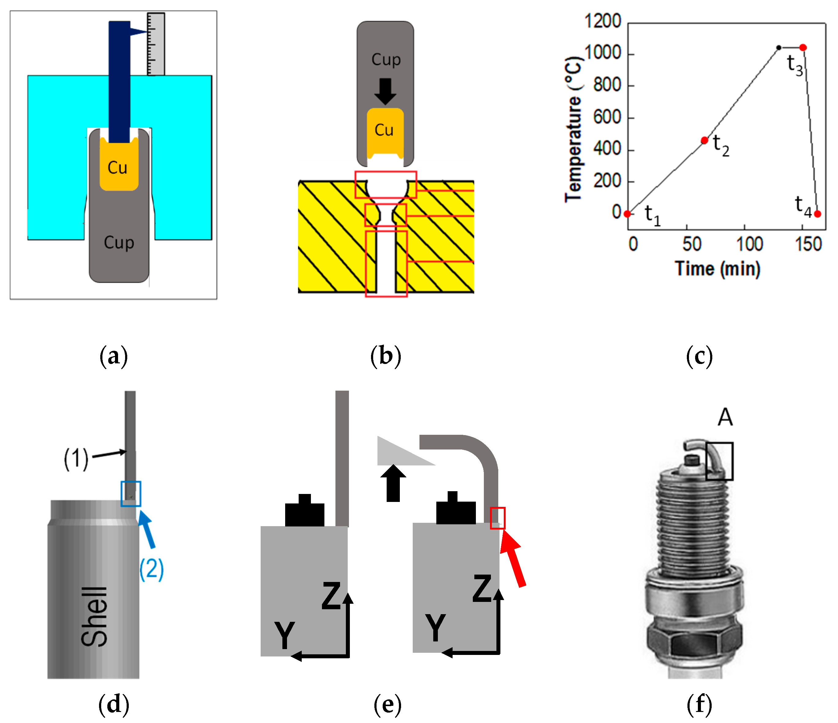
2.1. Materials and Process

Two materials were used in this study: Cu-OF (Free-Oxygen Copper)high-purity copper wires and Inconel 601 [6,7,8,9] coatings. The chemical compositions are given in Table 1. Oil residues after cold forming were suspected to cause bad adhesion, and consequently, gaps after the heat treatment. Hence, samples were produced under laboratory conditions. To ensure cleanliness, the Inconel buckets were thoroughly washed, and cleaned in an ultrasonic bath (96° ethyl alcohol). Then, 18 specimens without oil and 18 specimens with intentionally added oil were prepared. For all samples, the copper wires were tamped in the Inconel 601 mantle. Then, the assembly was cold-formed under the presence of CONDAMAX ALS oil (commercial brand). Finally, all samples were annealed at 1040 °C during 20 min in a hydrogen- and nitrogen-protected atmosphere. Cooling was achieved in liquid nitrogen.

2.2. Interface Gaps after Heat Treatment

Gaps between the copper core and Inconel 601 were determined after heat treatment by tomographic observations on a North Star Imaging® topographer (with two-dimensional (2D)/three-dimensional (3D) radiology, a voltage range of 10 to 160 kV) under a magnification of 2000 on 36 samples at different locations on each sample. Figure 3 shows a typical cross-section obtained by tomography with indication of the measurement zones. In the following, Zi designates the value (in µm) of the considered gap. The corresponding measurement locations (in mm) are given in Figure 3b. On each sample, the lateral gaps were measured in the center (Z3). Gaps, Z1, between the upper end of the copper core and the Inconel bucket were also recorded. Thus, for each series of samples (with or without oil), there were 18 tomographic measurements for Z1 and 36 for Z3. The gaps at locations Z1 to Z4 were checked by optical light microscopy on ten samples. The correlation between tomographic and optical observations was satisfactory. The largest difference between the two measurement techniques was smaller than 4%.
Table 2 summarizes the gaps at Z1 and Z3, determined by tomography on 18 oiled and 18 non-oiled samples. At Z3, two measurements (each side) were made on each electrode. Only the maximum value of both was recorded. Both gaps Z1 and Z3 are much larger on oiled samples than on the non-oiled ones. For both series, the standard deviation is very large. Let us consider an interval of 1 standard deviation on each side of the mean value. Gap Z1 leads to overlapping intervals for both series (oiled and non-oiled). However, these intervals do not intersect for gap Z3. In the following section, the relation between the measured gaps and the tendency to crack during bending is analyzed.

2.3. Cracking during Bending

All electrodes of both series were welded and bent. During the welding operation, the maximum gap, Z3, was on the outer side of the electrode (red rectangle in Figure 4). After welding and bending, all electrodes were observed, once more, by tomography to detect eventual cracks. Figure 4 summarizes the observations on the 18 oiled and 18 non-oiled electrodes. In the (Z1, Z3)-space, clearly, two domains appear. For Z3 smaller than 10 µm, no cracks were detected. All electrodes with gaps (after heat treatment) larger than 12 µm exhibited cracks after bending. Determining the exact boundary shared by both domains would need a larger number of tests, however, this is not the purpose of the present work.
All “oiled” electrodes exhibited cracks after bending, while all “non-oiled” electrodes underwent bending without leading to cracks. Thus, large gaps (Z3 > 14 µm) systematically led to cracking. Cleaning the samples with the lab procedure leads to heat treatment-induced gaps smaller than this threshold (samples represented in blue in Figure 4). This corresponds to the main results on the production line. However, all oiled samples exhibited large gaps and cracks after bending. These samples represent a small percentage on the production line. To show the detrimental effect of oil “residues”, the detrimental effect of intentional added oil on otherwise clean samples has been proven. The copper–Inconel interface of “oiled” samples has been characterized thoroughly. Section 2.4 presents the main results of these characterizations needed for the mechanical analyses.

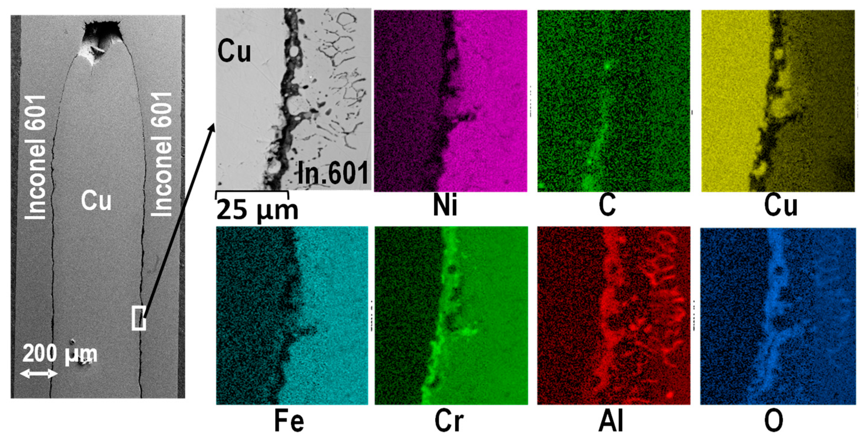
2.4. Characterization of the Inconel–Cu Interface

Oxidation of Inconel 601 was thoroughly analyzed in the scientific literature [8,9]. Even at temperatures above 1000 °C, a protective Cr2O3 layer exists (see References [1,2,10,11,12,13]), and the oxidation rate seems to be controlled by transport through this layer [1,8].
In the present work, the oxidation kinetics is not addressed. The focus is on the formation of oxides at the Inconel–Cu interface. First, the chemical compositions of the different components, present at the Inconel–Cu interface after annealing of “oiled” samples, were determined by Raman Microscopy (XPloRA ONE Raman, laser with a wavelength of 532 nm, and a range between 150 and 4000). The spectra exhibit typical peaks [14] for NiO, Cr2O3, and Al2O3 at the Inconel–Cu interface.
The presence of oxides in oiled samples was confirmed by EDX (energy dispersion X ray)analyses (SEM (Scanning Electron Microscopy): ZEISS SUPRA 55 at 20 keV and WD (Working distance) = 10 mm, 10−3 Pa with EDX detector: Oxford XMAX 80 mm2). Figure 5 offers detailed EDS maps of the Cu–Inconel interface. All the maps were done in the white rectangle (continuous line on the SEM observation). Close to the interface with Cu, the Inconel 601 presents increased Cr and O contents corresponding to Cr2O formation, whereas the Inconel core is Cr-depleted and enriched in aluminum and oxygen. At a distance larger than 10 µm inside the Inconel 601, Al was detected in grain boundaries. The latter suggests Al2O3 formation in the Inconel grain boundaries. Thus, EDS (energy dispersion spectrometry) maps indicate the formation of a Cr2O3 layer at the Inconel surface and the formation of an underlying (inside the Inconel) layer with high Al2O3 content, preferentially at the Inconel grain boundaries. Several authors [15,16,17] have mentioned oxide formation at Inconel grain boundaries (Cr2O3 and Al2O3).
Both oxides (Al2O3 and Cr2O3) are formed at high temperature (during the heat treatment). Both oxides exhibit much smaller coefficients of thermal expansion than the Inconel matrix. During cooling, the Cr2O3 layer will be submitted to compressive stresses. However, the Al2O3, present at the grain boundaries, will undergo large tensile stresses. This may lead to localized grain boundary cracks. Figure 6a–g depicts optical observations of the Inconel 601–copper interface prior to welding and bending. These observations show the damaged interface after heat treatment. Figure 6h shows cracks after welding and bending. Figure 6a–e corresponds to the upper half of one sample and Figure 6h corresponds to the lower half of another sample. The optical observations essentially highlight a damaged interface. Figure 6f shows a SEM observation in zone B. On this SEM observation, grain boundary damage in the Inconel 601 is visible. The same zone (same sample) was used for the EDS mappings in Figure 5. Moreover, crack propagation starting from this interface (during bending) is shown in Figure 6h. Prior to welding and bending, the microstructure of region C corresponds to Figure 6f. However, the micro-cracks are smaller. Crack formation in region C (Figure 6h), during bending, is controlled by the presence of micro-cracks and the particular boundary conditions during the bending operation. This is addressed in Section 4.
Thus, all the results point to oxide formation at the Inconel grain boundaries. A similar mechanism was reported by Garat et al [17]. These oxides grow at high temperature during the annealing treatment. They initiate grain boundary damage in the Inconel 601 during cooling to room temperature. Hence, in the following section, the annealing treatment is modeled assuming zero adherence between Copper and Inconel 601.

3. Thermo-Mechanical Analysis of Current Ground Electrode Design

The thermal strains and stresses induced by the annealing and cooling were modelled using Sysweld™ [18]. The effect of plastic dissipation on heat transfer is neglected. Therefore, the simulation is based on a thermal followed by a mechanical analysis [19,20,21,22,23]. The metallurgical phenomena are not taken into account. The heat transfer analysis is based on the solution of the classical heat equation [23]. The mechanical analysis is based on the usual equations describing the static equilibrium and additive small strain decomposition   ε = ε e + ε p + ε t h , where   ε ,   ε e ,   ε p , and ε t h are the total, elastic, plastic, and thermal strains, respectively. All temperature-dependent material properties are given in Table 3 and Table 4. The coefficients of thermal expansion of the two materials were determined by dilatometry tests.
Different geometries will be studied depending on the presence or absence of initial gaps (prior to annealing) between copper and Inconel 601. Two-dimensional (2D) generalized plane strain models will be used. The generalized plane strain assumption in Sysweld™ [18], allows 2D models with non-zero (but constant) strain   σ z z . The latter adds a degree of freedom to the problem. It is well-known that such thermo-mechanical models overestimate the σ z z stresses due to the constraint imposed by the generalized plane strain condition. In order to check the ability of such models to predict gap formation in the (xy) plane, a comparison with a full 3D model will be done in one case (without initial gap). First-order finite elements with selectively reduced integration will be used both in 2D and 3D [18], due to their ability to simulate complex elastoplastic problems.

3.1. Geometry and Finite Element Mesh

Symmetry allows modelling ½ of the electrode in 2D, and ¼ in 3D. Figure 7a depicts the dimensions of the ground electrode. X designates an axis of symmetry. Two contact geometries were simulated: without initial gap (Figure 7b) and with an initial gap of 5 µm (Figure 7c).
Several mesh densities were tested. Figure 8 depicts the optimum mesh finally used in all further analyses. With 10 elements in the y direction, corresponding to an element size of 0.06 mm, mesh refinement would not lead to significantly different results.
On interfaces between solid bodies, Sysweld™ uses a master-slave algorithm. Mechanical contact is defined between interacting faces using an algorithm which strictly enforces a non-penetration condition. Perfectly sliding conditions are assumed at the interface.

3.2. Thermo-Mechanical Loading

The ground electrode was placed in a furnace with homogeneous temperature. The annealing temperature as a function of time is depicted in Figure 1c. There was an initial increase from room temperature to 1040 °C during 20 min, followed by a plateau, then rapid liquid nitrogen cooling, and finally, slow air cooling to room temperature. As the heating is long, a homogeneous temperature was applied to all the nodes of the ground electrode. During cooling, a heat exchange coefficient between the external surface of the Inconel 601 and the nitrogen atmosphere, hnitrogen (3000 W K/m2), was considered (Figure 7). The external temperature was set to −150 °C. The heat exchange coefficient between air existing in the gap and both Inconel 601 and copper was set to hgap (Figure 7). For thermal contact, a geometric search was performed to find the element on the master surface onto which each element on the slave surface is subjected. The equivalent gap conductibility was defined as the inverse of the gap width (g) multiplied by the thermal conductivity of the air ( k g ) in the gap:
h g a p = k g / g
Displacement components are blocked so as to respect symmetry conditions for the 2D and the 3D models. At point A, the copper is linked to Inconel so that its body motion will be blocked (Figure 7). A sliding contact between copper and Inconel 601 (Figure 7) was assumed. Time steps of 10 s and 1 s were used for the heating and the cooling, respectively. For the mechanical calculations, a time step of 0.5 s was used.

3.3. Stress Distribution in the Electrode during Annealing

Figure 9 depicts the distribution of axial stress, σxx, at different times during the annealing treatment (Figure 1c). The results correspond to an initial gap (prior to annealing) of 5 µm. The 3D and 2D generalized plane strain models predict very close axial stress distributions in the Inconel. After cooling to room temperature, a difference in the copper core is observed. The sole difference between 2D and 3D models concerns the compressive stresses ( σ z z ) predicted in the copper core, which are higher with the generalized plane strain model. As damage is observed in the Inconel 601, we focus essentially on the stress field in this material. Concerning the Inconel 601 coating, only both ends of the electrode are submitted to significant stresses at high temperature (t2 and t3). At room temperature (t4), no noteworthy stress subsists in the Inconel. At high temperature, the stress in the Inconel 601 varies continuously from less than −80 MPa to more than +80 MPa through the thickness at both ends of the electrode. This stress distribution corresponds to bending of the Inconel 601 coating. The same stress levels are achieved without an initial gap of 5 µm.
Figure 10b depicts the axial stress, σxx, at time t2 (beginning of temperature plateau) in the Inconel coating. At the very top of the electrode (x = 0), the stress is close to zero. This corresponds to the Inconel 601 closing of the electrode. For x > 0, the outer Inconel 601 (lines L3, L4) is submitted to compressive stresses, whereas the inner Inconel 601 (lines L1, L2) is submitted to positive axial stresses. The coating is submitted to bending around the z-axis.
During heating, copper expansion induces compressive loading along the copper–Inconel interface. At the electrode top (upper part in Figure 10a), thermal expansion of copper is hindered most. At the “free” bottom, thermal expansion is hindered less. Effectively, the induced bending stresses (σxx) decrease close to the free end. This point will be of prime significance to suggest a new electrode design.
The consequence of residual plastic deformation in the Inconel (the gaps at room temperature) is discussed thoroughly in the Section 3.4.

3.4. Gaps versus Time

Predictions of the 2D plane strain model were checked in the preceding section on the stress maps. Gaps after annealing and cooling have been simulated with this model for both assumptions: an initial gap prior to heat treatment of 5 µm and no initial gap.
Figure 11 shows the gaps as a function of time predicted by the 2D model with an initial gap of 5 µm and without an initial gap. For the gap at Z1 (Figure 11a), a small time delay as well as a difference in the maximum value are observed. In both cases, with or without initial gap, no contact at the top of the ground electrode is observed. Gaps Z2 to Z4 (along the electrode axis) are only slightly affected by an initial gap of 5 µm (Figure 11b). The final gap in the middle of the electrode (Z3) depends on the presence or absence of an initial gap. If no initial gap is present, contact loads between Copper and Inconel 601 all along the x axis prevent the free bending movement. This leads to smaller gaps at Z3 than in the case without an initial gap.
Positive gaps are predicted during the heating. Copper exhibits a larger coefficient of thermal expansion than Inconel 601. Hence, at first glance, a decrease of the gaps would be expected during heating. But, closing the bottom of the electrode prevents the latter from “free” expansion. Hence, locally, at the very bottom of the electrode, the Inconel 601 is submitted to severe contact loads and bending.
As the presence of gaps seems to play a key role, the model results were checked at the 4 locations defined in Figure 3 by light optical measurements on 10 samples. To the best of our knowledge, no such measurements have been made on comparable geometries previously. Ishikawa [24] analyzed thermal stresses in a plane cylinder. Bengeri et al [25] modeled shrink fit stresses in circular cylinders. However, thermal stresses were not analyzed in hollow cylinders with a rectangular cross-section. Thus, the only verification available consists in comparing new simulation and new experimental measurements. Table 5 shows simulation results corresponding to a zero initial gap and the experimental data. Considering the complexity of the phenomena involved, a good agreement between experimental observations and mechanical predictions of gaps after annealing is achieved. The presence of gaps after annealing is confirmed. Persistence of the gaps after cooling clearly confirms irreversible (plastic) deformation of the Inconel 601.
At this stage, the presence effect of gaps after annealing treatment has been observed experimentally. The existence was attributed to small (no) adhesion between the Copper core and Inconel. This assumption was justified by present thermomechanical analysis. The detrimental effect of the gaps during annealing has been observed experimentally. In the next section, the effect of gaps on the bending behavior is analyzed by a mechanical model.

4. Cracking during Bending Due to Micro-Movements

4.1. Model Description

As explained in Section 3, the generalized plane strain assumption leads to an overestimation of σ z z   stress. The experimentally observed cracks appear in the (xy) plane, and (xy) stress maps obtained during forming are simulated accurately by 2D generalized plane strain [26,27]. In order to simplify the problem, and to reduce the calculation time, the bending of the spark plug is modeled in 2D using Sysweld™ [18]. Figure 12 summarizes the geometry, boundary conditions, and finite element mesh. The bending tool and core were modelled as non-deformable solids. The electrode was meshed using linear rectangular elements of size of 0.1 (Figure 12c). The model features 1079 elements and 1094 nodes. Displacements of the shell and the bending core nodes are blocked (Figure 12b). The bending tool is moving along Ox at a speed Vx = 0.01 m/s (Figure 12b). A time step of 10−4 is used for the analysis. For contact conditions, the bending tool is declared as master, and the ground electrode is declared as slave. In the presence of gaps, the Inconel 601 presents the master surface, and the Copper is the slave surface. Isotropic von Mises plasticity with Johnson–Cook behavior was considered (Table 6). The general expression of the stress ( σ ) is given by:
σ = [ A + B ε n ] × [ 1 + C l n ε ˙ ε ˙ 0 ] × [ 1 ( θ θ t θ m e l t i n g θ t ) m ]
where   ε   , ε ˙ , and θ correspond respectively to the strain, strain rate, and temperature, ε ˙ 0 , θ m e l t i n g , and θ t designate a reference strain rate, the melting temperature, and the transition temperature, and A, B, and C are material-specific parameters, given in Table 6. Stationary bending simulations were done at room temperature ( θ = 25   ° C ).
Bending has been simulated with no initial gap and with a gap of 40 µm.

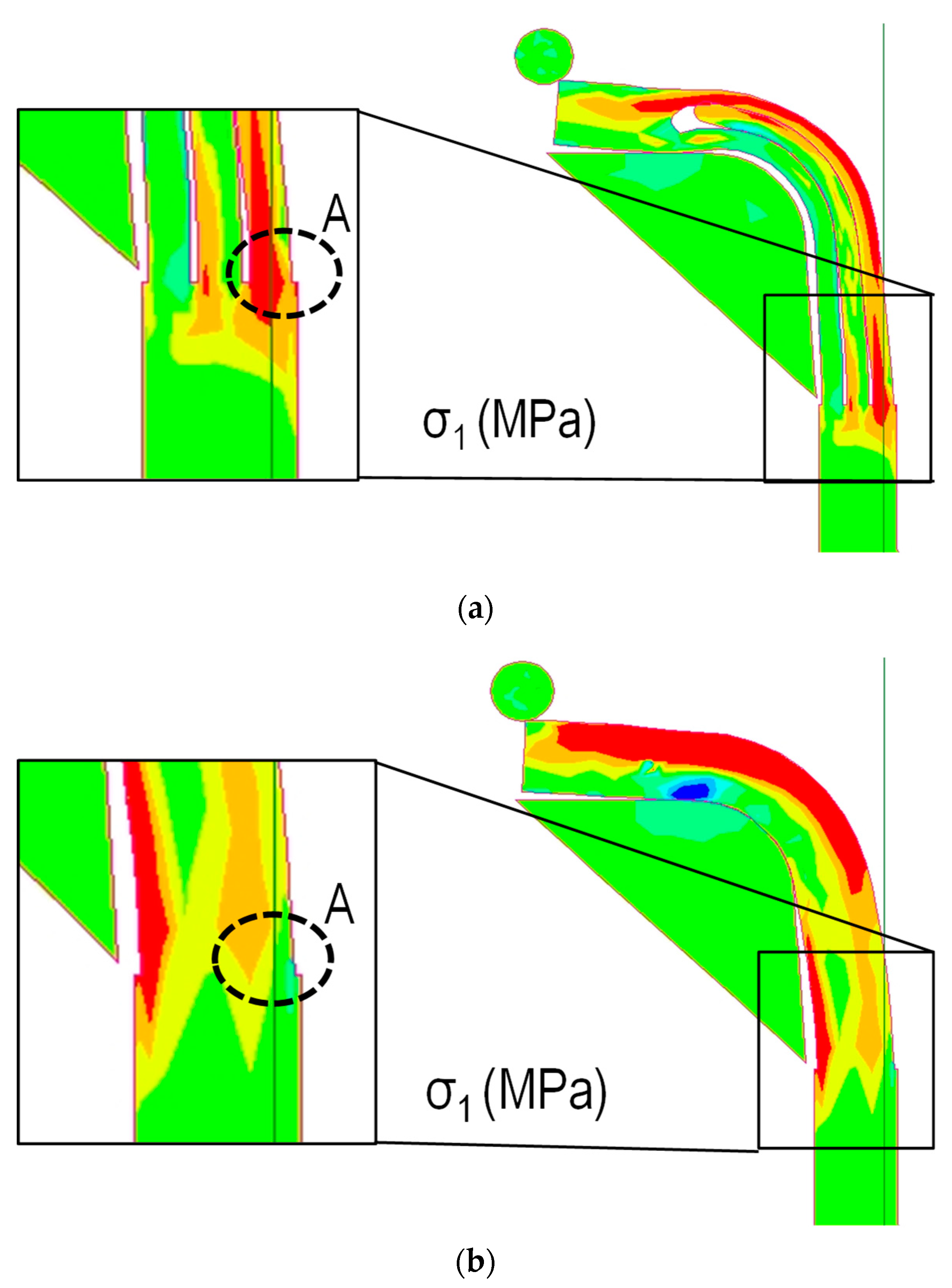
4.2. Stress Distribution in the Welded Area after Bending

Figure 13 shows the distribution of the maximum principal stress in the ground electrode at the end of the bending operation. Figure 13a,b corresponds, respectively, to a ground electrode with and without gap prior to bending. Of particular interest is area A. Effectively, cracks were observed experimentally in this area after bending. In the presence of gaps (Figure 13a), a significant maximum principle stress was predicted in the area where cracks were observed. However, the ground electrode without gap leads to a much smaller maximum principle stress in the same zone. As expected, the micro-movements allowed by the presence of gaps led to severe stress concentration at the outer border of the ground electrode.
The results of Section 2.2 revealed a strong relation between the presence of gaps after annealing and cracks after welding and bending. The results of Section 2.3 revealed the presence of a Cr2O3 layer leading to bad adherence between Cu and Inconel 601. Section 3.3 confirmed the presence of gaps after annealing and cooling, and the present section confirms the high stresses induced during bending under the presence of gaps. Thus, during annealing and cooling, the Inconel 601 undergoes irreversible (plastic) deformation. In the next section, a new ground electrode design avoiding the yielding of the Inconel 601 during annealing is recommended.

5. New Design of the Ground Electrode Avoiding Micro-Movements

5.1. Geometry and Finite Element Mesh

The thermo-mechanical model of the annealing treatment clearly showed bending of the Inconel due to larger thermal expansion of the copper core. Bending was allowed due to the open bottom of the ground electrode. Based on this finding, 1 mm of material was added to the bottom of the ground electrode (Figure 14a). The same approach as in Section 3 was adopted for annealing modelling. A 2D generalized plane strain model with an initial gap of 5 µm before annealing was used. The same mesh size was chosen (Figure 14b) and the same thermal loading was applied. The additional material was used to prevent gap formation during annealing. After annealing, it has to be cut.

5.2. Stress Distribution in the Electrode during Annealing

Figure 15a shows the distribution of axial stress at various heat treatment times (Figure 1c). The results correspond to an addition of 1 mm of material to the bottom of the ground electrode. In the Inconel 601 coating, only the two ends of the electrode are subjected to high stresses (at t2). The stress concentration at intermediate temperature t2 (red) is due to the copper core pushing the Inconel mantle. This corresponds to the thermal elongation of the copper in the x direction. At high temperature (t3), softening of the Inconel leads to a smaller stress in the same region. At room temperature (t4), compressive stresses in a small part of the additional material are found. Otherwise, the additional material undergoes small tensile stresses.
The additional material prevents bending and hence movement of the Inconel in the y direction. To prevent this movement, small tensile stresses, σyy, appear in the additional material (Figure 15b). At temperature (t2), the copper core pushes the Inconel. But, this load is equilibrated by tensile stresses in region A. However, a very small outward movement of the Inconel occurs close to the electrode bottom with yielding of the Inconel. But, the additional material (dashed area A) remains essentially elastic. Thus, when cooled to room temperature, the bottom part of the Inconel undergoes compressive stresses. For both materials, the stresses in region C are extremely small. Thus, the additional material leads to a satisfactory new stress distribution. No significant tensile stresses are found at room temperature.

5.3. Gaps versus Time

The aim of adding material was to decrease the final lateral gaps (Z2 to Z4). Z1 is not critical for the bending operation. Figure 16 shows a comparison between predicted gaps without (current geometry) and with additional material (new geometry). All gaps (Z2 to Z4) decreased significantly with the additional material. Moreover, all gaps at room temperature were smaller than the threshold of 10 µm. The new geometry leads to better stress distributions in the electrode and acceptable room temperature gaps.

6. Conclusions

Ground electrodes with Inconel 601 coating were analyzed. On the production line, cracking was observed on a small proportion (ppm) of electrodes with this new Inconel 601 coating. In the present paper, possible causes of cracking were analyzed experimentally and by mechanical models.
Two series of ground electrodes (with and without oil) were prepared and underwent the same production process. This original approach combined with advanced characterization techniques allowed us to identify gaps between Copper and Inconel 601 as the main cause of cracks. A thermo-mechanical model confirmed high stress concentrations during bending due to micro-movements allowed by gaps. A second thermo-mechanical model explained the presence of gaps by Inconel yielding during heat treatment. At this stage, the genuine combination of astute experimental procedure and well-chosen thermo-mechanical models allowed for the following simple conclusion: oil residues may lead to interface gaps, and the latter cause cracking during bending. Based on this knowledge, a completely new ground electrode design could be suggested. This new design is more cost-effective than advanced cleaning.

Author Contributions

Conceptualization, J.-M.B., H.K. and E.F.; methodology, C.T., J.-M.B., E.F., H.K. and C.B.; software, J.-M.B. and E.F.; validation, C.T., H.K., J.-M.B., E.F., C.B. and B.B.; formal analysis, C.T., J.-M.B., E.F. and H.K.; investigation, C.T., H.K., C.B. and B.B.; resources, J.-M.B., C.B. and B.B.; data curation, C.T., J.-M.B. and E.F.; writing—original draft preparation, C.T. and H.K.; writing—review and editing, C.T., H.K., E.F., B.B. and C.B.; visualization, C.T.; supervision, H.K., J.-M.B., E.F. and C.B.; project administration, J.-M.B. and C.B.; funding acquisition, J.-M.B. All authors have read and agreed to the published version of the manuscript.

Funding

This research received no external funding.

Acknowledgments

The authors are thankful to the “Association Nationale Recherche Technologie” and Federal Mogul Powertrain Ignition Products SAS for allowing this research project. Chawki Tahri prepared his PhD under the supervision of the following people; J.-M.B. and E.F. from “Ecole Nationale d’Ingénieurs de Saint-Etienne” and H.K. from “Mines Saint-Etienne”. B.B. (from “Ecole Centrale de Lyon”) helped with microscopic observations. We thank all the staff members from these institutions, which are all parts of “Université de Lyon”, for fruitful discussions.

Conflicts of Interest

The authors declare no conflict of interest.

References

  1. Javant, S.; Hosseini, S.V.; Alaviyoun, S.S. An Experimental Investigation of Spark Plug Temperature in Bi-fuel Engine and Its Effect on Electrode Erosion. Int. J. Automot. Eng. 2012, 2, 21–29. [Google Scholar]
  2. Lee, M.J.; Hall, M.; Ezekoye, O.A.; Matthews, R. Voltage, and Energy Deposition Characteristics of Spark Ignition Systems. J. Soc. Automot. Engine (SAE) 2006, 01, 231–243. [Google Scholar]
  3. Singh, H.; Sidhu, T.S.; Kalsi, S.S. Microstructure Study of Cold Sprayed 50%Ni–50%Cr Coating on Inconel-601. Surf. Eng. 2015, 31, 825–831. [Google Scholar] [CrossRef]
  4. Upadhyay, C.; Saurav, D.; Manoj, M.; Siba, S.M. An Experimental Investigation Emphasizing Surface Characteristics of Electro-Discharge-Machined Inconel 601. J. Braz. Soc. Mech. Sci. Eng. 2017, 39, 3051–3066. [Google Scholar] [CrossRef]
  5. Tahri, C.; Bertoni, C.; Klocker, H.; Feulvarch, E.; Bergheau, J.M. Numerical modeling of the resistance braze welded assembly of a Copper Inconel 601 ground electrode, and a Steel shell. Numer. Heat Transf. Part A Appl. 2020, 78, 1–20. [Google Scholar] [CrossRef]
  6. Lamineries Matthey. A Unit of Notz Metal SA, Montagu 38, Case Postale CH-2520, LA Neuveville. Available online: https://www.matthey.ch/en/alliages/cuivre/ (accessed on 8 July 2020).
  7. Lim, Y.Y.; Chaudhri, M.M. The effect of the indenter load on the nano-hardness of ductile metals: An experimental study on polycrystalline work hardened and annealed oxygen-free copper. Philos. Mag. A 1999, 2979–3000. [Google Scholar] [CrossRef]
  8. Buscail, H.; Perrier, S.; Josse, C. Oxidation Mechanism of the Inconel 601 Alloy at High Temperatures. Mater. Corros. 2011, 62, 416–422. [Google Scholar] [CrossRef]
  9. Special Metals, 3200 Riverside Drive Huntington, WV 25705-1771. Available online: www.specialmetals.com (accessed on 8 July 2020).
  10. Hewidy, M.S.; El-Taweel, T.A.; El-Safty, M.F. Modelling the Machining Parameters of Wire Electrical Discharge Machining of Inconel 601 Using RSM. J. Mater. Process. Technol. 2005, 169, 328–336. [Google Scholar] [CrossRef]
  11. Gonzalez-Rodriguez, J.G.; Salinas-Bravo, V.M.; Martinez-Villafane, A. Low-temperature stress corrosion cracking of alloy 601 in thiosulfate and chloride solutions. Corrosion 1999, 55, 1–38. [Google Scholar] [CrossRef]
  12. Nishikata, A.; Numata, H.; Tsuru, T. Electrochemistry of molten-salt corrosion. Mater. Sci. Eng. A Struct. 1991, 146, 15–31. [Google Scholar] [CrossRef]
  13. Vossen, J.P.T.; Plomp, L.; Dewit, J.H.W.; Rietveld, G. Corrosion behavior of stainless-steel and nickel-base alloys in molten-carbonate. J. Electrochem. Soc. 1995, 142, 3327–3335. [Google Scholar] [CrossRef]
  14. RRUFF Project, Department of Geosciences; University of Arizona: Tucson, AZ, USA; Available online: https://rruff.info/chem=cr%20/display=default/ (accessed on 8 July 2020).
  15. Bohua, Y.; Li, Y.; Nie, Y.; Mei, H. High Temperature Oxidation Behavior of a Novel Cobalt-Nickel-Base Superalloy. J. Alloys Compd. 2018, 765, 1148–1157. [Google Scholar] [CrossRef]
  16. Wallwork, G.R. The oxidation of alloys. Rep. Prog. Phys. 1976, 39, 401–485. [Google Scholar] [CrossRef]
  17. Garat, V.; Cloue, J.M.; Poquillon, D.; Andrieu, E. Influence of Portevin–Le Chatelier effect on rupture mode of alloy 718 specimens. J. Nucl. Mater. 2008, 375, 95–101. [Google Scholar] [CrossRef] [Green Version]
  18. SYSWELD™. User’s Manual; ESI Group: Paris, France, 2019. [Google Scholar]
  19. Khan, J.A.; Xu, L.; Chao, Y.-J.; Broach, K. Numerical Simulation of Resistance Spot Welding Process. Numer. Heat Transf. A 2000, 37, 425–446. [Google Scholar]
  20. Feulvarch, E.; Robin, V.; Bergheau, J.M. Thermometallurgical and Mechanical Modelling of Welding—Application to Multipass Dissimilar Metal Girth Welds. Sci. Technol. Weld. Join. 2011, 16, 221–231. [Google Scholar] [CrossRef]
  21. Feulvarch, E.; Bergheau, J.M. Modeling and Numerical Simulation of Resistance Spot Welding Process. In Encyclopedia of Thermal Stresses; Richard Hetnarski, B., Ed.; Springer: Dordrecht, The Netherlands, 2014; pp. 3112–3123. [Google Scholar] [CrossRef]
  22. Feulvarch, E.; Rogeon, P.; Carré, P.; Robin, V.; Sibilia, G.; Bergheau, J.M. Resistance Spot Welding Process: Experimental and Numerical Modeling of the Weld Growth Mechanisms with Consideration of Contact Conditions. Numer. Heat Transf. Part A Appl. 2006, 49, 345–367. [Google Scholar] [CrossRef]
  23. Bergheau, J.M.; Fortunier, R. Finite Element Simulation of Heat Transfer; ISTE & Wiley: London, UK, 2008; pp. 1–279. [Google Scholar] [CrossRef]
  24. Ishikawa, H. A thermoplastic solution for a circular solid cylinder subjected to heating and cooling. J. Therm. Stresses 1978, 1–2, 211–222. [Google Scholar] [CrossRef]
  25. Bengeri, M.; Mack, W. The Influence of the Temperature Dependence of the Yield Stress on the Stress Distribution in a Thermally Assembled Elastic-Plastic Shrink Fit. Acta Mech. 1994, 103, 243–257. [Google Scholar] [CrossRef]
  26. Pascon, F.; Cescotto, S.; Habraken, A.M. A 2.5D Finite Element Model for Bending and Straightening in Continuous Casting of Steel Slabs. Int. J. Numer. Methods Eng. 2006, 68, 125–149. [Google Scholar] [CrossRef]
  27. Yabo, G.; Pourboghrat, F. Fourier Series Based Finite Element Analysis of Tube Hydroforming—Generalized Plane Strain Model. J. Mater. Process. Technol. 2008, 197, 379–392. [Google Scholar] [CrossRef]
Figure 1. Manufacturing processes of a ground electrode. (a) Tamping of the copper in Inconel 601 cup, (b) cold working of the assembly, (c) annealing: temperature variation, (d) welding of the ground electrode to the steel shell [5], (1) and (2) indicate respectively the ground electrode and the welded zone, (e) bending inducing cracks (red rectangle), (f) final spark plug with crack in A.
Energies 13 03798 g001
Figure 2. (a) Spark plug, Tomographic (b,d) and light microscopic (c,e) observations of the welded zone after bending (zone A in (a)). After cold forming, the ground electrode (d,e) was cleaned prior to the annealing treatment under lab conditions (Section 2.1).
Energies 13 03798 g002
Figure 3. Measuring gaps: (a) typical cross-section after tomographic observation, (b) schematic representation of half of the ground electrode with exact locations of the gap measurements. Z1, Z2, Z3, and Z4 are microscopic gaps between Copper and Inconel, measured respectively at 7.5, 6.5, 3.5, and 0.4 mm from AA’.
Energies 13 03798 g003
Figure 4. Relation between observed gaps and cracking after bending. The admissible gaps are shown in blue. Lateral gaps larger than 10 µm systematically lead to cracking.
Energies 13 03798 g004
Figure 5. EDS mapping of the interface between copper and Inconel 601 after heat treatment of a sample prepared with oil. Mapping was done in the white rectangle.
Energies 13 03798 g005
Figure 6. Samples prepared with oil, interface damage (after heat treatment), and consequent cracking (after welding and bending): optical and SEM (Scanning Electron Microscopy) observations of damage close to the Cu–Inconel 601 interface. (g) Overall view of the sample. (af) Correspond to a sample after heat treatment (prior to welding and bending) and (h) corresponds to another sample (after bending). (ac) Copper–Inconel 601 interface in regions (A1, A2, A3), (de) copper–Inconel 601 interface in regions (B1, B2). (f) SEM observation of the interface in region B1. (h) Optical observation of the interface in region C after welding and bending with crack propagation through the Inconel 601.
Energies 13 03798 g006
Figure 7. Considered geometries (a) overall dimensions, (b) geometry without initial gap between the copper and Inconel, (c) with an initial gap of 5 µm, (d) zoom on the initial gap.
Energies 13 03798 g007
Figure 8. Finite element meshes for (a) generalized plane strain model and (b) three-dimensional (3D) model.
Energies 13 03798 g008
Figure 9. Axial stress, σxx, predicted by the three-dimensional (3D) and the two-dimensional (2D) generalized plane strain models with an initial gap of 5 µm.
Energies 13 03798 g009
Figure 10. Stress distribution in the sample. (a) Schematic electrode geometry with 4 lines (Li) defined in the Inconel coating. (b) Axial stress (σxx) in the Inconel along lines Li.
Energies 13 03798 g010
Figure 11. Evolution of the gaps during annealing. (a) Z1 at the top of the electrode, (b) Z2, Z3, and Z4 along the electrode’s axis.
Energies 13 03798 g011
Figure 12. Schematic representation of (a) the geometry of the workpiece and the bending tools, (b) boundary conditions, and (c) finite element meshes.
Energies 13 03798 g012
Figure 13. Maximum principal stress distribution (σ1) in the case (a) with gaps, and (b) without gaps at the interface between copper and Inconel 601.
Energies 13 03798 g013
Figure 14. (a) New geometry design, and (b) finite element meshes for generalized plane strain model.
Energies 13 03798 g014
Figure 15. 2D generalized plane strain model with 1 mm of additional material and with an initial gap of 5 µm. (a) Axial stress σxx, (b) stress σyy.
Energies 13 03798 g015
Figure 16. Influence of the additional material on final gap after annealing (Figure 1c) along the electrode’s axis.
Energies 13 03798 g016
Table 1. Chemical compositions of materials.
Wt (%)NickelCopperChromiumIronAluminumCarbonMagnesiumBismuthSulfurSilicon
Inconel 60158–63121–25181–1.70.11-0.0150.5
Copper-99.95-----<510−3--
Table 2. Gaps measured at room temperature after annealing by tomographic observations at locations Z1 and Z3 on 18 specimens with and 18 specimens without oil. Mean and standard deviation (SD) are shown.
With OilWithout Oil
Gap ValuesMeanSDMeanSD
Z1 (µm)1641288452
Z3 (µm)23116.12.9
Table 3. Physical properties of Inconel 601 [9].
T (°C)201002003004005006007008009001000
λ (W/m·k)11.212.714.316.017.719.521.022.824.426.127.8
C (J/Kg·k)448469498523548578603632657686712
α (10−6K−1)9.810.981112.2512.1911.113.1213.8813.361213.32
E (GPa)206202197191.2184.8178.2170.8161.3150.2137.9124.7
Rp02 (MPa)24023020017015015016016016012090
Table 4. Physical properties of copper [6].
T (°C)201002003004005006007008009001000
λ (W/m·k)410398386380360353348340335330320
C (J/Kg·k)386396400410415420440450460470500
α (10−6K−1)13.513.9614.2514.6215.4715.0914.0115.1214.8415.3519.17
E (GPa)117119114986850-----
Rp02 (MPa)1701601501209050-----
Table 5. Heat treatment-induced gaps at room temperature, simulation results, and optical measurements. Mean and standard deviation (SD) are shown
Location
Model versus ExperimentZ1Z2Z3Z4
2D plane strain model (µm)411.51540
Light optical
measurements (µm)
Mean29 2.11730.1
SD2.20.92.02.5
Table 6. Johnson–Cook’s law parameters for different materials [6,9].
A (MPa)B (MPa)nCm
Copper Cu-OF1704050.220.020.72
Inconel 60145017000.650.0171.3
Steel2445540.2170.00880.047

