Design and Implementation of High Order Sliding Mode Control for PEMFC Power System


1
Laboratory of Semiconductors and Functional Materials, Amar Telidji University of Laghouat, BP 37G, Laghouat 03000, Algeria
2
Engineering School of Vitoria, University of the Basque Country UPV/EHU, Nieves Cano 12, 1006 Vitoria, Spain
*
Author to whom correspondence should be addressed.
Energies 2020, 13(17), 4317; https://0-doi-org.brum.beds.ac.uk/10.3390/en13174317
Submission received: 19 July 2020
/
Revised: 12 August 2020
/
Accepted: 18 August 2020
/
Published: 20 August 2020
(This article belongs to the Special Issue Polymer Electrolyte Membrane Fuel Cell Systems)
Abstract
:Fuel cells are considered as one of the most promising methods to produce electrical energy due to its high-efficiency level that reaches up to 50%, as well as high reliability with no polluting effects. However, scientists and researchers are interested more in proton exchange membrane fuel cells (PEMFCs). Thus, it has been considered as an ideal solution to many engineering applications. The main aim of this work is to keep the PEMFC operating at an adequate power point. To this end, conventional first-order sliding mode control (SMC) is used. However, the chattering phenomenon, which is caused by the SMC leads to a low control accuracy and heat loss in the energy circuits. In order to overcome these drawbacks, quasi-continuous high order sliding mode control (QC-HOSM) is proposed so as to improve the power quality and performance. The control stability is proven via the Lyapunov theory. The closed-loop system consists of a PEM fuel cell, a step-up converter, a DSPACE DS1104, SMC and QC-HOSM algorithms and a variable load resistance. In order to demonstrate the effectiveness of the proposed control scheme, experimental results are compared with the conventional SMC. The obtained results show that a chattering reduction of 84% could be achieved using the proposed method.
1. Introduction
Under the decrease of fossil energy, the process of obtaining the necessary power to cover the human needs is facing many problems. These have been identified in terms of cost, reducing environmental pollution and lack of energy sources. Hence, scientists and researchers are aspiring to balance these three directions in order to obtain the best solution and optimal results [1]. Fuel cells are an ideal solution that can be used in many engineering fields, including transportation [2,3,4,5], aircraft [6,7] and distributed generation [8,9,10], as well as stationary and mobile applications [11,12,13,14]. One of the most commonly used fuel cells is the proton exchange membrane fuel cell (PEMFC). It is characterised by high power density, low-temperature operation (fast start-up), lightweight and zero pollution [15,16]. However, the PEM fuel cells have a nonlinear characteristic, as their performance changes with different operating conditions (pressure gases and temperature), where these latter lead to significant changes in the PEMFC output power [17]. Therefore, to keep the PEMFC working at an adequate power point, different approaches are suggested. For instance, in Derbeli et al. [18], a proportional-integral (PI) and an SMC were proposed to maintain the fuel cell runs at an efficient power point. The PI is characterised by its simplicity, but it is affected by the changes in the external transactions and disturbances. Comparative results with the SMC have demonstrated that this latter is characterised by its durability, especially against changes in external factors and disturbances, and also its ability to control the nonlinear systems. In Choe et al. [19], an adequate power point was achieved through the use of proportional-integral-derivative (PID). This latter was designed to control the fuel cell by adjusting the pulse width modulation (PWM) of the boost converter. Results have demonstrated that the objective is attained through the proposed method with improved dynamics and high tracking performance. In Andujar et al. [20], an analysis technique based on the small-signal model (SSM) has been applied on a linearised fuel cell. However, the controller’s parameters are not suitable for all operating conditions, and they must be manually changed for each variation. In Ahmadi et al. [21], a maximum power point tracking (MPPT) based on a particle swarm optimization (PSO) controller has been used to extract the maximum power from the fuel cell. Comparative results with perturb and observe (P&O) and SMC have shown the effectiveness of the proposed algorithm in terms of precision, response time and ripple reduction. Authors of [22] used a variable step size fuzzy MPPT technique so as to track the maximum output power from the PEMFC. Simulation results have demonstrated that a ripple reduction of up to 70.93% could be achieved. In Hahm et al. [23], an incremental conductance-based sliding mode (ICSM) was applied for a hybrid PV/PEMFC system aiming to provide a usable voltage to feed a brushless DC motor. The proposed algorithm was compared with P&O, incremental conductance (INC) and variable-step INC. Good results, such as high power intensity, fast response time, good durability and viability, are obtained using the proposed ICSM algorithm. Authors of [24], used a super-twisting algorithm (STA) to overcome the drawbacks of the conventional SMC. Comparative results have shown the ability of STA in minimising the disturbances and the chattering phenomenon. In Luta and Raji. [25], a fuzzy logic (FL) based on partial swarm optimisation was designed so as to maintain the fuel cell operating at an adequate power point. However, high power overshoot of is obtained. In Becherif and Hissel. [26], an MPPT based on P&O was applied on a PEM fuel cell system integrated with motocompressor. The results have shown that the production power can be enhanced by more than 10% using the proposed technique. Authors of [27], used two MPPT approaches based on fuzzy logic control (FLC) and P&O. Comparative results have shown the effectiveness of the proposed FLC in terms of reducing the unwanted oscillations around the operating power point. In Reddy and Sudhakar. [28], an MPPT-based neural network (NN) and FLC are used to track the maximum power for different operating temperatures. The results have shown that the proposed neural network MPPT has tracked the maximum power point faster than the FLC. However, although authors of [18,19,20,21,22,23,24,25,26,27,28] proposed advanced algorithms, only simulation work has occurred. Therefore, with respect to state-of-the-art, a real-time implementation of a high order sliding mode based on QC is proposed to keep the fuel cell operating at an adequate power point. Aiming to extract the maximum power from the fuel cell, the author firstly designed an MPPT-based QC-HOSM algorithm. However, due to the integrated security system which protects the stack from damage, the implementation of the MPPT could be a hard task. Thereby, the authors have constructed an operating zone at which up to more than 91% of the maximum generated power could be extracted. The effectiveness of the proposed algorithm is demonstrated through a comparison study with conventional SMC. In addition, the stability of QC-HOSM is proven via the Lyapunov theory.
This paper is arranged as follows: Section 2 presents the model of the PEMFC. It includes the properties of hydrogen cells and equations that explain their actions. The proposed QC-HOSM algorithm and the stability proof, as well as the step-up converter operating principle, are presented in Section 3. Section 4 explains the experimental system. The results and discussions are presented in Section 5. Finally some conclusions are presented in Section 6.
2. Proton Exchange Membrane (PEM) Fuel Cell
Proton exchange membrane (PEM) fuel cell is a device that is capable of converting chemical energy into electrical energy. It is considered as one of the best and smallest species thanks to the energy it produces. As shown in Figure 1, a PEM fuel cell consists of an anode and cathode supplied with hydrogen and oxygen, respectively. These two elements are separated by an electrolyte and two catalysts, that are usually made of platinum [29,30,31]. When the hydrogen enters the cell, the catalyst of the anode separates it into protons and electrons. The membrane (Electrolyte) allows only the protons to pass while the blocked electrons will pass through the bipolar plates, and generates a constant electric direct current (DC). At the catalyst of the cathode, the electrons and the protons are combined with the presence of the oxygen to form water and heat [32,33]. The reaction equations are given in Equation (1)–(3) [27]:
The Nernst equation, which is given in Equation (4), shows the relationship between the open-circuit voltage in the standard conditions (), and the voltage of the fuel cell (), in different temperatures and pressures [34,35,36,37,38].
where, , , , , T, R and F, are respectively the entropy losses (kJ/molK), the Gibbs free energy (J/mol), inlet oxygen gas pressure at the cathode, inlet hydrogen gas pressure at the anode, the fuel cell operating temperature (kelvin), the universal gas constant (J/Kmole) and the Faraday’s constant (C/mol) [35]. By substituting these parameters by their values, Equation (4) becomes as Equation (5) [34]:
The fuel cell terminal voltage is given in Equation (6) [34,35,36,37,38]:
where, , , are the drop in the open-circuit voltage of the fuel cell. They are also called over-voltage, overpotential or losses.
The activation losses () occurs due to the energy of interaction between gases, especially oxygen. Its equation is given in Equation (7) [36]:
where, are parametric coefficients, and is the oxygen concentration in catalysts [36].
The ohmic losses () occur due to the creation of ohmic resistance in front of the transit of electrons that takes place in the bipolar plates , and due to the transit of protons through the electrolyte [36]. The calculation of these losses can be done with the Ohm’s law as given in Equation (8) [37]:
3. Electronic Power Interface
3.1. Step-Up Converter
The step-up converter, also named DC-DC boost converter, is widely used in many applications such as photovoltaic, fuel cells and wind power systems [39,40,41,42]. As shown in Figure 2, a DC-DC boost converter consists of inductance (L), switching element (transistor), a diode (D) and a capacitor (C). It is an adaptation stage where it acts as an interface between the two elements, source and load. Thus, it takes the input voltage and converts it to a higher voltage output. In addition, it ensures through a control action, the extraction of the maximum power from the source. To this end, the stack voltage must be set to equal the required value at which the maximum power could be attained.
The relationship between the input and output voltage can be determined as Equation (11), while D is the duty cycle [43].
DC-DC converter can operate in two different modes: continuous conduction mode (CCM) and discontinuous conduction mode (DCM). However, in this work, the DC-DC converter is designed based on the CCM. Figure 3 shows the signals of the voltage and current of the inductance (L) [44]. Thus, the operation of the CCM is divided into two distinct intervals. The first one, when the switch K is “on” for a period of time , the current passes from the source through the inductance, where it increases linearly to its peak . The second one, when K is “off” for a period of time , the current flows through the inductance, the diode, the capacitor and the load. During this time, the power stored in the inductance will be converted to the load. In this case, the output voltage will be higher than the input voltage.
By using the Kirchhoff law in terms of switching command, the description of the boost converter state-space can be represented as Equation (12) [35]:
where , represents , represents and u represents the converter control input.
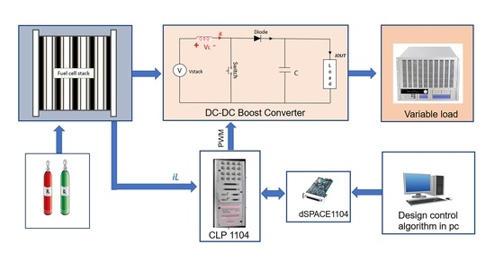
The closed-loop system including the PEMFC, the converter, the controller and the load, are presented in Figure 4
3.2. Quasi-Continuous High Order Sliding Mode Control (QC-HOSM)
The higher-order sliding mode has recently been developed by [45] according to the principle of homogeneity [46]. This type of control belongs to the theory of systems with variable structure. It ensures the convergence of the state towards the origin in finite time. In this work, the QC-HOSM has been applied to drive the step-up converter to hold the PEMFC at an optimal power point and to ensure the reduction of the chattering phenomenon, as well as to prolong the PEMFC lifetime. In order to design the controller, we consider the nonlinear system described by Equation (13):
where, and are nonlinear functions, u is a discontinuous and bounded command depending on the state x and time t. The tracking error is defined by Equation (14), while represents the desired current.
The general formula of the sliding surface is defined by Equation (15) [47]:
where n is the system’s relative degree (), is a positive constant chosen by the operator. It should be noted that a large value of implies a fast system response. However, very fast response can lead to overshoot or even system instability. On the other hand, low value of implies a slow system response but this leads to decrease the overshoot. Thereby, the sliding surface also can be written as Equation (16):
To design the QC-HOSM, the uncertain second-order system should be written as Equation (18)
where is the command derivative, and are determined by Equation (19):
Assuming that and are bounded as Equation (20) [48]:
where , , are positive constants. The command law is the sum of two components, the equivalent component, and the discontinuous component. It can be written as Equation (21):
where, is the equivalent control proposed by [47]. It is deduced from the relation of . Its main role is ensuring that the system hits the sliding surface. The equivalent control can be expressed as Equation (22):
is the switching control. Its key aim is to ensure the stability and the convergence by holding the system on the sliding surface. In this work, we propose the switching control as Equation (23):
where, the parameter could be determined using the condition given in Equation (24) [48].
In order to prove the stability, the following Lyapunov function is proposed: . The time derivative of this function is calculated in Equation (25).
F and , therefore, according to the Lyapunov theory, the PEMFC system is stable.
4. Experimental Device Overview
The principal objective of this section is to validate the proposed QC-HOSM controller over a real fuel cell system. First, the QC-HOSM is configured and installed in the Matlab/Simulink environment, and then, it is loaded into the DSP card system for real-time operation. The experimental test bench, including the FC50 fuel cell, programmable load resistance (BK-PRECISION), dSPACE DS1104 card, workstation computer and step-up converter, are presented in Figure 5.
The fuel cell FC50 stack characteristics are listed in Table 1. It is composed of ten cells that are able to generate power up to more than 50 W at DC voltage equal to 5 V. It is alimented by a hydrogen cylinder, which is linked to a manometer to reduce the inlet pressure. It also consists of an external ventilator that provides oxygen and cooling to the stack. The controller board 9 is the main component of the fuel cell auxiliaries. It plays the role of the distribution centre for all the data among the fuel cell components such as the software, the hydrogen flow meter, the fans and the temperature sensors. It has many functions such as measuring the system parameter, controlling the fans, connecting/disconnecting load by integrated relay, communicating to the PC, providing simple operation, protect the stack from short circuits and over-loads, as well as ensuring the safety of the PEMFC.
The control of continuous systems in real-time is done using a PC connected to the dSPACE DS1104 card, which has a powerful central processor MPC8240 with a frequency speed up to 250 MHZ. It also contains eight digital to analogue converters (DAC) and eight analogues to digital converters (ADC). These converters are related to a specific signal. As shown in Figure 6, whose supplied voltage is between −10V and +10V. The dSPACE DS1104 uses two types of ADC: four multiplexed ADC converters (ADC-C1 to ADC-C4) for the channels signals (ADCH1 to ADCH4), with 16-bit resolution and signal-to-noise ratio SNR > 80 dB and four ADC converters (ADC-C5 to ADC-C8) for the channels signals (ADCH5 to ADCH8), with 12-bit resolution and signal-to-noise ratio SNR > 70 dB. In addition to that, it has several interfaces, including digital input and output as well as incremental encoders. It also has a DSP slave, the TMS320F240 DSP, which is used to generate the PWM signals. Where this latter is used to control the step-up DC/DC converter. The control process is built through the following three stages: construction of the control system using Simulink blocks, simulation of the system to display the results in different scenarios and finally the execution of the model in real-time through the DS1104 card.
The step-up DC/DC converter is constructed by the research-group-TEP192, Huelva University, Spain. Its characteristics are listed in Table 2.
5. Results and Discussion
Figure 7 shows the FC50 current–potential (I–V) and current–power (I–P) characteristics curves for different operating temperatures. According to this figure, it is notable that the FC50 performance is improved by enhancing the temperature from 20 to 46 . This could be interpreted by the raise of the membrane conductivity. However, for temperatures up to more than 46 , the membrane starts to dry, which causes a lack of the relative humidity. As a consequence, a drop in the fuel cell performance has occurred.
Aiming to hold the PEM fuel cell operating at an adequate power point, the MPPT algorithms are used. However, due to the integrated security system which protects the stack from damage, the implementation of the MPPT could be a hard task. Hence, it prevents the fuel cell to operate with high currents in the concentration zone at which the locale of the maximum power. In other words, the operating current which corresponds to the MPP could be near to the maximum generated current at which the security system turns the fuel cell off so as to protect the membrane from the damage. Therefore, it is not possible to achieve the MPP value experimentally. To deal with this condition, the authors have constructed an operating zone, as shown in Figure 7, at which up to more than 91% of the maximum generated power could be extracted.
In order to reveal the effectiveness, and the performance of the QC-HOSM control, load resistances are varied from 20 to 50 at time s, and from 50 to 20 at time s. Furthermore, to find out the advantages of the proposed QC-HOSM algorithm, a comparison study is done with conventional first-order SMC. The proposed controller coefficients used in this work are enlisted in Table 3.
Thus, Figure 8a shows the duty cycle signal for both algorithms. It is noticed that both of the algorithms show a soft and smooth rise to the desired reference value. However, it is clearly shown that the proposed QC-HOSM algorithm effectively overcomes the drawbacks of the conventional first SMC by reducing its chattering phenomenon. Figure 8b,c show the FC50 current and voltage signals. The effectiveness of both algorithms when experiencing significant changes in load resistance is clearly demonstrated at s and s. Hence, at the instant s, the SMC shows an undershoot current of 1 A, and an overshoot voltage of V. For the instant 5 s, an overshoot current of A, and an undershoot voltage of 0.96V. On the other hand, at the instant s, the QC-HOSM algorithm shows an undershoot current of , and an overshoot voltage of 1 V. For the instant s, an overshoot current of A, and an undershoot voltage of V. However, these undershoots and overshoots appeared only for short durations and then, they converge to the reference value. Thus, at the instant s, the response time of the SMC and the QC-HOSM are only s and s, while at s they are s and s, respectively. Therefore, high robustness against load variations is achieved using both algorithms. The effectiveness of the proposed QC-HOSM over the conventional SMC appears in its capability to reduce the oscillations. Hence, chattering reduction of could be attained. Figure 8d shows the trajectory of the generated power. It is obvious that the operating zone, which is already presented in Figure 7, is achieved with high robustness and global stability of the closed-loop system. The chattering magnitude using the conventional SMC is in the range of 20 W and W, while it is only in the range of W and W using the proposed QC-HOSM algorithm. It is therefore proven that the proposed algorithm succeeded in decreasing the chattering effect, which will improve as a consequence of the fuel cell efficiency, lifetime and the dynamic system behaviour.
Figure 9 shows the behaviour of the step-up DC-DC converter output voltage, output current and output power, as well as the load resistance variation. According to this figure, despite facing sharp resistance variation, the QC-HOSM shows gradual and smooth movements to the desired voltage at which the system runs in the operating zone. Furthermore, high performances such as low response-time, great robustness, high precision, as well as outstanding dynamic behaviour, are achieved.
According to these results, it is noticed that the SMC and QC-HOSM show a good behaviour against load resistance variations. However, it is clearly seen that the advantage of the QC-HOSM is its effectiveness to reduce the unwanted oscillation (chattering effect) with significant value. Thus, a chattering reduction of 84% is obtained which, as a consequence, will increase the accuracy and the overall system efficiency.
6. Conclusions
The objective of this paper is to improve the performance of the PEMFC system by using a specific control algorithm. The model of the entire PEMFC system has been established and studied so as to facilitate its analysis. The PEMFC is interfaced by a high step-up DC-DC converter. This study also presents the application of two non-linear control command approaches for regulating the PEMFC current. The first approach is the conventional SMC. However, although this latter has given satisfactory results in terms of control robustness in a real-time, its chattering phenomenon still bears a significant problem since it reduces the accuracy and the overall system efficiency. However, to overcome these drawbacks, a QC-HOSM is proposed so as to maintain the robustness of the conventional SMC and to enhance the efficiency of the overall system by decreasing the chattering phenomenon. It has been demonstrated through experimental results that the proposed QC-HOSM effectively keeps the system operating at the adequate power point even under large load resistance variation. In addition, it has been clearly proven the effectiveness of the proposed algorithm over the conventional SMC. Thus, a reduction of 84% in the chattering effect is achieved which, accordingly, will increase the accuracy and the overall system efficiency.
Author Contributions
Conceptualization, M.Y.S. and M.D.; methodology, M.Y.S. and M.D.; software, M.Y.S. and M.D.; validation, M.D. and O.B.; formal analysis, M.Y.S. and M.D.; investigation, M.Y.S. and M.D.; resources, O.B.; data curation, M.Y.S. and M.D.; writing—original draft preparation, M.Y.S. and M.D.; writing—review and editing, M.Y.S., M.D., O.B.; visualization, M.Y.S. and M.D.; supervision, O.B., A.C.; project administration, O.B.; funding acquisition, O.B. All authors have read and agreed to the published version of the manuscript.
Funding
This work was partially supported by Eusko Jaurlaritza/Gobierno Vasco [grant number SMAR3NAK ELKARTEK KK-2019/00051]; the Provincial Council of Alava (DFA) [grant number CONAVAUTIN 2] (Collaboration Agreement).
Acknowledgments
The authors would like to acknowledge the algerien government and the UPV/EHU for supporting this work.
Conflicts of Interest
The authors declare no conflict of interest.
Abbreviations
The following abbreviations are used in this manuscript:
| PEMFC | proton exchange membrane fuel cell |
| SMC | sliding mode control |
| QC-HOSM | quasi-continuous high order sliding mode controllers |
| DSPACE | Digital Signal Processing and Control Engineering |
| PI | proportional-integral |
| PID | proportional-integral derivative |
| PWM | pulse width modulation |
| SSM | small-signal model |
| MPPT | maximum power point tracking |
| PSO | particle swarm optimisation |
| P & O | perturb and observe |
| ICSM | incremental conductance sliding mode |
| INC | incremental conductance |
| STA | super twisting algorithm |
| FL | fuzzy logic |
| PV | photovoltaic |
| FLC | fuzzy logic controller |
| NN | neural networks |
| DC | direct current |
| CCM | continuous conduction mode |
| DCM | discontinuous conduction mode |
| DAC | digital to analog converter |
| ADC | analog to digital converter |
References
- Wang, F.C.; Lin, K.M. Impacts of Load Profiles on the Optimization of Power Management of a Green Building Employing Fuel Cells. Energies 2019, 12, 57. [Google Scholar] [CrossRef] [Green Version]
- Niu, W.; Song, K.; Xiao, Q.; Behrendt, M.; Albers, A.; Zhang, T. Transparency of a Geographically Distributed Test Platform for Fuel Cell Electric Vehicle Powertrain Systems Based on X-in-the-Loop Approach. Energies 2018, 11, 2411. [Google Scholar] [CrossRef] [Green Version]
- Raga, C.; Barrado, A.; Miniguano, H.; Lazaro, A.; Quesada, I.; Martin-Lozano, A. Analysis and Sizing of Power Distribution Architectures Applied to Fuel Cell Based Vehicles. Energies 2018, 11, 2597. [Google Scholar] [CrossRef] [Green Version]
- Shtessel, Y.B.; Ghanes, M.; Ashok, R.S. Hydrogen Fuel Cell and Ultracapacitor Based Electric Power System Sliding Mode Control: Electric Vehicle Application. Energies 2020, 13, 2798. [Google Scholar] [CrossRef]
- González Palencia, J.C.; Nguyen, V.T.; Araki, M.; Shiga, S. The Role of Powertrain Electrification in Achieving Deep Decarbonization in Road Freight Transport. Energies 2020, 13, 2459. [Google Scholar] [CrossRef]
- Elitzur, S.; Rosenband, V.; Gany, A. On-board hydrogen production for auxiliary power in passenger aircraft. Int. J. Hydrogen Energy 2017, 42, 14003–14009. [Google Scholar] [CrossRef]
- Yaacoubi, S.; McKeon, P.; Ke, W.; Declercq, N.F.; Dahmene, F. Towards an Ultrasonic Guided Wave Procedure for Health Monitoring of Composite Vessels: Application to Hydrogen-Powered Aircraft. Materials 2017, 10, 1097. [Google Scholar] [CrossRef] [Green Version]
- Mohamed, A.-A.A.; Ali, S.; Alkhalaf, S.; Senjyu, T.; Hemeida, A.M. Optimal Allocation of Hybrid Renewable Energy System by Multi-Objective Water Cycle Algorithm. Sustainability 2019, 11, 6550. [Google Scholar] [CrossRef] [Green Version]
- Al-Sakkaf, S.; Kassas, M.; Khalid, M.; Abido, M.A. An Energy Management System for Residential Autonomous DC Microgrid Using Optimized Fuzzy Logic Controller Considering Economic Dispatch. Energies 2019, 12, 1457. [Google Scholar] [CrossRef] [Green Version]
- Atawi, I.E.; Kassem, A.M.; Zaid, S.A. Modeling, Management, and Control of an Autonomous Wind/Fuel Cell Micro-Grid System. Processes 2019, 7, 85. [Google Scholar] [CrossRef] [Green Version]
- Wilberforce, T.; Alaswad, A.; Palumbo, A.; Dassisti, M.; Olabi, A.G. Advances in stationary and portable fuel cell applications. Int. J. Hydrogen Energy 2016, 41, 16509–16522. [Google Scholar] [CrossRef] [Green Version]
- Bansal, S.; Zong, Y.; You, S.; Mihet-Popa, L.; Xiao, J. Technical and Economic Analysis of One-Stop Charging Stations for Battery and Fuel Cell EV with Renewable Energy Sources. Energies 2020, 13, 2855. [Google Scholar] [CrossRef]
- Boulmrharj, S.; Khaidar, M.; Bakhouya, M.; Ouladsine, R.; Siniti, M.; Zine-dine, K. Performance Assessment of a Hybrid System with Hydrogen Storage and Fuel Cell for Cogeneration in Buildings. Sustainability 2020, 12, 4832. [Google Scholar] [CrossRef]
- Farzaneh, H. Design of a Hybrid Renewable Energy System Based on Supercritical Water Gasification of Biomass for Off-Grid Power Supply in Fukushima. Energies 2019, 12, 2708. [Google Scholar] [CrossRef] [Green Version]
- Derbeli, M.; Mrad, I.; Sbita, L.; Barambones, O. PEM fuel cell efficiency boosting—Robust MPP tracking. In Proceedings of the 2018 9th International Renewable Energy Congress (IREC), Hammamet, Tunisia, 20–22 March 2018; pp. 1–5. [Google Scholar]
- Derbeli, M.; Charaabi, A.; Barambones, O.; Sbita, L. Optimal Energy Control of a PEM Fuel Cell/Battery Storage System. In Proceedings of the 10th International Renewable Energy Congress (IREC), Sousse, Tunisia, 26–28 March 2019; pp. 1–5. [Google Scholar]
- José-Luis, C.R.; Antonio, J.B.; Francisca, S.; José Luis, C.R.; José, M.A. Fuel Cell Output Current Prediction with a Hybrid Intelligent System. Complexity 2019, 2019, 1–10. [Google Scholar]
- Derbeli, M.; Barambones, O.; Farhat, M.; Sbita, L. Efficiency Boosting for Proton Exchange Membrane Fuel Cell Power System Using New MPPT Method. In Proceedings of the 10th International Renewable Energy Congress (IREC), Sousse, Tunisia, 26–28 March 2019; pp. 1–4. [Google Scholar]
- Choe, S.Y.; Lee, J.G.; Ahn, J.W.; Baek, S.H. Integrated modeling and control of a PEM fuel cell power system with a PWM DC/DC converter. J. Power Sources 2007, 164, 614–623. [Google Scholar] [CrossRef]
- Andujar, J.; Segura, F.; Vasallo, M. A suitable model plant for control of the set fuel cell- DC/DC converter. Renew. Energy. 2008, 33, 813–826. [Google Scholar] [CrossRef]
- Ahmadi, S.; Abdi, S.; Kakavand, M. Maximum power point tracking of a proton exchange membrane fuel cell system using PSO-PID controller. Int. J. Hydrog. Energy 2017, 42, 20430–20443. [Google Scholar] [CrossRef]
- Harrag, A.; Messalti, S. How fuzzy logic can improve PEM fuel cell MPPT performances? Int. J. Hydrog. Energy 2018, 43, 537–550. [Google Scholar] [CrossRef]
- Hahm, J.; Kang, H.; Baek, J.; Lee, H.; Park, M. Design of incremental conductance sliding mode MPPT control applied by integrated photovoltaic and proton exchange membrane fuel cell system under various operating conditions for BLDC motor. Int. J. Photoenergy 2015, 2015, 1–14. [Google Scholar] [CrossRef] [Green Version]
- Derbeli, M.; Farhat, M.; Barambones, O.; Sbita, L. Control of PEM fuel cell power system using sliding mode and super-twisting algorithms. Int. J. Hydrogen Energy 2017, 42, 8833–8844. [Google Scholar] [CrossRef]
- Luta, D.N.; Raji, A.K. Fuzzy Rule-Based and Particle Swarm Optimisation MPPT Techniques for a Fuel Cell Stack. Energies 2019, 12, 936. [Google Scholar] [CrossRef] [Green Version]
- Becherif, M.; Hissel, D. MPPT of a PEMFC based on air supply control of the motocompressor group. Int. J. Hydrogen Energy 2010, 22, 12521–12530. [Google Scholar] [CrossRef]
- Derbeli, M.; Sbita, L.; Farhat, M.; Barambones, O. Proton exchange membrane fuel cell—A smart drive algorithm. In Proceedings of the 2017 International Conference on Green Energy Conversion Systems(GECS), Hammamet, Tunisia, 23–25 March 2017; pp. 1–5. [Google Scholar]
- Reddy, K.J.; Sudhakar, N. High voltage gain interleaved boost converter with neural network based MPPT controller for fuel cell based electric vehicle applications. IEEE Access 2018, 6, 3899–3908. [Google Scholar] [CrossRef]
- Derbeli, M.; Farhat, M.; Barambones, O.; Sbita, L. A robust MPP tracker based on backstepping algorithm for Proton Exchange Membrane Fuel Cell power system. In Proceedings of the 2017 11th IEEE International Conference on Compatibility, Power Electronics and Power Engineering (CPE-POWERENG), Cadiz, Spain, 4–6 April 2017; pp. 424–429. [Google Scholar]
- Li, C.; Sallee, A.; Zhang, X.; Kumar, S. Electrochemical Hydrogenation of Acetone to Produce Isopropanol Using a Polymer Electrolyte Membrane Reactor. Energies 2018, 11, 2691. [Google Scholar] [CrossRef] [Green Version]
- Bai, B.; Chen, Y.T. Simulation of the Oxygen Reduction Reaction (ORR) Inside the Cathode Catalyst Layer (CCL) of Proton Exchange Membrane Fuel Cells Using the Kinetic Monte Carlo Method. Energies 2018, 11, 2529. [Google Scholar] [CrossRef] [Green Version]
- Zhang, X.; Higier, A.; Zhang, X.; Liu, H. Experimental Studies of Effect of LandWidth in PEM Fuel Cells with Serpentine Flow Field and Carbon Cloth. Energies 2019, 12, 471. [Google Scholar] [CrossRef] [Green Version]
- Bahrebar, S.; Blaabjerg, F.; Wang, H.; Vafamand, N.; Khooban, M.H.; Rastayesh, S.; Zhou, D. A novel type-2 fuzzy logic for improved risk analysis of proton exchange membrane fuel cells in marine power systems application. Energies 2018, 11, 721. [Google Scholar] [CrossRef] [Green Version]
- Corrêa, J.M.; Farret, F.A.; Canha, L.N.; Simoes, M.G. An electrochemical-based fuel-cell model suitable for electrical engineering automation approach. IEEE Trans. Ind. Electron. 2004, 51, 1103–1112. [Google Scholar] [CrossRef]
- Derbeli, M.; Barambones, O.; Ramos-Hernanz, J.A.; Sbita, L. Real-time implementation of a super twisting algorithm for PEM fuel cell power system. Energies 2019, 12, 1594. [Google Scholar] [CrossRef] [Green Version]
- Derbeli, M.; Farhat, M.; Barambones, O.; Sbita, L. Control of Proton Exchange Membrane Fuel Cell (PEMFC) power system using PI controller. In Proceedings of the 2017 International Conference on Green Energy Conversion Systems (GECS), Hammamet, Tunisia, 23–25 March 2017; pp. 1–5. [Google Scholar]
- Derbeli, M.; Barambones, O.; Sbita, L. A Robust Maximum Power Point Tracking Control Method for a PEM Fuel Cell Power System. Appl. Sci. 2018, 8, 2449. [Google Scholar] [CrossRef] [Green Version]
- Derbeli, M.; Sbita, L.; Farhat, M.; Barambones, O. PEM fuel cell green energy generation—SMC efficiency optimization. In Proceedings of the 2017 International Conference on Green Energy Conversion Systems (GECS), Hammamet, Tunisia, 23–25 March 2017; pp. 1–5. [Google Scholar]
- Ma, M.; Liu, X.; Lee, K.Y. Maximum Power Point Tracking and Voltage Regulation of Two-Stage Grid-Tied PV System Based on Model Predictive Control. Energies 2020, 13, 1304. [Google Scholar] [CrossRef] [Green Version]
- Syahputra, R.; Soesanti, I. Performance Improvement for Small-Scale Wind Turbine System Based on Maximum Power Point Tracking Control. Energies 2019, 12, 3938. [Google Scholar] [CrossRef] [Green Version]
- Bhaskar, M.S.; Padmanaban, S.; Holm-Nielsen, J.B. Double Stage Double Output DC–DC Converters for High Voltage Loads in Fuel Cell Vehicles. Energies 2019, 12, 3681. [Google Scholar] [CrossRef] [Green Version]
- Derbeli, M.; Barambones, O.; Farhat, M.; Ramos-Hernanz, J.A.; Sbita, L. Robust high order sliding mode control for performance improvement of PEM fuel cell power systems. Int. J. Hydrogen Energy 2020.
- Gosumbonggot, J.; Fujita, G. Partial shading detection and global maximum power point tracking algorithm for photovoltaic with the variation of irradiation and temperature. Energies 2019, 12, 202. [Google Scholar] [CrossRef] [Green Version]
- Saharia, B.J.; Talukdar, B.K. Theoretical study on performance constraints of a DC-DC buck-boost converter. In Proceedings of the 2015 International Conference on Energy, Power and Environment: Towards Sustainable Growth (ICEPE), Shillong, India, 12–13 June 2015; pp. 1–4. [Google Scholar]
- Levant, A. Quasi-continuous high-order sliding-mode controllers. IEEE Trans. Autom. Control 2005, 50, 1812–1816. [Google Scholar] [CrossRef]
- Levant, A. Homogeneity approach to high-order sliding mode design. Automatica 2005, 41, 823–830. [Google Scholar] [CrossRef]
- Slotine, J.J.E.; Li, W. Applied Nonlinear Control; Prentice Hall Englewood Cliffs: New York, NY, USA, 1999; Volume 199. [Google Scholar]
- Levant, A. Principles of 2-sliding mode design. Automatica 2007, 43, 576–586. [Google Scholar] [CrossRef] [Green Version]
Figure 1.
Proton exchange membrane (PEM) fuel cell operation mechanism diagram.

Figure 2.
DC-DC boost converter.

Figure 3.
Inductance current and voltage signals in continuous conduction mode (CCM).

Figure 4.
Closed-loop system.

Figure 5.
Integrated experimental system.

Figure 6.
Connection signals with DS1104.

Figure 7.
Graph showing the characteristics of current–potential (I–V) and current–power (I–P) for a different temperature.
Figure 7.
Graph showing the characteristics of current–potential (I–V) and current–power (I–P) for a different temperature.

Figure 8.
Proton exchange membrane fuel cell (PEMFC) different signals; (a) duty cycle; (b) stack current; (c) stack voltage; (d) stack power.
Figure 8.
Proton exchange membrane fuel cell (PEMFC) different signals; (a) duty cycle; (b) stack current; (c) stack voltage; (d) stack power.

Figure 9.
Step-up converter output signals; (a) output current; (b) output voltage; (c) output voltage; (d) load variations.
Figure 9.
Step-up converter output signals; (a) output current; (b) output voltage; (c) output voltage; (d) load variations.


Table 1.
FC50 fuel cell stack technical data.
| Specific Properties | Symbol | Parameters |
|---|---|---|
| PEM fuel class | FC50 | PEM fuel cell |
| Dimensions | W× D× H | 12 × 10.3 × 13.5 cm |
| Number of cells | 10 Cells | |
| PEM surface area | 25 cm | |
| Operating fuel | Hydrogen gas | |
| Cooling system | - | Integrated ventilator |
| Stack weight | - | 1150 g |
| Open-circuit voltage | 9 V | |
| Nominal stack voltage | 5 V | |
| Nominal stack current | 8 A | |
| Maximum generated current | 10 A | |
| Nominal stack power | 40 W | |
| Maximum generated power | 50 W | |
| Operating temperature range | T | 15 –50 |
| Maximum start temperature | 45 | |
| Inlet-Outlet pressure kit 15 bar | - | 1–15, 0.6 bar |
| Inlet-Outlet pressure kit 200 bar | - | 200, 1–15 bar |
| Hydrogen purity | - | 5.0 (99.99%) |
| Hydrogen input pressure | - | 0.4–8 bar |
| Rated hydrogen consumption | - | 580 sml/min |
| Maximum hydrogen consumption | - | 700 sml/min |
Table 2.
Step-up converter characteristics.
| Components | Symbol | Parameters |
|---|---|---|
| Schottky Barrier Diode | SBD | MURF1560 GT |
| Input Capacitor | 1500 F | |
| Output Capacitor | 3000 F | |
| Inductance | L | 6 H |
| Max input-output current | , | 20–20 |
| Max input-output voltage | , | 60–200 Volt |
| Insulated gate bipolar transistor | IGBT | HGT40N60B3 |
| Switching frequency | 20 KHZ |
Table 3.
Quasi-continuous high order sliding mode (QC-HOSM) gain parameters.
| Parameters | Value |
|---|---|
© 2020 by the authors. Licensee MDPI, Basel, Switzerland. This article is an open access article distributed under the terms and conditions of the Creative Commons Attribution (CC BY) license (http://creativecommons.org/licenses/by/4.0/).
Share and Cite
MDPI and ACS Style
Silaa, M.Y.; Derbeli, M.; Barambones, O.; Cheknane, A. Design and Implementation of High Order Sliding Mode Control for PEMFC Power System. Energies 2020, 13, 4317. https://0-doi-org.brum.beds.ac.uk/10.3390/en13174317
AMA Style
Silaa MY, Derbeli M, Barambones O, Cheknane A. Design and Implementation of High Order Sliding Mode Control for PEMFC Power System. Energies. 2020; 13(17):4317. https://0-doi-org.brum.beds.ac.uk/10.3390/en13174317
Chicago/Turabian StyleSilaa, Mohammed Yousri, Mohamed Derbeli, Oscar Barambones, and Ali Cheknane. 2020. "Design and Implementation of High Order Sliding Mode Control for PEMFC Power System" Energies 13, no. 17: 4317. https://0-doi-org.brum.beds.ac.uk/10.3390/en13174317
Note that from the first issue of 2016, this journal uses article numbers instead of page numbers. See further details here.