Article

SiC-MOSFET and Si-IGBT-Based dc-dc Interleaved Converters for EV Chargers: Approach for Efficiency Comparison with Minimum Switching Losses Based on Complete Parasitic Modeling

by
Jelena Loncarski
1,2,*,†,
Vito Giuseppe Monopoli
1,†,
Giuseppe Leonardo Cascella
1,† and
Francesco Cupertino
1,†
1
Department of Electrical and Information Engineering, Politecnico di Bari, Via E. Orabona, 4, 70125 Bari, Italy
2
Department of Engineering Sciences, Division of Electricity, Uppsala University, S-751 21 Uppsala, Sweden
*
Author to whom correspondence should be addressed.
These authors contributed equally to this work.
Submission received: 5 August 2020 / Revised: 25 August 2020 / Accepted: 27 August 2020 / Published: 3 September 2020
(This article belongs to the Special Issue Advanced DC-DC Power Converters and Switching Converters)

Abstract

:
Widespread dissemination of electric mobility is highly dependent on the power converters, storage systems and renewable energy sources. The efficiency and reliability, combined with the emerging and innovative technologies, are crucial when speaking of power converters. In this paper the interleaved dc–dc topology has been considered for EV charging, due to its improved reliability. The efficiency comparison of the SiC-MOSFET and Si-IGBT-based converters has been done on wide range of switching frequency and output inductances. The interleaved converters were considered with the optimal switching parameters resulting from the analysis done on a detailed parasitic circuit model, ensuring minimum losses and maintaining the safe operating area. The analysis included the comparison of different inductors, and for the selected ones the complete system efficiency and cost were conducted. The results indicate the benefits when SiC-MOSFETs are applied to the interleaved dc–dc topology for wide ranges of output inductances and switching frequencies, and most importantly, they offer lower total volume but also total cost. The realistic and dynamic models of power devices obtained from the manufacturer’s experimental tests have been considered in both LTspice and PLECS simulation tools.

Graphical Abstract

1. Introduction

Environmental concerns and green energy goals have led to the growing interest in electric vehicle (EV) and plug-in hybrid electric vehicle (PHEV) technologies, since they offer reduced greenhouse emissions [1]. Governments worldwide are encouraging electric transportation with public policies and new standards. However, the critical points in the large changeover from combustion engine to EVs are still the batteries, suitable chargers and charging infrastructure [2].
In general, the batteries can be charged by on-board chargers (slow chargers) and off-board ones (fast chargers), both unidirectionally or bidirectionally. In either case, both the topologies and power ratings of the converters differ greatly [3]. EV battery chargers include both a dc–dc stage (typically buck/boost or switch-mode converters) and an ac–dc stage (controlled or uncontrolled rectifiers). The ac–dc stage should ensure high power quality operation, while the dc–dc stage should ensure high controllability and operability with constant current and voltage on battery side [4]. The on-board chargers can be conductive (with direct contact) or inductive (transfer power magnetically) [5]. These chargers are nowadays widely employed, but are constrained by weight, space and cost. Nonetheless, all battery chargers have to be of high efficiency and reliability, and high power density. Their operation depends on components, sizing, control and switching strategies.
Fast charging refers to the off-board charging stations with at least 50 kW rated power [6]. Off-board chargers are less subjects of restrictions when compared to on-board chargers and feature high charging rates [7]. Various solutions for both ac–dc and dc–dc stages have been proposed and proven promising [8,9,10,11,12]. The concept which can be viably adopted is interleaved (also multiphase) converters, leading to higher efficiency, with possibilities of current ripple cancellation, and reduction in EMI and output filter size. [8,11,12]. Using interleaving, the power stage of a converter is symmetrically distributed into several smaller power stages. Consequently, the sizes of the passive components are reduced which allows a reduction in the overall cost of the system. Moreover, the system reliability can also be improved, due to the modularity that interleaved converters possess. Many interleaved topologies have been studied, both in ac–dc and dc–dc converter applications [13,14,15], and for EV charging [11,12,16,17]. When it comes to dc–dc converter applications, in [15] the multiphase interleaved converter for high current applications has been presented, operating in a wide load range. It has been proven that the phase-shift interleaving operation brings the decrease in the current ripple in the multiphase inverter stage. A three-phase interleaved dc–dc converter for EV fast charging with an effective control strategy has been proposed in [11,12], providing ripple-free output current in a wide output voltage range. In [16] the interleaving concept has been used to keep the input current ripple to a very low level in current-fed converter, and can viably be used in PHEV applications.
Recently, the wide bandgap semiconductor devices, such as silicon carbide (SiC), have become increasingly popular due to many benefits they offer compared to their silicon (Si) counterparts: lower switching losses and consequently high-switching capabilities, low on resistance and increased junction temperature [18]. With this in mind, and considering the benefits that an interleaved dc–dc converter offers, it is crucial to conduct the fair comparison of this specific topology with SiC metal-oxide-semiconductor field-effect transistor (SiC-MOSFET) and Si insulated-gate bipolar transistor (Si-IGBT) devices. Even though there have been many comparisons conduced in the literature for other topologies [19,20,21], for this particular topology not many studies are available. This kind of analysis on interleaved converter was firstly introduced in [22], where the efficiencies of SiC-MOSFET and Si-IGBT-based interleaved converters were compared, but considering only one value of the output inductance and switching frequency. This paper extends this analysis and considers the efficiency comparison on a wide range of output inductances and switching frequencies for both SiC-MOSFET and Si-IGBT-based converters. The interleaved topology was considered for the dc–dc power stage, having the possibility of the voltage and current ripple reduction in the battery-side and making it relevant for EV chargers. The comparison with different devices (SiC-MOSFET and Si-IGBT) is crucial in order to ease the decision process of power converter designers, and choose the right topology for the specific application. Moreover, the analysis includes the comparison of the total system losses and costs, including both converters and various output inductors. The goal was to have the maximum efficiency and minimum losses for both converters, maintaining the safe operating area of each device. Consequently, the most optimal switching condition has been derived from the complete parasitic model, based on experimental measurements. Namely, the minimum values of the external gate resistances have been determined by implementing the parasitic model in LTpice (Version XVII, Analog Devices, Norwood, MA, USA) simulation tool. Next, these resistances were used with double pulse testing in LTspice simulation tool on realistic and dynamic spice models of the respective power switches [23], from which the respective conduction and switching losses have been obtained for each device. These losses were finally implemented in complete 3-leg converter simulation in PLECS (Version 4.2.6, Plexim, Zurich, CH), from which the loss comparison was conducted, with access to the steady state being facilitated.

2. Dc–dc Interleaved Converter

In Figure 1a is given the fast charger topology for electric vehicles. It consists of a three-phase ac–dc converter connected to an interleaved dc–dc converter with three legs having a three-phase structure. This structure was firstly introduced in [11,12]. The interleaved dc–dc converter is made by basic elements which are paralleled. It can be seen as a well-known two-level, three-phase configuration with the output inductor L o u t and input dc-link capacitor C d c . By having a rather simple structure, this converter features high reliability. The scalability is ensured as well, due to its modular structure.
The ac–dc converter is connected to the grid and has the task of regulating the dc-link voltage. The interleaved dc–dc converter is able to provide the desired output current by controlling the output voltage. The converter’s output current is equally shared among the legs. It is possible to achieve the output current ripple minimization with the control strategy [11]. Namely, with the carrier phase-shift of 360° divided by the number of legs and proper control, it is possible to achieve the minimum of the output current ripple, as shown in Figure 1b in the case of 3-leg converter. In Figure 1b the typical output waveforms of the interleaved converter are also shown.

3. Parasitic Model and Safe Operating Area

The interleaved converter permits the use of standard and reliable three-phase power switch modules. The sizes of the ac–dc stage and dc–dc stage are similar, which can be tracked back to sizing only a two-switch leg, which makes the design process rather simple. The simple two-switch leg can be scaled up by adding more legs. In this way the cost and the complexity of the system can be reduced.
In order to have the maximum efficiency in terms of fastest switching and minimum switching losses of the two converters (one with Si-IGBT and other with SiC-MOSFET devices), it is important to carefully select the external gate resistance R g _ e x t , since it can greatly influence the switching losses. The analysis in this regard started from the realistic and complete parasitic model of the three-leg converter, relying on the design practice and experimental measurements done on a existing printed circuit board (PCB) with connection cables for one converter leg. In Figure 2 is presented the three-leg model of the interleaved converter, taking into account the dc power supply V d c with the cable connection for the PCB (in blue); the dc-link capacitors C d c l i n k (details on the dc-link ralization and capacitor parasitics in yellow) with the parasitic inductance of the capacitor bank PCB trace; the parasitic inductances of the PCB traces connecting the different legs and switches; and the impedance of the cable connecting the output inductor L o u t . In Table 1 are given the values that have been obtained on the basis of the experimental measurements for the dc power supply and load connection cable, and calculated for the PCB traces with the standard trace thickness 105 μ m and width of 0.93 cm required for the considered currents [24]:
L l = 2 l n 2 l w + t + 1 2 ( nH / cm )
where L is the trace inductance, l is the trace length, w is the width and t is the thickness of the PCB trace. The considered values of PCB traces were carefully selected and are based on the real power electronic circuit design.
The circuit has been implemented in LTspice simulation tool. The real models of the powers switches were used for this analysis, i.e., the 1200 V SiC device SCT3080KLHR Rohm [25] with the SiC Schottky anti-parallel diode SCS220KG Rohm [26] for the SiC-MOSFET-based converter, and 1200 V Si-IGBT device RGS50TSX2DHR Rohm [27] for the IGBT-based converter (model with fast recovery diode), having the main parameters listed in Table 2, giving quick access to the sizing of different devices. The complete model of three-leg converter has been considered, as shown in Figure 2. The analysis included a set of switching frequencies and output inductors, as listed in Table 3. The goal was to obtain the minimum external gate resistance value for each set of L o u t and f s w , in order to enable fastest switching with minimum losses, but staying within the safe operating area (SOA) of the device. What has also been considered is the internal resistance of the gate driver BM6105AFW-LBZ (Rohm) R i n t of 1.5 Ω , which can be used for both SiC-MOSFET and Si-IGBT devices. With this in mind, the gate-source voltage of the SiC-MOSFET-based converter was −4/18 V ensuring the optimal turn on and turn off of the device, while for the Si-IGBT inverter the gate-emitter voltage 0/15 V has been used.
The resulting required minimum gate resistances to be added externally to the gate driver for SiC-MOSFET and Si-IGBT-based converters are shown in Table 3, together with the simulation parameters that are used for LTspice simulation such as the values of the L o u t f s w pairs. The minimum required values of the gate resistances have been determined in the LTspice simulation by increasing the value of the gate resistance (starting from 1.5 Ω ), and taking the first value for which the SOA region is satisfied. The SiC-MOSFET-based converter requires no additional gate resistance (apart from the internal resistance of the gate driver), while the Si-IGBT-based converter requires 3.5 Ω for all the considered L o u t and f s w . Figure 3 shows the voltages and currents of one switching period (turn on and off) together with SOA region as indicated in the devices’ datasheets. The Figure 3 resulted from the LTspice simulation considering the worst case with the highest one-leg current of 25 A, having for SiC-MOSFET-based inverter the L o u t = 0.33 mH and f s w = 100 kHz (Figure 3a), and for Si-IGBT-based converter L o u t = 1.15 mH and f s w = 30 kHz (Figure 3b).
As can be seen from the figure, the safe operating area is ensured for both cases. The same goes for the rest of the L o u t and f s w values.

4. Power Loss Analysis

The losses in the specific device are mainly the sums of two losses: the conduction and switching losses. The conduction losses of the IGBT can be calculated with the use of its dynamic on resistance R o n , I G B T and zero on-state voltage V o n :
P c o n , I G B T = V o n I a v + R o n , I G B T I r m s 2
where I a v and I r m s are the average and rms currents through the device.
On the other hand, the conduction losses of SiC-MOSFET can be evaluated by using its on-resistance R D S ( o n ) :
P c o n , M O S F E T = R D S ( o n ) I r m s 2
The conduction loss for the diode is based on its threshold voltage V T and dynamic on resistance R o n , d i o d e :
P c o n , d i o d e = V T I a v + R o n , d i o d e I r m s 2
The switching losses in the device depend on the switching frequency and the dissipated energies during turning on and turning off:
P s w , d e v i c e = f s w ( E o n , d e v i c e + E o f f , d e v i c e )
where E o n , d e v i c e and E o f f , d e v i c e are the device’s dissipated energy during turning on and turning off.

4.1. Losses in the Interleaved dc–dc Converter

In the interleaved dc–dc converter, the conduction and switching losses can be analyzed by considering only one converter leg, since all the legs share the same losses. The output current has a DC value I 0 and a ripple component Δ i 0 . In the upper switch is circulating the current with the rms value [28]:
I r m s , u p p e r = D I 0 2 1 + 1 12 Δ i 0 I 0 2
where D is the duty cycle.
Similarly, the rms current of the bottom switch can be written as:
I r m s , l o w e r = ( 1 D ) I 0 2 1 + 1 12 Δ i 0 I 0 2
Basing on the Equations (6) and (7) for the conduction losses of SiC-MOSFET, Si-IGBT and the diodes we can write:
P c o n d , I G B T = V o n D I 0 + R o n , I G B T D I 0 2 1 + 1 12 Δ i 0 I 0 2
where D = ( 1 D ).
P c o n d , M O S F E T = R D S ( o n ) D I 0 2 1 + 1 12 Δ i 0 I 0 2
P c o n d , d i o d e = V T D I 0 + R o n , d i o d e D I 0 2 1 + 1 12 Δ i 0 I 0 2
The switching losses can be evaluated as:
P s w , d e v i c e = f s w E s w , d e v i c e I a v g I r e f K I V s u p V r e f K V
where I a v g is the average output current; V s u p is the device supply voltage (collector-emitter for IGBT, or drain-source for SiC-MOSFET); I r e f and V r e f are the respective current and voltage available in the datasheet, obtained from the switching loss measurement; K I and K V are the coefficients usually defined as in [29].

4.2. Inductor Losses

The losses in the inductor are the sums of winding losses and core losses. When it comes to winding losses, the DC resistance is associated with the dissipated power of the windings, but also phenomena such as skin effect and proximity effect. The latter two are associated with AC current components, and since the ripple of the current is minimized, can be neglected. The winding losses can be determined using [30]:
P L , w = R d c I r m s 2
where I r m s is the rms current through the inductor.
The DC resistance can be calculated basing on the wire properties:
R D C = ρ N m l t A w i n d i n g
ρ being the specific copper resistivity, N the number of turns, m l t the mean length per turn available in the datasheet and A w i n d i n g the winding’s cross-sectional area.
The core losses can be approximated by the Steinmetz equation:
P L , c o r e = K f α B p k β
where f is the frequency; B p k is the peak flux density when applied for sinusoidal excitation; α and β are constants depending on the core material, magnetic induction and switching frequency operating range. Another way to estimate the core losse is by the use of core loss curves in the case of specific flux density (e.g., available in [31] for different core sizes and shapes).
The peak flux density can be calculated as [32]:
B p k = E r m s 10 8 4.44 A e N f s w
where E r m s is the rms voltage across inductor (in V); A e is the cross sectional area (in cm 2 ); and f s w is the switching frequency (in Hz), while B p k is expressed in gauss. The factor of 10 8 is due to the B p k conversion from Tesla to gauss (1 Tesla = 10 4 gauss). Knowing B p k , the core loss curves available in the core’s datasheet can be utilized.

4.3. Double Pulse Test and PLECS Analysis

The simulation package PLECS offers the possibility to the user to merge the thermal and electrical design and provides the cooling solutions. The switching and conduction losses of the specific device are inserted by the user for each operating condition (forward current, blocking voltage, junction temperature) in terms of 3D look-up tables. In this way the simulation speed is not necessarily affected and the long thermal transient can be skipped by the steady-state analysis. The Cauer and Foster thermal networks can be utilized for the thermal description of the device.
The standard double pulse tests (DPT) have been conducted on the spice switch models presenting its realistic and dynamic behavior, as provided from the manufacturer’s experimental tests. DPTs were done for each device listed in Table 2 in LTspice (Figure 4a with IGBT devices), in order to obtain the necessary switching and conduction losses of the device, used lateron in PLECS analysis. One example of the turn on losses obtained from LTspice DPT on a realistic switch model and implemented in PLECS is given in Figure 4b in the case of the 1200 V IGBT. In the same way, the losses for the SiC-MOSFET can also be determined and utilized.
After the loss descriptions had been added in PLECS and thermal network has been created, it was possible to select the appropriate heat sink. With the use of steady-state analysis tool, the respective converter losses together with the device junction, case temperatures and the heat sink temperature can be measured.

5. Results

Both LTspice and PLECS were used for the simulation analysis, as explained in Section 4.3. The device characterization in terms of conduction and switching losses has been done by double pulse tests on real device models in LTspice. In the next step, these losses connected to the different operating conditions were inserted in the look-up tables in PLECS and in this way it was possible to characterize each device for each switching period. The three-leg interleaved dc–dc converter (as shown in Figure 1) was implemented in PLECS. For the efficiency analysis the simpler converter model was considered, i.e., without the parasitics, as usually they can be neglected and are the same for the two converters. As resulted from the parasitics analysis, the external gate resistance of 0 Ω was used for double pulse test in the case of SiC-MOSFET device, considering only the internal resistance of the gate driver, i.e., 1.5 Ω . Instead, for the Si-IGBT device the external gate resistance of 3.5 Ω was used. The other simulation parameters are listed in Table 4. The L o u t f s w pairs for each converter have been defined in Table 3 and were used here for simulations of different cases. The specific L o u t f s w pairs were selected in order to keep the output current ripple within 5%. Cases with different output currents of 30, 45, 60 and 75 A were analyzed, corresponding to the 25%, 50%, 75% and 100% of the output power. The control reference was compared with three shifted carriers in order to obtain the pulse-width modulation (as explained in Section 2), providing a fixed switching frequency.

5.1. Inductor Selection

The comparison of different core types given in Table 5 has been shown in 
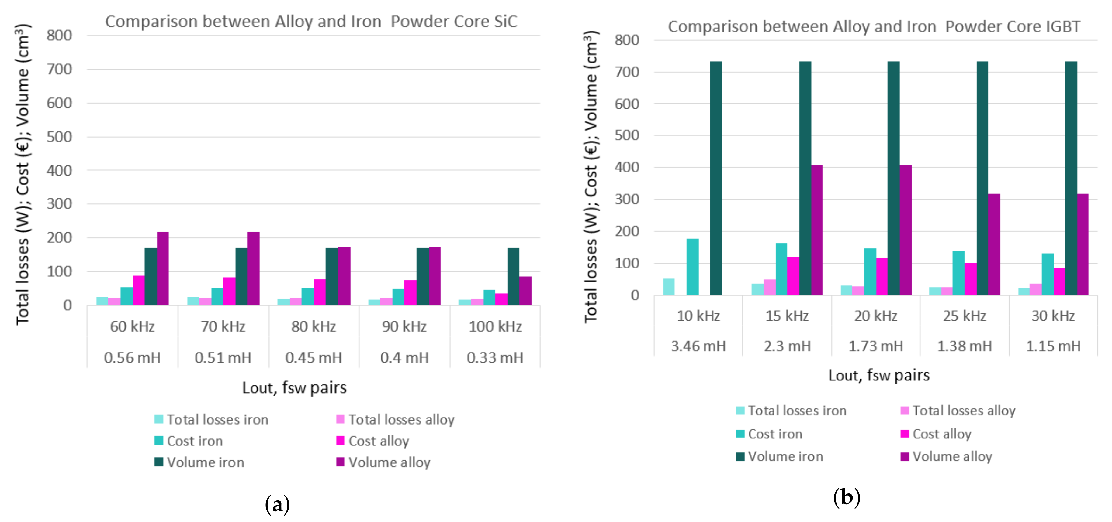
Figure 5, for the two core types found as the best compromise for the total inductor losses and inductor volume. Two different types have been considered for both converters, iron (in turquoise) and alloy (in pink) powder core from [31]. In Figure 5 is given the comparison of total core losses, costs (obtained from the core manufacturer) and volume for the case of 25 A inductor current corresponding to the 75 A output current. In the case of SiC-MOSFET the difference between the volume of iron and alloy inductors is not very marked, except in the case of the highest switching frequency (0.33 mH–100 kHz) where the alloy core allows one to have an inductor with volume reduced to half (171 cm 3 –85.5 cm 3 ).
For Si-IGBT-based converter there was more significant difference in the volume of iron and alloy core except for the 3.46 mH–10 kHz pair, where it was not possible to design the alloy powder core. When considering the lowest (10 kHz) and highest (30 kHz) switching frequencies, the alloy allowed 57% reduction in core volume.
Evident also are the reductions in volume, losses and costs in both iron and alloy powder core when comparing Figure 5a,b for SiC-MOSFET-based converter, confirming the advantages of using the SiC-MOSFET devices. For the two highest switching frequencies (30 kHz for Si-IGBT and 100 kHz for SiC-MOSFET), the SiC-MOSFET-based converter can offer the reduction of 73% of the core volume for alloy core, and 77% for the iron core, having around 60% lower cost.
In this case, the best compromise in terms of total losses and volume has been taken into account. The selected inductors are given in bold in Table 5. In some cases the best choice is iron core, while in other cases it is alloy core. For the SiC-MOSFET-based converter the best solutions are almost always in iron, except for the case with the highest switching frequency (100 kHz), which also represents a significant working condition, allowing one to make the most of the advantages offered by SiC-MOSFET devices and significantly reduce weight and volume. On the other hand, for Si-IGBT the best solutions are always in alloy, except for the lowest switching frequency (10 kHz) with only possible solution in iron. However, this working condition is not very significant because it leads to higher volume and cost. Further on in the analysis, only the inductors given in bold were considered for the efficiency comparisons.

5.2. Power Loss and Efficiency Comparisons

In this section the power loss and efficiency comparison is presented. The three-leg interleaved dc–dc converter supplying a resistive load and implemented in PLECS has been used for this purpose. For each specific value of L o u t the inductance with its winding resistance (as resulted from the inductor design shown in Table 6) has been used for the modeling. The converter losses have been determined directly from the PLECS simulation tool, while the inductor losses (for each specific inductor designed) have been calculated as described in Section 4.2.
In Figure 6 are given the dc–dc converter losses in the case of different output inductor–switching frequency pairs and output currents in the case of 50 ° C heat sink temperature. In particular, four values of the output current have been considered: 30, 45, 60 and 75 A. The two converters show rather similar losses, even though the SiC-MOSFET converter’s switching frequency is much higher than the one of Si-IGBT converter (60–100 kHz vs. 10–30 kHz). For the highest output current of 75 A, the SiC-MOSFET-based converter has 28%, 18% or 9% higher losses when compared to Si-IGBT-based converter for the switching frequencies below 80 kHz (for Si-IGBT below 20 kHz) respectively, but lower 1% for the 90kHz and 9% for 100 kHz, as shown in Figure 7a. Generally, all the losses show the same behavior, lower in case of Si-IGBT for the switching frequencies <20 kHz. More flat behavior of the losses for SiC-MOSFET-based converter can be noted, i.e., less variations with the change of L o u t f s w pairs for the specific current.
In Figure 8 are given the total inductor losses for the selected inductors from Section 5.1. In particular, they resulted from the sum of inductor core and winding losses in the case of different inductors and output currents, as for converter losses. Different inductors have been designed, as shown in Table 6. The criteria for the design were the lowest total inductor losses, but also the lowest volume. The standard design practice has been applied; for example, the difference of the unloaded and loaded unductor was set to 10%, the cross section of the winding was carefully selected taking into account the minimum banding radius of the wire, the filling of the core window area was set to less than 50%, etc.
From the Table 6 can be noted 3.7 times lower inductor volume when comparing the cases with highest switching frequencies in the case of SiC-MOSFET-based converter. In Figure 8 the maximum losses for SiC-MOSFET-based converter of 24.9 W can be seen for the 0.56 mH–60 kHz pair and 75 A output current, while for the Si-IGBT-based converter the maximum is for 3.46 mH–10 kHz pair reaching 52.6 W at 75 A output current. The minimum losses for SiC-MOSFET-based converter are for 0.4 mH–90 kHz with 6.9 W in the case of lowest output current, while for Si-IGBT-based converter the minimum losses of 10.7 W are for 1.38 mH–25 kHz pair and the same value of the output current. In Figure 7b are given the inductor losses for the highest output current, i.e., 75 A. The losses of SiC-MOSFET-based converter are lower for all L o u t f s w pairs, with the highest difference of 53% at the lowest switching frequency. Conveniently, the total one-leg losses are also depicted in Figure 7c, obtained as the sum of device losses and inductor losses per leg at 75 A output current. It is interesting to see that the Si-IGBT-based converter has higher losses in almost all cases, except the 1.73 mH–20 kHz case, where SiC-MOSFET-based converter shows 4% higher losses.
For the particular case in Figure 7c, where SiC-MOSFET-based converter shows slightly higher losses, the loss distribution has been analyzed for all the values of the output current. In Figure 9 is shown the distribution of the total losses (simulated device and analytical inductor) of one converter leg, and specifically for the 0.45 mH–80 kHz pair (SiC-MOSFET-based converter) and the 1.73 mH–20 kHz pair (Si-IGBT-based converter) in the case of 50 ° C heat sink temperature. The figure also gives the comparison with the theoretical values, calculated as explained in Section 4.1 and Section 4.2.
The total losses of SiC-MOSFET-based converter (dark pink) are higher only in the case of 75 A output current, as resulted also in Figure 7c, while for the other current values it shows lower losses compared to Si-IGBT converter (dark green). As for the losses of the devices in one converter leg, the switching losses which are also shown in the figure are slightly lower for the SiC-MOSFET-based converter, even though the switching frequency was four times higher. The total inductor loss (dotted traces) is slightly lower for SiC-MOSFET-based converter, having core losses invariant with the change of the output current, as expected. For the specific case of 75 A output current, the SiC-MOSFET-based converter shows elevated conduction losses, and this is the reason why it resulted in higher total losses. Moreover, also the good agreement between simulation results (first bar) and analytical results (second bar) for all cases can be observed.
In Figure 10 are shown the total three-leg losses of the two converters, including the inductor losses resulting from realistic simulations (for power switches), and analytical for the different inductors. Generally, the SiC-MOSFET-based converter showed lower total losses (in pink), especially for the lower output currents. The highest losses can be noted for the Si-IGBT-based converter and 1.15 mH–30 kHz pair for all the values of the output current, due to high devices’ losses. While the SiC-MOSFET-based converter has more uniform losses behavior with the change of switching frequency, this difference is more outlined in the Si-IGBT-based converter.
In Figure 11 are shown the efficiencies of the two three-leg converters for different L o u t f s w pairs and output currents. For both converters, the efficiency is rather high, higher in the case of lower switching frequencies due to lower losses. The SiC-MOSFET-based converter shows higher efficiency (ranging between 98.3% and 98.9%), while in the case of Si-IGBT the efficiency ranges from 98% to 99%. The efficiency curves are closer to each other in the SiC-MOSFET when compared to Si-IGBT case, meaning that in the SiC-MOSFET case there is a lower variability of efficiency with the change of L o u t f s w pairs. In the worst case (30 A) there is a variability of about 0.3% in the case of SiC-MOSFET and 0.7% in the case of Si-IGBT. Therefore it can be concluded that by adopting the SiC-MOSFET solution, efficiency depends less on the choice of switching frequency and inductor.

5.3. Heat Sink Volume

In order to conduct a throughout comparison of the two converters, the heat sink volume and cost should also be taken into account. The heat sink volume analysis was based on the power loss of the two converters at highest output current (75 A) and considering 50 ° C heat sink temperature. In order to evaluate the heat sink volume, it is necessary to calculate the thermal resistance of the heat sink:
r h = T h T a P t l o s s
where T h is the heat sink temperature, T a is the ambient temperature and P t l o s s is the total converter loss.
Once the r h is calculated, it is possible to obtain the heat sink volume based on natural air convection [33]. The minimum heat sink volume can be obtained from the fitting function:
V o l h e a t s i n k = 3263 e 13.09 r h + 1756 e 1.698 r h
where V o l h e a t s i n k is expressed in cm 3 and r h in Ω . Equation (17) in [33] has the results of the curve fitting of various extruded naturally cooled heat sinks against heat sink thermal resistance.
Heat sink volume calculated from the curve fitting function for the two converters is presented in Figure 12, starting from the lowest switching frequency considered for both converters. A room temperature of 25 ° C was selected as ambient temperature. The results show that the SiC-MOSFET-based converter has an increase of around 3% only in the case of 0.45 mH–80 kHz pair. In the other cases, the Si-IGBT-based converter has higher heat sink volume, with the highest difference of 7% in the case of highest switching frequency.

5.4. Cost Comparison

This section presents the cost comparison of the two interleaved dc–dc converters, taking into account only the costs that are different for the two converters, i.e., the switching device costs, the heat sink costs and the inductor costs. The same cost was considered for the other components (for example gate driver, power cables, etc.), and therefore was not included in this comparison.
In Figure 13 is shown the comparison of the converter efficiency (3-legs, including inductors), the total volume (heat sink and inductor, in dm 3 ) and total converter cost (in € per kW). For the efficiency comparison, the power switch losses were taken directly from the realistic circuit model implemented in PLECS, while for the different inductors they were calculated analytically. Note that the costs in Figure 13 refer to the sample prices of the main parts’ manufacturers in Europe. Having in mind that the price of SiC-MOSFET devices is 2–3 times the price of IGBT devices, and the costs of different inductors for the SiC-MOSFET-based converter generally being lower (due to lower volume), the goal of this analysis was to verify if the difference of the device cost can somehow be compensated with the lower inductor cost. Namely, Figure 13 confirms this fact, where the SiC-MOSFET-based converter shows lower total cost for all the L o u t f s w pairs. The trend of the cost curve for the SiC-MOSFET-based converter is almost flat, with the lowest cost for the highest switching frequency, i.e., 100 kHz. The Si-IGBT-based converter shows more cost variation, with the lowest cost for the highest switching frequency as well. For the higher switching frequencies, the two costs are practically the same for each device.
The total volume and efficiency confirm the advantage of using the SiC-MOSFET-based converter. The efficiency is almost always higher or equal to the one of the Si-IGBT-based converter. The only case in which the Si-IGBT-based converter showed higher efficiency was for 1.73 mH–20 kHz pair. The trend of the SiC-MOSFET efficiency curve is more flat, while the Si-IGBT-based converter shows higher variations with the lowest efficiency for 30 kHz switching frequency.
The real benefit can be seen in the total volume, where the lower volume can be noted for all the L o u t f s w pairs in the SiC-MOSFET-based converter. For the highest switching frequency, SiC-MOSFET-based converter offers the lowest total volume. Generally, Figure 13 leads to the conclusion that the best working conditions for Si-IGBT-based converter could be medium switching frequencies (20 kHz and 25 kHz), where the cost, volume and efficiency differences are less marked, while the worst working conditions are the lowest switching frequencies, with elevated cost and volume difference. On the other hand, the real advantage of the SiC-MOSFET-based converter can be seen at high switching frequencies, where the cost is practically the same for the two converters (and lowest for all cases), efficiency remains higher and total volume is lower.
These considerations, together with the fact that the prices for SiC-MOSFET devices tend to reduce greatly over ther years, indicate the convenience of using SiC-MOSFET devices, especially given the fact that it offers lower total volume.

6. Conclusions

An investigation of the three-phase interleaved dc–dc topology applied to the EV fast chargers was presented in this paper. This configuration permits the use of classic and reliable three-phase power switch devices, featuring high reliability and modularity, making it particularly interesting for EV fast charging.
Two technologies were considered for the efficiency comparison: dc–dc interleaved converters with SiC-MOSFET power devices and Si-IGBT power devices, on a wide range of switching frequencies and output inductances. The comparison was made by imposing the same requirements on the ripple of the output current (5%), in order to reduce the battery stress and extend its life.
The two converters were considered with the optimal switching parameters, based on the analysis done on detailed realistic parasitic circuit model and experimental measurement. The goal was to have the safe operation and minimum losses for both converters. The output inductor design follows the same criteria. For the simulation analysis, the spice models describing the realistic and dynamic behavior of the power switches and based on the experimental tests were utilized and verified both with LTspice and PLECS simulation packages.
The results show the convenience of using SiC-MOSFETs for the three-phase interleaved dc–dc topology on the wide range of L o u t f s w pairs. They also lead to the conclusion that the best working conditions for Si-IGBT-based converter could be medium switching frequencies (20 kHz and 25 kHz), where the cost, volume and efficiency differences are less marked, while the worst working condition is the lowest switching frequency, with elevated cost and volume difference. This is also the working condition where one could prefer the Si-IGBT solution due to its proven reliability and wide utilization by the industry. On the other hand, the real advantage of the SiC-MOSFET-based converter can be seen at high switching frequencies, where the cost is practically the same for the two converters, efficiency remains higher and total volume is lower.
Moreover, the analysis has shown that the higher price of SiC-MOSFET devices can be compensated for by the fact that the inductors utilized in the SiC-MOSFET-based converter have considerably lower costs due to the lower volume. In fact, the SiC-MOSFET-based converter showed lower costs for all L o u t f s w pairs. However, this is likely to be changed with greater reductions in the price of SiC-MOSFET devices in upcoming years, making in this way the cost difference more significant.

Author Contributions

J.L.: conceptualization, data curation, formal analysis, investigation, methodology, software and writing—original draft. V.G.M.: formal analysis, investigation and writing—review and editing. G.L.C.: formal analysis and writing—review and editing. F.C.: formal analysis, writing—review and editing and funding acquisition. All authors have read and agreed to the published version of the manuscript.

Funding

This research was supported by the project “FURTHER—Future Rivoluzionarie Tecnologie per velivoli più Elettrici” Code ARS01_01283, funded by the Italian Ministry of University and Research within Programma Operativo Nazionale (PON) “Ricerca e Innovazione” 2014–2020.

Conflicts of Interest

The authors declare no conflict of interest.

References

  1. Yilmaz, M.; Krein, P.T. Review of Battery Charger Topologies, Charging Power Levels, and Infrastructure for Plug-In Electric and Hybrid Vehicles. IEEE Trans. Power Electron. 2013, 28, 2151–2169. [Google Scholar] [CrossRef]
  2. Ghosh, A. Possibilities and Challenges for the Inclusion of the Electric Vehicle (EV) to Reduce the Carbon Footprint in the Transport Sector: A Review. Energies 2020, 13, 2602. [Google Scholar] [CrossRef]
  3. Tran, V.T.; Sutanto, D.; Muttaqi, K.M. The state of the art of battery charging infrastructure for electrical vehicles: Topologies, power control strategies, and future trend. In Proceedings of the 2017 Australasian Universities Power Engineering Conference (AUPEC), Melbourne, VIC, Australia, 19–22 November 2017; pp. 1–6. [Google Scholar]
  4. Monteiro, V.; Ferreira, J.C.; Nogueiras Meléndez, A.A.; Couto, C.; Afonso, J.L. Experimental Validation of a Novel Architecture Based on a Dual-Stage Converter for Off-Board Fast Battery Chargers of Electric Vehicles. IEEE Trans. Veh. Technol. 2018, 67, 1000–1011. [Google Scholar] [CrossRef] [Green Version]
  5. Musavi, F.; Eberle, W. Overview of wireless power transfer technologies for electric vehicle battery charging. IET Elect. Power Appl. 2014, 7, 60–66. [Google Scholar] [CrossRef]
  6. Celli, G.; Soma, G.G.; Pilo, F.; Lacu, F.; Mocci, S.; Natale, N. Aggregated electric vehicles load profiles with fast charging stations. In Proceedings of the 2014 Power Systems Computation Conference, Wroclaw, Poland, 18–22 August 2014; pp. 1–7. [Google Scholar]
  7. Barrero-González, F.; Milanés-Montero, M.I.; González-Romera, E.; Romero-Cadaval, E.; Roncero-Clemente, C. Control Strategy for Electric Vehicle Charging Station Power Converters with Active Functions. Energies 2019, 12, 3971. [Google Scholar] [CrossRef] [Green Version]
  8. Dusmez, S.; Cook, A.; Khaligh, A. Comprehensive analysis of high quality power converters for level 3 off-board chargers. In Proceedings of the 2011 IEEE Vehicle Power and Propulsion Conference, Chicago, IL, USA, 6–9 September 2011; pp. 1–10. [Google Scholar] [CrossRef]
  9. Channegowda, J.; Pathipati, V.K.; Williamson, S.S. Comprehensive review and comparison of DC fast charging converter topologies: Improving electric vehicle plug-to-wheels efficiency. In Proceedings of the 2015 IEEE 24th International Symposium on Industrial Electronics (ISIE), Buzios, Brazil, 3–5 June 2015; pp. 263–268. [Google Scholar]
  10. Rivera, S.; Wu, B.; Kouro, S.; Yaramasu, V.; Wang, J. Electric Vehicle Charging Station Using a Neutral Point Clamped Converter with Bipolar DC Bus. IEEE Trans. Ind. Electron. 2015, 62, 1999–2009. [Google Scholar] [CrossRef]
  11. Drobnic, K.; Grandi, G.; Hammami, M.; Mandrioli, R.; Ricco, M.; Viatkin, A.; Vujacic, M. An Output Ripple-Free Fast Charger for Electric Vehicles Based on Grid- Tied Modular Three-Phase Interleaved Converters. IEEE Trans. Ind. Appl. 2019, 55, 6102–6114. [Google Scholar] [CrossRef]
  12. Hammami, M.; Viatkin, A.; Ricco, M.; Grandi, G. A DC/DC Fast Charger for Electric Vehicles with Minimum Input/Output Ripple Based on Multiphase Interleaved Converters. In Proceedings of the IEEE ICCEP International Conference on Clean Electrical Power, 2–4 July 2019; pp. 187–192. [Google Scholar]
  13. Hwu, K.I.; Yau, Y.T. An Interleaved AC–DC Converter Based on Current Tracking. IEEE Trans. Ind. Electron. 2009, 56, 1456–1463. [Google Scholar] [CrossRef]
  14. Zhang, D.; Wang, F.; Burgos, R.; Lai, R.; Boroyevich, D. DC-link ripple current reduction for paralleled three-phase voltage-source converters with interleaving. IEEE Trans. Power Electron. 2011, 26, 1741–1753. [Google Scholar] [CrossRef]
  15. Huang, Y.; Tan, S.; Hui, S.Y. Multiphase-Interleaved High Step-Up DC/DC Resonant Converter for Wide Load Range. IEEE Trans. Power Electron. 2019, 34, 7703–7718. [Google Scholar] [CrossRef]
  16. Devaraj, E.; Joseph, P.K.; Karuppa Raj Rajagopal, T.; Sundaram, S. Renewable Energy Powered Plugged-In Hybrid Vehicle Charging System for Sustainable Transportation. Energies 2020, 13, 1944. [Google Scholar] [CrossRef] [Green Version]
  17. Tan, L.; Zhu, N.; Wu, B. An Integrated Inductor for Eliminating Circulating Current of Parallel Three-Level DC–DC Converter-Based EV Fast Charger. IEEE Trans. Ind. Electron. 2016, 63, 1362–1371. [Google Scholar] [CrossRef]
  18. Biela, J.; Schweizer, M.; Waffler, S.; Kolar, J.W. Evaluation of potentials for performance improvement of inverter and DC–DC converter systems by SiC power semiconductors. IEEE Trans. Ind. Electron. 2011, 58, 2872–2882. [Google Scholar] [CrossRef]
  19. Anthon, A.; Zhang, Z.; Andersen, M.A.E.; Holmes, D.G.; McGrath, B.; Teixeira, C.A. The Benefits of SiC mosfets in a T-Type Inverter for Grid-Tie Applications. IEEE Trans. Power Electron. 2017, 32, 2808–2821. [Google Scholar] [CrossRef] [Green Version]
  20. Zhang, D.; He, J.; Madhusoodhanan, S. Three-Level Two-Stage Decoupled Active NPC Converter with Si IGBT and SiC MOSFET. IEEE Trans. Ind. Appl. 2018, 54, 6169–6178. [Google Scholar] [CrossRef]
  21. Loncarski, J.; Monopoli, V.G.; Leuzzi, R.; Ristic, L.; Cupertino, F. Analytical and Simulation Fair Comparison of Three Level Si IGBT Based NPC Topologies and Two Level SiC MOSFET Based Topology for High Speed Drives. Energies 2019, 12, 4571. [Google Scholar] [CrossRef] [Green Version]
  22. Loncarski, J.; Ricco, M.; Monteiro, V.; Monopoli, V.G. Efficiency Comparison of a dc-dc Interleaved Converter Based on SiC-MOSFET and Si-IGBT Devices for EV Chargers. In Proceedings of the 14th International Conference on Compatibility, Power Electronics and Power Engineering (CPE-POWERENG), Setubal, Portugal, 8–10 July 2020; pp. 517–522. [Google Scholar]
  23. Stefanskyi, A.; Starzak, Ł.; Napieralski, A. Review of commercial SiC MOSFET models: Validity and accuracy. In Proceedings of the 24th International Conference Mixed Design of Integrated Circuits and Systems, Bydgoszcz, Poland, 22–24 June 2017; pp. 488–493. [Google Scholar]
  24. Rosa, E.B. The Self and Mutual Inductances of Linear Conductors. In Bulletin of the Bureau of Standards; Dept. of Commerce and Labor, Bureau of Standards, U.S. Govt. Print. Off.: Washington, DC, USA, 1908; pp. 301–344. [Google Scholar]
  25. SCT3080KLHR Product Information. Available online: https://www.rohm.com/products/sic-power-devices/sic-mosfet/sct3080klhr-product (accessed on 9 July 2020).
  26. SCS220KG Product Information. Available online: https://www.rohm.com/products/sic-power-devices/sic-schottky-barrier-diodes/scs220kg-product (accessed on 9 July 2020).
  27. RGS50TSX2DHR Product Information. Available online: https://www.rohm.com/products/igbt/field-stop-trench-igbt/rgs50tsx2dhr-product (accessed on 9 July 2020).
  28. Femia, N.; Petrone, G.; Spagnuolo, G.; Vitelli, M. Power Electronics and Control Techniques for Maximum Energy Harvesting in Photovoltaic Systems; CRC Press: Boca Raton, FL, USA, 2013. [Google Scholar]
  29. Semikron: Application Manual Power Semiconductors. Available online: https://www.semikron.com/service-support/downloads/ (accessed on 5 June 2020).
  30. Erickson, R.W.; Maksimovic, D. Fundamentals of Power Electronics, 2nd ed.; Springer: Berlin/Heidelberg, Germany, 2001. [Google Scholar]
  31. MicroMetals. Available online: Https://www.micrometals.com (accessed on 5 June 2020).
  32. Power Conversion and Line Filter Applications (Micro Metals Iron Powder Core Application Note, Issue L, Feb. 2007.). Available online: https://www.tme.eu/Document/82fc93ef93d05a020041f9203a13131a/MICROMETALS-Tseries.pdf (accessed on 9 July 2020).
  33. Gurpinar, E.; Castellazzi, A. Single-Phase T-Type Inverter Performance Benchmark Using Si IGBTs, SiC MOSFETs, and GaN HEMTs. IEEE Trans. Power Electron. 2016, 31, 7148–7160. [Google Scholar] [CrossRef]
Figure 1. Fast charger topology for EVs: (a) three-phase ac–dc converter and an interleaved dc–dc converter, and (b) control signals and typical output waveforms.
Energies 13 04585 g001
Figure 2. Dc–dc interleaved converter: full parasitic model of 3 legs.
Energies 13 04585 g002
Figure 3. Safe operating area: (a) SiC-MOSFET-based converter and (b) Si-IGBT-based converter.
Energies 13 04585 g003
Figure 4. Double pulse test: (a) schematic of the double pulse test and (b) an example of IGBT’s switching on losses for different temperatures.
Energies 13 04585 g004
Figure 5. Comparison of cost, volume and total calculated losses for iron and alloy powder cores: (a) SiC-MOSFET-based converter; (b) Si-IGBT-based converter.
Energies 13 04585 g005
Figure 6. Dc–dc converter losses per leg for different output inductors resulting from the simulation.
Energies 13 04585 g006
Figure 7. One-leg losses of SiC-MOSFET and Si-IGBT-based converters at 75 A output current: (a) simulated device losses, (b) analytical inductor losses, (c) total one-leg losses.
Energies 13 04585 g007
Figure 8. Total inductor analytical losses per leg.
Energies 13 04585 g008
Figure 9. Loss distribution for 0.45 mH–80 kHz and 1.73 mH–20 kHz pairs and comparison with analytical values.
Energies 13 04585 g009
Figure 10. Total 3-leg converter loss for SiC-MOSFET-based and Si-IGBT-based converters.
Energies 13 04585 g010
Figure 11. Efficiency comparison: (a) SiC-MOSFET-based converter and (b) Si-IGBT-based converter.
Energies 13 04585 g011
Figure 12. Comparison of the heat sink volume at 75 A output current and 50 ° C heat sink temperature for the two converters.
Energies 13 04585 g012
Figure 13. Efficiency, cost and total volume comparison of the two converters at 75 A output current and 50 ° C heat sink temperature.
Energies 13 04585 g013
Table 1. PCB parameters.
Parameter (Unit)Value
L c a b l e _ d c 1 ( μ H)1.77
R c a b l e _ d c 1 (m Ω )8.92
L c a b l e _ d c 2 ( μ H)1.74
R c a b l e _ d c 2 (m Ω )8.79
L p c b _ t r a c e _ d c l i n k (nH)36.5
L p c b _ t r a c e _ l e g (nH)66.5
L p c b _ t r a c e _ l e g / 2 (nH)33.25
L c a b _ l o a d ( μ H)0.834
R c a b _ l o a d (m Ω )4.21
Thin film capacitor C d c ( μ H)15
E S R (m Ω )4.8
E S L (nH)12.4
R d i s c h (k Ω )100
Table 2. Main device parameters.
ParametersRohm SiC MOSFET SCT3080KLHRSiC Schottky Diode SCS220KGRohm Si IGBT RGS50TSX2DHR
V d s 1200 V1200 V1200 V
I d s (25 ° C)31 A-50 A
I d s (100 ° C)22 A20 A/133 ° C25 A
R D S ( o n ) (25 ° C)80 m Ω N/AN/A
V C E s a t (25 ° C)N/AN/A1.7 V
Q g 60nC@18 VN/A67nC@15 V
V t h 2.7 VN/A6 V
V g s −4 to +22 VN/A±30 V
T j 175 ° C175 ° C175 ° C
P d i s s (25 ° C)165 W210 W395 W
r j c 0.7 ° C/W0.62 ° C/W0.38 ° C/W
Table 3. Main simulation parameters.
SiC-MOSFET-Based ConverterSi-IGBT-Based Converter
Inductance (mH)Switching Frequency (kHz) R g _ ext ( Ω )Inductance (mH)Switching Frequency (kHz) R g _ ext ( Ω )
0.566003.46103.5
0.517002.3153.5
0.458001.73203.5
0.49001.38253.5
0.3310001.15303.5
Table 4. Simulation parameters.
SiC-MOSFET Based ConverterSi-IGBT Based Converter
Parameter (unit)ValueParameter (unit)Value
V D C (V)800 V D C (V)800
R g _ e x t ( Ω )0 R g _ e x t ( Ω )3.5
R g _ i n t ( Ω )1.5 R g _ i n t ( Ω )1.5
D (%)50D (%)50
Table 5. Comparison of different core types.
L f sw PairsIron CoreAlloy Core
SiC-MOSFET-based converter
0.56 mH, 60 kHzT400-14D *OP-521014-2
0.51 mH, 70 kHzT400-14DOP-521014-2
0.45 mH, 80 kHzT400-14DOP-521014-2
0.4 mH, 90 kHzT400-14DOP-521014-2
0.33 mH, 100 kHzT400-14DSM-400026-2
Si-IGBT-based converter
3.46 mH, 10 kHzT650-14-
2.3 mH, 15 kHzT650-14FS-650014-2
1.73 mH, 20 kHzT650-14OD-650026-2
1.38 mH, 25 kHzT650-14OD-601026-2
1.15 mH, 30 kHzT650-14FS-601014-2
* In bold are given the inductors that later on are selected for further analysis.
Table 6. Inductor design.
SiC-MOSFET Based Converter
L o u t , f s w pairsCore typeNAWG R d c ( Ω ) A e (cm 2 ) m l t V e (cm 3 )
0.56 mH, 60 kHzT400-14D11070.030826.8514.62171
0.51 mH, 70 kHzT400-14D10570.028956.8514.46171
0.45 mH, 80 kHzT400-14D9870.026496.8514.24171
0.4 mH, 90 kHzT400-14D9260.020096.8514.76171
0.33 mH, 100 kHzSM-400026-28760.015223.522611.5185.5
Si-IGBT Based Converter
L o u t , f s w pairsCore typeNAWG R d c ( Ω ) A e (cm 2 ) m l t V e (cm 3 )
3.46 mH, 10 kHzT650-1421260.0750718.423.64734
2.3 mH, 15 kHzFS-650014-224160.065659.8718.09407
1.73 mH, 20 kHzOD-650026-215550.030499.8717.05407
1.38 mH, 25 kHzOD-601026-213750.02738.806417.19317
1.15 mH, 30 kHzFS-601014-216760.042668.806417.09317

