1. Introduction
In recent years, the use of power line communication (PLC) technology has become increasingly common. Although PLC technology was introduced many years ago, it is still being developed and successfully used in various areas, including both low and medium voltage scenarios. An example of this may be its wide use in advanced metering infrastructure (AMI) systems for various types of electrical measurements, as well as for remote control of electricity consumption by end-users [
1,
2,
3,
4,
5,
6]. This is primarily due to the possibility of utilizing an already existing infrastructure, including both low as well as high voltage power grids. As a result, the investment costs of the installation are significantly reduced and operator fees can be omitted. However, the disadvantages of PLC transmission include, most of all, the impact of environmental electromagnetic compatibility (EMC) disturbances, both conducted and induced, on the scope and quality of transmission [
7,
8,
9,
10,
11]. In addition, PLC transmission should not interfere with the basic functions of electricity networks, such as transmission and distribution of electricity itself. It should therefore adapt to the current technical conditions and operation restrictions of these networks.
The use of the broadband over power line (BPL) technology is obviously limited, due to possible interference with other systems. BPL solutions available on the market enable transmission only for strictly defined frequency bands. It should be also emphasized that different telecommunication operators, especially those related to wireless transmission systems (e.g., Wi-Fi and various terrestrial radio communication standards), are not particularly interested in the development of PLC technology.
Authors, familiar with the problem of maintaining communication in harsh environments, especially underground mines, have found that the use of BPL technology, particularly in MV cable networks, can be beneficial. BPL enables signal transmission within a frequency range of 2–30 MHz, with bitrates even up to 200 Mbps. This is much faster than narrowband communication. The BPL-PLC technology can be successfully used both for control and monitoring of environmental conditions, and secondary as voice and/or image transmission of the so-called last chance, especially during mine disaster or other random events [
9,
10,
11]. The underground cable lines are above all the most resistant to mechanical damage and thus can provide an effective transmission channel under various hazardous situations. Of course, in this case, battery-powered devices are mandatory.
However, to provide an effective BPL transmission in a particular network, it is necessary to examine and explain the impact of a number of factors, both external (harsh environment) and internal, related to the physical parameters of all network components (cables, permanent joints, connectors, bus bars, etc.), structure and network loading conditions (value and nature of distorted electrical quantities). It should be noted that the influence of the above-mentioned factors is variable over time and can be unpredictable [
12,
13,
14,
15].
The disadvantages of PLC transmission in low-voltage networks are recognized, widely analyzed, and well-known in literature [
7,
16]. In medium voltage networks, particularly in mines, the main problem in performing field tests is limited access, related to electrical safety. Therefore, it may be sometimes difficult to derive the physical quantities of the analyzed cable. Due to this, the verification of the propagation model becomes a major issue to overcome [
9,
10,
11]. Based on previous research conducted by the authors, it has been shown that the efficiency of high-frequency transmission in underground cable mine networks can be subjected to significant changes, depending on the network load conditions (with or without supply, under-voltage but unloaded, loaded, etc.), and this is not necessarily caused by noise, as the bridged effect of energy consumers can be neglected [
17,
18,
19].
It is particularly important to select effective ways of coupling modems with the cable line, taking into account the frequency of transmitted signals and the need to match to the characteristic impedance of the wired medium. However, one should be aware that the way of coupling modems with a power cable affects the signal path over the cable, and thus the quality of transmission. Therefore, when analyzing the effectiveness of the BPL-PLC technology, an appropriate contribution of the cable’s electrical parameters (resistance, capacity, inductance, conductivity) should be taken into account, depending on the type of coupling (the term coupling is used here to match or mismatch with a suitable coupler device [
16]). In practice, this task is not a simple matter. This applies especially to mixed-coupling, e.g., capacitive-inductive. Further improvements regarding coupling solutions are discussed in [
20].
The main purpose of carrying out research was the need to find redundant means of communication, compared to a traditional fiber optic or cooper media, which would prove to be not only stable but also resistant to mechanical damage, i.e., the impact of rock mass. During an emergency situation, medium voltage cables are hard to take damage. This makes them an ideal solution for maintaining a high-efficiency voice communication between miners and/or paramedic team during any rescue operation. It should be noted that the underground electrical network is different from the electrical networks used on the surface. The tested mining cable itself was reinforced with a galvanized steel tape and had a general screen.
The impact of the cable’s electrical parameters on the transmission quality for both inductive-inductive and capacitive-inductive types of coupling was analyzed and confirmed by field tests, which is a novelty. It should be emphasized that the mathematical models were appropriately adjusted by the authors (
Section 3). Additionally, the results of the research presented in
Section 4.1 were obtained using our custom-developed software. The results of theoretical research have been verified by tests under real-time operating conditions in a genuine mine, which is a significant added value. The transmission efficiency, regarding the amount of retransmitted data, depending on the TCP/IP window size, packet size, and the network latency for UDP, was also analyzed. Based on the obtained results, appropriate practical conclusions were made.
This work is an extended version and a direct continuation of our published conference paper [
21]. It summarizes many years of research conducted by the authors, hence some of the results were published early [
9,
10,
11,
21]. The content of
Section 3, as well as
Section 4.1 and
Section 4.3, has not been previously published. Results describing the quality evaluation of transmitted speech signal samples, including both couplings (inductive-inductive and capacitive-inductive), four speakers (two female and two male individuals), and transmission routes (A to B and vice versa) have been averaged overall, to present a comprehensive subjective analysis of the described communication system. The remaining sections, that is an introduction and description of BPL-PLC technology, have been extended and revised, respectively.
The manuscript consists of 5 sections.
Section 1 is an introduction to the discussed research subject along with the justification for the choice of this particular topic.
Section 2 presents a fragment of the medium voltage mining network, detailing the cable on which the tests were carried out, including the coupling method.
Section 3 analyzes the influence of individual electrical parameters of the cable and their change with frequency for five selected simulation models, regarding the length of the transmitted data packet, as well as a quality evaluation study of voice transmission. The results of analyzes and considerations along with the discussion are presented in
Section 4.
Section 5 summarizes and concludes this manuscript.
2. Materials and Methods
A part of the 6 kV mining network, selected for analysis and testing, along with indicated modem location, is shown in
Figure 1. This cable line was a part of an underground power grid with a total length of over 2.5 km, on which BPL-PLC implementation works were carried out. The analyzed mining cable was a YKGYFtznyn 6/3.6 kV 3 × 185 mm
2 type model, reinforced with a galvanized steel tape and a general screen. During the investigation, it was assumed that factors such as load or passives had no influence. Due to the type of utilized filters, the study was carried out in the 2–18 MHz frequency range. The utilized modems were bought freely on the market.
The cable under study, shown in
Figure 2, was a 3-phase mine cable (YKGYFtZnyn 3 × 185 mm
2) with an inner copper screen equipped with a steel armor to protect it. The L1, L2, and L3 phases separated uniformly from each other were made of stranded copper conductors with PVC insulation. The electrical parameters of the cable have been derived based on the knowledge concerning the cable’s structure, the cross-sectional geometrical dimensions, and properties of the used materials (conductive or insulating). The tested cable is specific due to its structure. It has been designed and made particularly for this kind of environment (mines). It differs from other common power cables intended for numerous applications, mainly it is a 3-phase model and has a steel armor. The solution of the cable earthing system and the associated signal flow are specific to mine applications.
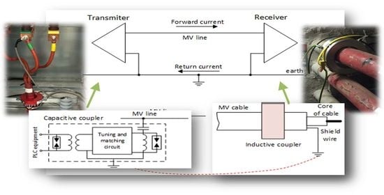
Theoretical considerations and field tests were carried out for both inductive-inductive and mixed capacitive-inductive couplings, as shown in
Figure 3. It should be emphasized that in mine electric networks the use of capacitive coupling is often troublesome, due to lack of access to phase conductors. This is particularly related to cables routed in shafts. In addition, capacitive type couplings are not recommended for use in medium voltage cable networks, due to electrical safety requirements in mines. In BPL-PLC solutions, such coupler should be connected directly to the phase/phases, without the use of any other short-circuit protection (fuse). This implies a high risk of both damage to equipment and electric shock to staff.
Therefore, the only way in such cases is to connect the capacitive coupler to the bus/phase, but through a thin enough electric wire of a sufficient length, to meet requirements of the electrical strength of the gap. Otherwise, the wire would simply evaporate under fault current. Additional information on BPL-PLC solutions, particularly related to smart grids, data transfer, as well as service quality estimation, may be found in [
22,
23,
24,
25].
3. Methodology
Simulation models described in this section consider the impact of wave propagation and packet length analysis in the wired medium, as well as a subjective quality evaluation study of real-time transmitted speech samples.
The objective parameter, based on which it was possible to practically verify the energy balance of the link, is the attenuation of the transmission medium. Therefore, to estimate the impact of the physical parameters of the cable with frequency, the authors developed the presented models and compared the obtained results with carried out measurements. It should be emphasized that only the model, considering the dependence of longitudinal resistance of the cable with frequency, is practically commonly used (approach no. 1). The basic model, known from the literature [
9], has been therefore appropriately modified to qualitatively and quantitatively assess the influence of selected physical parameters of the cable and their variation with frequency on the propagation conditions of the medium voltage 3-phase mining cable. Hence, the presented analysis of different 5 models (approaches).
Five theoretical models were used to consider the impact of the cable’s electrical parameters and frequency for the inductive-inductive and mixed capacitive-inductive coupling. In the first model (approach no. 1, propagation constant according to Equation (1)), only the variation of longitudinal cable resistance
R(
f) with respect to frequency was adopted for analysis. Other values of electrical quantities were calculated from equivalent circuits, taking into account the geometry of the utilized cable.
where:
L,
G,
C–transversal parameters of the cable.
To perform simulations for the second model (approach no. 2, propagation constant according to Equation (2)), the longitudinal cable conductance
G(
f) = 1/
R(
f) was assumed to be a function of frequency as well. Therefore, the propagation constant
γ could be derived from formula [
25]:
where:
µ–magnetic permeability for copper,
ε–dielectric constant for polyvinyl.
The third model (approach no. 3) takes into account the dependency of longitudinal resistance
R(
f) as well as transversal conductivity
G’(
f) of the cable with respect to frequency. The propagation constant
γ was therefore derived using the transmission line theory [
1,
9,
16]:
Taking the transverse conductivity value
G’ for polyvinyl, a large discrepancy with the results of attenuation measurements for the analyzed cable was observed. The highest compliance was found when assuming the value of this conductivity equal to the reciprocal of the longitudinal resistance of the cable, i.e.,
It should be noted that the convergence of the results increases with the length of the cable.
The fourth model (approach no. 4) assumed the dependency of
R,
G’ and
C on frequency. The propagation constant was calculated as
where:
C(
f) was determined analytically based on knowledge of all physical parameters and cable dimensions:
where:
ε,
σ–respective values for polyvinyl.
In the last model (approach no. 5), all electrical quantities of the cable were assumed to change with respect to frequency. The propagation constant was determined as for transmission line Equation (5). Whereas, the cable’s inductance
L(
f), including skin effect, was calculated from the formula:
where:
ε–value for polyvinyl, whereas
µ for copper, respectively.
The analysis of the efficiency of BPL-PLC transmission also required the respective selection of the IP protocol in the TCP version and connectionless UDP [
26,
27]. Therefore, we have measured and analyzed the influence of the amount of retransmissions, depending on the TCP window size, packet size, and network latency for UDP. Later on, a subjective study was carried out, considering speech samples sourced from ITU-T P.501 [
28]. This dataset included signal samples consisting of two sentences spoken by two female and two male individuals, in different languages. Due to the international character of the oil and mining industry, we have selected samples from 4 sets, namely: American English (AE), British English (EN), German (GE), and Polish (PL).
4. Results and Discussion
4.1. Wave Propagation
Selected results of analyzes and measurements are shown in
Figure 4. According to
Figure 4a, the variation of the calculated attenuation coefficient α versus cable length shows that the highest compliance with the measured data is obtained when using the theoretical approach in accordance with models 3–5 (approach no. 3–5) (the area between the red dotted lines represents the theoretical extent of regression error). The measurements were carried out under varying location of the output (inductive) coupler, in relation to the input coupler during different current load of the tested cable. The attenuation was measured using the dedicated software from the modem’s provider. As shown, the measurement point for 300 m differs significantly from the others, due to (most probably) the influence of the deformed wave of the load current of the tested cable. It should be noted that measurements were performed during one single day at a stable ambient temperature. However, the temperature of the cable could (of course) undergo some changes as a function of its current load. As a result, this could have some influence on the obtained result.
The calculations deviate the least from the regression curve in case of the considered inductive-inductive coupling. However, the simplest way to estimate the attenuation seems to be by means of model 5 (approach no. 5).
Knowing the structure and geometrical dimensions of the cable, equivalent values of resistance, conductivity, capacity, and inductance, were calculated, respectively. Next, the remaining data was derived using Equations (2)–(6). As for the characteristic impedance
Z0 of the cable, the results obtained using approach no. 2 differ from the others, as shown in
Figure 4b. The best approximation was also found for calculations based on model 5 (approach no. 5).
Approach no. 2 was adopted only due to the change of conductance of the cable. We have assumed that conductance was a function of frequency. We have also stated that if the conductance was calculated only from the geometric parameters of the cable (without the skin effect), the simulations differed significantly from the measurements. As shown in
Figure 4, the result corresponding to approach no. 2 was marked in yellow, whereas the blue color was related to model 1 (approach no. 1), which takes into account only the change in resistance as a function of frequency. The dependencies derived based on model 3 (approach no. 3), taking into account variation of both resistance and conductance with respect to frequency, were marked in red. The green color applied to model 4 (approach no. 4), which takes into account the dependence of capacity on frequency. Model 5 (approach no. 5) takes into account the change in all electrical parameters as a function of frequency.
It was found that the phase of the signal does not change with frequency and is close to zero, as can be seen from the curves shown in
Figure 4c. This only differs for calculations made in accordance with model 1 (approach no. 1). In this model, only the dependency of resistance on frequency was assumed.
According to calculations (based on model no. 5), the group delay tends to increase, as shown in
Figure 4d. This is in accordance with results regarding the impact of frame length on transmission efficiency. Therefore, it seems that the analysis of the effectiveness of BPL transmission in a medium voltage power cable, with the inductive-inductive coupling, according to model 5 (approach no. 5), gives the most reliable results.
The analysis of transmission efficiency in a medium voltage mine cable, with the mixed capacitive-inductive coupling, shown in
Figure 5, was performed using similar propagation modeling methods (approaches no. 1–5) as for the inductive-inductive ones. However, due to the specificity of this coupling, the contribution of resistance
R of only one phase was adopted for analysis (the model is calculated for a 3-phase cable system, but the capacitive coupler is connected to one phase).
The effect of the resistance of other cable elements, such as shielding (
Rs) and armor (
Ra), has been neglected. The assumption that
Rs and
Ra are omitted is related to the fact that signals were launched directly into the selected phase for capacitive coupling.
Figure 3c shows that the input capacitive coupler is connected to one phase, whereas the inductive coupler (installed anywhere) covers the entire cable. The closed path for transmitted signals is performed through the phase and the cable earthing system, as shown in
Figure 3b. This fact was of course taken into account when modeling the cable. As shown in
Figure 3c, there is not enough space inside the switchgear to install an inductive coupler (including, apart from the phase conductors, also the grounding conductor/screen). In this situation, it was necessary to use a capacitive coupler. This coupler must be connected directly to the selected phase without using any fuse. In the case of a short circuit of the coupler (capacitive divider), the entire switchgear would be simply damaged.
According to obtained results, it seems that method 5 (approach no. 5) is also the most convenient for analysis of the capacitive-inductive coupling, from a practical point of view. From the attenuation waveforms, as shown in
Figure 5a, and characteristic impedance, shown in
Figure 5b, a relationship can be deduced. In this case, one should emphasize that the attenuation increases as a function of cable length. However, the value of characteristic impedance does not increase and stabilizes at around 60 Ω. When it comes to group delay, as shown in
Figure 5c, method 5 (approach no. 5) also proved its superiority, compared to especially approach no. 1 and no. 3. However, these facts must be confirmed in detail by further examination, including a data packet length analysis.
4.2. Data Packet Length
The measurements for the TCP/IP protocol, depending on the length of the transmitted data packet, during a 10 min time interval, are shown in
Figure 6 and
Figure 7.
Based on carried out analyzes, it is clear that the smallest number of retransmissions occurs for small packet lengths. However, the use of small packets is closely related to the reduction of bandwidth at the TCP layer (measurements were taken without TCP window control). Obtained measurements show that reducing the length of a data packet significantly reduces the number of retransmissions in relation to the total number of transmissions, e.g., for 187 B, the number of retransmissions is equal to approx. 7%. However, for a packet of 1500 B, it increases to approx. 64%.
Subsequent measurements were therefore aimed at investigating the influence of the TCP window length on the packet retransmission effect. The results are shown in
Figure 8. According to the analysis, it can be unequivocally stated that retransmission of packets does not occur for fixed TCP window lengths. However, the performance characteristics of the network depend on the length of the packet, adjusted to the size of the TCP window.
Next, for the UDP protocol, network delay measurements were carried out, depending on the length of the packet. Obtained results of delay time in the PLC network, for the selected cable, are shown in
Figure 9.
Based on obtained results, one can clearly see that the latency in the network reduces significantly with the decrease of packet length. Next, a subjective quality evaluation study has been carried out, to validate the efficiency and usefulness of a BPL-PLC voice communication system.
4.3. Voice Transmission
The voice transmission efficiency was determined for a real-time operating BPL-PLC system. Its main aim was to investigate how do varying conditions, concerning different types of coupling (inductive-inductive and capacitive-inductive), transmission mode (mode 1—frequency range of 3–7.5 MHz and mode 11—frequency range of 2–7 MHz), as well as bitrate (8, 16, and 24 kbps), affect the end-user quality.
The tested speech samples were sourced from ITU-T P.501 [
28]. This dataset includes signal samples consisting of two sentences spoken by two female and two male individuals, in different languages. The length of each sample was equal to approx. 7 s. Taking into consideration the international character of the oil and mining industry, we have selected samples from 4 sets, namely: American English (AE), British English (EN), German (GE), and Polish (PL).
The original samples were available in the WAV 16-bit PCM format, with a sampling frequency set to 32 kHz. Whereas the degraded (transmitted) signal samples were coded at different bitrates, namely: 8, 16, and 24 kbps, using the Ogg Vorbis format, with sampling frequency changed to 44.1 kHz. We have decided to use this codec due to its openness and full compatibility with the Linux operating system, as our custom-designed communication network was running on Linux-powered devices. We intended to have as much control over the hardware and software layer as possible.
After being transmitted in real-time (from point A to B, and vice versa), all speech samples were recorded on each receiving side for further processing and evaluation purposes. Additional information on low bitrate audio coding may be found in [
29,
30,
31]. Whereas the matter of consumption of multimedia content among end-users is discussed in [
32].
The subjective user assessment was carried out using high-quality headphones in a 5-step mean opinion score (MOS) absolute category rating (ACR) scale, with no reference signal available, ranging from 1 (bad quality) to 5 (excellent quality). The study involved a group of 16 people, aged between 25–35 years old, which best match the profile of professionals from the oil and mining industry. Each participant assessed the quality individually, according to [
33], and took a training phase before starting the essential study. A single session took approximately 25 min, with a short break in the middle of the test.
The results of the subjective quality evaluation, with respect to spoken language, bitrate, as well as transmission mode, are shown in
Figure 10. Obtained grades have been averaged, considering: type of coupling (both inductive-inductive and capacitive-inductive), speaker (both female and male individuals), and transmission route (both A to B and B to A), respectively. It is worth mentioning, that previous studies had shown that BPL-PLC transmission itself is asymmetrical and its efficiency, resulting in available bitrate, is higher for mode 11 (up to 34 Mbps) compared to mode 1 (up to 20 Mbps).
When statistically processing obtained data of all recordings and tests made with different speakers (male and female), having chosen a 95% confidence interval, the dispersion (mean ratio) was less than 10%. For the sake of clarity, it was not marked in the diagrams. Furthermore, it should be noted that neither individual had hearing disorders, and was fluent in both English and German, whereas Polish was their mother tongue.
As shown, the lowest bitrate equal to 8 kbps proved to be insufficient when it comes to delivering easily understandable voice messages. The signal was distorted, noise, and crackling in the audio recording were clearly audible. On the other hand, the medium bitrate of 16 kbps was ranked evidently better. Nevertheless, despite the fact that all messages were understandable, they did not receive a good overall rating. In the case of the highest bitrate of 24 kbps, all voice messages, whether spoken by a male or female lector, were clear and easily understandable. Additional information concerning perceptual audio coding, psychoacoustics, as well as the impact of noise on hearing, may be found in [
34,
35,
36,
37].
When examining obtained results, one should take into account that any voice transmission system may be considered as high-quality whenever it receives a MOS score of above 4.0 (good quality). As shown, the threshold of 24 kbps may be viewed as a breakpoint, when a further increase in bitrate will not relate to further raise in perceived subjective quality. Additionally, this subjective study has also shown the superiority of transmission mode 11 over mode 1. In all cases, regardless of the bitrate or type of sample, speech signals were ranked evidently higher. This becomes an important factor, particularly when designing stable and reliable systems and services for the oil and mining industry.
5. Conclusions
The analysis, considering high-frequency signal propagation in the cable medium, had shown that the most useful method to provide quality parameters of BPL-PLC transmission, in hazardous areas with the use of the mining cable, is the method related with a variation of all electrical quantities of the cable with the signal frequency. The usefulness of coupling modems with the wired medium, both inductive-inductive and mixed capacitive-inductive, had been also confirmed. This fact is of great importance for applications, where there is no direct access to the phase, e.g., cables in a mine shaft. The positive impact of reducing the packet length, in the case of BPL-PLC transmission, was also demonstrated.
As shown, the BPL-PLC wired medium, thanks to its physical properties, can provide a reliable voice transmission system. Even in a narrowband scenario (bitrates lower than 1 Mbps), e.g., caused by bandwidth limitations and/or severe damage, etc., this technology ensures a stable and reliable connection. Whenever an emergency situation occurs, voice commands, i.e., from a supervisor or paramedic, can help during any rescue operation. Previous random events around the world have shown how important is to maintain contact and communication with cutout miners. Since voice can be transmitted effectively at 24 kbps, it may be assumed that a physical link with a speed of 1 Mbps possibly will be sufficient for this type of service. Therefore, such transmission parameters could theoretically correspond to a damaged cable. However, this particular case (a real damaged cable), has not yet been investigated by the authors. Whereas, an investigation focused on determining the impact of noise on the quality of voice transmission in a BPL-PLC communication system, may be found in [
38].
It should be noted that the results of this work are innovative and not known previously in the literature. The technical medium examination had shown that inductive-inductive coupling has a clear advantage over mixed capacitive-inductive coupling. Moreover, when examining results in the case of voice transmission, there are situations in which mode 11 proved to be superior. As shown, the BPL-PLC technology can provide stable and reliable voice transmission services at 24 kbps, regardless of the spoken language, or even type of coupling. The results of this study can aid both researchers and scientists during the design and maintenance phase of a wired BPL-PLC voice communication system. Future studies may include research on the impact of aging on the physical parameters of the cable materials, as well as real mechanical damage to its elements, on the efficiency of voice transmission via the BPL-PLC communication system.

 ,
, 


