Parametric Analysis of an Energy-Harvesting Device for a Riser Based on Vortex-Induced Vibrations


School of Naval Architecture & Ocean Engineering, Jiangsu University of Science and Technology, Zhenjiang 212003, China
*
Author to whom correspondence should be addressed.
Energies 2020, 13(2), 414; https://0-doi-org.brum.beds.ac.uk/10.3390/en13020414
Submission received: 5 December 2019
/
Revised: 6 January 2020
/
Accepted: 8 January 2020
/
Published: 15 January 2020
(This article belongs to the Special Issue Hydrokinetic Energy Conversion: Technology, Research, and Outlook)
Abstract
:An energy-harvesting device for a riser based on vortex-induced vibration is proposed to overcome the power supply problem for a marine deep-water riser-monitoring device. To estimate the upper limit of its energy-capture efficiency, as well as the weight and size of the device designed, a discrete model of the riser was configured. With the experimental settings of Stappenbelt and Blevins, vortex-induced vibrations of the discrete cylinder with two degrees of freedom were simulated, and the parameters affecting the energy-acquisition efficiency of the riser were analyzed. The analysis of the dimensionless amplitude ratio showed that this ratio for the system decreased with increasing mass ratio and damping ratio. An analysis showed that the influences of the damping ratio on the energy-capture efficiency were different under medium and low-mass-ratio conditions. A maximum value of 38.44% was achieved when the mass ratio was 2.36 and the damping ratio was 0.05.
1. Introduction
A marine riser is a long thin tubular structure connecting the water surface platform and the subsea wellhead. In ultra-deep water, marine risers often experience a broad range of motion under the action of adverse environmental forces such as vortex shedding, currents, and wave forces [1]. Vortex-induced vibration (VIV) caused by vortex shedding leads to an accumulation of riser fatigue damage. With increasing water depth, VIV becomes the main factor in marine riser failure [1,2].
To mitigate the VIV-induced damage in marine risers, many experts world-wide have in recent years studied methods for its suppression [3,4,5]. The common approach is via passive control, which means directly changing the surface shape of the structure or adding additional devices to weaken or reduce the negative effect of flow. There are two reasons for changing the structural form, one is to reduce the external excitation force of vibration, such as setting up a riser suspension device [6] or using a spiral riser [7] to quell conditions under which vortices occur, adding auxiliary members to change the downstream wake form [8,9], establishing a riser group either in parallel or in tandem for the wakes to interfere mutually [10]; the other is to reduce the effect of the same excitation force, for example, damping on the vibrating pipeline, and convert the kinetic energy of pipeline into heat for dissipation [11] so as to reduce the vibration of the pipeline.
At the same time, monitoring of a deep-water riser is important (i) to ensure the safe operation of risers and their auxiliary systems [12], (ii) to provide real-time information of riser configuration and fatigue damage, (iii) to assist in optimizing inspections, maintenance, and repair, and (iv) to guide the research on the complex movements of risers to analyze and improve the design [13]. Given the different types of risers, different field monitoring technologies have been developed [14]. At present, the monitoring of the structural parameters of a deep-sea riser mainly relies on self-contained data recordings, 3-axis accelerometers, 2-axis angular velocity sensors and other instruments [12,15]. Although at present, the power supply of a riser mainly relies on the stay wire, deep-water environments are not conducive for a stay-wire power supply interfere. Because of the variability of the power consumption of a data collector, such as the battery power supply, long-term self-contained data acquisition is unsustainable [16]. For example, the monitoring unit of silicon-controlled rectifiers collects power 900 s every 3 h, and the battery supplies power for 90 days [12]. In addition, with the goal to improve continually the reliability as well as other performance indicators of instruments and equipment, the development of marine environmental monitoring instruments and equipment will be from continuous on-site monitoring to long-term in situ monitoring and from manual control to intelligent automated development [17]. Therefore, if the power supply of the detection system can be guaranteed, this development will overcome not only the low working frequency of the low-power chip and accelerate data acquisition and storage to completion, but also facilitate the realization of autonomous data acquisition, tracking and control, fault repair, integration of monitoring data, and other functions.
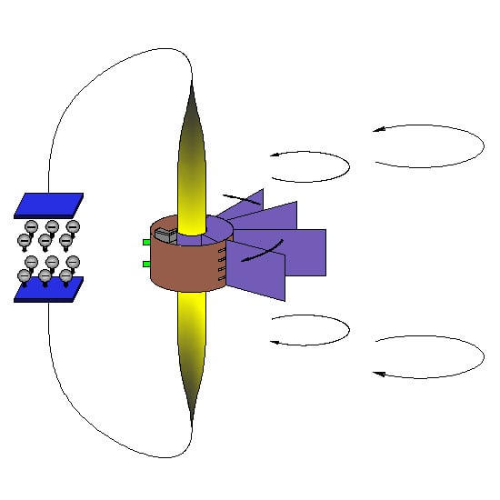
Since the time Bernitsas and Raghavan invented VIV aquatic clean energy, many experts have studied the power generation behind VIV [18,19]. With higher energy density, wider working velocity range, and higher flexibility [20,21,22] than underwater turbines, the VIV power generation device has become an option in supplying power to the riser-monitoring device. In addition, drawn from the vibration of the riser, the electric energy converted from the kinetic energy of the riser, and the generator plays a protective role in limiting the vibration of the riser. Xu Bai and collaborators [23] designed an energy-harvesting VIV monitoring device for a wing-pendulum-type marine riser that can vibrate under flow in any direction (Figure 1). By exploiting the VIV of the riser, the device not only generates power for monitoring the state of the riser but by harvesting the vibration energy captured by the structure from water flow, it also suppresses vibrations of the riser and reduces fatigue losses.
The conversion rate between the current energy and the vibration energy captured by the riser is an important index to evaluate the effect of power generation. To improve the conversion of the current design, it is necessary to analyze the state for which the power generation device obtains the best energy-capture efficiency. In Section 2 of this paper, the process of converting energy from the flow into electric energy is analyzed in simulations using a flexible slender riser configured from micro-segments with two degrees of freedom (2-DOF). In Section 3, the energy use efficiency of the riser is analyzed for which a 2-DOF coupled vibration model is proposed that considers the effect of flow direction. By analyzing the kinematic response of the two-dimensional cylinder, a semi-empirical expression for calculating the energy-capture efficiency of the 2-DOF cylinder is derived. Section 4 and Section 5 verify and assess the influence of mass ratio and damping ratio on the amplitude ratio and the energy-capture efficiency of the vibrator, as well as the response to changes in mass and damping ratios. Finally, Section 6 summarizes and draws conclusions.
2. Physics Model
Different damping forces of various magnitudes arise from the surface action of the riser and the wing-plate relative to sea water. Therefore, the vibrations of both riser and wing plate are not synchronous, and various angular differences lead to a relative movement between the coil fixed on the wing pendulum and the permanent magnet fixed on the shell, thereby generating a current with the cutting of magnetic inductance lines (Figure 2). The vibration of the wing depends on the vibration of the riser, and hence the fraction of the VIV of the riser available to obtain energy equals the upper limit of the energy captured by the power generation device. On the one hand, studying the power generation efficiency of the riser vibrator enables an upper limit of the energy-capture efficiency of the power generation device to be estimated; on the other hand, the weight and size specifications of the wing plate of the power generation device can be estimated by choosing both mass and damping ratios.
Under VIV conditions, the marine riser is not displaced length-ways along the pipe, but rather transversely. The displacement then creates a linear restoring force to a first approximation. With this assumption, the 2-DOF riser coupling model proposed in this paper simplifies. The vertical deformation of the riser in the unit is also ignored; the riser instead is to be regarded as a rigid cylinder. Because the fluid and structure are anisotropic of, the model has two independent dampers and stiffeners in the vertical plane along the pipe’s length (Figure 2).
Referring to, Compared with the spacing of the generator on the riser (Figure 2), its own radial dimension is smaller in order, and hence the influence of the wing-plate motion attitude on the riser VIV is ignored; it is only added to the vibration equation as an additional damping. Depending on the existing wake vortex form [24,25], the wake region from the VIV of the rigid cylinder after discretization is assumed to be two sets of point vortices of equal strength and opposite direction. The model diagram of the discrete vortices is given in Figure 3, the diameter of the discrete unit vibrator is 0.1 m, mass ratio , damping ratio .
3. Mathematical Model of the Power and Efficiency
The power generation efficiency of the vibrator reflects the use of the current energy by the energy capturing device. It is an important index in evaluating the feasibility of the riser for VIV power generation. The energy capturing efficiency per unit length from the generated motion induced by the flow is analyzed below.
As illustrated in Figure 4, the wake oscillator model assumes that the forces on the riser element are due to the discrete point vortices. According to the Biot–Savart law and Bernoulli’s equation, the periodically shed vortices induce a change in the fluid velocity field that then leads to changes in the pressure distribution on the cylinder surface, resulting from the combined external forces and under periodic change. The shedding of each vortex generates a periodic force on the riser in the X direction; a pair of vortices of equal opposite directions fall off to generate a periodic force on the riser in the Y direction. So the frequency of is twice that of .
Applying the circle theorem and the Blasius theorem, the vortex-induced hydrodynamic forces acting on a stationary cylinder are obtained.
where and are integral expressions of the pressure distribution p along the cylinder surface C, denotes the fluid density, is a complex potential, Γk denotes vortex strength of the k-th point vortex, (,) the components in Cartesian coordinates of the induced velocity of the remaining complex velocity potential after removing k-vortex elements, and (,) the components in Cartesian coordinates of the velocity of the mirror points of the k-th vortex element created by the induced velocity of the k-th vortex element. The first two terms on the right of the equation indicate the force on the cylinder arising from the change in the pressure field due to the motion of the point vortex. The latter term represents the force associated with a change in strength of the point vortex.
Combined with the flow-induced force and the complex potential of the discrete point vortex, ignoring higher-order terms, the simple harmonic function is used to describe the position of the vortex near the wall. Finally, the vortex-induced fluctuating hydrodynamic force of the structure is derived [26],
where denotes the vortex circle frequency of the purging vortex circle of the system, and the dimensionless empirical parameter.
Applying Newton’s law of motion with applied forces FVX and FVY produced by the wake vortex, the dynamic equation of the oscillator is
where denotes the coefficient of damping for the system, consisting of riser damping and the wing-plate fluid damping, ; and the displacements of oscillator, and are the first and second derivatives of respectively.
The Van der Pol equation is introduced to describe the dimensionless wake intensity of the VIV [27,28],
where H denotes an experimental parameter of the fluid, (, mass ratio) the coupling parameter of the Van der Pole Equation [26]. The relation holds for q(t) with dimensionless parameter representing the vortex strength.
The dynamic equation and the vortex strength equation are coupled simultaneously under a dimensionless transformation, yielding the coupled oscillator model:
where is a dimensionless time; and are dimensionless displacements, denotes the coefficient of damping ratio for the system, the fluid damping parameter, the dimensionless frequency ratio, and the mass parameters. The Strouhal number is set to = 0.19, the hydrodynamic parameter to h = 12, the average coefficient of drag = 0.2, and the average coefficient of lift = 0.3 [29].
From the literature [25], the expression for the motion of the cylinder is
in which A denotes the dimensionless maximum amplitude. Multiplying the vortex-induced hydrodynamic force and the velocity obtained from Equation (3), and integrating over a single period, the expression for the vibration energy per unit length of the cylinder per cycle is
In a uniform flow field, the work power of the fluid is , where gives the fluid pressure and the flow within the area of fluid action. For the cylinders undergoing vibration, with D the effective projected area in the flow process, the fluid energy of the uniform flow field per unit length over a single period is
The ratio of the structural energy to the flow field energy is the energy-capture efficiency of the cylinder from the flow field. By considering the 2-DOF vibration in both directions of flow and in the transverse direction, the energy-capture efficiency of the cylinder in a uniform incoming flow in dimensionless parameters, becomes
showing that the efficiency is related to the square of the Strouhal number, the damping ratio of the system, the mass ratio, the dimensionless amplitude of 2-DOF, and the reduced velocity. Where, denotes the added mass coefficients, the reduced velocity.
The Strouhal number is related to the velocity, the frequency of vortex shedding, and the cylinder diameter, whereas the reduced velocity is related to the structure frequency, the velocity, and the cylinder diameter. The damping ratio of the system changes with changes in mass and structural form, and the dimensionless amplitude changes with changes in other parameters. In total, the mass ratio and the system damping ratio are the parameters directly influencing the variation in energy-capture efficiency. The effective results may be obtained through their analysis and calculation.
4. Results and Discussions
4.1. Mass Ratio and Dimensionless Amplitude
As a fluid–solid coupling variable, the dimensionless amplitude cannot be obtained directly. Because the mass ratio for a marine environment is relatively low, the dimensionless amplitude of the riser’s vibrator under low-mass-ratio conditions is analyzed first. The experimental parameter settings of Stappenbelt and collaborators (Table 1) [30] were inputted into the 2-DOF calculation model for a comparison of calculated results with experimental results (Figure 5).
As shown in Figure 5, remove the effect of the hysteresis effect, the simulation and experimental amplitude ratio trend is consistent, taking the large vibration as an example, the maximum dimensionless amplitude error is 7.68%. The simulation is in good agreement with the corresponding experimental results. For transverse flow vibrations, as the mass ratio increases, the frequency lock of vibration is always within the range Ur = 4–8 although the peak value of the dimensionless amplitude decreases gradually. For a mass ratio of = 2.36, the peak value of the dimensionless amplitude is at a maximum value of 1.5, whereas for mass ratio = 8.79, it decreases to 0.6. In addition, hysteresis develops with increasing mass ratio. Hysteresis means that the change in dimensionless amplitude lags behind the change in velocity when the reduction velocity increases or decreases. The main reason for this significant hysteresis is that the fluid–solid coupling parameter changes exponentially with mass ratio that gives rise to obvious nonlinear characteristics.
For the downstream vibration, with increasing mass ratio, the peak value of its dimensionless amplitude decreases gradually. With a mass ratio of = 2.36, the peak value of the dimensionless amplitude is at its maximum value of 0.4 but decreases to 0.05 when the mass ratio is = 8.79. However, the position of the dimensionless amplitude peak in the downstream direction is independent of the mass ratio and is basically stable near .
The dimensionless amplitude is inversely related to the mass ratio for both the transverse and downstream flow-induced vibrations. When = 2.36, the transverse dimensionless amplitude of the vibration is much larger than that for the flow direction, but becomes larger than that of the transverse direction when = 8.79, indicating that the decreasing speed of the amplitude in the downstream direction is far less than that in the transverse direction. Moreover, the higher the mass ratio, the greater the influence of the vibration in the downstream direction on the whole. In addition, the lower the mass ratio, the wider is the range of the frequency lock of the vibration, i.e., the lower the mass ratio, the better the device is able to capture energy over the larger range in velocity.
4.2. System Damping Ratio and Dimensionless Amplitude
Besides the mass ratio, the damping ratio also affects the oscillation dimensionless amplitude and must be considered in the calculation of energy-capture efficiency of the vibrator. The first two groups of parameters in the low-mass-ratio experiment of the group in Michigan [20,30] were selected for verification, and the parameter settings were imported into the 2-DOF calculation model to calculate the dimensionless amplitude of the vibrator in the flow and transverse directions. Comparisons between calculation and experimental results were performed (Figure 6); a selection of calculation parameter settings is presented in Table 2.
As shown in Figure 6, remove the effect of the hysteresis effect, the simulation and experimental amplitude ratio trend is consistent, taking the large vibration as an example, the maximum dimensionless amplitude error is 17.07%. The simulation is in good agreement with the corresponding experimental results. For the transverse flow vibration, with increasing damping ratio, the frequency locking of the vibrator is always within the range Ur = 4–8, but the peak value of the dimensionless amplitude decreases gradually. When the damping ratio is = 0.002, the peak value of dimensionless amplitude is at 1.1, whereas it decreases to 0.7 when the damping ratio increase to = 0.02.
For the downstream vibration, with increasing damping ratio, the peak value of the dimensionless amplitude of the vibrator decreases gradually. When the mass damping ratio is = 0.002, the peak value of the dimensionless amplitude is at a maximum value of 0.08, and when the damping ratio = 0.02, it decreases to 0.1. In addition, the downstream vibration of the vibrator is concentrated in the reduced velocity range Ur = 4–8; downstream vibrations outside the range can be ignored.
In general, the dimensionless amplitude of the system is negatively correlated with the damping ratio for both transverse and downstream flow-induced vibrations. Under constant mass ratio conditions, a low damping ratio helps to increase the dimensionless amplitude peak and the range of frequency lock.
4.3. Comparative Analysis of Dimensionless Amplitude
According to the flow-induced vibration experiments of a single DOF cylinder and a 2-DOF cylinder performed by Williamson and collaborators [24,25] and Stappenbelt and collaborators. Ref. [30], the vibration amplitude along the flow direction cannot be ignored. From the vortex shedding law, the downstream vibration frequency of the vibrator is always twice the transverse frequency, so the contribution of the downstream vibration to the energy absorption of the structure cannot be ignored. To assess the influence of vibration in the downstream direction, the ratio of the dimensionless amplitude in the downstream direction to that in the transverse direction is introduced and referred to as the amplitude ratio. The rate of change for the amplitude ratio under different damping ratios and different mass ratio conditions were examined (Figure 7), the parameter settings used being the same as those in the experiment described in Ref. [30].
The amplitude ratio for various mass ratios and damping ratios increases gradually with increasing reduction speed, reaching a maximum value at , and then decreases. The amplitude ratio for damping ratios tends to stabilize. The downstream vibration accounts for a large fraction of the flow at low velocities and then decreases rapidly because the resonance resulting from the subsequent frequency lock causes the transverse vibration to increase rapidly.
In the peak range of reduced velocities , when the damping ratio is , the amplitude ratio of the riser vibration is positively correlated with the mass ratio; when the damping ratio is , the amplitude ratio is inversely correlated with the mass ratio, suggesting that the influence of the damping force on the downstream VIV is far greater than that for transverse flow vibrations. In addition, when the damping ratio is , the amplitude ratio is less than 1 at each value of the reduced velocity; that is, the transverse vibration is always dominant.
For a fixed mass ratio, the peak value of the amplitude ratio always decreases with increasing damping ratio, whereas with increasing rate of reduction, the value of the amplitude ratio after the final flattening is basically not affected by the damping ratio. For example, for = 2.36 at a high flow velocity, the amplitude ratio is always stable at about 0.4.
In the frequency lock regime, i.e., the best working range for the VIV power generation device, the vibration conditions for each mass ratio and damping ratio setting have the same characteristics; specifically, the amplitude ratio is less than 1, and the amplitude ratio decreases with increasing mass ratio. This shows that the vibration in the region of the vortex-induced resonance is mainly in the transverse direction, and the low mass ratio enhances the dimensionless amplitude in the downstream direction.
In brief, in an environment with low flow rates, a larger mass ratio may be considered when the damping ratio is to produce a larger amplitude; however, for high damping ratios, and for high flow rates, a low mass ratio achieves greater enhancements in power generation from the device when operating in the frequency lock regime.
5. Energy-Capture Efficiency of the Proposed Device
Based on calculations performed with rigid columns of various mass ratios and damping ratios, curves were obtained showing the dependence of the energy-capture efficiency for the riser vibrator undergoing 2-DOF vibrations under a reduced velocity (Figure 8).
In general, with increasing reduced velocity, the energy-capture efficiency increases first and then decreases, with the efficiency in the interval being larger. This is mainly because the vibration frequency of the riser’s vibrator is close to the vortex shedding frequency, promoting resonance, and locking the vortex shedding frequency onto the vibration frequency. For different mass ratios and damping ratios, when , the energy-capture efficiency reaches a maximum of 38.44%. At this instance, the mass ratio of the vibrator is and the damping ratio is = 0.05.
At a fixed damping ratio, the lower the mass ratio, the larger is the frequency lock range. For example, when the damping ratio is = 0.05, the frequency lock range is ; when the mass ratio rises to , this range reduces to . Therefore, the low-mass-ratio vibrator has a wider generating range and is suitable in relatively more complex sea conditions. In addition, a high mass ratio combined with a low damping ratio reduces the energy-capture efficiency slowly after exiting the frequency lock regime (Figure 9a). When the damping ratio equals 0.6, even if the frequency is outside the locking regime, the energy-capture efficiency is still 51% of the peak energy-capture efficiency.
For the same damping ratio, there is an inverse correlation between the energy-capture efficiency and the mass ratio, but the sensitivity of the efficiency on the mass ratio is different for different damping ratios. As in Equation (9), the energy-capture efficiency is directly affected by the dimensionless amplitude and damping ratio. Generally, an increase in the damping ratio will cause a decrease in the amplitude ratio, which will lead to a decrease in the peak energy-capture efficiency. However, if the damping ratio is very small, the increase in the dimensionless amplitude due to the reduction of the damping ratio is much smaller than the reduction of the damping ratio itself, so the peak energy-capture efficiency will decrease. In addition, under larger or smaller damping ratios, the sensitivity of energy-capture efficiency to mass ratio is not high. When = 0.05, reducing the mass ratio from 8.76 to 2.36 leads to a peak energy-harvesting efficiency improvement of 32.95%; when ξ = 0.006 and ξ = 0.6, the peak energy-harvesting efficiency is increased by 6.08% and 7.39%, respectively (Figure 9a). This is the result of the superposition of the decrease caused by the damping ratio and the increase caused by the decrease in mass ratio. Therefore, for an appropriate damping ratio, choosing a lower mass ratio may improve the riser power generation efficiency significantly.
However, the influence of damping ratio on energy-capture efficiency is relatively complex for a fixed mass ratio (Figure 9b). When the mass ratio is , the maximum energy-capture efficiency is inversely related to the damping ratio, whereas for , there is an optimal damping ratio that maximizes the energy-capture efficiency of the vibrator for a given mass ratio. Different mass ratios correspond to different optimal damping ratios. When the mass ratio is = 2.36, the damping ratio is = 0.05 and has the largest vibrator energy-capture efficiency, followed by = 0.1. However, when = 5.19, the efficiency at = 0.006 exceeds that at = 0.1; when = 8.76, the energy-capture efficiency is highest for = 0.006 (Figure 9a). This is because, at = 0.05, the rate of change for the maximum energy-capture efficiency as mass ratio decreases is far greater than that at ξ = 0.006.
Therefore, for a riser with a high mass ratio, a lower damping ratio is more conducive in improving the energy-capture efficiency of power generation. However, when the mass ratio is low, the maximum energy-capture efficiency rises first and then declines with increasing damping ratio, and hence an appropriate damping ratio needs to be found to obtain a higher energy-capture efficiency.
6. Conclusions
According to the analysis above, it is valuable to collect the vortex-induced vibration energy of the riser to supply the detection device. For riser with a mass ratio , a damping ratio , by changing the mass ratio and damping ratio parameter settings, the dimensionless transverse amplitude, dimensionless downstream amplitude and the trajectory of motion during flow-induced vibration in the cylinder were obtained, and the dimensionless amplitude ratio and energy-capture efficiency were analyzed. The following is a summary of results:
- With increasing mass ratio, the dimensionless amplitudes of the flow-induced vibration of the cylinder in both downstream and transverse directions decreased, and the range of “frequency lock” decreased; with increasing damping ratio, the dimensionless amplitudes of the flow direction in the cylinder and the transverse direction also decreased, but the range of “frequency lock” remained unchanged. The maximum value of the transverse amplitude occurred near the reduced velocity .
- Taking the damping ratio = 0.1 as a threshold, the low and high mass ratios of the cylinder at > 0.1 account for most of the amplitude along the flow direction. The influence of the vibration along the flow direction cannot be ignored.
- The maximum value of the energy-capture efficiency occurred near the reduced velocity . For each damping ratio and mass ratio setting, the maximum energy-capture efficiency was 38.44%. In this instance, the mass ratio of the vibrator was = 2.36 and the damping ratio = 0.05.
- Regardless of damping ratio, with increasing mass ratio, the energy-capture efficiency of the cylinder decreased; however, with the mass ratio of as a threshold, the maximum energy-capture efficiency of a high mass ratio vibrator was inversely related to the damping ratio, whereas the maximum energy-capture efficiency of a low-mass-ratio vibrator increased initially and then decreased with increasing damping ratio. The maximum value of the energy-capture efficiency occurred near the reduced velocity .
- Because the “frequency lock” regime expands with decreasing mass ratio, the low-mass-ratio vibrator may also operate over a larger velocity range. However, for extreme values of the damping ratio, the energy-capture efficiency of the low-mass-ratio vibrator remained to a certain extent, which can be used in high-velocity water flows.
Author Contributions
X.B. planned the whole idea. Y.C. designed the computing method. C.H. analyzed the experimental date and wrote the original manuscript. X.B. and C.H. and Y.C. revised the final manuscript. All authors have read and agreed to the published version of the manuscript.
Funding
This research received no external funding.
Acknowledgments
The authors are grateful to the National Natural Science Foundation of China (Grant No. 51879125), the Jiangsu Provincial Higher Education Natural Science Research Major Project (Grant No. 18KJA580003), and the Jiangsu Province “Six Talents Peak” High-level Talents Support Project (Grant No. 2018-KTHY-033).
Conflicts of Interest
The authors declare no conflict of interest.
Nomenclature
| Symbol | Meaning |
| , | vortex-induced hydrodynamic forces acting on a stationary cylinder |
| fluid density | |
| complex potential of fluid | |
| vortex strength of the k-th point vortex | |
| (,) | components in Cartesian coordinates of the induced velocity of the remaining complex velocity potential after removing k-vortex elements |
| (,) | components in Cartesian coordinates of the velocity of the mirror points of the k-th vortex element created by the induced velocity of the k-th vortex element |
| vortex circle frequency | |
| dimensionless empirical parameter | |
| coefficient of damping for the system, consisting of riser damping and the wing-plate fluid damping, | |
| , | displacements of oscillator |
| ,(,) | the first and second derivatives of () respectively |
| H | an experimental parameter of the fluid |
| mass ratio | |
| coupling parameter of the Van der Pole equation | |
| dimensionless parameter of the vortex strength | |
| dimensionless time | |
| ; | dimensionless displacements ; |
| coefficient of damping ratio for the system | |
| fluid damping parameter | |
| fluid damping parameter | |
| mass parameters | |
| Strouhal number = 0.19 | |
| h | hydrodynamic parameter h = 12 |
| CD0 | average coefficient of drag CD0 = 0.2 |
| CL0 | average coefficient of lift CL0 = 0.3 |
| vortex period | |
| fluid pressure | |
| flow within the area of fluid action | |
| the fluid energy of the uniform flow field per unit length over a single period | |
| the added mass coefficients | |
| the reduced velocity | |
| energy-capture efficiency | |
| peak energy-capture efficiency |
References
- Cerkovnik, M.; Chang, S.; Griffin, C. Fatigue analysis of tether chain in hybrid risers. In Proceedings of the Asme International Conference on Ocean, Offshore and Arctic Engineering, American Society of Mechanical Engineers, Rio de Janeiro, Brazil, 1–6 July 2012. [Google Scholar]
- Li, B.; Wang, H.; Shen, X.; Yan, Y.; Yang, F.; Hua, F. Deep-water riser fatigue monitoring systems based on acoustic telemetry. J. Ocean Univ. China 2014, 13, 951–956. [Google Scholar] [CrossRef]
- Wang, K.; Ji, C.; Chi, Q.; Wu, H. Hydrodynamic force investigation of a rigid cylinder under the coupling CF and IL motion. J. Fluid. Struct. 2018, 81, 598–616. [Google Scholar] [CrossRef]
- Chen, L.F.; Wu, G.X. Boundary shear flow past a cylinder near a wall. Appl. Ocean Res. 2019, 92. [Google Scholar] [CrossRef]
- Williamson, C.H.K.; Govardhan, R. Vortex-induced vibrations. Annu. Rev. Fluid Mech. 2004, 36, 413–455. [Google Scholar] [CrossRef] [Green Version]
- Lei, G.; Menglan, D.; Xinhu, Z.; Yu, Z.; Ke, T.; Lei, Y. Effect analysis of vibration reduction and fatigue suppression of new deep-water riser suspension device. Oil Field Equip. 2014, 43, 1–6. [Google Scholar]
- Yunlong, L.; Jijun, G. Study on a new type of suppression device for vortex induced vibration of marine riser. Pipeline Technol. Equip. 2019, 4, 13–17, 43. [Google Scholar]
- Song, Z.; Duan, M.; Gu, J. Numerical investigation on the suppression of VIV for a circular cylinder by three small control rods. Appl. Ocean Res. 2017, 64, 169–183. [Google Scholar] [CrossRef]
- Zhu, H.; Yao, J. Numerical evaluation of passive control of VIV by small control rods. Appl. Ocean Res. 2015, 51, 93–116. [Google Scholar] [CrossRef]
- Huera-Huarte, F.J.; Bearman, P.W. Vortex and wake-induced vibrations of a tandem arrangement of two flexible circular cylinders with near wake interference. J. Fluid. Struct. 2011, 27, 193–211. [Google Scholar] [CrossRef]
- Dongdong, Y.; Lidong, H.; Peiyao, J. Research on the application of damping technology in pipeline. Noise Vib. Control 2017, 37, 186–189. [Google Scholar]
- Zhihui, H. Research progress of deep-water riser monitoring technology. In Proceedings of the 15th China Ocean (Shore) Engineering Symposium, China Ocean Engineering Society: Ocean Engineering Branch of China Ocean society, Taiyuan, China, 7–11 August 2011; pp. 94–99. [Google Scholar]
- Wei, D.; Yong, B. Development of deepwater riser monitoring systems. In Proceedings of the Third International Conference on Measuring Technology & Mechatronics Automation, IEEE Computer Society, Shangshai, China, 6–7 January 2011. [Google Scholar]
- Feng, Z. Research on Field Monitoring System and Monitoring Technology of Deep-Water Structure. Master’s Thesis, Dalian University of Technology, Dalian, China, 2009. [Google Scholar]
- Peng, R.; Yu, S.; Xuan, L.; Zhi, Z. Distributed optical fiber sensing technology for attitude monitoring of deep-sea riser. China Offshore Platf. 2014, 29, 26–32. [Google Scholar]
- Zhongmin, S.; Yan, Q.; Jiayue, L.; Da, T.; Jiandong, S.; Qianjin, Y.; Wenhua, W. A Deep-Sea Self-Contained Acceleration Sensor Data Acquisition Device. cn102062785a, 18 May 2011. [Google Scholar]
- Suiping, Q.; Yunzhou, L. Development status and trend of marine environmental monitoring technology and instruments and equipment. Shandong Sci. 2019, 5, 21–30. [Google Scholar]
- Qin, W.; Bai, X.; Bai, Y. Analysis and prediction for structural responses and hydrodynamic properties of two-degree-of-freedom vortex induced vibration. Mech. Adv. Mater. Struct. 2019, 1–11. [Google Scholar] [CrossRef]
- Bai, X.; Le, Z.; Qin, W. Effect of traveling waves on a long slender cylinder in vortex-induced vibration with two degrees of freedom. Comput. Fluid. 2019, 193, 104270. [Google Scholar] [CrossRef]
- Bernitsas, M.M.; Ben-Simon, Y.; Raghavan, K.; Garcia, E.M.H. The VIVACE converter: Model tests at high damping and Reynolds number around 105. J. Offshore Mech. Arct. Eng. 2009, 131, 011102. [Google Scholar] [CrossRef]
- Brika, D.; Laneville, A. Vortex-induced vibrations of a long flexible circular cylinder. J. Fluid Mech. 1993, 250, 481–508. [Google Scholar] [CrossRef]
- Jijian, L.; Xiang, Y.; Fang, L. Research status and prospect of fluid induced vibration energy utilization. South North Water Transf. Water Sci. Technol. 2018, 16, 176–188. [Google Scholar]
- Xu, B.; Zhi-Bin, L.; Wei, Q.; Xiaofang, L. Vortex Induced Vibration Self-Generation Monitoring Device for wing Pendulum Marine Riser. cn104811009a, 29 July 2015. [Google Scholar]
- Govardhan, R.; Williamson, C.H.K. Defining the ‘modified Griffin plot’ in vortex-induced vibration: Revealing the effect of Reynolds number using controlled damping. J. Fluid Mech. 2006, 561, 147–180. [Google Scholar] [CrossRef]
- Jauvtis, N.; Williamson, C.H.K. The effect of two degrees of freedom on vortex-induced vibration at low mass and damping. J. Fluid Mech. 2004, 509, 23–62. [Google Scholar] [CrossRef]
- Zhi-Bin, L.; Xu, B.; Qin, W. Study on marine rises vortex-induced vibration of two DOF on plane. In Proceedings of the Ships and Marine Structure Academic Meeting, Changsha, China, 3 September 2015; pp. 339–346. [Google Scholar]
- Bai, X.; Qin, W. Using vortex strength wake oscillator in modelling of vortex induced vibrations in two degrees of freedom. Eur. J. Mech. B Fluid. 2014, 48, 165–173. [Google Scholar] [CrossRef]
- Facchinetti, M.L.; Langre, E.D.; Biolley, F. Coupling of structure and wake oscillators in vortex-induced vibrations. J. Fluid. Struct. 2004, 19, 123–140. [Google Scholar] [CrossRef]
- Bernitsas, M.M.; Raghavan, K.; Ben-Simon, Y.; Garcia, E.M.H. VIVACE (vortex induced vibration aquatic clean energy): A new concept in generation of clean and renewable energy from fluid flow. J. Offshore Mech. Arct. Eng. 2008, 130, 1–15. [Google Scholar] [CrossRef]
- Stappenbelt, B.; Lalji, F.; Tan, G. Low mass ratio vortex-induced motion. In Proceedings of the 16th Australasian Fluid Mechanics Conference, 16AFMC, University of Queensland, Gold Coast, QLD, Australia, 3–7 December 2007. [Google Scholar]
Figure 1.
Wing pendulum marine riser VIV self-generating monitoring device [23].
Figure 1.
Wing pendulum marine riser VIV self-generating monitoring device [23].

Figure 2.
Discrete-element diagram of the vortex-induced vibration components of risers.

Figure 3.
Model of cylinder flow-induced vibration and discrete vortices.

Figure 4.
Parametric model of the spatial arrangement of vortices.

Figure 5.
Comparison of model test and calculated amplitude response for different mass ratios. (a) Transverse flow amplitude response; (b) Flow amplitude response.
Figure 5.
Comparison of model test and calculated amplitude response for different mass ratios. (a) Transverse flow amplitude response; (b) Flow amplitude response.

Figure 6.
Comparison of model test and calculated amplitude response for different damping ratios. (a) Transverse flow amplitude response; (b) Flow amplitude response.
Figure 6.
Comparison of model test and calculated amplitude response for different damping ratios. (a) Transverse flow amplitude response; (b) Flow amplitude response.

Figure 7.
Variation of amplitude ratio with reduced velocity for various mass ratios and damping ratios.
Figure 7.
Variation of amplitude ratio with reduced velocity for various mass ratios and damping ratios.


Figure 8.
Variation of energy conversion efficiency with reduce velocity in different mass ratio and damping ratio.
Figure 8.
Variation of energy conversion efficiency with reduce velocity in different mass ratio and damping ratio.


Figure 9.
Dependence of the peak energy-capture efficiency : (a) on mass ratio and (b) damping ratio .
Figure 9.
Dependence of the peak energy-capture efficiency : (a) on mass ratio and (b) damping ratio .


Table 1.
Input data from the test described in Ref. [30].
Table 1.
Input data from the test described in Ref. [30].
| m* | ξ | m*ξ |
|---|---|---|
| 2.36 | 0.006 | 0.0142 |
| 3.68 | 0.006 | 0.0221 |
| 6.54 | 0.006 | 0.0392 |
| 10.63 | 0.006 | 0.0638 |
Table 2.
Input data from the test described in Ref. [20].
Table 2.
Input data from the test described in Ref. [20].
| m* | ξ | m*ξ |
|---|---|---|
| 5.4 | 0.002 | 0.0108 |
| 5.4 | 0.02 | 0.108 |
© 2020 by the authors. Licensee MDPI, Basel, Switzerland. This article is an open access article distributed under the terms and conditions of the Creative Commons Attribution (CC BY) license (http://creativecommons.org/licenses/by/4.0/).
Share and Cite
MDPI and ACS Style
Bai, X.; Han, C.; Cheng, Y. Parametric Analysis of an Energy-Harvesting Device for a Riser Based on Vortex-Induced Vibrations. Energies 2020, 13, 414. https://0-doi-org.brum.beds.ac.uk/10.3390/en13020414
AMA Style
Bai X, Han C, Cheng Y. Parametric Analysis of an Energy-Harvesting Device for a Riser Based on Vortex-Induced Vibrations. Energies. 2020; 13(2):414. https://0-doi-org.brum.beds.ac.uk/10.3390/en13020414
Chicago/Turabian StyleBai, Xu, Chuanyu Han, and Yong Cheng. 2020. "Parametric Analysis of an Energy-Harvesting Device for a Riser Based on Vortex-Induced Vibrations" Energies 13, no. 2: 414. https://0-doi-org.brum.beds.ac.uk/10.3390/en13020414
Note that from the first issue of 2016, this journal uses article numbers instead of page numbers. See further details here.