Mathematical Model of Carbon Dioxide Injection into a Porous Reservoir Saturated with Methane and Its Gas Hydrate


1
Department of Applied Informatics and Programming, Sterlitamak Branch of Bashkir State University, 453100 Sterlitamak, Russia
2
Mavlutov Institute of Mechanics of UFRC RAS, 450054 Ufa, Russia
3
Tyumen Branch of Khristianovich Institute of Theoretical and Applied Mechanics SB RAS, 625026 Tyumen, Russia
4
Department of Development and Exploitation of Oil and Gas Fields, Industrial University of Tyumen, 625000 Tyumen, Russia
*
Author to whom correspondence should be addressed.
Energies 2020, 13(2), 440; https://0-doi-org.brum.beds.ac.uk/10.3390/en13020440
Submission received: 11 December 2019
/
Revised: 10 January 2020
/
Accepted: 14 January 2020
/
Published: 16 January 2020
Abstract
:In this paper, the process of methane replacement in gas hydrate with carbon dioxide during CO2 injection into a porous medium is studied. A model that takes into account both the heat and mass transfer in a porous medium and the diffusion kinetics of the replacement process is constructed. The influences of the diffusion coefficient, the permeability and extent of a reservoir on the time of full gas replacement in the hydrate are analyzed. It was established that at high values of the diffusion coefficient in hydrate, low values of the reservoir permeability, and with the growth of the reservoir length, the process of the CH4-CO2 replacement in CH4 hydrate will take place in the frontal regime and be limited, generally, by the filtration mass transfer. Otherwise, the replacement will limited by the diffusion of gas in the hydrate.
1. Introduction
Recently, special attention has been paid to the problem of developing natural gas hydrate deposits due to their wide spread in nature and the large reserves of hydrocarbons contained in such deposits. There are several main methods of methane recovery from a methane hydrate deposit: lowering the pressure and increasing the temperature of the deposit to the point of the hydrate decomposition, and injecting organic or brine solutions that promote the gas hydrate dissociation [1,2,3,4]. The mathematical modeling of the development of gas hydrate deposits using these methods is considered in [5,6,7,8,9,10,11]. The reduction of atmospheric emissions of carbon dioxide is very important in reducing the anthropogenic impact on climate. One way to solve this problem is the capture of industrial carbon dioxide gas and its further injection into geological formations for long-term storage. Mathematical models of the processes of heat and mass transfer in extended porous reservoirs upon carbon dioxide injection have been formulated; in particular, in [12,13,14].
One of the important environmental problems that needs to be addressed is the reduction of carbon dioxide emissions into the atmosphere. One of the methods of CO2 utilization is its underground conservation in the gas hydrate state [15]. The numerical study of the processes of heat and mass transfer, accompanied by hydrate formation, when injecting gas into a porous reservoir, is carried out, for example, in [16,17,18,19].
The above problems can be resolved in one way: by injecting carbon dioxide into the methane hydrate reservoir, followed by the exchange of methane with CO2 in the gas hydrate. This method allows the simultaneous conservation of CO2 and production of CH4 [20,21,22]. As a result of the above process, methane hydrate is replaced by CO2 hydrate without the release of free water, which contributes to maintaining the mechanical strength of the rock [23]. Also, in contrast to the decomposition of the gas hydrate under depression or heating to gas and water, in this case the process will be realized with little heat release [24].
Ohgaki K., Takano K. et al. [25] were one the first teams to investigate the recovery of CH4 with CO2 in the gas hydrate. In their work, the process of hydrate formation in water saturated with methane was experimentally studied when CO2 was injected into the solution. It was found that the stability region of CO2 hydrate is wider and the heat of hydrate formation is higher than that of methane hydrate. Also, during the experiments, it was revealed that, at the end of the process, the concentration of carbon dioxide hydrate was significantly higher than that of methane hydrate. The work from M. Ota [26] experimentally studied the process of the substitution of CH4 molecules by CO2 molecules in hydrate using laser spectroscopy methods. The influence of pressure and fugacity on the process was analyzed. Falenty A., Salamatin A.N., Kuhs W.F. et al. have experimentally investigated the process of replacing CH4 molecules by CO2 molecules in methane hydrate, obtained from ice powder [25,27]. It was established that, at the initial stage, a more intensive formation of CO2 hydrate occurs; then, the process slows down due to the formation of a CO2 hydrate film, which prevents the contact of carbon dioxide and methane hydrate, and the process is further determined by the diffusion mechanism.
The results of studies [25,26,27,28] successfully describe the features of the process kinetics but do not take into account the effect of heat and mass transfer in extended natural reservoirs. In addition, in [25,26,27,28] and other similar experimental studies, the results of studies of the replacement process in samples containing only the gas hydrate phase are described. However, a study of this process in porous media is also of great interest, since the high specific contact surfaces of gas, liquid and hydrate are realized in such media, which are necessary for the intensification of the replacement process. In addition, most natural gas hydrates are contained in porous media.
In the work of G. Tegze et al. [29], a theoretical description of the replacement process of methane by liquid carbon dioxide in gas hydrate in the porous medium sample is presented. The kinetics of the process are described using the phase-field model and the diffusion model. The results of the numerical simulation and experimental data are compared. It is worth noting that the mathematical model in [29] and other similar theoretical studies take into account only the kinetics of the process, but not the filtration and heat transfer in a reservoir. However, in the development of real extended gas hydrate reservoirs, filtration and heat transfer in the reservoir have a significant effect on the process features.
At present, there are only a few works on the mathematical modeling of the methane replacement processes with carbon dioxide taking into account heat and mass transfer in the reservoir. Thus, the mathematical models of the replacement of CH4 by CO2 when carbon dioxide is injected into the gas hydrate reservoir are presented in [30,31]. However, these studies do not take into account the diffusion kinetics of the substitution process.
Theoretical studies of the replacement process when injecting CO2 into a reservoir saturated with CH4 hydrate were carried out by White M.D., McGrail B.P. et al. [32,33,34]. In these works, a mathematical model is presented, used simulators are described, and numerical solutions are obtained for the process of methane extraction from the reservoir saturated with hydrate when carbon dioxide is injected in different phase states. In these works, mathematical models take into account both the kinetics of the replacement process and the heat and mass transfer in the reservoir. The description of the kinetics is based on the Kim–Bishna model [35,36]. This model assumes that the rate of the replacement process is related with the diffusion mass transfer of carbon dioxide and methane in a gas hydrate. The rate of hydrate formation directly depends on the difference between the pressure in gas phase and the equilibrium pressure of hydrate formation. The proportionality coefficient, called the kinetic parameter, is independent of time. Therefore, the model of Kim–Bishna does not take into account the deceleration of the driving force of the substitution process with the increasing thickness of the carbon dioxide layer over time.
In this paper, we present a mathematical model for the exchange of CH4 with CO2 in gas hydrate, taking into account both the kinetics and heat and mass transfer in a natural reservoir. At the same time, when describing the kinetics of the replacement process, the dependence of the rate of diffusion mass transfer of carbon dioxide in the gas hydrate on the growth of the thickness of the carbon dioxide gas monohydrate layer is taken into account. Mainly, attention is paid to the study of the degree of influence of the replacement kinetics and heat and mass transfer in the reservoir on the intensity of the methane recovery process from the gas hydrate at different parameters of the reservoir.
2. Mathematical Model
2.1. Problem Statement
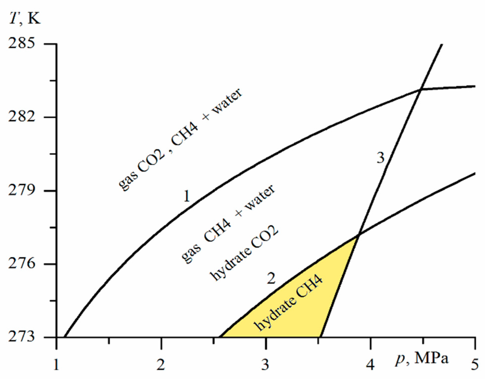
The continuous process of CO2 injection into a porous medium is studied in a one-dimensional linear approximation [37]. The problem is considered in a one-dimensional approximation; i.e., the presented mathematical model has a limited area of applicability. It is valid only for reservoirs with a sufficiently large thickness and width. In addition, the presented model corresponds to the simplest case of carbon dioxide injection, when injection occurs continuously for a long time and with a constant pressure. This choice is due to the fact that the present work aims to identify only the most important, general and universal laws of the process of replacement of methane in CH4 hydrate with carbon dioxide, which are independent of the specific method of the carbon dioxide injection into a gas hydrate deposit. Figure 1 shows the temperature and pressure conditions for the existence of hydrates CH4 and CO2. The ranges of pressures and temperatures corresponding to the stable existence of CO2 and CH4 hydrates are below curves 1 and 2, respectively. In this paper, it is supposed that the substitution process will be realized under thermobaric conditions corresponding to the existence of CH4 hydrate and CO2 hydrate, as well as the existence of carbon dioxide in the gaseous state (darkened area in the phase diagram).
As methane hydrate is less stable than carbon dioxide hydrate, under certain conditions, carbon dioxide molecules will replace methane molecules in gas hydrate without releasing free water [14,15].
Let the hydrate deposit at the initial moment of time consist of three components, namely the skeleton of a porous medium, methane and its hydrate.
For the skeleton, hydrate and gas, the subscripts sk, h and g are used, respectively; the subscripts i = dc, mt refer to the parameters of CO2 and CH4; Sg is the gas saturation; m is the reservoir porosity; υg(i) and (i = dc, mt) are the partial velocities and densities of the components of mixture carbon dioxide and methane; and Jg(mt) and Jg(dc) are the intensities of the CH4 release from hydrate and the CO2 transition to hydrate.
Depending on various factors, such as the composition and state of the gas, the pressure and temperature of the medium, the gas hydrate can have a diverse structure: from solid (ice-like) to porous (snow-like). In the case of the hydrate porous structure, during the replacement process, a mixed gas hydrate can be formed with a continuous distribution of the concentrations of CH4 and CO2 in the volume of the hydrate. However, in our work, we will consider the case when the hydrate has a continuous (ice-like) structure, so there is a clear boundary between CO2 and CH4 hydrates. Then, the value of volume hydrate saturation will be equal to
where Sh(i) is used for the saturation of pores with methane hydrate (i = mt) and the carbon dioxide hydrate (i = dc), where Sg + Sh = 1.
As the gas hydrate is immovable, we obtain
where G(i) and (i = dc, mt) are the relative mass of gas in the hydrate and the hydrate density, respectively.
We write the equation of H2O mass conservation in the hydrate in the following form:
Considering the initial state (Shd = 0, Shm = Shm0) in integrating this equation, we find the dependence of the phase saturation of CH4 hydrate and CO2 hydrate:
Note that the density of carbon dioxide hydrate is greater than the density of methane hydrate: , [2]. In the hydrates of CO2 and CH4 in the equilibrium state, there are about six molecules of H2O per gas molecule. It is considered that the average mass fraction of CO2 and CH4 in the hydrate are equal to G(dc) = 0.28 and G(mt) = 0.12, respectively. Therefore, the following relation is performed with good accuracy:
There is no release of H2O from the gas hydrate composition in the process of the CH4-CO2 exchange [20,21]. Hence, taking into account Equation (3), the following relation is valid for the intensities Jg(dc) and Jg(mt):
where M(dc) and M(mt) are the molar mass of carbon dioxide and methane.
For the gas mixture as a whole, we introduce the mass-average velocity:
Adding up the Equation (1), and then taking into account Equations (4) and (5), we obtain
To describe the mixture filtration and the diffusion mixing of its components, we will use the Darcy law and Fick’s law, respectively:
where Dg is the diffusion mixing coefficient of the components of gas mixture; and wg(i) (i = dc, mt) is the diffusion rate of the components of the methane and carbon dioxide mixture.
We assume that the mixture of methane and carbon dioxide is a calorically perfect gas and obeys the Dalton law:
where R(dc) and R(mt) are the specific gas constant of carbon dioxide and methane.
The equation for the internal energy of the system has the following form:
Here, the designation of the specific thermal conductivity and heat of the j-th phase are λj and cj (j = g, h) respectively; the designation of the specific heat of CH4 hydrate decomposition and CO2 hydrate formation are lh(mt) and lh(dc); the designations λ and ρc are used for the thermal conductivity and specific volume heat capacity.
The system of relations is supplemented by the following conditions:
where L is the linear reservoir size; T0 and p0 are the initial reservoir temperature and pressure; and Te and pe are the temperature and pressure of the CO2 injected into the layer.
2.2. Description of the CH4-CO2 Replacement Kinetics in the Hydrate
We accept that the rate of substitution of methane in the composition of gas hydrate with CO2 is limited by the diffusion of gas through the layer of CO2 hydrate formed between the gas phase and CH4 hydrate. The diffusing carbon dioxide with an average density of ρg(dc) in the hydrate will be called mobile, and the gas in the hydrate with a mass concentration Gi is immobile. Note that in connection with the adopted Equation (4), it becomes unnecessary to solve the inverse diffusion problem for the methane transfer through the hydrate layer of carbon dioxide.
We consider the following limiting scheme. We will assume that the skeleton of a porous medium is a set of channels with a cylindrical shape of radius a. In the presented model, it is assumed that CH4 hydrate completely covers the channel walls. For this case, CH4 hydrate will be located in the ring-shaped layer between r = a and r = a(dc), and CO2 hydrate in the layer between r = a(dc) and r = ag. Then, we obtain
For the process of the transfer of a diffusing gas through a layer of CO2 hydrate, we will use the diffusion equation [43,44]:
where Dh(dc) is the diffusion coefficient of CO2 in its hydrate; ρg(dc) is the average carbon dioxide density, which is dissolved in its hydrate.
Under the boundary conditions,
the quasi-stationary solution of Equation (13) is as follows:
where ρg(dc)s is the mobile carbon dioxide density in the CO2 hydrate for a saturated state.
The value of the mass of mobile carbon dioxide passing per unit of time through a unit contact surface area between CO2 and CH4 hydrates is equal to
Substituting Equation (15) into Equation (16), we obtain
The CO2 consumption intensity Jg(dc) is associated to the flow jg(dc): Jg(dc) = Ah jg(dc), where Ah is the total specific surface area of contact between CO2 and CH4 hydrates (i.e., the surface area of contact between the hydrates per unit volume of a reservoir). For this value in the framework of the adopted scheme, we obtain
where n(dc) is the number of channels with a diameter of 2a(dc) in the volume unit.
Using the analogy with Henry’s law, we will assume that the saturated concentration of free carbon dioxide in the composition of carbon dioxide hydrate is proportional to the partial pressure of carbon dioxide in the gas phase; i.e.,
where Γ(dc) is Henry’s parameter.
Then, for the intensity Jg(dc) of the carbon dioxide consumption for the formation of its hydrate per volume unit of porous medium, using Equations (17) and (18), we can write
We introduce a new empirical parameter, which will be called the reduced diffusion coefficient for carbon dioxide in a gas hydrate:
Substituting Equation (19) and the first equation from Equation (9) into the last formula, we obtain
In [45], based on the experimental data processing, the values of the methane diffusion coefficient through the gas hydrate layer were found to be of the order of 10−13 m2/s at the temperature of 274 K. By analogy with liquids, the diffusion coefficient Dh(dc) and Henry’s parameter Γ(dc) can be regarded as sufficiently conservative values (for example, weakly dependent on the value pg(dc)). Since the relative change in temperature for the processes under consideration is small, the reduced diffusion coefficient D will be considered constant. It should be mentioned that many factors can influence the intensity of the hydrate decomposition and formation, such as the introduction of various surfactants, the exposure of the shock and electromagnetic waves [46,47,48,49,50,51,52,53], etc. The empirical parameter D depends both on the hydrate structure and on the porous medium skeleton features.
We transform the above equations, using the independent variables , , and . The first equation from Equation (1), taking into account Equations (7) and (8), can be written as
As the second equation, we use Equation (6), which, taking into account Equation (7), will take the form
The heat influx in Equation (10), taking into account Equations (4) and (7), can be written in the form
To close this system, it is enough to add one more differential equation following from the first equation in Equation (2):
For other variable parameters included in Equations (23)–(26), taking into account Equations (12), (20) and (22), we obtain
Based on Equation (9) for pressure, we can get
In accordance with the above assumptions, the permeability of the gas mixture and the radius of porous tubules will be specified as
where is the absolute permeability coefficient of the porous skeleton.
We supplement the system of Equations (23)–(29) with the boundary and initial conditions:
The system of Equations (23)–(29) with the boundary and initial conditions in Equation (30) was solved by the finite difference method.
3. Calculation Results
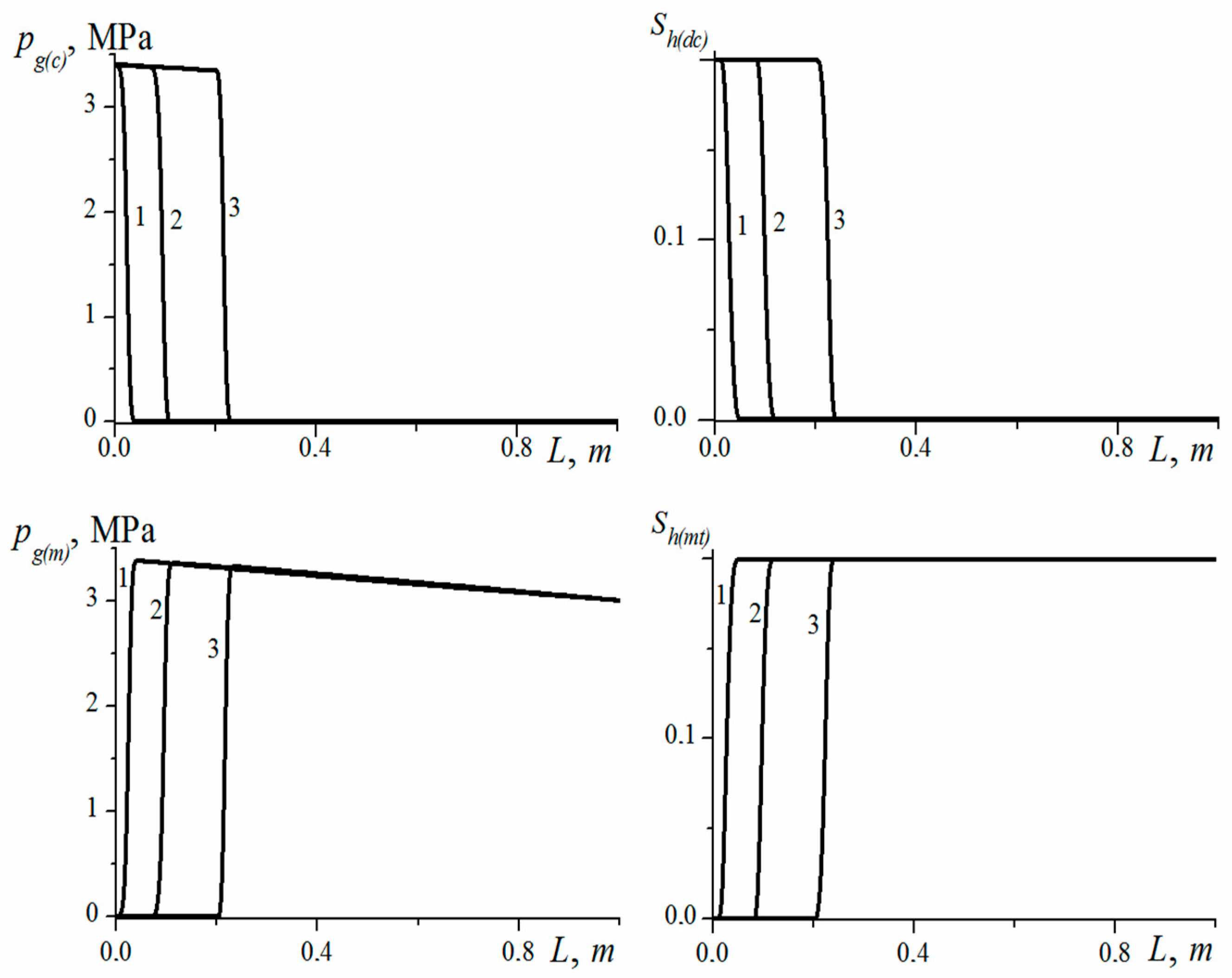
Figure 2 shows the distributions of the partial pressures and hydrate saturations of carbon dioxide and methane at k0 = 5 × 10⁻¹² m2, p0 = 3.1 MPa, D = 5 × 10⁻¹⁵ m2/s, T0 = 273 K. The original parameters used in the model are shown in Table 1 [11,16,19,39,54]. Note that the temperature fields in a reservoir will largely depend on the porous reservoir material, since it affects the values of thermal conductivity and specific volumetric heat capacity. The averaged values of the coefficients of thermal conductivity and specific volumetric heat capacity, characteristic of most reservoirs, are used in the work. The process will approach the frontal mode of hydrate substitution in the reservoir with a decrease in permeability. When implementing this mode, the reservoir is conventionally divided into two zones: the near one, containing carbon dioxide hydrate and the gas mixture CO2-CH4, and the far one, containing methane and its hydrate. In Figure 2, we can observe that the frontal mode is limited primarily by filtration mass transfer, and the role of diffusive mass transfer weakens.
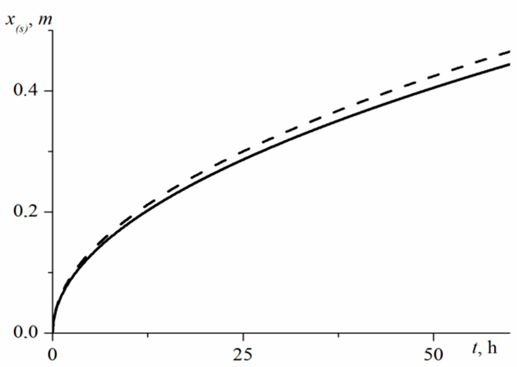
We used the approximate analytical solutions presented in [31] to test the mathematical model. In [31], approximate analytical solutions were obtained for the problem of decomposition of methane gas hydrate during the injection of gaseous CO2 into a gas-hydrated formation based on the method of converting to a self-similar variable.
Figure 3 presents the dependence of the coordinates of the hydrate substitution boundary in time. The solid line corresponds to the numerical solution obtained in our work with D = 10−16 m2/c, while the dashed line corresponds to the analytical solution obtained in [31]. The figure shows that these solutions show a fairly good agreement, which indicates the reliability of the mathematical model presented in our work.
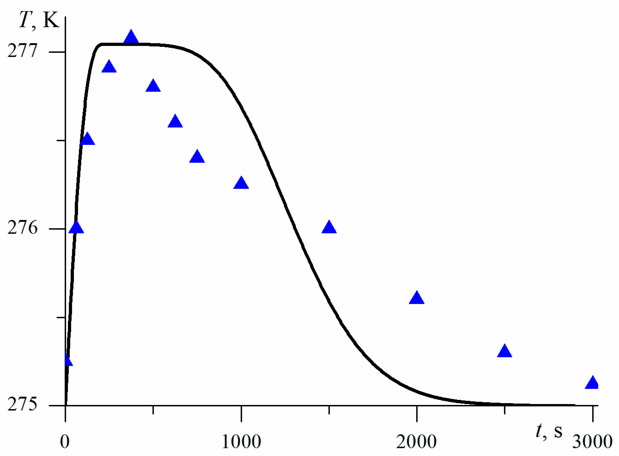
We also performed a comparison with the experimental data presented in [55]. In this work, the process of the replacement of methane in CH4 hydrate with CO2 in a dispersed medium is considered, and the dynamics of temperature changes for this process is presented. The experiment was carried out in two stages. The first stage was a test study of the methane hydrate formation in a quartz sand sample partially saturated with water. At the second stage of the experiment, the process of methane replacement with carbon dioxide in the hydrate saturated sand sample was studied. The initial methane hydrate saturation was 10%, the sample porosity was 34%, and the initial temperature in the reactor was 275 K.
Figure 4 shows a comparison of the results of numerical study and experimental data, given in [55], for changes in temperature over time. As can be seen from Figure 4, energy is released due to the replacement; after the completion of the CH4-CO2 replacement process, the sample temperature returns to the initial one. It is worth noting the satisfactory agreement between the experimental data and the calculation results using the proposed model.
Figure 5 represents the parameter distributions along the length of the reservoir at different of time instants at k0 = 10−16 m2, D = 10−16 m2/s, T0 = 274 K, p0 = 3 MPa; Ts(p) is the equilibrium temperature of phase transitions at the current pressure in the reservoir. It is shown that the injection of the CO2 into the reservoir leads to the increase of carbon dioxide partial pressure in the porous medium and to the initiation of the CH4 hydrate to CO2 hydrate transition process. The surface of the methane displacement by CO2 reaches the right border of porous medium in a time of about 1 min. Subsequently, methane is displaced, which was recovered from the gas hydrate as a result of the replacement process. The process of CH4-CO2 exchange in the methane hydrate occurs with the reservoir heating.
The mass flow rate of the gas passing through a unit cross-sectional area of the reservoir is equal to
where qg(dc)e is the specific mass flow rate of the injected CO2; and qg(dc) and qg(mt) are the specific mass flow rates of CO2 and CH4 at the reservoir outlet.
The specific (expressed per unit of the reservoir cross-sectional area) mass of the conserved CO2 Qg(dc) and the specific mass of the CH4 extracted from the reservoir Qg(mt) over a period of time T can be determined as follows:
Figure 6 shows the time dependences of the specific mass flow rates of the injected and extracted carbon dioxide, the mass flow rate of the extracted methane, the specific mass of carbon dioxide buried in the reservoir in the gas hydrate state, and the specific mass of the produced methane. It is evident that, at the initial stage, free methane is displaced from the reservoir. In the second stage, CH4 in the hydrate is replaced by CO2. As a result of the process of CO2 injection into the reservoir, about 35 kg/m2 of methane is extracted and about 115 kg/m2 of CO2 is stored.
The influence of various parameters on the time trep of the complete replacement of CH4 in hydrate with CO2 was studied.
Figure 7 shows the dependence of the time trep of complete replacement on the absolute reservoir permeability k; the dependence is constructed for two values of the reduced diffusion coefficient D. It can be seen that, at low values of the reservoir permeability, the reduced diffusion coefficient has little effect on the time of transition of CH4 hydrate in CO2 hydrate in the entire reservoir. This is due to the fact that, in the case with low values of the porous medium permeability k, the CH4-CO2 replacement process is limited by the mass transfer due to filtration. At high values of the reservoir permeability, the rate of the methane replacement in the CH4 hydrate with carbon dioxide significantly depends on the reduced diffusion coefficient magnitude D (Figure 7). We note that the increase in the replacement time, in the case of the growth in the porous media permeability k at the high values of the reservoir permeability, is due to the decrease in the specific contact surface between the CO2 hydrate and CH4 hydrate with an increased value of k.
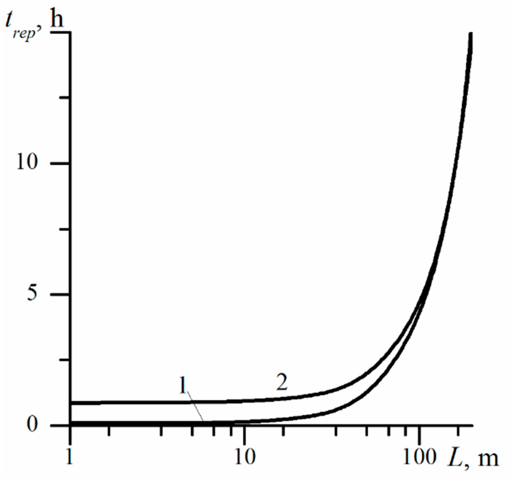
The dependence of the time trep of the total substitution of CH4 by CO2 in the CH4 hydrate on the hydrate saturated reservoir length is shown in Figure 8. It can be seen that, for short-length reservoirs with a decrease in permeability, the rate of hydrate of CH4 methane to the hydrate of CO2 transfer increases. This is due to the fact that, in this case, the process of the CH4-CO2 replacement is limited by diffusion, and a decrease in permeability corresponds to an increase in the specific contact surface between the hydrate and the gas. It is also worth noting that, in the case of a short-length reservoir, the complete CH4-CO2 replacement occurs at relatively short time intervals (Figure 8). As the length of the reservoir increases, the process of transition of CH4 hydrate to CO2 hydrate in the reservoir becomes increasingly dependent on the filtration mass transfer, which, in turn, depends significantly on the porous medium permeability. Therefore, in the case of long reservoirs, the time for the complete replacement of methane in the CH4 hydrate with carbon dioxide decreases with increasing the reservoir permeability.
Figure 9 shows the dependence of the time of full replacement trep on the reservoir length; the dependence is constructed for two values of the reduced diffusion coefficient D. It is evident that, as the reservoir length increases, the influence of the kinetics on the time of full transition of CH4 hydrate to CO2 hydrate decreases, and the role of the filtration mass transfer increases.
4. Conclusions
The process of methane replacement in gas hydrate with carbon dioxide during CO2 injection into a porous medium was studied. The calculations show that, for the process of CO2 injection into the gas hydrate reservoir, two stages can be distinguished. The first stage is specified by the beginning of the CH4-CO2 replacement process; in the second stage, methane, formed as a result of replacement, is extracted from the hydrate saturated reservoir.
It was established that at high values of the reduced diffusion coefficient of carbon dioxide in its hydrate, low values of the reservoir permeability, and with the growth of the reservoir length, the process of the CH4-CO2 replacement in CH4 hydrate will take place in the frontal regime. In this regime, the replacement process is determined primarily by the intensity of filtration mass transfer in the reservoir. Otherwise, the process of the CH4-CO2 replacement will occur in the volume area of the reservoir. In this case, the process is determined by the intensity of gas diffusion in hydrate. For the case of highly permeable porous media (the hydrate formation process is limited by the diffusion of gas in the hydrate), an increase in the methane replacement time in the CH4 hydrate with carbon dioxide is shown, which is caused by a decrease in the specific surface of contact between CH4 hydrate and CO2 hydrate with increasing reservoir permeability.
The presented mathematical model is more universal and allows us to consider the simultaneous influence of two factors (diffusion mechanism, filtration mass transfer) on the process under study.
Author Contributions
Conceptualization, M.K.K. and N.G.M.; methodology, M.K.K. and G.R.R.; software, G.R.R.; validation, M.K.K. and G.R.R.; formal analysis, M.K.K., N.G.M. and G.R.R.; investigation, M.K.K. and G.R.R.; writing—original draft preparation, M.K.K., N.G.M. and G.R.R. All authors have read and agreed to the published version of the manuscript.
Funding
This research was funded by Russian Science Foundation, grant number 17-79-20001.
Conflicts of Interest
The authors declare no conflict of interest.
References
- Makogon, Y.F. Hydrates of Hydrocarbons; PennWell Publishing Company: Tulsa, OK, USA, 1997. [Google Scholar]
- Makogon, Y.F. Natural gas hydrates—A promising source of energy. J. Nat. Gas Sci. Eng. 2010, 2, 49–59. [Google Scholar] [CrossRef]
- Makogon, Y.F.; Holditch, S.A.; Makogon, T.Y. Natural gas-hydrates—A potential energy source for the 21st Century. J. Pet. Sci. Eng. 2007, 56, 14–31. [Google Scholar] [CrossRef]
- Wang, Y.; Zhan, L.; Feng, J.-C.; Li, X.-S. Influence of the particle size of sandy sediments on heat and mass transfer characteristics during methane hydrate dissociation by thermal stimulation. Energies 2019, 12, 4227. [Google Scholar] [CrossRef] [Green Version]
- Vasil’ev, V.I.; Popov, V.V.; Tsypkin, G.G. Numerical investigation of the decomposition of gas hydrates coexisting with gas in natural reservoirs. Fluid Dyn. 2006, 41, 599–605. [Google Scholar] [CrossRef]
- Nazmutdinov, F.F.; Khabibullin, I.L. Mathematical modeling of gas desorption from a gas hydrate. Fluid Dyn. 1996, 31, 724–730. [Google Scholar] [CrossRef]
- Shagapov, V.S.; Yumagulova, Y.A.; Musakaev, N.G. Theoretical study of the limiting regimes of hydrate formation during contact of gas and water. J. Appl. Mech. Tech. Phys. 2017, 58, 189–199. [Google Scholar] [CrossRef]
- Chen, L.; Yamada, H.; Kanda, Y.; Okajimaa, J.; Komiya, A.; Maruyama, S. Investigation on the dissociation flow of methane hydrate cores: Numerical modeling and experimental verification. Chem. Eng. Sci. 2017, 163, 31–43. [Google Scholar] [CrossRef]
- Shagapov, V.S.; Khasanov, M.K.; Gimaltdinov, I.K.; Stolpovsky, M.V. The features of gas hydrate dissociation in porous media at warm gas injection. Thermophys. Aeromech. 2013, 20, 339–346. [Google Scholar] [CrossRef]
- Moridis, G.J. Numerical studies of gas production from methane hydrates. In Proceedings of the SPE Gas Technology Symposium, Calgary, AB, Canada, 30 April–2 May 2002. SPE 75691. [Google Scholar] [CrossRef]
- Musakaev, N.G.; Borodin, S.L.; Khasanov, M.K. The mathematical model of the gas hydrate deposit development in permafrost. Int. J. Heat Mass Transf. 2018, 118, 455–461. [Google Scholar] [CrossRef]
- Xu, T.; Jin, Y.-C. Simulation the convective mixing of CO2 in geological formations with a meshless model. Chem. Eng. Sci. 2018, 192, 187–198. [Google Scholar] [CrossRef]
- Zhang, H.; Cao, D. Molecular simulation of displacement of shale gas by carbon dioxide at different geological depths. Chem. Eng. Sci. 2016, 156, 121–127. [Google Scholar] [CrossRef] [Green Version]
- Safi, R.; Agarwal, R.K.; Banerjee, S. Numerical simulation and optimization of CO2 utilization for enhanced oil recovery from depleted reservoirs. Chem. Eng. Sci. 2016, 144, 30–38. [Google Scholar] [CrossRef]
- Misyura, S.Y.; Donskoy, I.G. Ways to improve the efficiency of carbon dioxide utilization and gas hydrate storage at low temperatures. J. CO2 Util. 2019, 34, 313–324. [Google Scholar] [CrossRef]
- Khasanov, M.K. Investigation of regimes of gas hydrate formation in a porous medium, partially saturated with ice. Thermophys. Aeromech. 2015, 22, 255–265. [Google Scholar] [CrossRef]
- Tsypkin, G.G. Formation of hydrate in injection of liquid carbon dioxide into a reservoir saturated with methane and water. Fluid Dyn. 2016, 51, 672–679. [Google Scholar] [CrossRef]
- Tsypkin, G.G. Formation of carbon dioxide hydrate at the injection of carbon dioxide into a depleted hydrocarbon field. Fluid Dyn. 2014, 49, 789–795. [Google Scholar] [CrossRef]
- Shagapov, V.S.; Khasanov, M.K.; Gimaltdinov, I.K.; Stolpovskii, M.V. Numerical modeling of formation of a gas hydrate in a finite-length porous bed purged by a gas. J. Appl. Mech. Tech. Phys. 2011, 52, 599–607. [Google Scholar] [CrossRef]
- Pandey, S.; Solms, N. Hydrate stability and methane recovery from gas hydrate through CH4-CO2 replacement in different mass transfer scenarios. Energies 2019, 12, 2309. [Google Scholar] [CrossRef] [Green Version]
- Horvat, K.; Kerkar, P.; Jones, K.; Mahajan, D. Kinetics of the formation and dissociation of gas hydrates from CO2-CH4 Mixtures. Energies 2012, 5, 2248–2262. [Google Scholar] [CrossRef]
- Deusner, C.; Bigalke, N.; Kossel, E.; Haeckel, M. Methane production from gas hydrate deposits through injection of supercritical CO2. Energies 2012, 5, 2112–2140. [Google Scholar] [CrossRef] [Green Version]
- Espinoza, D.N.; Santamarina, J.C. P-Wave Monitoring of hydrate-bearing sand during CH4-CO2 replacement. Int. J. Greenh. Gas Control 2011, 5, 1032–1038. [Google Scholar] [CrossRef]
- Chernov, A.A.; Dontsov, V.E. The processes of dissolution and hydrate forming behind the shock wave in the gas-liquid medium with gas mixture bubbles. Int. J. Heat Mass Transf. 2011, 54, 4307–4316. [Google Scholar] [CrossRef]
- Ohgaki, K.; Takano, K.; Sangawa, H.; Matsubara, T.; Nakano, S. Methane exploitation by carbon dioxide from gas hydrates-phase equilibria for CO2-CH4 mixed hydrate system. J. Chem. Eng. Jpn. 1996, 29, 478–483. [Google Scholar] [CrossRef] [Green Version]
- Ota, M.; Saito, T.; Aida, T.; Watanabe, M.; Sato, Y.; Smith, R.L.; Inomata, H. Macro and microscopic CH4-CO2 replacement in CH4 hydrate under pressurized CO2. AIChE J. 2007, 53, 2715–2721. [Google Scholar] [CrossRef]
- Falenty, A.; Qin, J.; Salamatin, A.N.; Yang, L.; Kuhs, W.F. Fluid composition and kinetics of the in situ replacement in CH4-CO2 hydrate system. J. Phys. Chem. C 2016, 120, 27159–27172. [Google Scholar] [CrossRef]
- Salamatin, A.N.; Falenty, A.; Kuhs, W.F. Diffusion model for gas replacement in an isostructural CH4-CO2 hydrate system. J. Phys. Chem. C 2017, 121, 17603–17616. [Google Scholar] [CrossRef]
- Tegze, G.; Granasy, L.; Kvamme, B. Phase field modeling of CH4 hydrate conversion into CO2 hydrate in the presence of liquid CO2. Phys. Chem. Chem. Phys. 2007, 9, 3104–3111. [Google Scholar] [CrossRef]
- Shagapov, V.S.; Musakaev, N.G.; Khasanov, M.K. Injection of liquid carbon dioxide into a reservoir partially saturated with methane hydrate. J. Appl. Mech. Tech. Phys. 2016, 57, 1083–1092. [Google Scholar] [CrossRef]
- Shagapov, V.S.; Khasanov, M.K.; Musakaev, N.G.; Duong, N.H. Theoretical research of the gas hydrate deposits development using the injection of carbon dioxide. Int. J. Heat Mass Transf. 2017, 107, 347–357. [Google Scholar] [CrossRef]
- McGrail, B.P.; Schaef, H.T.; White, M.D.; Zhu, T.; Kulkami, A.S.; Hunter, R.B.; Patil, S.L.; Owen, A.T.; Martin, A.T. Using Carbon Dioxide to Enhance Recovery of Methane from Gas Hydrate Reservoirs: Final Summary Report; Prepared for the U.S. Department of Energy under Contract DE-AC06-76RLO; Pacific Northwest National Laboratory: Richland, WA, USA, 2007; 1830p.
- White, M.D.; McGrail, B.P. Numerical simulation of methane hydrate production from geologic formations via carbon dioxide injection. In Proceedings of the Offshore Technology Conference, Houston, TX, USA, 5–8 May 2008. [Google Scholar]
- White, M.D. STOMP-HYDT-KE A Numerical Simulator for the Production of Natural Gas Hydrate Using Guest Molecule Exchange with Co2 and N2; Prepared for the U.S. Department of Energy under Contract DE-AC05-76RL01830; Pacific Northwest National Laboratory: Richland, WA, USA, 2012.
- Jiafei, Z.; Kun, X.; Yongchen, S.; Weiguo, L.; Weihaur, L.; Yu, L.; Kaihua, X.; Yiming, Z.; Xichong, Y.; Qingping, L. A review on research on replacement of CH4 in natural gas hydrates by use of CO2. Energies 2012, 5, 399–419. [Google Scholar] [CrossRef] [Green Version]
- Ota, M.; Abe, Y.; Watanabe, M.; Smith, R.L.; Inomata, H. Methane recovery from methane hydrate using pressurized CO2. Fluid Phase Equilib. 2005, 228–229, 553–559. [Google Scholar] [CrossRef]
- Byk, S.S.; Makogon, Y.F.; Fomina, V.I. Gas hydrates. Khimiya Mosc. 1980, 296. (In Russian) [Google Scholar]
- Bondarev, E.A.; Rozhin, I.I.; Popov, V.V.; Argunova, K.K. Underground storage of natural gas in hydrate state: Primary injection stage. J. Eng. Thermophys. 2018, 27, 221–231. [Google Scholar] [CrossRef]
- Bondarev, E.A.; Rozhin, I.I.; Popov, V.V.; Argunova, K.K. Assessment of possibility of natural gas hydrates underground storage in permafrost regions. Earth Cryosphere 2015, 19, 64–74. [Google Scholar]
- Bondarev, E.A.; Rozhin, I.I.; Popov, V.V.; Argunova, K.K. Mathematical modeling of natural gas underground storage in hydrate state. SOCAR Proc. 2015, 2, 54–67. [Google Scholar] [CrossRef]
- Musakaev, N.G.; Khasanov, M.K.; Rafikova, G.R. Mathematical model of the methane replacement by carbon dioxide in the gas hydrate reservoir taking into account the diffusion kinetics. AIP Conf. Proc. 2018, 1939, 020034. [Google Scholar] [CrossRef]
- Rafikova, G.R.; Khasanov, M.K. Modelling of process of displacement of methane from gas hydrate reservoir at dioxide carbon injection. J. Phys. Conf. Ser. 2019, 1268, 012063. [Google Scholar] [CrossRef]
- Shagapov, V.S.; Chiglintseva, A.S.; Rusinov, A.A.; Tazetdinov, B.I. Migration of a single gas bubble in water during the formation of stable gas-hydrate crust on its surface. Theor. Found. Chem. Eng. 2017, 51, 216–223. [Google Scholar] [CrossRef]
- Shagapov, V.S.; Rafikova, G.R.; Khasanov, M.K. On the theory of formation of gas hydrate in partially water-saturated porous medium when injecting methane. High Temp. 2016, 54, 858–866. [Google Scholar] [CrossRef]
- Salamatin, A.N.; Falenty, A.; Hansen, T.C.; Kuhs, W.F. Guest migration revealed in CO2 clathrate hydrates. Energy Fuels 2015, 29, 5681–5691. [Google Scholar] [CrossRef]
- Vlasov, V.A. Diffusion model of gas hydrate dissociation into ice and gas: Simulation of the self-preservation effect. Int. J. Heat Mass Transf. 2016, 102, 631–636. [Google Scholar] [CrossRef]
- Pahlavanzadeh, H.; Rezaei, S.; Khanlarkhani, M.; Manteghian, M.; Mohammadi, A. Kinetic study of methane hydrate formation in the presence of copper nanoparticles and CTAB. J. Nat. Gas Sci. Eng. 2016, 34, 803–810. [Google Scholar] [CrossRef]
- Nizaeva, I.G.; Makogon, Y.F. Impact of electromagnetic fields on nonconventional types of hydrocarbon feedstocks. Geol. Polezn. Iskop. Mirovogo Okeana 2013, 3, 42–54. (In Russian) [Google Scholar]
- Dontsov, V.E.; Chernov, A.A. Dissolution and hydrate-formation processes behind the shock wave in a gas-liquid mixture. Dokl. Phys. 2009, 54, 215–219. [Google Scholar] [CrossRef]
- Shagapov, V.S.; Yumagulova, Y.A. Automodel problem of the growth of the hydrate particle in aqueous solution of gas. Theor. Found. Chem. Eng. 2016, 50, 270–272. [Google Scholar] [CrossRef]
- Chernov, A.A.; Elistratov, D.S.; Mezentsev, I.V.; Meleshkin, A.V.; Pil’nik, A.A. Hydrate formation in the cyclic process of refrigerant boiling-condensation in a water volume. Int. J. Heat Mass Transf. 2017, 108, 1320–1323. [Google Scholar] [CrossRef]
- Madygulov, M.S.; Nesterov, A.N.; Reshetnikov, A.M.; Vlasov, V.A.; Zavodovsky, A.G. Study of gas hydrate metastability and its decay for hydrate samples containing unreacted supercooled liquid water below the ice melting point using pulse NMR. Chem. Eng. Sci. 2015, 137, 287–292. [Google Scholar] [CrossRef]
- Melnikov, V.P.; Nesterov, A.N.; Podenko, L.S.; Reshetnikov, A.M.; Shalamov, V.V. NMR evidence of supercooled water formation during gas hydrate dissociation below the melting point of ice. Chem. Eng. Sci. 2012, 71, 573–577. [Google Scholar] [CrossRef]
- Gimaltdinov, I.K.; Kildibaeva, S.R. Model of a submerged jet accounting for two limiting schemes of hydrate formation. Thermophys. Aeromech. 2018, 25, 75–83. [Google Scholar] [CrossRef]
- Castellani, B.; Gambelli, A.M.; Nicolini, A.; Rossi, F. Energy and environmental analysis of membrane-based CH4-CO2 replacement processes in natural gas hydrates. Energies 2019, 12, 850. [Google Scholar] [CrossRef] [Green Version]
Figure 1.
Curve of phase equilibrium CO2 + water (1), CH4 + water (2), gas CO2 + liquid CO2 (3).

Figure 2.
The distributions of partial pressures (pg(dc), pg(mt)) and hydrate saturations of carbon dioxide and methane. Lines 1, 2 and 3 correspond to t = 0.27, 2 and 5 h.
Figure 2.
The distributions of partial pressures (pg(dc), pg(mt)) and hydrate saturations of carbon dioxide and methane. Lines 1, 2 and 3 correspond to t = 0.27, 2 and 5 h.

Figure 3.
Dynamics of phase transition front coordinate. The solid line corresponds to the solutions obtained in this work, the dashed line in work [31].
Figure 3.
Dynamics of phase transition front coordinate. The solid line corresponds to the solutions obtained in this work, the dashed line in work [31].

Figure 4.
Comparison of calculated temperature with experimental data from [55]. The solid line is the numerical study results according to the proposed model, while the points are the experimental data.
Figure 4.
Comparison of calculated temperature with experimental data from [55]. The solid line is the numerical study results according to the proposed model, while the points are the experimental data.

Figure 5.
The distributions along the coordinate x of the partial pressures of CO2 pg(dc) and CH4 pg(mt), the reservoir temperature, the hydrate saturation Sh at various times moments. Curves 1, 2, 3, 4 correspond to t = 10, 30, 70 and 440 s. On the bottom right of the figure, solid lines correspond to Sh(dc), and dashed lines correspond to Sh(mt).

Figure 6.
Evolution with time of the specific mass flow rates of the CO2 injected into the layer qg(dc)e and produced from the reservoir qg(dc), the produced methane qg(mt), the specific mass of the conserved CO2 Qg(dc) and the specific mass of the produced CH4 Qg(mt).
Figure 6.
Evolution with time of the specific mass flow rates of the CO2 injected into the layer qg(dc)e and produced from the reservoir qg(dc), the produced methane qg(mt), the specific mass of the conserved CO2 Qg(dc) and the specific mass of the produced CH4 Qg(mt).

Figure 7.
Change of the time trep of the total methane replacement in CH4 hydrate with CO2 in the entire reservoir as a function of the reservoir permeability k at different values of the reduced diffusion coefficient D. Lines 1 and 2 correspond to D = 5 × 10⁻¹⁶ and 5 × 10⁻¹⁵ m2/s.
Figure 7.
Change of the time trep of the total methane replacement in CH4 hydrate with CO2 in the entire reservoir as a function of the reservoir permeability k at different values of the reduced diffusion coefficient D. Lines 1 and 2 correspond to D = 5 × 10⁻¹⁶ and 5 × 10⁻¹⁵ m2/s.

Figure 8.
Change of the time trep of the total methane replacement in methane hydrate with carbon dioxide depending on the reservoir length. Curves 1 and 2 correspond to k = 5 × 10⁻¹² and 5 × 10⁻¹³ m2.
Figure 8.
Change of the time trep of the total methane replacement in methane hydrate with carbon dioxide depending on the reservoir length. Curves 1 and 2 correspond to k = 5 × 10⁻¹² and 5 × 10⁻¹³ m2.

Figure 9.
Change of the time trep of the total methane replacement in methane hydrate with carbon dioxide depending on the reservoir length at different values of the reduced diffusion coefficient D. Lines 1 and 2 correspond to D = 4 × 10⁻¹⁵ m2/s and 4 × 10⁻¹⁶ m2/s.
Figure 9.
Change of the time trep of the total methane replacement in methane hydrate with carbon dioxide depending on the reservoir length at different values of the reduced diffusion coefficient D. Lines 1 and 2 correspond to D = 4 × 10⁻¹⁵ m2/s and 4 × 10⁻¹⁶ m2/s.


Table 1.
Basic parameters for the model.
| Variables | Symbol | Value | Unit |
|---|---|---|---|
| Porosity | m | 0.1 | - |
| Initial hydrate saturation | Sh(mt)0 | 0.2 | - |
| Reservoir length | L | 10 | m |
| Injection temperature | Te | 273 | K |
| Injection pressure | pe | 3.4 | MPa |
| Specific volumetric heat capacity | ρC | 2.5∙106 | J/(K∙m3) |
| System thermal conductivity coefficient | λ | 2 | W/(m∙K) |
| Mass concentrations of carbon dioxide in hydrate | G(dc) | 0.28 | - |
| Mass concentrations of methane in hydrate | G(mt) | 0.12 | - |
| Gas constant of methane | R(mt) | 520 | J/(kg∙K) |
| Gas constant of carbon dioxide | R(dc) | 189 | J/(kg∙K) |
| Density of carbon dioxide hydrate | ρh(dc) | 1115 | kg/m3 |
| Density of methane hydrate | ρh(mt) | 910 | kg/m3 |
| Dynamic viscosity of carbon dioxide | µg(dc) | 1.5·10−5 | Pa∙s |
| Dynamic viscosity of methane | µg(mt) | 1.12·10−5 | Pa∙s |
| Heat of the formation of CO2 hydrate | lh(dc) | 4.8·105 | J/kg |
| Heat of the formation of methane hydrate | lh(mt) | 4.37·105 | J/kg |
| Specific heat capacity of CO2 | cg(dc) | 731 | J/(kg∙K) |
| Specific heat capacity of methane | cg(mt) | 1560 | J/(kg∙K) |
| Diffusion mixing coefficient of the components of gas mixture | Dg | 10−5 | m2/s |
© 2020 by the authors. Licensee MDPI, Basel, Switzerland. This article is an open access article distributed under the terms and conditions of the Creative Commons Attribution (CC BY) license (http://creativecommons.org/licenses/by/4.0/).
Share and Cite
MDPI and ACS Style
Khasanov, M.K.; Rafikova, G.R.; Musakaev, N.G. Mathematical Model of Carbon Dioxide Injection into a Porous Reservoir Saturated with Methane and Its Gas Hydrate. Energies 2020, 13, 440. https://0-doi-org.brum.beds.ac.uk/10.3390/en13020440
AMA Style
Khasanov MK, Rafikova GR, Musakaev NG. Mathematical Model of Carbon Dioxide Injection into a Porous Reservoir Saturated with Methane and Its Gas Hydrate. Energies. 2020; 13(2):440. https://0-doi-org.brum.beds.ac.uk/10.3390/en13020440
Chicago/Turabian StyleKhasanov, Marat K., Guzal R. Rafikova, and Nail G. Musakaev. 2020. "Mathematical Model of Carbon Dioxide Injection into a Porous Reservoir Saturated with Methane and Its Gas Hydrate" Energies 13, no. 2: 440. https://0-doi-org.brum.beds.ac.uk/10.3390/en13020440
Note that from the first issue of 2016, this journal uses article numbers instead of page numbers. See further details here.