Article

Simplified Sensorless Current Predictive Control of Synchronous Reluctance Motor Using Online Parameter Estimation

1
Institute for Electrical Drive Systems and Power Electronics, Technical University of Munich (TUM), 80333 München, Germany
2
Electrical Engineering Department, Faculty of Engineering, Fayoum University, Fayoum 63514, Egypt
3
Electrical Engineering Department, Faculty of Engineering, Assiut University, Assiut 71516, Egypt
4
Electrical Engineering Department, Faculty of Engineering, Cairo University, Cairo 12613, Egypt
*
Author to whom correspondence should be addressed.
Submission received: 7 December 2019 / Revised: 12 January 2020 / Accepted: 14 January 2020 / Published: 19 January 2020
(This article belongs to the Special Issue Electric Machines and Drive Systems for Emerging Applications)

Abstract

:
In this paper, a simplified efficient method for sensorless finite set current predictive control (FSCPC) for synchronous reluctance motor (SynRM) based on extended Kalman filter (EKF) is proposed. The proposed FSCPC is based on reducing the computation burden of the conventional FSCPC by using the commanded reference currents to directly calculate the reference voltage vector (RVV). Therefore, the cost function is calculated for only three times and the necessity to test all possible voltage vectors will be avoided. For sensorless control, EKF is composed to estimate the position and speed of the rotor. Whereas the performance of the proposed FSCPC essentially necessitates the full knowledge of SynRM parameters and provides an insufficient response under the parameter mismatch between the controller and the motor, online parameter estimation based on EKF is combined in the proposed control strategy to estimate all parameters of the machine. Furthermore, for simplicity, the parameters of PI speed controller and initial values of EKF covariance matrices are tuned offline using Particle Swarm Optimization (PSO). To demonstrate the feasibility of the proposed control, it is implemented in MATLAB/Simulink and tested under different operating conditions. Simulation results show high robustness and reliability of the proposed drive.

1. Introduction

Recently, simple designed and rugged synchronous reluctance motors (SynRMs) have received more attention because they have low cost, high density, and Less complex control, in contrast to the induction motor [1,2]. Also, SynRM is considered a good substitution for permanent magnets synchronous motors and induction motors in commercial items and industrial applications like fans, electric vehicles, and washing machines [3]. Furthermore, the absence of the rotor windings and magnetic material results in higher energy efficiency and simple field weakening capability [4].
Traditionally, two widespread methods are preferred for SynRM drives: field-oriented control (FOC) and direct torque control [5]. FOC gives good steady-state response and is robust to variations of the machine parameters. However, its slow dynamic response is the main drawback [6]. DTC gives a fast dynamic response without using a modulator. However, high ripples in the current/torque are observed [6]. In [7], DTC with a space vector modulation (SVM) is proposed to reduce the high ripples in the torque and flux. To overcome the downsides of those controllers, researchers have engaged and presented a lot of adaptive control approaches to satisfy the demanded fast response and high performance in industrial applications. In the last years, model predictive control (MPC) is perceived as a favorable alternative to those both control methods. MPC technique has been applied to numerous types of motors, comprehensive induction machines [8], permanent magnet synchronous machines (PMSMs) [9], interior PMSMs [10], brush-less DC motors [11], and synchronous reluctance motor [12].
MPC has categorized into two groups, Finite set model predictive control (FSMPC), which considered a finite set of switching actions, and continuous set model predictive control (CS-MPC), which needs a modulation phase to produce the switching actions [13]. In specific, FSMPC techniques are very popular and attractive in the power electronics and drive applications due to their easiness of execution and the exceptionally dynamic performance given to the system under control [14,15,16]. FSMPC principles proceed into account the switching states of the inverter instead of using modulator. A discrete-time model of the system is required to predict the future behavior of the system (one sampling time or more) for all the possible switching vectors [17]. The control objectives of the FSMPC techniques are indicated in the formula of a cost function, which gives the conditions for selecting the best switching action to apply in the next sampling interval. Furthermore, current and voltage constraints can be realized as apart of the cost function. The FSMPC approaches are commonly categorized into current predictive control (CPC), torque predictive control (TPC), and speed predictive control (SPC) [18]. In CPC schemes, the stator currents are considered the controlled variables, whereas the torque and flux are used as the controlled variables in TPC schemes [19]. The SPC strategy removes the outer PI speed controller in CPC and TPC schemes, however tuning of numerous weighting factors is essential [19]. Due to the curbs of SPC strategies, applications of both CPC and TPC schemes are more prevalent for electric drives. In [20], the model predictive control illustrated sufficient performance than a traditional PI controller. Also, the predictive control is used to control the speed and currents of SynRM, which overcomes the limitations of cascaded loops, as in [21]. FSMPC of synchronous reluctance motor based on the active flux concept is illustrate in [20]. Nevertheless, The authors use the nominal values of the machine parameters in the prediction model. One of the crucial challenges of the conventional finite set current predictive control (FSCPC) is its extreme computational potential [22]. Such as, for two-level inverters, seven iterations for both the current prediction and cost function are essential. For that reason, a powerful digital signal processor (DSP) is needed to implement the conventional FSCPC [14]. So as to diminish the computational load, some MPC approaches have been suggested to solve this problem as in [23,24]. However, all the presented methods are sensitive to system parameters variation. Also, the measured currents are used directly at the prediction step which generates unsought switching states. Consequently, the controller produces a high total harmonic distortion (THD).
Furthermore, to implement the proposed control method, the position and speed of the rotor and the measured currents should be fed back to the predictive model. Usually, this is achieved by a mechanical encoder and sensor currents. Furthermore, these measurement instruments increase the cost/noise and reduce the reliability of the entire system. Besides, in low-cost applications, the position accuracy usually is an insignificant concern. These previous reasons have been encouraged the researchers to propose sensorless control of electrical drives.
In recent decades, several sensorless control strategies have been executed for the synchronous reluctance motor [25,26]. These strategies can be classified into two groups. The first group based on the fundamental models of the machine such as model reference adaptive system (MRAS), sliding mode observer (SMO), disturbance observer, and extended Kalman filter (EKF) [27]. The second group is based on an Anisotropic method, which is preferred for low and zero speed regions such as high-frequency signal injection methods [27]. The extended Kalman filter is a popular technique for sensorless control and is considered the optimal recursive observer in the least square sense for nonlinear dynamic systems. EKF is considered very proper for the systems with parameters variation and noisy measurements. EKF has been extensively employed for sensorless control of PMSMs/IMs and SynRM as in [28,29,30,31]. The EKF based on parameter identification method for synchronous motor and IPMSM has been described in [32,33]. Nonetheless, the main downsides of the EKF are the tuning and design of the covariance matrices. In [30], some guidelines are used to obtain these matrices. However, this method still based on a trial and error method.
On the other hand, there are only a limited number of researches combine the sensorless control with predictive control. The main reason is the complication results in merging these two controllers, which motivate us to do this work. In [34], the sensorless predictive control of synchronous reluctance motor based on high-frequency injection is presented. The sensorless control is joined with predictive current control for the IPMSM in [35]. However, these methods do not consider the effect of parameter uncertainties.
In this paper, sensorless and computationally-efficient current predictive control of synchronous reluctance motor based on extended Kalman filter is proposed. The main idea of the proposed FSCPC strategy is that the commanded reference currents are directly used to calculate the reference voltage vector (RVV). Then, the RVV location is determined by its angle. Last, the cost function is calculated only three times to get the best switching vector. Accordingly, the seven predictions of the current and seven evaluations of the cost function using the traditional FSCPC are avoided. To enhance the reliability of the drive system and improve the robustness of the proposed FSCPC, an online estimation using the Extended Kalman filter is combined with the proposed FSCPC to estimate the SynRM parameters. The proposed strategy estimates the position and speed of the rotor, d q stator currents, d q stator inductances, and stator resistance. The load torque is also observed using EKF to improve the load variation problem. In addition, to avoid the trial and error method in the tuning of the EKF parameters, Particle Swarm Optimization (PSO) is used to tune these parameters. The proposed FSCPC is validated by simulation results and its performance is compared with the traditional FSCPC under various operation conditions.
The rest of the paper is structured as follows. Section 2 indicates mathematical modeling of synchronous reluctance motor and discrete-time mode. Section 3 proposes the EKF and Section 4 clarifies the conventional FSCPC and the proposed FSCPC and Section 5 illustrates the simulation results. The conclusion of the paper is presented in Section 6.

2. Synchronous Reluctance Motor Modeling

In this study, the linear SynRM modeling without saturation is considered. However, the compensation of Parameter variations will be done by online parameter estimation using EKF. The SynRM coordinates are shown in Figure 1a, where α β are the stationary coordinates and d q are the rotating rotor coordinates. The stator voltages, flux linkage, the electromechanical torque, and speed dynamic equations of synchronous reluctance motor in the continuous time model can be written as follows [36],
v s d ( t ) = R s i s d ( t ) + d d t ψ s d ( t ) ω r ψ s q ( t ) , v s q ( t ) = R s i s q ( t ) + d d t ψ s q ( t ) + ω r ψ s d ( t ) , ψ s d ( t ) = L d i s d ( t ) , ψ s q ( t ) = L q i s q ( t ) , T e ( t ) = 3 2 P [ L d L q ] i s d ( t ) i s q ( t ) , = 3 2 P [ L d L q ] I s 2 sin γ cos γ , d d t ω m ( t ) = 1 J [ T e ( t ) T L B ω m ( t ) ] ,
where, ( v s d , v s q ) , ( i s d , i s q ) , and ( ψ s d , ψ s q ) are the stator voltages, stator currents, and stator fluxes in the rotating reference frame, respectively. L d and L q is direct axis and quadrature axis inductance respectively, R s is the stator resistance. ω r and ω m are the motor electrical and mechanical speed, respectively, note, ω r = P ω m . T e is the electromechanical torque and T L is the mechanical load torque applied. γ and I s are the current angle and absolute value of stator current. J and B are the overall inertia of the rotor and the coefficient of viscous friction respectively and P is number of pair poles.
To design the EKF for estimation of the position and speed of the rotor, stator currents, load torque, and SynRM parameters, the state-space model representation of the SynRM is presented in d q frame. In contrast, the inputs currents and voltages fed into EKF are in α β frame and rotating frame transformation is applied in the measurement matrix [37]. The load torque, stator resistance, and stator inductances are also taken as state variable, which are presumed to be constant over a small interval of sampling time T s . The state-space model of SynRM can be expressed as
x ˙ = g ( x , u ) , y = h ( x ) ,
where x , y , and u are the state, output, and input vectors, respectively, and are described as
x = i s d i s q ω r θ r T L R s L q L d T , y = i s α i s β T , u = u s α u s β T .
The function of g ( x , u ) , h ( x ) can be deduced from (1) as follows
g ( x , u ) = R s L d i s d + L q L d ω r i s q + cos θ r L d u s α + sin θ r L d u s β R s L q i s q L d L q ω r i s d sin θ r L q u s α + cos θ r L q u s β 3 P 2 2 J [ L d L q ] i s d i s q P T L J ω r 0 0 0 0 , h ( x ) = cos θ r sin θ r 0 0 0 0 0 0 sin θ r cos θ r 0 0 0 0 0 0 x .

3. The Proposed Extended Kalman Filter Estimator

Extended Kalman filter is a nonlinear extension of kalman filter for linear system and is implemented on discrete nonlinear state model. For discretization, the forward Euler method is applied on (2) with sampling time T s [ s ] as in [28].
x ( k + 1 ) = x ( k ) + T s g ( x ( k ) , u ( k ) ) + w ( k ) , y ( k ) = h ( x ( k ) ) + v ( k ) ,
where, w ( k ) is represented the system uncertainties with covariance matrix Q = E [ w ( k ) w ( k ) T ] , and v ( k ) is measurement noise with covariance matrix R = E [ v ( k ) v ( k ) T ] which are represented as follows,
Q = d i a g { q 11 , q 22 , q 33 , q 44 , q 55 , q 66 , q 77 , q 88 } , R = d i a g { r 11 , r 22 } .
The parameters of covariance matrices have an excessive influence on the response and EKF convergence. Therefore, they are obtained using the particle swarm optimization technique, which is presented in the next section.
The EKF estimation algorithm can be concluded in the following steps as illustrated in Figure 1b [28,38].
  • State vector and covariance matrices initialization, x 0 = x ( t 0 ) , Q, and R are set with initial values that obtained using offline PSO.
  • State vector Prediction x ^ * at sampling time ( k + 1 ) as follows,
    x ^ * ( k + 1 ) = x ( k ) + T s g ( x ( k ) , u ( k ) ) = f ( x ^ ( k ) , u ( k ) ) .
  • Covariance matrix Prediction.
    P * ( k + 1 ) = A ( k + 1 ) P ^ ( k ) A T ( k + 1 ) + Q .
    where, A is the Jacobian matrix as:
    A ( k + 1 ) = ( x ) [ f ( x , u ) ] x = x ^ ( k ) .
    Therefore, the Jacobian matrix is calculated from (9) as follows,
    A = 1 T s R s L d T s L q L d ω r T s L q L d i s q J 14 0 T s i s d L d T s i s q L d ω r J 18 T s L d L q ω r 1 T s R s L q T s L d L q i s d J 24 0 T s i s q L q J 27 T s i s d L q ω r T s 3 P 2 2 J [ L d L q ] i s q T s 3 P 2 2 J [ L d L q ] i s d 1 0 T s P J 0 J 37 J 38 0 0 T s 1 0 0 0 0 0 0 0 0 1 0 0 0 0 0 0 0 0 1 0 0 0 0 0 0 0 0 1 0 0 0 0 0 0 0 0 1 ,
    where; J 14 = T s u s α sin θ r + u s β cos θ r L d , J 14 = T s u s α cos θ r + u s β sin θ r L q ,
    J 18 = T s R s i s d L d 2 T s L q i s q L d 2 ω r T s u s α cos θ r L d 2 T s u s β sin θ r L d 2 ,
    J 27 = T s R s i s q L q 2 T s L d i s d L q 2 ω r + T s u s α sin θ r L q 2 T s u s β cos θ r L q 2 , J 37 = T s 3 P 2 2 J L d i s d i s q , and J 38 = T s 3 P 2 2 J L q i s d i s q ,
  • Kalman filter gain computation:
    K ( k + 1 ) = P * ( k + 1 ) h T ( k + 1 ) [ h ( k + 1 ) P * h T ( k + 1 ) + R ] 1 ,
    where,
    h ( k + 1 ) = ( x ) [ h ( x ) ] x = x * ( k + 1 ) .
    Using (4) and (11), h ( k + 1 ) can be deduced as
    h ( k + 1 ) = cos θ r sin θ r 0 i s d sin θ r i s q cos θ r 0 0 0 0 sin θ r cos θ r 0 i s d cos θ r i s q sin θ r 0 0 0 0 .
  • Updating of state-vector:
    x ^ ( k + 1 ) = x ^ * ( k + 1 ) + K ( k + 1 ) [ y ( k + 1 ) y ^ ( k + 1 ) ] ,
    y ^ ( k + 1 ) = { h ( x ) } x ^ * ( k + 1 ) .
  • Error covariance matrix estimation:
    P ^ ( k + 1 ) = P * ( k + 1 ) K ( k + 1 ) h ( k + 1 ) P * ( k + 1 ) .
  • Put k = k + 1 , x ( k ) = x ( k + 1 ) , P ( k ) = P ( k + 1 ) and go back to step 2.
    From the last steps of EKF, it can be revealed that the choice of covariance matrices parameters Q and R play an important role to get a sufficient estimation for EKF state variables. Furthermore, the parameters of K p , K i of the speed controller play a significant part in the performance and robustness of the drive. Furthermore, tuning of these parameters ( Q , R , K p , and K i ) efficiently consume a lot of time. Consequently, the particle swarm optimization (PSO) algorithm is used to tune these parameters.
    PSO is considered the most active procedure in solving different types of optimization problems with a little number of parameters to adjust [39]. This provides better efficiency than other trial and error methods. Firstly, PSO selects some set of random values of the unknown parameters and each set is represented as a particle. The objective function corresponding to each particle is calculated using the current position of each particle. Then, the particle corresponds to optimum objective value is selected and recorded after each iteration of the algorithm, and finally produces the global optimum solution [40,41]. In this model drive, the cost (objective) functions which used to select the best parameters is represented as follows.
    m i n ( ω c o s t ) = ( ω r e f ω ^ r ) m i n ( I d q c o s t ) = ( I s , r e f d q I ^ s d q ) m i n ( ω ^ c o s t ) = ( ω r ω ^ r )
    Apply the PSO in the whole drive system. Then, the following parameters have been selected.
    Q = d i a g { 0.0050 , 0.0843 , 259.3880 , 3.2316 e 4 , 3.9388 , 4.8648 , 5.9060 e 4 , 3.2048 e 4 } R = d i a g { 0.0789 , 0.0741 } P 0 = d i a g { 1 , 1 , 1 , 1 , 1 , 1 , 1 , 1 } X 0 = ( 0 , 0 , 0 , 0 , 0.01 , 0 , 0.01 , 0.01 ) T K P = 0.1305 , K I = 0.08947

4. Finite-Set Current Predictive Control of SynRM

In this work, the well-known three-phase two-level voltage-source inverter is coupled to the SynRM as displayed in Figure 2, with dc-link voltage equal V d c , and S a S ¯ c are the six switches of the inverter. The different eight switching states of the inverter designated as u 0 u 7 , and the corresponding voltage vectors in stationary reference frame α β are listed in Figure 2 and Table 1. Then, Park transformation is provided to convert the stator voltages into rotating frame d q as in [15]. The conventional and proposed Current predictive control of synchronous reluctance motor are presented in the following sections.

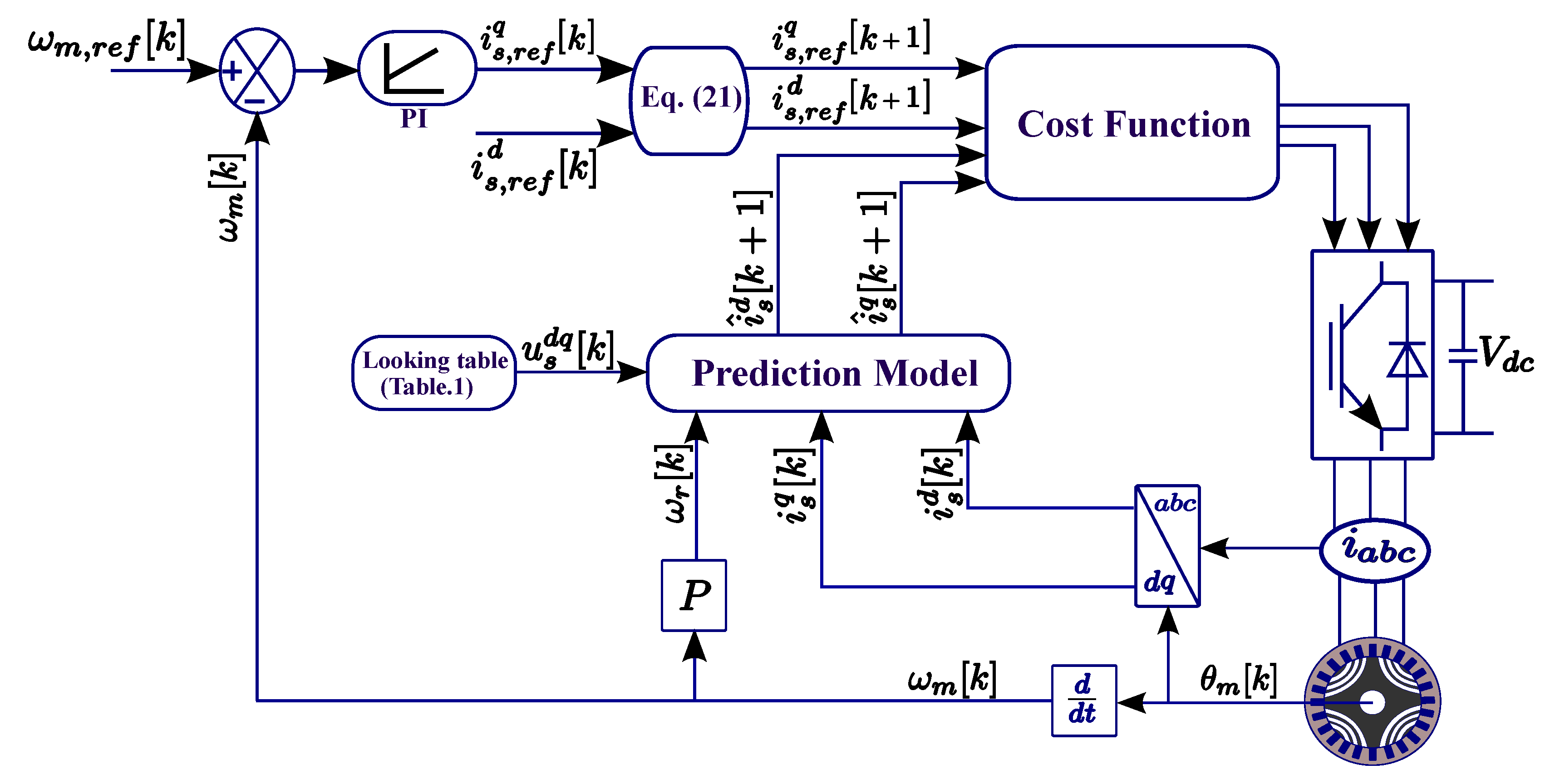
4.1. Conventional FSCPC of SynRM

The block diagram of the conventional FSCPC of SynRM is shown in Figure 3. To design the conventional FSCPC strategy, (1) is used to get d d t i d q ( t ) as
d d t i s d ( t ) = R s L d i s d ( t ) + L q L d ω r ( t ) i s q ( t ) + u s d ( t ) L d d d t i s q ( t ) = R s L d i s q ( t ) L d L q ω r ( t ) i s d ( t ) + u s q ( t ) L q
A discrete-time model is required to predict the currents for the next sampling time. Consequently, the forward Euler method is applied to the continuous-time model in (17) for small sampling time T s . Therefore, the discrete-time model of the SynRM in the rotating reference frame d q can be written as [1,14]
i s d [ k + 1 ] = ( 1 T s R s L d ) i s d [ k ] + T s L q L d ω r [ k ] i s q [ k ] + T s u s d [ k ] L d i s q [ k + 1 ] = ( 1 T s R s L q ) i s q [ k ] + T s L d L q ω r [ k ] i s d [ k ] + T s u s q [ k ] L q
The stator voltages u s d q can be represented as a function of the switching vectors S a b c of the two-level inverter as in [1,13]:
u s d q [ k ] = T P ( θ ^ r ) 1 · T C · V d c · S S 2 3 ( S a + a S b + a 2 S c )
Where, T C and T P ( θ r ) 1 are the Clarke and inverse Park transformation, respectively, as in [14]. a = e j 2 π 3 and ( S a , S b , S c ) represent the switching states of each leg of the inverter as shown in Table 1. These different seven vectors can be applied to predict seven future values of the current according to (18). Then, the seven predicted future values are applied in the cost function with soft constraints to select the optimal switching vector that achieve the minimum absolute error between the reference and predictive currents [13]. The cost function formula can be written as
g = | i s , r e f d ( k + 1 ) i s d ( k + 1 ) | u 0 , . . , 7 | + | i s , r e f q ( k + 1 ) i s q ( k + 1 ) | u 0 , . . , 7 | + 0 if i s d ( k + 1 ) 2 + i s q ( k + 1 ) 2 i s , m a x if i s d ( k + 1 ) 2 + i s q ( k + 1 ) 2 > i s , m a x ,
where i s , m a x the maximum allowable stator currents of SynRM, and i s , r e f d q ( k + 1 ) are the reference stator currents in d q frame. It can be computed from the previous reference currents i s , r e f d q ( k ) as in [13].
i s , r e f d q ( k + 1 ) = 3 i s , r e f d q ( k ) 3 i s , r e f d q ( k 1 ) + i s , r e f d q ( k 2 )
The main weaknesses of the conventional FSCPC are as follows. (1) High calculation burden (seven predictions of the currents and seven evaluations of the cost function), (2) sensitivity to variations of the SynRM parameters due to the use of constant parameters in (18), and (3) an encoder is essential to measure the speed and position of the rotor (i.e., high cost and low reliability of the drive system).

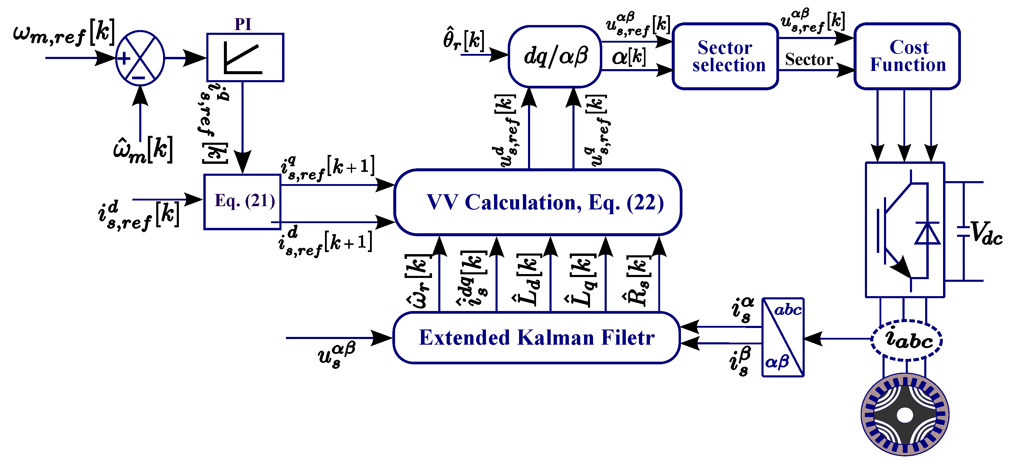
4.2. Proposed FSCPC of SynRM

Figure 4 reveals the proposed FSCPC of SynRM, its based on computing the reference voltage vector (RVV) directly from the reference currents. Furthermore, online parameters estimation of SynRM based on EKF is combined with the proposed method. The estimated currents (filtered) and estimated SynRM parameters are used in the prediction model to improve the robustness for the proposed method. Using (18), the RVV can be computed by replacing i s d q [ k + 1 ] with i s , r e f d q [ k + 1 ] as
u s , r e f d ( k ) = R ^ s ( k ) i ^ s d ( k ) + L ^ d ( k ) i s , r e f d ( k + 1 ) i ^ s d ( k ) T s ω ^ r ( k ) L ^ q ( k ) i ^ s q ( k ) u s , r e f q ( k ) = R ^ s ( k ) i ^ s q ( k ) + L ^ q ( k ) i s , r e f q ( k + 1 ) i ^ s q ( k ) T s ω ^ r ( k ) L ^ d ( k ) i ^ s d ( k )
where, ∧ indicates the estimated values for EKF observer. Then, using Park transformation, The reference voltages are transformed into the stationary reference frame α β . Consequently, its location can be determined by its angle as cleared in Figure 2:
α ( k ) = a t a n 2 [ u s , r e f β ( k ) , u s , r e f α ( k ) ]
Now, the corresponding cost function can be written as
g = | u s , r e f α ( k ) u s α ( k ) | + | u s , r e f β ( k ) u s β ( k ) |
where the six sectors are defined as in Figure 2; the sector of the RVV is selected based on its location from (23). For interpretation, when α ( k ) [ 0 , π 3 ] ; then, the u s α β ( k ) are situated in sector 1 and the only voltage vectors ( u 0 , u 1 , and u 2 ) as illustrated in Figure 2 are applied in the cost function (24).
In conclusion, the proposed FSCPC significantly reduces the calculation load of the traditional FSCPC. Furthermore, in (22), the parameters of the SynRM ( R ^ s , L ^ d , and L ^ q ) are online estimated by the EKF, which improve the robustness of the proposed FSCPC against variations of the machine parameters (i.e., if the parameters vary, the EKF will detect the new values of the parameters and update them in (22)). Additionally, EKF estimates also the speed and position of the rotor, i.e., no encoder is required. Finally, the filtering ability of the EKF is employed to filter the stator currents of the SynRM, which reduces the ripples of the torque.
Note that in SynRM, addition torque ripples is caused by the variation of magnetic resistance between flux barriers and teeth, which can be solved by asymmetrically design of the flux barriers [42]. Another alternative is an optimization of the shape of the symmetrical rotor flux barriers considering the number of stator teeth [43]. In this work, the ripples caused by the stator currents are only considered.

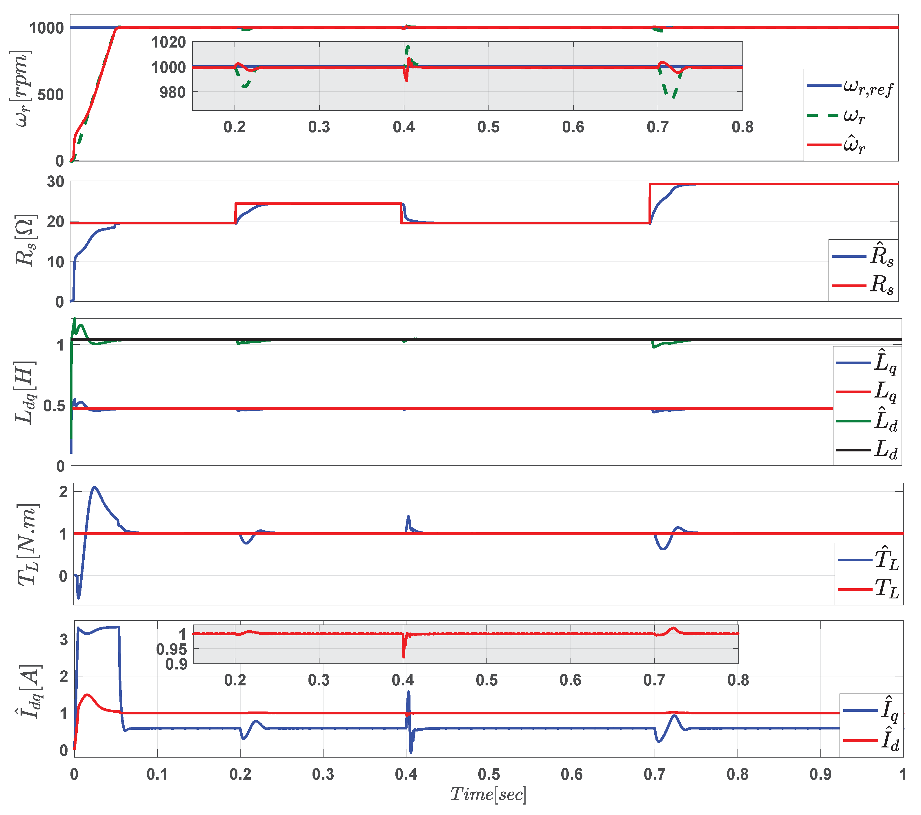
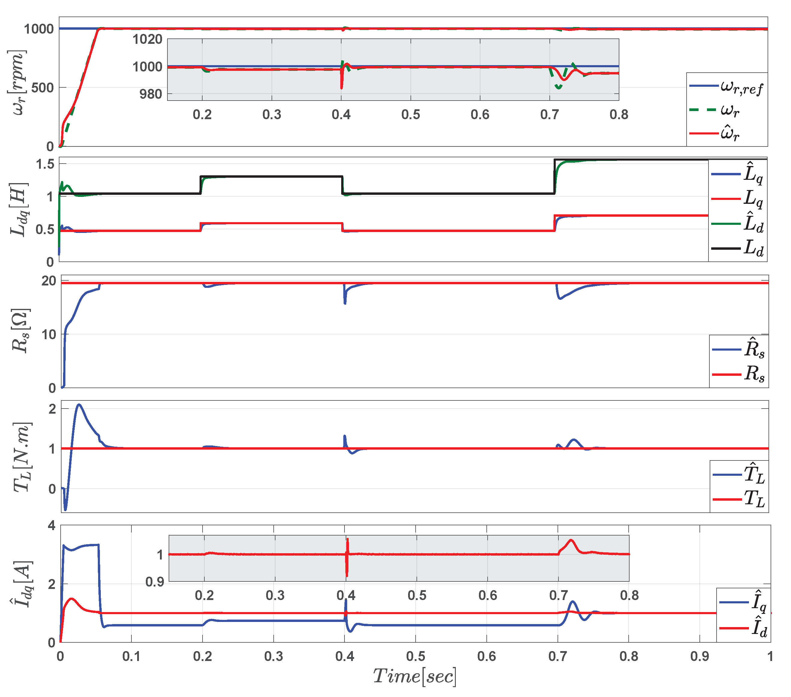
5. Simulation Results

The simulation model of the proposed FSCPC of SynRM as shown in Figure 4, is simulated and verified with the help of MATLAB/SIMULINK. The nominal parameters of SynRM are summarized in Table 2. Firstly, PSO has applied to choose the optimum unknown parameters for a wide speed range as in (16). The value of the sampling time has a great impact on the control system of the motor such as torque and current ripples. Therefore, the sampling time is selected to be 40 μ s, which provides sufficient torque and current ripples. Second, as revealed in Figure 4, the measured three-phase voltages and currents of SynRM are transformed into two-phase stationary frame α β . These signals are used as inputs to EKF to estimate all the state variables of SynRM, which are the position and speed of the rotor, stator currents ( I d q ) , armature stator resistance ( R s ) , and stator inductances ( L d q ) . The estimated variables are fed-back into the prediction model. The estimated speed ω ^ r is compared to the reference speed ω r , r e f to get the error which used as input to the PI controller to produce I q , r e f . In this work, I d , r e f is selected as the rated current of the motor (1 A). The simulation results are cleared in Figure 5, Figure 6, Figure 7, Figure 8, Figure 9, Figure 10 and Figure 11. The observation performances of presented EKF are compared with the nominal values of the SynRM for a wide speed range including the low and reversal speed. Furthermore, the effect of parameters uncertainties in the sator resistance R s and inductances L d q of the SynRM are verified using EKF.
Figure 5 reveals the simulation results of the estimation capability of the EKF of the speed and position of the rotor, stator resistance R s , stator inductances L d q , load torque, and stator currents I d q at the middle and high speed. According to the figure, mechanical speed begins with 400 rpm, then changes to 700 rpm at 0.3[s], then up to 1000 rpm, and 1300 rpm at times 0.6[s] and 0.8[s], respectively, with applying a load torque of 1 N.m. From the figure, it is clear that EKF has a sufficient estimation accuracy in the dynamic and steady-state operation. Also, the speed and position errors converge to zero quickly. The estimation of The armature resistance ( R s ) and stator inductances ( L d , L q ) also converge to the nominal values of the SynRM with an estimation error at start-up. Finally, the estimation of the load torque ( T L ) and stator currents ( I d q ) are shown in Figure 5. It can be seen that the estimated values track the actual values with adequate performance.
In Figure 6, the previous operating condition is repeated but at low, zero, and reversal speed. It can be illustrated that the EKF observation capability has good tracking for all state variables with high performance at dynamic and steady-state. Also, it can be established that there is a close agreement with the actual parameters of the machine regardless of initial errors.
To check the facility strength of the proposed EKF under parameter deviations of the SynRM, the value of the stator resistance R s is increased by 25% at 0.2[s] and returned to its nominal value for 0.3[s], and increased again by 50% under speed of 1000 rpm. The values of stator inductances ( L d , L q ) are set to the actual values. The results are shown in Figure 7. From the figure, the tracking performance of the resistance is very good with adequate accuracy. However, the change of the stator resistance value causes a small dynamic estimation error in the other estimated variables as illustrated also in Figure 7. Additionally, to reveal the capability of the proposed method in tracking the variations in the direct and quadrature axis inductances that changed with magnetic saturation. As seen in Figure 8, the direct and quadrature axes inductances ( L d , L q ) increased by 25% and 50% at times 0.3[s] and 0.6[s], respectively, under speed of 1000 rpm and load torque 1 N.m. The EKF exposes a good tracking performance at dynamic/stead-state during inductances variation. Finally, the proposed EKF is checked for load torque variation and its impacts on the parameters of the machine as shown in Figure 9. Where the load torque in 1 N.m is applied on the machine and then changed to 1.5 N.m. According to the figure, the EKF succeeded in following the variation of the load toque with quite high performance.
In Figure 10 and Figure 11, the robustness of the proposed FSCPC to parameters variation of the machine is investigated and compared with the conventional FSCPC. In Figure 10a, the stator resistance increased by 25% than the nominal value at t = 0.2[s], then increased to 50% of its actual value at t = 0.4[s]. The rotor mechanical speed set to 1100 rpm with mechanical load torque 1 N.m, and nominal values of stator inductances. It can be perceived from this figure that the proposed FSCPC gives good performance compared to the conventional FSCPC. Furthermore, the mean value of the steady-state error of the proposed method is close to zero, while, a non-zero of the steady-state error has appeared in the conventional one. Also, the stator currents I d q of the conventional technique deviate due to resistance changing. Additionally, the investigation of the robustness to inductances L d q variations of the SynRM is shown in Figure 10b. The inductances increased by 50% of its nominal value at t = 0.2[s] and the value of stator resistance set to the actual value. Also, the rotor mechanical speed is set to 1100 rpm with load torque 1 N.m. From Figure 10b, the performance of the proposed method is better than the conventional one. The q-axis current of the conventional method oscillates due to the inductance variations. Finally, the speed response, stator currents, and torque ripples of the SynRM for the proposed and conventional FSCPC are explored and compared in Figure 11. The mechanical rotor speed set to rated speed 1500 rpm with 1 N.m mechanical load. It can be revealed from the figure that the dynamic performance of the proposed FSCPC is faster than the conventional one. The total harmonic distortion (THD) of the proposed method is better than the conventional one. Also, the torque ripples are remarkably smaller for the proposed FSCPC compared with the conventional one. The dissimilarities between the proposed and conventional techniques are summarized Table 3 based on the simulation results given in Figure 10 and Figure 11.

6. Conclusions

A simplified efficient sensorless finite set current predictive control (FSCPC) of synchronous reluctance motor is proposed, discussed, and simulated in this paper. The proposed FSCPC reduces the computation burden considerably in comparison to the conventional FSCPC by computing the reference voltage vector (RVV) directly from the demanded currents, and the RVV location is determined by its angle. Then, the cost function is evaluated for only three times and evades the calculation for all the possible voltage vectors (seven times). Furthermore, to increase the robustness of the proposed strategy, the EKF with online parameter estimation is combined with the proposed method to estimate the position and speed of the rotor, stator resistance, stator inductances, stator currents, and load torque. The presented prediction model exploits the estimated variables from EKF to improve the performance of the proposed method under parameter uncertainties. The simulation results have exposed that the EKF tracks rotor position, rotor speed, stator resistance, stator inductances, and stator currents with high performance and adequate accuracy in dynamic and steady-state operation at different speed regions. Besides, the proposed FSCPC performance is robust for parameter variations of the SynRM, whereas the Conventional FSCPC performance is deteriorated. Finally, the stator currents THD and torque ripples of the proposed controller are reduced compared to conventional FSCPC.

Author Contributions

A.F. and M.A. are conceived, designed, and implemented the proposed control strategy and wrote the manuscript. R.K., A.S. (Amr Saleh), and A.S. (Adel Shaltout) were responsible for the guidance and a number of key suggestions. All authors have read and agreed to the published version of the manuscript.

Funding

This research received no external funding.

Acknowledgments

This work was supported by the German Research Foundation (DFG) and the Technical University of Munich (TUM) in the framework of the Open Access Publishing Program.

Conflicts of Interest

The authors declare no conflict of interest.

References

  1. Lin, C.-K.; Lai, Y.-S.; Yu, H.-C. Improved model-free predictive current control for synchronous reluctance motor drives. IEEE Trans. Ind. Electr. 2016, 63, 3942–3953. [Google Scholar] [CrossRef]
  2. Trubenbach, R.A.; Mackay, A.T.; Kamper, M.J. Performance of a reluctance synchronous machine under vector control. In Proceedings of the IEEE Power Electronics Specialist Conference—PESC’93, Seattle, WA, USA, 20–24 June 1993; pp. 803–808. [Google Scholar]
  3. Farhan, A.; Saleh, A.; Shaltout, A. High performance reluctance synchronous motor drive using field oriented control. In Proceedings of the 2013 5th International Conference on Modelling, Identification and Control (ICMIC), Cairo, Egypt, 31 August–2 September 2013; pp. 181–186. [Google Scholar]
  4. Consoli, A.; Fabio, R.; Giuseppe, S.; Antonio, T. Low-and zero-speed sensorless control of synchronous reluctance motors. IEEE Trans. Ind. Appl. 1999, 35, 1050–1057. [Google Scholar] [CrossRef]
  5. Hadla, H.; Sérgio, C. Predictive stator flux and load angle control of synchronous reluctance motor drives operating in a wide speed range. IEEE Trans. Ind. Electr. 2017, 64, 6950–6959. [Google Scholar] [CrossRef] [Green Version]
  6. Zhang, X.; Gilbert, H.B.F.; Mahinda Vilathgamuwa, D.; Douglas, L.M. An improved robust field-weakeaning algorithm for direct-torque-controlled synchronous-reluctance-motor drives. IEEE Trans. Ind. Electr. 2014, 62, 3255–3264. [Google Scholar] [CrossRef]
  7. Tang, L.; Limin, Z.; Muhammed, F.R.; Hu, Y. A novel direct torque controlled interior permanent magnet synchronous machine drive with low ripple in flux and torque and fixed switching frequency. IEEE Trans. Power Electr. 2004, 19, 346–354. [Google Scholar] [CrossRef]
  8. Zhang, Y.; Yang, H. Two-vector-based model predictive torque control without weighting factors for induction motor drives. IEEE Trans. Power Electr. 2015, 31, 1381–1390. [Google Scholar] [CrossRef]
  9. Hong, J.; Pan, D.; Zong, Z. Comparison of the two current predictive-control methods for a segment-winding permanent-magnet linear synchronous motor. IEEE Trans. Plasma Sci. 2013, 41, 1167–1173. [Google Scholar] [CrossRef]
  10. Lin, C.-K.; Liu, T.-H.; Fu, L.-C.; Hsiao, C.-F. Model-free predictive current control for interior permanent-magnet synchronous motor drives based on current difference detection technique. IEEE Trans. Ind. Electr. 2013, 61, 667–681. [Google Scholar] [CrossRef]
  11. Xia, C.; Wang, Y.; Shi, T. Implementation of finite-state model predictive control for commutation torque ripple minimization of permanent-magnet brushless DC motor. IEEE Trans. Ind. Electr. 2012, 60, 896–905. [Google Scholar] [CrossRef]
  12. Carlet, P.G.; Fabio, T.; Silverio, B.; Mauro, Z. An Effective Model-free Predictive Current Control for Synchronous Reluctance Motor Drives. IEEE Trans. Ind. Appl. 2019, 55, 3781–3790. [Google Scholar] [CrossRef] [Green Version]
  13. Abdelrahem, M.; Christoph, M.H.; Ralph, K.; Jose, R. Efficient Direct-Model Predictive Control with Discrete-Time Integral Action for PMSGs. IEEE Trans. Energy Convers. 2018, 34, 1063–1072. [Google Scholar] [CrossRef]
  14. Abdelrahem, M.; Christoph, M.H.; Ralph, K. Simplified model predictive current control without mechanical sensors for variable-speed wind energy conversion systems. Electr. Eng. 2017, 99, 367–377. [Google Scholar] [CrossRef]
  15. Gao, X.; Mohamed, A.; Christoph, M.H.; Zhenbin, Z.; Ralph, K. Direct Predictive Speed Control With a Sliding Manifold Term for PMSM Drives. IEEE J. Emerg. Sel. Top. Power Electr. 2019. [Google Scholar] [CrossRef]
  16. Cortés, P.; Marian, P.K.; Ralph, M.K.; Daniel, E.Q.; José, R. Predictive control in power electronics and drives. IEEE Trans. Ind. Electr. 2008, 55, 4312–4324. [Google Scholar] [CrossRef]
  17. Abdelrahem, M.; Christoph, M.H.; Billel, K.; Ralph, K. Predictive Direct Torque Control Strategy for Surface-Mounted Permanent-Magnet Synchronous Generators. In Proceedings of the NEIS 2017—Conference on Sustainable Energy Supply and Energy Storage Systems, Hamburg, Germany, 21–22 September 2017; pp. 1–6. [Google Scholar]
  18. Gonçalves, P.F.C.; Sérgio, M.A.C.; André, M.S.M. Comparison of model predictive control strategies for six-phase permanent magnet synchronous machines. In Proceedings of the IECON 2018—44th Annual Conference of the IEEE Industrial Electronics Society, Washington, DC, USA, 21–23 October 2018; pp. 5801–5806. [Google Scholar]
  19. Gonçalves, P.; Sérgio, C.; André, M. Finite Control Set Model Predictive Control of Six-Phase Asymmetrical Machines—An Overview. Energies 2019, 12, 4693. [Google Scholar] [CrossRef] [Green Version]
  20. Hadla, S.C.H. Active flux based finite control set model predictive control of synchronous reluctance motor drives. In Proceedings of the 2016 18th European Conference on Power Electronics and Applications (EPE’16 ECCE Europe), Karlsruhe, Germany, 5–9 September 2016. [Google Scholar]
  21. Morales-Caporal, R.; Mario, P. A predictive torque control for the synchronous reluctance machine taking into account the magnetic cross saturation. IEEE Trans. Ind. Electr. 2007, 54, 1161–1167. [Google Scholar] [CrossRef]
  22. Abdelrahem, M.; Ralph, K. Efficient direct model predictive control for doubly-fed induction generators. Electr. Power Compon. Syst. 2017, 45, 574–587. [Google Scholar] [CrossRef]
  23. Zhang, Y.; Hua, L. Simplified model predictive current control method of voltage-source inverter. In Proceedings of the 8th International Conference on Power Electronics—ECCE Asia, Jeju, Korea, 30 May–3 June 2011; pp. 1726–1733. [Google Scholar]
  24. Cortes, P.; Alan, W.; Samir, K.; Jose, R.; Haitham, A.-R. Model predictive control of multilevel cascaded H-bridge inverters. IEEE Trans. Ind. Electr. 2010, 57, 2691–2699. [Google Scholar] [CrossRef]
  25. Agarlita, S.-C.; Ion, B.; Frede, B. High Frequency Injection Assisted “Active-Flux” Based Sensorless Vector Control of Reluctance Synchronous Motors, With Experiments From Zero Speed. IEEE Trans. Ind. Appl. 2012, 48, 1931–1939. [Google Scholar] [CrossRef]
  26. Consoli, A.; Giuseppe, S.; Giacomo, S.; Antonio, T.; Domenico, A.T. Sensorless rotor position estimation in synchronous reluctance motors exploiting a flux deviation approach. IEEE Trans. Ind. Appl. 2007, 43, 1266–1273. [Google Scholar] [CrossRef]
  27. El Murr, G.; Damian, G.; Finch, J.W. Universal PLL strategy for sensorless speed and position estimation of PMSM. In Proceedings of the 2008 IEEE Region 10 and the Third international Conference on Industrial and Information Systems, Kharagpur, India, 8–10 December 2008; pp. 1–6. [Google Scholar]
  28. Doan, P.T.; Thanh, L.B.; Hak, K.K.; Gi, S.B.; Sang, B.K. Rotor speed estimation based on extended Kalman filter for sensorless vector control of induction motor. In AETA 2013: Recent Advances in Electrical Engineering and Related Sciences; Springer: Berlin/Heidelberg, Germany, 2014; pp. 477–486. [Google Scholar]
  29. Shi, K.L.; Chan, T.F.; Wong, Y.K.; Ho, S.L. Speed estimation of an induction motor drive using an optimized extended Kalman filter. IEEE Trans. Ind. Electr. 2002, 49, 124–133. [Google Scholar] [CrossRef] [Green Version]
  30. Bolognani, S.; Luca, T.; Mauro, Z. Extended Kalman filter tuning in sensorless PMSM drives. IEEE Trans. Ind. Appl. 2003, 39, 1741–1747. [Google Scholar] [CrossRef]
  31. Nguyen, D.-Q.; Luc, L.; Kada, D. High-speed sensorless control of a synchronous reluctance motor based on an extended Kalman filter. In Proceedings of the 2015 17th European Conference on Power Electronics and Applications (EPE’15 ECCE-Europe), Geneva, Switzerland, 8–10 September 2015; pp. 1–10. [Google Scholar]
  32. Senjyu, T.; Kaname, K.; Naomitsu, U.; Katsumi, U. Sensorless control of synchronous reluctance motors considering the stator iron loss with extended Kalman filter. In Proceedings of the IEEE 34th Annual Conference on Power Electronics Specialist, Acapulco, Mexico, 15–19 June 2003; Volume 1, pp. 403–408. [Google Scholar]
  33. Shi, Y.; Kai, S.; Lipei, H.; Li, Y. Online identification of permanent magnet flux based on extended Kalman filter for IPMSM drive with position sensorless control. IEEE Trans. Ind. Electr. 2011, 59, 4169–4178. [Google Scholar] [CrossRef]
  34. Liu, T.-H.; Hade, S.H.; Tseng, S.-K. Predictive controller design for a high-frequency injection sensorless synchronous reluctance drive system. IET Electr. Power Appl. 2017, 11, 902–910. [Google Scholar] [CrossRef]
  35. Chen, J.-L.; Liu, T.-H. Implementation of a predictive controller for a sensorless interior permanent-magnet synchronous motor drive system. IET Electr. Power Appl. 2012, 6, 513–525. [Google Scholar] [CrossRef]
  36. Ichikawa, S.; Mutuwo, T.; Shinji, D.; Shigeru, O. Sensorless Control of Synchronous Reluctance Motors based on an Extended Electromotive Force Model and Inductance Measurement in the Model. IEEJ Trans. Ind. Appl. 2005, 125, 16–25. [Google Scholar] [CrossRef] [Green Version]
  37. Janiszewski, D. Extended Kalman Filter based speed sensorless PMSM control with load reconstruction. In Proceedings of the IECON 2006—32nd Annual Conference on IEEE Industrial Electronics, Paris, France, 6–10 November 2006; pp. 1465–1468. [Google Scholar]
  38. Senjyu, T.; Kaname, K.; Naomitsu, U.; Katsumi, U. High efficiency control of synchronous reluctance motors using extended Kalman filter. IEEE Trans. Ind. Electr. 2003, 50, 726–732. [Google Scholar] [CrossRef]
  39. Kennedy, J.; Eberhart, R. Particle swarm optimization (PSO). In Proceedings of the IEEE International Conference on Neural Networks, Perth, Australia, 27 November–1 December 1995; pp. 1942–1948. [Google Scholar]
  40. Calvini, M.; Mauro, C.; Andrea, F.; Mario, M. PSO-based self-commissioning of electrical motor drives. IEEE Trans. Ind. Electr. 2014, 62, 768–776. [Google Scholar] [CrossRef]
  41. Del, V.; Yamille, G.K.; Salman, M.; Jean-Carlos, H.; Ronald, G.H. Particle swarm optimization: Basic concepts, variants and applications in power systems. IEEE Trans. Evol. Comput. 2008, 12, 171–195. [Google Scholar]
  42. Sanada, M.; Hiramoto, K.; Morimoto, S.; Takeda, Y. Torque ripple improvement for synchronous reluctance motor using an asymmetric flux barrier arrangement. IEEE Trans. Ind. Appl. 2004, 40, 1076–1082. [Google Scholar] [CrossRef]
  43. Vagati, A.; Aldo, C.; Mario, C.; Michele, P.; Maurizio, R. Design refinement of synchronous reluctance motors through finite-element analysis. IEEE Trans. Ind. Appl. 2000, 36, 1094–1102. [Google Scholar] [CrossRef]
Figure 1. (a) Coordinates of SynRM. (b) Flow chart of EKF.
Energies 13 00492 g001
Figure 2. (a) Two-level voltage source inverter. (b) Voltage vectors.
Energies 13 00492 g002
Figure 3. Conventional finite set current predictive control (FSCPC) of SynRM.
Energies 13 00492 g003
Figure 4. Proposed FSCPC of SynRM.
Energies 13 00492 g004
Figure 5. Simulation results of the estimated and actual variables of SynRM baesd on EKF for step changes in speed (from top): speed, speed error, position, position error, stator resistance, q-axis inductance, d-axis inductance, load torque, stator d-axis current, and stator q-axis current.
Energies 13 00492 g005
Figure 6. Simulation results of the estimated and actual variables of SynRM baesd on EKF for low speeds and reversal speed (from top): speed, speed error, position, position error, stator resistance, q-axis inductance, d-axis inductance, load torque, stator d-axis current, and stator q-axis current.
Energies 13 00492 g006
Figure 7. Simulation results of the proposed EKF at 25% and 50% change in the SynRM stator resistance R s (from top to bottom): speed ( ω r , r e f , ω r , ω ^ r ), resistance ( R s , R ^ s ), stator inductances ( L d q , L ^ d q ), load torque ( T L , T ^ L ), and estimated stator currents.
Energies 13 00492 g007
Figure 8. Simulation results of the proposed EKF at 25% and 50% change in the SynRM stator inductances L d q (from top): speed ( ω r , r e f , ω r , ω ^ r ), stator inductances ( L d q , L ^ d q ), resistance ( R s , R ^ s ), load torque ( T L , T ^ L ), and estimated stator currents.
Energies 13 00492 g008
Figure 9. Simulation results of the proposed EKF at change in the load torque to 1.5 N.m (from top): speed ( ω r , r e f , ω r , ω ^ r ), load torque ( T L , T ^ L ), estimated quadrature current, resistance ( R s , R ^ s ), and stator inductances ( L d q , L ^ d q ).
Energies 13 00492 g009
Figure 10. Simulation results for step change in the SynRM parameters of the proposed FSCPC and conventional FSCPC: (a) step change in the stator resistance R s and (b) step change in the stator inductances L d q .
Energies 13 00492 g010
Figure 11. Simulation results for the comparison between proposed FSCPC and conventional FSCPC at rated speed 1500 rpm and rated torque 1 N.m.
Energies 13 00492 g011
Table 1. Conducting modes and the corresponding V V s of the inverter.
Conducting ModesSwitching StatesOutput Voltages
S a S b S c V α V β
u 0 00000
u 1 100 2 V d c 3 0
u 2 110 V d c 3 3 V d c 3
u 3 010 V d c 3 3 V d c 3
u 4 011 V d c 3 0
u 5 001 V d c 3 3 V d c 3
u 6 101 V d c 3 3 V d c 3
u 7 11100
Table 2. Parameters of SynRM.
ParameterNomenclature/UnitValue
Rated powerP [ W ]175
Rated voltageV [ V ]380
Rated speed (mechanical) n s [rpm]1500
Rated current I s [ A ] 1.05
frequencyF [ Hz ]3∼50
Nominal d-axis inductance L d [ H ] 1.0402
Nominal q-axis inductance L q [ H ] 0.4711
Nominal Stator resistance R s [ Ω ] 19.5
Number of Pole pairsP2
Rotor inertiaJ [kg m 2 ] 0.000923
Table 3. Comparative points.
Proposed FSCPCConventional FSCPC
Dynamic responseFastFast
Steady state errorClose to Zerolow
Current THDVery lowLow
Torque ripplesSomeSome
R s sensitivityLowHigh
L d q sensitivityVery lowVery High

