PoDIT: Portable Device for Indoor Temperature Stabilization: Concept and Theoretical Performance Assessment


Department of Mechanical Engineering, Faculty of Engineering, University of Porto, Rua Dr. Roberto Frias, 4200-465 Porto, Portugal
*
Author to whom correspondence should be addressed.
Energies 2020, 13(22), 5982; https://0-doi-org.brum.beds.ac.uk/10.3390/en13225982
Submission received: 28 September 2020
/
Revised: 4 November 2020
/
Accepted: 6 November 2020
/
Published: 16 November 2020
(This article belongs to the Special Issue Buildings Energy Efficiency and Innovative Energy Systems)
Abstract
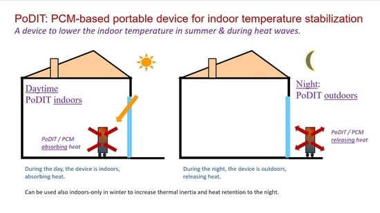
:This work introduces the concept of a new Portable Device for Indoor Temperature Stabilization (PoDIT), to be considered as a low-cost, quick and easy to implement remediation strategy when, for social, economic, or technical reasons, the improvement of the building envelope and/or the adoption of air conditioning are not possible. The main goal is to attenuate the maximum indoor temperature during summer and/or heat waves. The system, which is modular, consists of a certain mass of encaged phase change material (PCM) that stays indoors during the daytime and is transported to the outdoors (e.g., a balcony) during the night to discharge the heat accumulated during the daytime. Both natural convection and forced convection variants were considered. The results showed that, in the configurations and for the reference room and weather considered, the adopting 4 modules of the device can lead to reductions in the maximum room air temperature close to 3 °C, with natural convection. Adopting a fan to impose forced convection at the surfaces of the device can lead to temperature attenuations in excess of 4 °C, as it ensures full solid–liquid commuting and therefore optimal use of the PCM thermal storage capability.
1. Introduction
There is growing evidence that, even in developed countries, many households do not have comfortable and/or healthy indoor environmental conditions, especially in what regards to indoor temperature. The evidence comes from direct measurements [1,2], but also indirectly from an observed correlation between extreme cold and hot spots and the mortality rates [3,4,5].
For example, in Figure 1, it can be observed that the daily mortality in Portugal was actually considerably higher in some days of 2013 and 2018 than in March and April of 2020, during the first peak of the COVID-19 pandemic in Europe [6].
Theoretically, a possible solution for the problem would to deploy air conditioning to all most residential buildings, or at least to those with lower energy-efficient envelopes. However, this would present several problems:
- (i)
- Because of how electric systems are operated, in the short term the growth in electricity demand caused by AC systems would cause an increase in the operation of thermal power plants. This would increase the greenhouse gas emissions. In the medium or long term, the electricity could come from additional renewable sources, but there is competition for the use of electricity from other more urgent purposes (e.g., mobility). Likely, it would have additional costs also;
- (ii)
- (iii)
- Many households cannot afford to pay for the cost of installing the AC systems and/or the electricity that they would consume.
In this framework, it is of outmost importance to devise ways of improving the indoor temperatures, especially in summer, without requiring the installation of AC systems in every residential building.
A possibility to achieve this goal is to use the so-called “thermal flush” technique [9,10] in a way that can be easily adopted in existing buildings. This technique has traditionally made use of the storage of heat in the thermal mass of the building (thermal inertia), and then promote night ventilation to discharge the stored heat into the outdoor air. While still a valid concept, there are many cases where its effect in practice is limited by factors such as:
- (i)
- Impossibility to ventilate during the night, for safety or noise reasons;
- (ii)
- Low effectiveness of the ventilation, due to the location of the building and/or absence of wind and/or existence of obstacles surrounding the building;
- (iii)
Trying to overcome the limitations above, and to make a more effective use of the thermal flush concept, this paper presents and analyses the predicted performance of an innovative phase-change portable device that is intended to be indoors during the day, and moved outside (e.g., to a terrace, veranda or window hanger) during the night.
The idea of using phase change materials (PCMs) to assist cooling of buildings has been introduced since at least the early 2000s. The applications have been reviewed in recent papers such as those by Ostermann et al. [13], Pomianowski et al. [14], Iten et al. [15], Souayfane et al. [16], and Faraj et al. [17].
Faraj et al. [17] divide the applications between the Passive and the Active technologies. Passive ones include uses in Walls, and Trombe walls, glazing windows, floors and tiles, shutters and blinds, ceilings and roofs, sola façades, and solar chimneys Active ones include integration into evaporative and radiative cooling systems, ventilated façades, ice storage, thermally activated building structures (TABS), AC systems, and ventilated Trombe walls. No systems similar to the one proposed here were found.
Garcia [18] stresses that one of the main weaknesses of PCMs employed in passive cooling systems is that, though the peak cooling load is delayed, it still ends up discharged indoors. He then proposed an innovative concept for a dynamic building envelope with PCM, which however is likely to be difficult to be adopted at existing buildings without significant retrofit work—one of the intended key advantages of the system now proposed.
2. Device Description and Specifications
2.1. Concept and Shape
The device consists of a certain mass of PCM (phase change material) embodied in a container, with a shape that promotes an easy heat exchange with the surrounding environment (air and surfaces).
Besides ensuring mechanical robustness, the portability specification implies two main technical requirements: both weight and dimensions must both be low enough ensure that it can be carried frequently between the indoors and the outdoors (and vice-versa) by any person who is healthy but not necessarily athletic.
For this proof-of-concept study, a mass limit value of around 20 kg per device was considered. Given the mass specifications, the selection of PCM device shell (box) material led to the choice of a lightweight but resistant material with a high thermal conductivity: an aluminum sheet with a thickness of 2 mm was selected as the box material.
Regarding dimensions, the maximization of surface area was used as a criterion, thus adopting a geometry of thin quadrangular plates. The dimensions adopted in the PCM envelope box took into account the maximization of the surface area, but also the volumetric expansion verified in the phase change materials considered in this study. Thin plates were adopted to improve the spread of heat inside the devices.
Figure 2 presents a schematic representation with the overall dimensions of the PCM device. The shape may nevertheless be the object of optimization at a later stage of product development. It is also possible to consider the deployment of several independent modules into room.
2.2. PCM Characteristics
Suitable PCM were searched among those that are commercially available as technically developed/mature products. The key criteria was the phase change temperature. For an initial scenario under “normal summer weather”, a PCM with phase change at 24 °C was selected [19], which therefore implies that the device will work to “try” to limit the indoor temperature to 24 °C, as is somewhat in line with conventional HVAC comfort requirements. An alternative PCM with a transition temperature of 29 °C was also considered [19], for sensitivity assessment (Table 1).
For the scenario under heat wave conditions, it proved that the 24 °C transition temperature was too low (among other things this temperature is too low for an efficient discharge outdoors during the night), and the C19H40 Nonadecane parafine, which has a transition temperature of 32 °C, was considered instead [20]. This type of material is widely used in buildings thermal applications and has advantageous properties in the context of the proposed application: congruent melting, good nucleating properties, chemically stable, non-toxic, non-corrosive, and metal casing compatibility [21]. The 32 °C transition temperature is high when compared with the conventional HVAC setpoints around 24–25 °C, but it is nevertheless representative of the more extreme conditions that may happen during heat waves. In these cases, the device will work to “try” to limit the indoor temperature to 32 °C, which despite being high in terms of comfort avoids the most dangerous temperatures regarding health. The PCM with a transition temperature of 29 °C was also considered, for sensitivity assessment.
A significant limitation of the phase change materials is their low thermal conductivity, which slows their ability to store and release thermal energy in time periods compatible with the requirements, thus decreasing the overall system performance.
A technique to enhance the thermal conductivity of phase change materials was proposed by X. Py [22] where the PCM is embedded inside a porous graphite matrix. The main advantage of this new composite material (PCM and graphite) is the increase in heat conductivity without much reduction in energy storage and the decrease of volume change in paraffins [23].
A parametric study showed that a thermal conductivity greater than 5 Wm−1K−1 did not significantly decrease PCM liquefaction or solidification time, representing the best compromise between increased thermal conductivity and decreased thermal storage capacity [24]. This thermal conductivity can be achieved with a graphite volumetric fraction of only 3%.
Table 1 summarizes the key physical characteristics of the PCM materials, already considering the effect of doping with graphite, calculated according to the correlation by Py et al. [22]. Table 2 shows the resulting key physical characteristics of the device, considering both the casing and the PCM.
3. Test Room and Study Scenarios
In order to assess the expectable order of magnitude of the effect of the device in the indoor temperature, a reference room realistically representative of a room in a real building was considered. Figure 3 shows a schematic representation of the reference room with the respective dimensions. The reference compartment is a small room with 14 m2 of floor area and 2.7 m in height, with two exterior walls facing south and east, both with a 2 m2 window, a horizontal roof terrace, two interior walls and interior floor. There is also a 2 m2 door in the interior wall (D). It is considered that the adjacent rooms have similar thermal behavior. These characteristics, especially those related to the solar orientation and aperture, imply that the room is prone to some overheating—therefore among those that are the primary target of the system being developed.
Regarding the building materials, two variants were considered: one using high-density materials such as concrete and bricks (high thermal inertia variant), and another using low density materials such as plasterboard (low thermal inertia variant). The high thermal inertia solution was based in typical Portuguese single-family buildings, with ceramic bricks and expanded polystyrene EPS insulation on the outside. The low thermal inertia solution uses plasterboard at the interior walls, and the EPS isolation is located on the inside of the structuring elements. Table 3 shows the details the constructions, while Table 4 shows the properties of the materials.
4. Heat Transfer Modelling
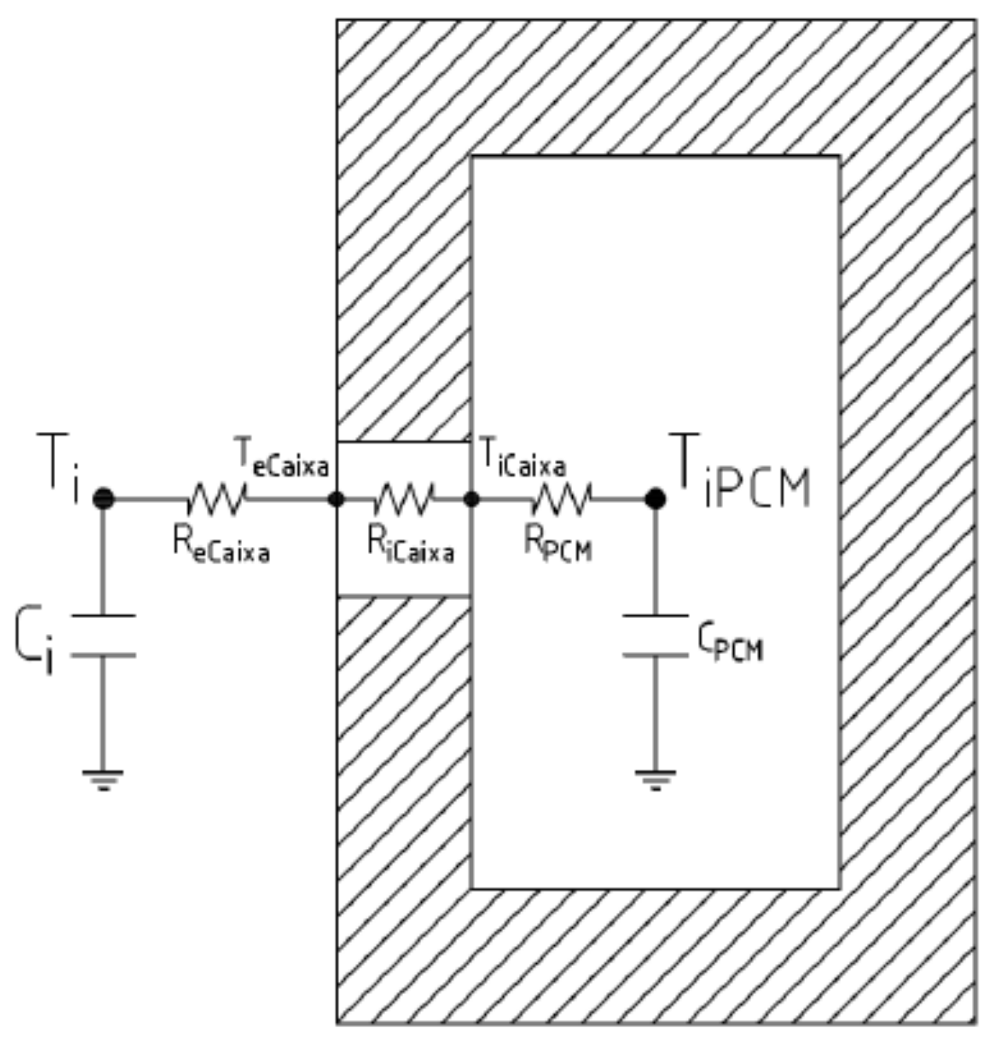
The modeling approach followed the classic analogy of thermal systems with electrical Resistance-Capacitance (RC) circuits applied to buildings [26]. This approach has been used with very good results as long as the discretization of the system is adequate [27,28,29].
Figure 4 shows the RC circuit representing the heat transfer inside the device and between the device and the room air (Ti).
Besides the device itself, it is important to model the room and the interaction between the device and the surrounding environment (room during the day, and the outdoor environment during the night). Figure 5 shows the model representation for this integrated room + device system. The model was implemented by own coding in the MATLAB software (MATLAB. 9.7. The MathWorks Inc.; Natick, MA, USA, 2018.)
For this work two weather conditions were considered: Typical Summer and Heat Wave. For the Typical Summer weather profile, hourly climatic data from the database of Portugal’s National Energy and Geology Laboratory (LNEG) was used. The reference location of Torre de Moncorvo, inner Portugal, was selected as representative of a location prone to overheating–though not the warmest within the country. It is characterized by a summer/cooling season lasting 2.7 months, typical maximum temperatures above 37 °C, and high incidence of solar radiation.
This weather profile adopted is show in Figure 6, with a maximum temperature of 37.8 °C, and a minimum of 15.9 °C. A sequence of similar days was considered.
The Heat Wave weather profile represents a hypothetical extreme scenario during heat waves and characterized by very high maximum temperatures and tropical nights, where the minimum temperature does not drop below 20 °C. This weather profile was based in historical record temperatures observed in Portugal and was developed considering a maximum temperature of 45 °C and a minimum of 25 °C. The hourly profile was built according to a procedure for generating 24 h temperature data sequences recommended by ASHRAE, adopting the normalized daily temperature profile as fractions of the daily temperature range [29]. The solar radiation data for the Heat Wave weather was kept the same as for the normal summer weather, which was already quite high as can be seen in Figure 6.
5. Results
5.1. Results for Normal Summer Conditions and Natural Convection
The thermal behavior of the device and its impact upon the indoor air temperature was initially characterized for the normal summer condition, and considering natural convection at the surfaces of the device (both when placed indoors, during the day, and when placed outdoors during the night).
Figure 7 and Figure 8 show the indoor air temperature of the room, for the low and high room inertia scenarios, considering none, one or four Portable Device for Indoor Temperature Stabilization (PoDIT) modules. The peak temperature attenuation observed in the low inertia room is about 0.8 °C with one PoDIT module (1 plate), and about 2.7 °C if four modules (4 plates) are used. For the high inertia room, the observed attenuation is about 0.5 °C with one PoDIT module (1 plate), and about 2 °C with four modules (4 plates).
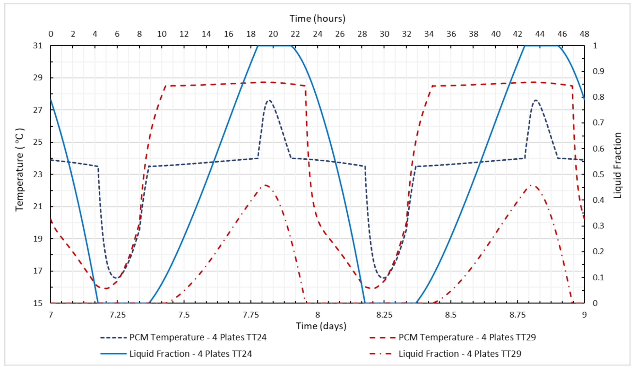
Figure 9 shows the temperature of the PCM and its liquid fraction in the same period of Figure 7, for low thermal inertia case. It can be seen that the PCM never becomes fully liquid. Thus, it does not make use of its maximum thermal storage capability, which hinders its performance/contribution to indoor temperature attenuation.
5.2. Results for Normal Summer Conditions and Forced Convection
In order to overcome the shortcoming illustrated in Figure 9 (PCM never becoming fully liquid), it was decided to consider a design variant with a fan blowing air at 5 m/s through the external surfaces of the device, triggering forced convection and thus intensifying the heat transfer to and from the PCM. Figure 10 shows the results of the PCM and its liquid fraction with these new conditions. They clearly show that in this circumstance the PCM transition temperature of 24 °C does become fully liquid, thus making full use of its thermal storage capability. The PCM with a transition temperature of 29 °C improves considerably compared to Figure 9, but still does not become fully liquid.
Figure 11 and Figure 12 show the indoor temperatures for 2 days in different building inertia and device alternatives, for the case with forced convection at the place surfaces. With one PoDIT module (1 plate), the observed peak temperature attenuation is about 1.1 °C for the low inertia room, and about 0.9 °C for the high inertia room. If four modules are used, then the peak temperature attenuation becomes slightly above 4 °C in the low thermal inertia building and close to 3 °C in the high thermal inertia room. Table 5 summarizes the impact of the device in the indoor temperature, showing reductions vs the “no device case” for the maximum room air temperature and for the room air temperature at 2 AM.
5.3. Heat Wave Conditions
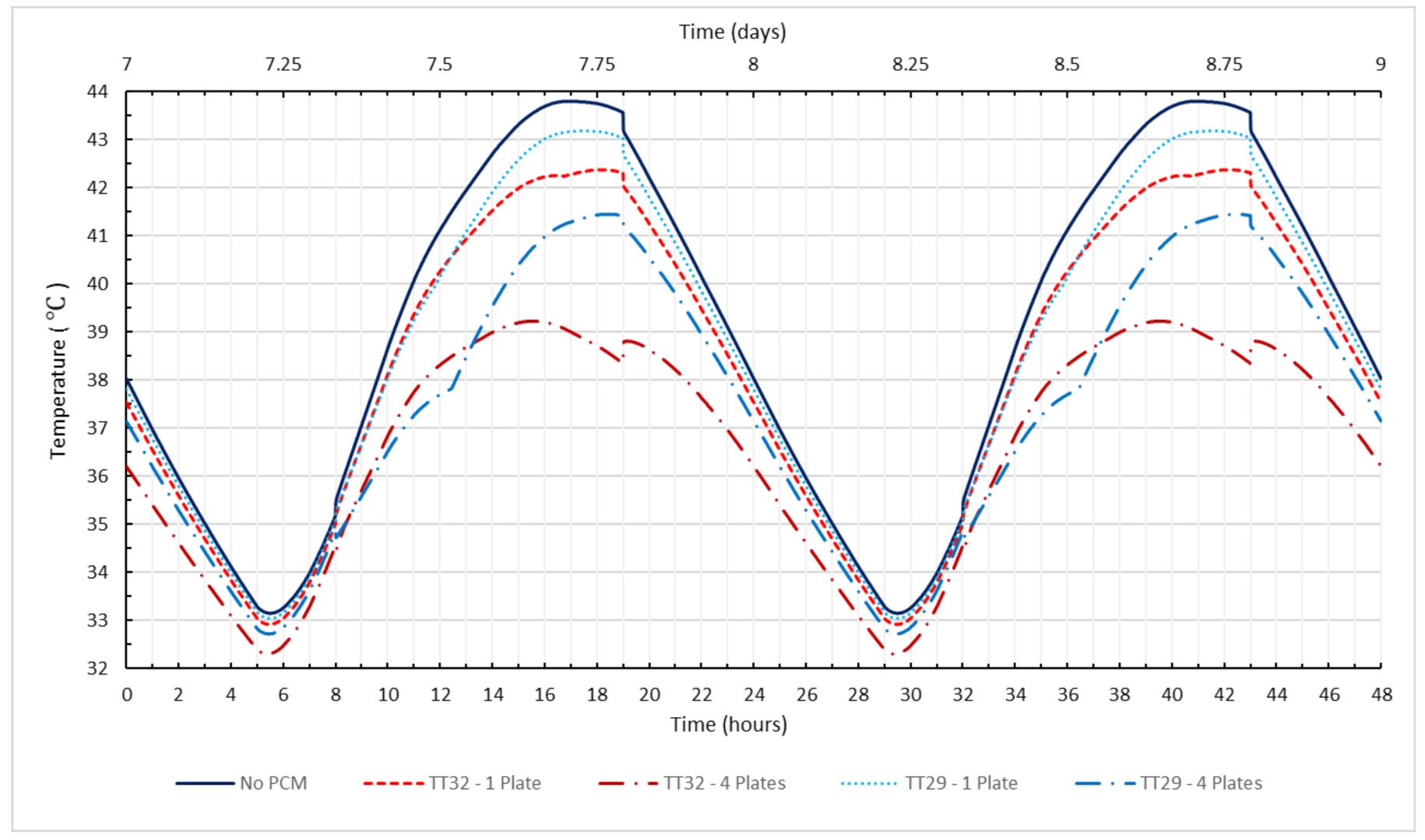
Figure 13 and Figure 14 show the indoor temperatures during the heat wave conditions (as defined in Figure 6/Section 4), for the cases of natural or forced convection upon the system device respectively. Table 6 summarizes the impact of the PoDIT device in terms of reduction on the maximum indoor temperature. It can be seen that, for the reference room studied, the device with the TT32 PCM enables reductions in the maximum indoor temperature between 1.8 and 2.9 °C for the high thermal inertia room, and between 2.9 and 4.6 °C for the low inertia room. The PCM with a transition temperature of 29 °C yields lower temperature attenuations.
These results show that, at least in the harsh conditions considered for this study, the PoDIT device cannot be seen as a general substitute of air conditioning—the indoor temperatures are too high under any of the scenarios. It can nevertheless provide a valuable contribution for the attenuation of discomfort and health consequences.
6. Conclusions
This work introduces the concept of a new Portable Device for Indoor Temperature Stabilization (PoDIT), to be considered as a low-cost, quick and easy to implement remediation strategy when, for social, economic, or technical reasons, the improvement of the building envelope and/or the adoption of air conditioning are not possible.
The system, which is modular, consists of a certain mass of engaged PCM that stays indoors during the daytime and is transported to the outdoors (e.g., a balcony) during the night to discharge the heat accumulated during the daytime. Both natural convection and forced convection (requiring a fan, in this case) variants were considered.
The results showed that, in the configurations and for the reference room and weather considered, adopting 4 modules of the device can lead to reductions in the maximum room air temperature close to 3 °C with natural convection, and more than 4 °C if a fan imposing forced convection is adopted. Adopting a fan proved important to ensure full solid–liquid commuting and therefore optimal use of the PCM thermal storage capability.
For the room studied, which has high solar aperture, and in the inner Iberian peninsula climate considered, the reduction achieved alone is not sufficient to ensure thermal comfort, as indoor air temperatures in excess of 30 °C were still obtained. Nevertheless, under stress conditions as is the case of heat waves, any attenuation of 3 or 4 °C may be important to avoid critical consequences in terms of health. Furthermore, the reference room considered has very high solar aperture.
Among the limitations of the system are the need for the existence for a terrace or balcony close to the room so that it can be placed outdoors during the night and the occupation of internal space when placed indoors.
As for future work, there is room for studying alternative/more complex system configurations, both with forced and with natural convection options, that could eventually lead to improved performance. Experimental measurements may assist a definitive validation of the models too and/or assist exploring alternative configurations. It could also address the performance of such system in other combinations of room and climate and room characteristics—e.g., to see how it operates in central and northern European cases, for example, where it may have the potential to avoid the usage of air conditioning. It would also be of interest to assess its potential use in some small commercial stores that have no air-conditioning, as well as to assess potential contribution to retain solar gains in winter. A more complete assessment of impact of the impact upon comfort, considering radiant and operative temperatures, may also be of interest at some point.
Author Contributions
Conceptualization: V.L.; methodology, V.L and R.T.; modelling: R.T. and V.L.; programming and simulations: R.T.; writing—original draft preparation, V.L. and R.T. All authors have read and agreed to the published version of the manuscript.
Funding
This research received no external funding.
Acknowledgments
The authors thank the valuable contribution of Helena Corvacho, from the Department of Civil Engineering at FEUP, who kindly commented options for making the reference room realistic from a constructions perspective.
Conflicts of Interest
The authors declare no conflict of interest.
List of Acronyms and Abbreviations
| ASHRAE | American society of heating refrigerating and air conditioning |
| EPS | Expanded Polystyrene |
| GHG | Greenhouse effect gases |
| HVAC | –Heating, Ventilation and Air Conditioning |
| PCM | Phase Change Material |
| PoDIT | Portable Device for Indoor Temperature stabilization |
References
- Ostermana, E.; Tyagib, V.V.; Butalaa, V.; Rahimb, N.A.; Stritih, U. Review of PCM based cooling technologies for buildings. Energy Build. 2012, 49, 37–49. [Google Scholar] [CrossRef]
- Pomianowskia, M.; Heiselberga, P.; Zhangb, Y. Review of thermal energy storage technologies based on PCM application in buildings. Energy Build. 2013, 67, 56–69. [Google Scholar] [CrossRef]
- Iten, M.; Liu, S.; Shukla, A. A review on the air-PCM-TES application for free cooling and heating in the buildings. Renew. Sustain. Energy Rev. 2016, 61, 175–186. [Google Scholar] [CrossRef]
- Souayfanea, F.; Fardouna, F.; Biwoleb, P.-H. Phase change materials (PCM) for cooling applications in buildings: A review. Energy Build. 2016, 129, 396–431. [Google Scholar] [CrossRef]
- Faraj, K.; Khaled, M.; Faraj, J.; Hachem, F.; Castelain, C. Phase change material thermal energy storage systems for cooling applications in buildings: A review. Renew. Sustain. Energy Rev. 2020, 119, 109579. [Google Scholar] [CrossRef]
- de Gracia, A. Dynamic building envelope with PCM for cooling purposes—Proof of concept. Appl. Energy 2019, 235, 1245–1253. [Google Scholar] [CrossRef]
- Santamouris, M.; Alevizos, S.M.; Aslanoglou, L.; Mantzios, D.; Milonas, P.; Sarelli, I.; Karatasou, S.; Cartalis, K.; Paravantis, J.A. Freezing the poor—Indoor environmental quality in low and very low income households during the winter period in Athens. Energy Build. 2014, 70, 61–70. [Google Scholar] [CrossRef]
- Magalhães, S.M.C.; Leal, V.M.S.; Horta, I.M. Predicting and characterizing indoor temperatures in residential buildings: Results from a monitoring campaign in Northern Portugal. Energy Build. 2016, 119, 293–308. [Google Scholar] [CrossRef]
- Royé, D.; Codesido, R.; Tobías, A.; Taracido, M. Heat wave intensity and daily mortality in four of the largest cities of Spain. Environ. Res. 2020, 182, 109027. [Google Scholar] [CrossRef]
- Nori-Sarma, A.; Anderson, G.B.; Rajiva, A.; ShahAzhar, G.; Gupta, P.; Pednekar, M.S.; Son, J.; Peng, R.D.; Bell, M.L. The impact of heat waves on mortality in Northwest India. Environ. Res. 2019, 176, 108546. [Google Scholar] [CrossRef]
- Ma, W.; Zeng, W.; Zhou, M.; Wang, L.; Rutherford, S.; Lin, H.; Liu, T.; Zhang, Y.; Xiao, J.; Zhang, Y.; et al. The short-term effect of heat waves on mortality and its modifiers in China: An analysis from 66 communities. Environ. Int. 2015, 75, 103–109. [Google Scholar] [CrossRef] [PubMed]
- DGS—Portuguese Directorate General for Health. eVM Online Monitoring of the Mortality in Portugal. Available online: https://evm.min-saude.pt (accessed on 30 April 2020).
- Rupp, R.F.; Kim, J.; de Dear, R.; Ghisi, E. Associations of occupant demographics, thermal history and obesity variables with their thermal comfort in air-conditioned and mixed-mode ventilation office buildings. Build. Environ. 2018, 135, 1–9. [Google Scholar] [CrossRef]
- Gupta, S.; Khare, M.; Goyal, R. Sick building syndrome—A case study in a multistory centrally air-conditioned building in the Delhi City. Build. Environ. 2007, 42, 2797–2809. [Google Scholar] [CrossRef]
- Bhamare, D.K.; Rathod, M.K.; Banerjee, J. Passive cooling techniques for building and their applicability in different climatic zones—The state of art. Energy Build. 2019, 198, 467–490. [Google Scholar] [CrossRef]
- Solgi, E.; Kari, B.M.; Fayaz, R.; Taheri, H. The impact of phase change materials assisted night purge ventilation on the indoor thermal conditions of office buildings in hot-arid climates. Energy Build. 2017, 150, 488–497. [Google Scholar] [CrossRef] [Green Version]
- Paulo, M.D.; Veiga, M.d.R.; de Brito, J. Gypsum coatings in ancient buildings. Constr. Build. Mater. 2007, 21, 126–131. [Google Scholar] [CrossRef]
- Sabapathy, K.A.; Gedupudi, S. On the influence of concrete-straw-plaster envelope thermal mass on the cooling and heating loads for different climatic zones of India. J. Clean. Prod. 2020, 276, 123117. [Google Scholar] [CrossRef]
- Puretemp Website. Available online: http://www.puretemp.com/stories/puretemp-technical-data-sheets (accessed on 14 October 2020).
- Sharma, A.; Tyagi, V.V.; Chen, C.R.; Buddhi, D. Review on thermal energy storage with phase change materials and applications. Renew. Sustain. Energy Rev. 2009, 13, 318–345. [Google Scholar] [CrossRef]
- Alva, G.; Lin, Y.; Fang, G. An overview of thermal energy storage systems. Energy 2018, 144, 341–378. [Google Scholar] [CrossRef]
- Py, X.; Olives, R.; Mauran, S. Paraffin/porous-graphite-matrix composite as a high and constant power thermal storage material. Int. J. Heat Mass Transf. 2001, 44, 2727–2737. [Google Scholar] [CrossRef]
- Marín, J.M.; Zalba, B.; Cabeza, L.F.; Mehling, H. Improvement of a thermal energy storage using plates with paraffin-graphite composite. Int. J. Heat Mass Transf. 2005, 48, 2561–2570. [Google Scholar] [CrossRef]
- dos Santos Teixeira, R.M. Avaliação e Pré-Dimesionamento de um Dispositivo de Mudança de Fase para Mitigação de Ondas de calor. Master’s Thesis, University of Porto, Porto, Portugal, 2019. [Google Scholar]
- Coelho, P. Tabelas de Termodinâmica, 4th ed.; Lidel: Lisbon, Portugal, 2017. (In Portuguese) [Google Scholar]
- Sonderegger, R.C. Dynamic Models of House Heating Based on Equivalent Thermal Parameters. Ph.D. Thesis, Princeton University, Princeton, NJ, USA, 1978. [Google Scholar]
- Bacher, P.; Madsen, H. Identifying suitable models for the heat dynamics of buildings. Energy Build. 2011, 43, 1511–1522. [Google Scholar] [CrossRef] [Green Version]
- Bagheri, A. Development of Simplified RC Models with Physically Deducible Parameters Using the Time-Constant Concept for the Calculation of the Heating Load Demand in Single Detached Dwellings and Districts. Ph.D. Thesis, University of Mons, Mons, Belgium, 2019. [Google Scholar]
- America Society of Heating, Refrigeration and Air Conditioing Engineers. ASHRAE Fundamentals (2007), 2009 ASHRAE Handbook—Fundamentals (SI Edition). Atlanta, USA. Available online: https://app.knovel.com/web/toc.v/cid:kpASHRAE37/viewerType:toc/ (accessed on 12 November 2020).
Figure 1.
Daily mortality in Portugal from 2009 to April 2020 [6].
Figure 1.
Daily mortality in Portugal from 2009 to April 2020 [6].

Figure 2.
Schematic representation of the device for this proof-of-concept study (1 module).

Figure 3.
Schematic representation of the reference room for assessment of the impact upon indoor temperature.
Figure 3.
Schematic representation of the reference room for assessment of the impact upon indoor temperature.

Figure 4.
RC circuit representing the heat transfer inside the device and between the device and the room air. Ti represents the room air temperature; TiPCM is the PCM temperature [24].
Figure 4.
RC circuit representing the heat transfer inside the device and between the device and the room air. Ti represents the room air temperature; TiPCM is the PCM temperature [24].

Figure 5.
RC model of the room + Portable Device for Indoor Temperature Stabilization (PoDIT) device [24]. Qsi represent solar incidence on the floor and external walls, QGI the internal gains and QR the heat gains or losses due to ventilation/air renovation.
Figure 5.
RC model of the room + Portable Device for Indoor Temperature Stabilization (PoDIT) device [24]. Qsi represent solar incidence on the floor and external walls, QGI the internal gains and QR the heat gains or losses due to ventilation/air renovation.

Figure 6.
Temperature and solar radiation (Horizontal, South, and East) hourly profiles considered in the typical summer and in the heat wave conditions/scenarios.
Figure 6.
Temperature and solar radiation (Horizontal, South, and East) hourly profiles considered in the typical summer and in the heat wave conditions/scenarios.

Figure 7.
Indoor temperatures for the room with low thermal inertia, for the cases of no PCM, PCM with transition/melting temperature of 24 °C, and transition/melting temperature at 29 °C.
Figure 7.
Indoor temperatures for the room with low thermal inertia, for the cases of no PCM, PCM with transition/melting temperature of 24 °C, and transition/melting temperature at 29 °C.

Figure 8.
Indoor temperatures for the room with high thermal inertia, for the cases of no PCM, PCM with transition/melting temperature of 24 °C, and transition/melting temperature at 29 °C.
Figure 8.
Indoor temperatures for the room with high thermal inertia, for the cases of no PCM, PCM with transition/melting temperature of 24 °C, and transition/melting temperature at 29 °C.

Figure 9.
PCM temperature and liquid fraction for the room in low inertia configuration, during normal summer conditions, with natural convection.
Figure 9.
PCM temperature and liquid fraction for the room in low inertia configuration, during normal summer conditions, with natural convection.

Figure 10.
PCM temperature and liquid fraction for the room in low inertia configuration, during normal summer conditions, with forced convection.
Figure 10.
PCM temperature and liquid fraction for the room in low inertia configuration, during normal summer conditions, with forced convection.

Figure 11.
Indoor temperatures for the low inertia room and normal climate, with forced convection at the place surfaces.
Figure 11.
Indoor temperatures for the low inertia room and normal climate, with forced convection at the place surfaces.

Figure 12.
Indoor temperatures for the high inertia room and normal climate, with forced convection at the place surfaces.
Figure 12.
Indoor temperatures for the high inertia room and normal climate, with forced convection at the place surfaces.

Figure 13.
Indoor temperatures, for the low inertia case with natural convection at the place surfaces, under heat wave conditions.
Figure 13.
Indoor temperatures, for the low inertia case with natural convection at the place surfaces, under heat wave conditions.

Figure 14.
Indoor temperatures, for the low inertia case with forced convection at the place surfaces.
Figure 14.
Indoor temperatures, for the low inertia case with forced convection at the place surfaces.


Table 1.
Key physical characteristics of the three composite materials considered, computed according to the method proposed by Py et al. [22].
Table 1.
Key physical characteristics of the three composite materials considered, computed according to the method proposed by Py et al. [22].
| PCM—Graphite Composite | Paraffine C19H40 | PureTemp 24 | PureTemp 29 | |
|---|---|---|---|---|
| Graphite volume | (---) | 3% | 3% | 3% |
| Volumetric mass of the matrix | (kg m−3) | 64.6 | 64.6 | 64.6 |
| Phase change | (°C) | 32 | 24 | 29 |
| Fusion latent heat | (kJ kg−1) | 204 | 171 | 187 |
| Specific heat in solid phase | (J kg−1 K−1) | 1713 | 2696 | 1693 |
| Specific heat in liquid phase | (J kg−1 K−1) | 2081 | 2873 | 1851 |
| Volumetric mass in liquid phase | (kg m−3) | 811.5 | 822.2 | 890.2 |
| Volumetric mass in solid phase | 950.4 | 987.3 | 977.2 | |
| Heat conductivity of the composite in liquid phase | (Wm−1 K−1) | 5 | 5 | 5 |
| Heat conductivity of the composite in solid phase | (Wm−1 K−1) | 5 | 5 | 5 |
Table 2.
Key physical characteristics of the device, considering the casing and the phase change material (PCM) composite.
Table 2.
Key physical characteristics of the device, considering the casing and the phase change material (PCM) composite.
| Height | 0.65 | m |
| Length | 0.65 | m |
| Width | 0.05 | m |
| Box Thickness | 0.002 | m |
| Heat Transfer Area | 0.845 | m2 |
| Aluminum Box Mass | 5.2 | kg |
| PCM Composite Mass | 15.6 | kg |
| Total Mass (Box + PCM) | 20.8 | kg |
| Box Material | Aluminum Plate 1050A H24 [25] | |
| Volumetric Mass Density | 2700 | kg m−3 |
| Specific Heat | 900 | J kg−1 K−1 |
| Thermal Conductivity | 229 | Wm−1 K−1 |
Table 3.
Room constructions considered in the High and Low thermal inertia variants.
| Hight Thermal Inertia | Low Thermal Inertia | |||
|---|---|---|---|---|
| Element | Material | Thickness (m) | Material | Thickness (m) |
| Exterior Wall A, B | Interior Plaster | 0.02 | Interior Plaster | 0.02 |
| Ceramic Brick | 0.15 | EPS Insulation | 0.03 | |
| EPS Insulation | 0.03 | Ceramic Brick | 0.15 | |
| Exterior Plaster | 0.02 | Exterior Plaster | 0.02 | |
| Interior Wall C, D | Plaster | 0.02 | Plasterboard | 0.018 |
| Ceramic Brick | 0.11 | Air Gap | 0.12 | |
| Plaster | 0.02 | Plasterboard | 0.018 | |
| Roof E | Exterior Protection (Inert) | 0.05 | Exterior Protection (Inert) | 0.03 |
| EPS Insulation | 0.03 | Shape Layer | 0.04 | |
| Shape Layer | 0.05 | Light Slab | 0.15 | |
| Light Slab | 0.15 | EPS Insulation | 0.03 | |
| Interior Plaster | 0.02 | Interior Plaster | 0.02 | |
| Floor F | Wood floor | 0.01 | Wood floor | 0.01 |
| Screed | 0.04 | EPS Insulation | 0.03 | |
| Light Slab | 0.15 | Screed | 0.04 | |
| Plaster | 0.02 | Light Slab | 0.15 | |
| Plaster | 0.02 | |||
Table 4.
Materials properties considered in the room constructions.
| Material | Thermal Conductivity (Wm−1 K−1) | (kg m−3) | cP (J kg−1 K−1) |
|---|---|---|---|
| Plaster | 1.3 | 1900 | 837 |
| Holed Ceramic Brick 15 | 0.38 | 800 | 936 |
| Holed Ceramic Brick 11 | 0.41 | 900 | 936 |
| Lightweight Slab (with form layer) | 0.85 | 1320 | 965 |
| Cavernous Concrete | 0.25 | 700 | 1000 |
| Inert | 2 | 2000 | 500 |
| Screed | 1.3 | 1800 | 880 |
| Plasterboard | 0.25 | 750 | 1000 |
| Wood Floor | 0.17 | 750 | 2400 |
Table 5.
Impact of the PoDIT system upon indoor air temperature of the reference room, for several configurations and conditions, considering the reference normal weather.
Table 5.
Impact of the PoDIT system upon indoor air temperature of the reference room, for several configurations and conditions, considering the reference normal weather.
| Natural Convection | Forced Convection | ||||||||
|---|---|---|---|---|---|---|---|---|---|
| TT24 | TT29 | TT24 | TT29 | ||||||
(°C) | (°C) | (°C) | (°C) | ||||||
| Low Inertia room | No PCM | 35.1 | -- | 35.1 | -- | 35.1 | -- | 35.1 | -- |
| 1 PCM Plate | 34.3 | 0.8 | 34.6 | 0.4 | 33.8 | 1.2 | 34.3 | 0.8 | |
| 4 PCM Plates | 32.4 | 2.6 | 33.7 | 1.4 | 30.8 | 4.3 | 32.8 | 2.3 | |
| High Inertia room | No PCM | 31.9 | -- | 31.9 | -- | 31.9 | -- | 31.9 | -- |
| 1 PCM Plate | 31.5 | 0.5 | 31.8 | 0.2 | 31.1 | 0.9 | 31.6 | 0.4 | |
| 4 PCM Plates | 30.3 | 1.6 | 31.3 | 0.7 | 29.2 | 2.7 | 30.8 | 1.1 | |
Table 6.
Impact of the PoDIT system upon indoor air temperature of the reference room, for several configurations and conditions, considering the weather under heat wave conditions.
Table 6.
Impact of the PoDIT system upon indoor air temperature of the reference room, for several configurations and conditions, considering the weather under heat wave conditions.
| Natural Convection | Forced Convection | ||||||||
|---|---|---|---|---|---|---|---|---|---|
| TT24 | TT29 | TT24 | TT29 | ||||||
(°C) | (°C) | (°C) | (°C) | ||||||
| Low Inertia room | No PCM | 43.8 | – | 43.8 | – | 43.8 | – | 43.8 | – |
| 1 PCM Plate | 42.9 | 0.9 | 43.2 | 0.6 | 42.4 | 1.4 | 43.2 | 0.6 | |
| 4 PCM Plates | 40.9 | 2.9 | 41.5 | 2.3 | 39.2 | 4.6 | 41.5 | 2.3 | |
| High Inertia room | No PCM | 40.6 | – | 40.6 | – | 40.6 | – | 40.6 | – |
| 1 PCM Plate | 40.1 | 0.5 | 40.2 | 0.4 | 39.7 | 0.9 | 40.2 | 0.4 | |
| 4 PCM Plates | 38.9 | 1.8 | 39.0 | 1.7 | 37.7 | 2.9 | 39.0 | 1.6 | |
Publisher’s Note: MDPI stays neutral with regard to jurisdictional claims in published maps and institutional affiliations. |
© 2020 by the authors. Licensee MDPI, Basel, Switzerland. This article is an open access article distributed under the terms and conditions of the Creative Commons Attribution (CC BY) license (http://creativecommons.org/licenses/by/4.0/).
Share and Cite
MDPI and ACS Style
Leal, V.; Teixeira, R. PoDIT: Portable Device for Indoor Temperature Stabilization: Concept and Theoretical Performance Assessment. Energies 2020, 13, 5982. https://0-doi-org.brum.beds.ac.uk/10.3390/en13225982
AMA Style
Leal V, Teixeira R. PoDIT: Portable Device for Indoor Temperature Stabilization: Concept and Theoretical Performance Assessment. Energies. 2020; 13(22):5982. https://0-doi-org.brum.beds.ac.uk/10.3390/en13225982
Chicago/Turabian StyleLeal, Vítor, and Raul Teixeira. 2020. "PoDIT: Portable Device for Indoor Temperature Stabilization: Concept and Theoretical Performance Assessment" Energies 13, no. 22: 5982. https://0-doi-org.brum.beds.ac.uk/10.3390/en13225982
Note that from the first issue of 2016, this journal uses article numbers instead of page numbers. See further details here.