Article

Porosity and Water Saturation Estimation for Shale Reservoirs: An Example from Goldwyer Formation Shale, Canning Basin, Western Australia

Department of Petroleum Engineering, Western Australia School of Mines: Minerals, Energy and Chemical Engineering, Curtin University, 26 Dick Perry Avenue, Kensington, WA 6151, Australia
*
Author to whom correspondence should be addressed.
Submission received: 12 November 2020 / Revised: 26 November 2020 / Accepted: 27 November 2020 / Published: 29 November 2020
(This article belongs to the Special Issue Development of Unconventional Reservoirs 2020)

Abstract

:
Porosity and water saturation are the most critical and fundamental parameters for accurate estimation of gas content in the shale reservoirs. However, their determination is very challenging due to the direct influence of kerogen and clay content on the logging tools. The porosity and water saturation over or underestimate the reserves if the corrections for kerogen and clay content are not applied. Moreover, it is very difficult to determine the formation water resistivity (Rw) and Archie parameters for shale reservoirs. In this study, the current equations for porosity and water saturation are modified based on kerogen and clay content calibrations. The porosity in shale is composed of kerogen and matrix porosities. The kerogen response for the density porosity log is calibrated based on core-based derived kerogen volume. The kerogen porosity is computed by a mass-balance relation between the original total organic carbon (TOCo) and kerogen maturity derived by the percentage of convertible organic carbon (Cc) and the transformation ratio (TR). Whereas, the water saturation is determined by applying kerogen and shale volume corrections on the Rt. The modified Archie equation is derived to compute the water saturation of the shale reservoir. This equation is independent of Rw and Archie parameters. The introduced porosity and water saturation equations are successfully applied for the Ordovician Goldwyer formation shale from Canning Basin, Western Australia. The results indicate that based on the proposed equations, the total porosity ranges from 5% to 10% and the water saturation ranges from 35% to 80%. Whereas, the porosity and water saturation were overestimated by the conventional equations. The results were well-correlated with the core-based porosity and water saturation. Moreover, it is also revealed that the porosity and water saturation of Goldwyer Formation shale are subjected to the specific rock type with heterogeneity in total organic carbon total clay contents. The introduced porosity and water saturation can be helpful for accurate reserve estimations for shale reservoirs.

Graphical Abstract

1. Introduction

The organic-rich shale reservoirs have gained increasing attention in the last decades due to the depletion of conventional reservoirs [1,2]. For reliable volumetric calculation of the reserve, the porosity and water saturation are the most critical parameters to estimate [3,4,5,6]. The shale reservoirs contain free and adsorbed gases. The free gas associates within the pore spaces whereas the adsorbed gas is usually linked with the clay minerals and organic matter [2,4,7,8,9,10]. However, the complex pore system and organic matter together with inorganic mineral constituents affect the well logging tool responses needing to take them into account during petrophysical evaluation. Previous studies demonstrate that the porosity can be overestimated by using empirical equations without applying kerogen corrections. Therefore, the conventional approaches for porosity estimation are not feasible for organic-rich shale reservoirs. Many authors selected petrophysical models based on wireline logs to generate a set of simultaneous equations to estimate the kerogen content, mineral volume, and pore volume [7,11,12,13]. The introduced methods are most suitable for composition computation; however, it is hard to accurately determine all the required coefficients. Similarly, few authors standardised the well logs by multiplying the log data with defined coefficients to match the results with the core-derived porosity [12]. However, such equations were limited to a specific area and data set due to heterogeneity of shale in terms of thermal maturity, mineral composition, and organic matter content. Moreover, the organic-rich shales consist of the organic as well as matrix porosities [5,10,14,15,16]. In this study, the porosity for the shale reservoir is estimated by using a kerogen corrected density log, and the kerogen porosity is calculated by using a mass balance method based on original total organic carbon (TOCo) and kerogen maturity. The core-based total organic carbon (TOC) and porosity were used to validate the results.
Similarly, the accurate estimation of water saturation also plays a key role in economic evaluations of shale reservoirs. However, the investigations of the water saturation determination methods did not get much attention in the literature. Already available water saturation equations, e.g., Archie and Simandoux work better for conventional reservoirs (e.g., sandstone and shaly sands) [17,18]. However, the accurate determination of the unknown parameters such as formation water resistivity (Rw), cementation exponent (m), and saturation exponent (n) is very challenging for shale reservoirs [2,4,19,20,21]. The shale reservoir is a mixture of inorganic material (e.g., clays and detrital grains), kerogen, clay bound water, free and capillary held water, free and adsorbed gas [2,4]. However, the resistivity tool measures a reflection of constituent minerals and fluids of shales. Therefore, it is very critical to correct the resistivity log for shale and kerogen effects. In this research, a water saturation equation independent of water resistivity and Archie’s parameters is introduced. Based on core derived water saturation validation, this equation worked very well as compared to other equations. However, it is always hard to take and interpret pressurised core samples from shale reservoirs. Therefore, sometimes it is impractical to measure water saturation through core samples in shale.
A case study from organic-rich Ordivician Goldwyer Formation (Goldwyer-III shale unit), Canning Basin, Western Australia is presented to verify both techniques for porosity and water saturation estimations. The Goldwyer Formation of Lower to Middle Ordovician age has an average thickness of almost 400 m, whereas, it’s the thickest encounter (740 m) is recorded in Blackstone 1, a Lennard Shelf Sub-basin well. The Goldwyer shale is deposited in an open marine setting [22] having thin laminations of quartz silt and carbonates bands with alternating black shale layers. The mineral composition of Goldwyer shale includes quartz, carbonates, clay minerals, and pyrite [14]. The illite is a more abundant clay mineral in this shale. The Goldwyer shale is thermally mature having kerogen types-II and III and the total organic carbon content (TOC) varies from 0.35 to 4.5 wt% [23,24]. The results indicate a good match between core-based and corrected well logs-based estimations. Archie equation overestimated the water saturation, however, the proposed modified equation provided us better results. [25,26].

2. Materials and Methods

As illustrated in the simple shale reservoirs petrophysical model (Figure 1), the organic-rich shales are composed of kerogen and non-kerogen parts. A systematic workflow is developed to estimate the porosity and water saturations by considering the organic matter and matrix of the shale.

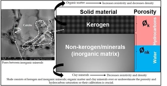
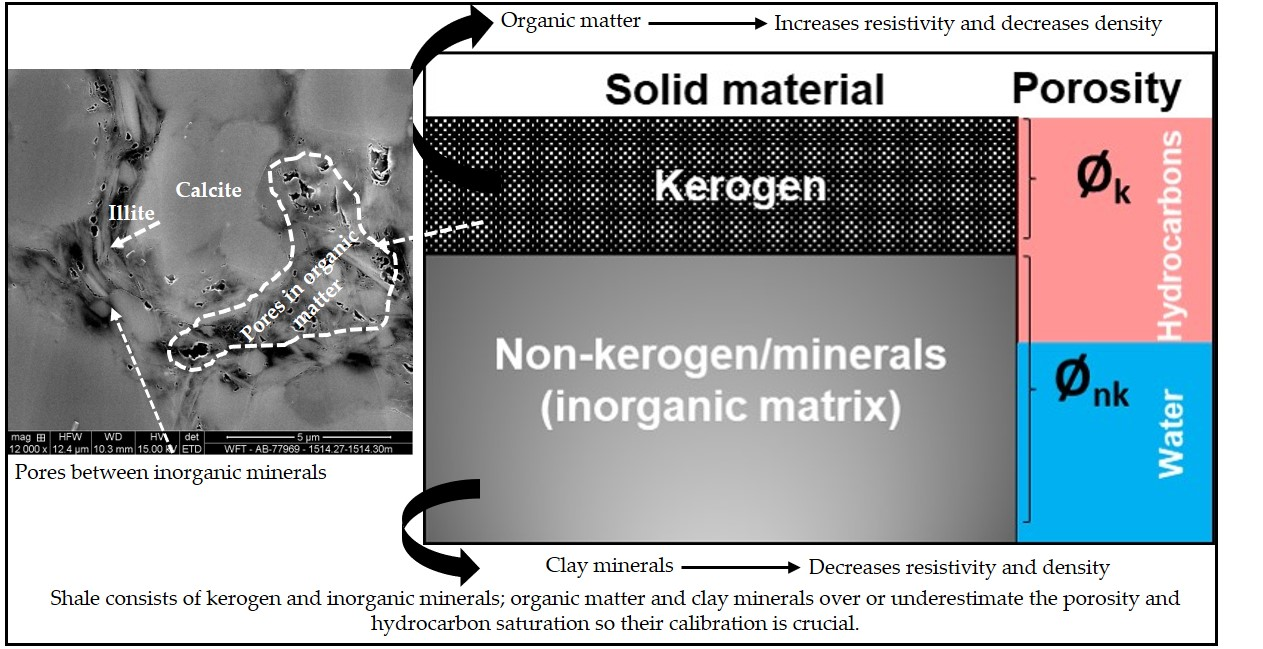
2.1. Porosity Estimation

The conventional density-based porosity equation is described in Equation (1):
Ø D =   ρ m a ρ b ρ m a ρ f
where Ø D   = density porosity (%), ρ m a = matrix density (g/cc), ρ b = bulk density (g/cc), ρ f = fluid density (g/cc). Unlike in conventional reservoirs (sandstone or limestone), the bulk density acquired through density log in organic-rich shale usually overestimates the porosity. Therefore, the kerogen correction is applied to avoid porosity overestimation. The kerogen volume is determined by using Equation (2) [25]:
V k =   γ × T O C × ρ b 100 × ρ k
where, V k is the kerogen volume (fractions); TOC is total organic carbon content (wt %); ρ b is the bulk density from the density log (g/cc); γ is the kerogen conversion factor; and ρ k is the kerogen density (g/cc). TOC is determined by the rock eval pyrolysis method on powdered shale samples, and the continuous TOC for the whole interval is estimated by Passey method [27]; γ is proposed by [25], and the selected values are shown in Table 1.
For this study, based on rock eval pyrolysis results, the kerogen types are 30% type-II and 70% type-III. Therefore, the kerogen conversion factor for the studied formation is calculated as 1.18; and ρ k is determined by the relationship of lab-based TOC and reciprocal of lab-based derived grain density on shale samples by the Equation (3). A good relationship between TOC and reciprocal of grain density ( ρ g read as RHOG) is observed in Figure 2. The Equation (3) is derived based on the relationship between TOC and reciprocal of grain density (Figure 2).
1 ρ g = A × T O C + B
ρ g is the matrix density if TOC is zero and ρ g k is kerogen density if TOC is 100%. A and B are based on the linear relationship seen in Figure 2. From the relation found in Figure 2, the matrix density for the samples of this study is 2.79 g/cc, and kerogen density is 1.24 g/cc. The well logs are calibrated by eliminating the kerogen effect, and the following equations Equations (4) and (5) are applied for matrix porosity estimation through density log:
ρ b k c =   ρ b ρ k × V k 1 V k
Ø k c =   ρ m a ρ b k ρ m a ρ f
where, ρ b k c   is kerogen corrected bulk density (g/cc); ρ k is kerogen density (g/cc); V k   is kerogen volume (fractions) and Ø k c is kerogen corrected density porosity (%). As the porosity in organic-rich shale is associated with organic matter and inorganic minerals, so it is crucial to estimate the porosity within organic matter (kerogen). An equation for kerogen porosity was proposed by [28] using mass-balance relation Equation (6).
Ø k = ( [ T O C o × C c ] × γ ) T R ρ b ρ k
where, Ø k = kerogen porosity (%), TOCo = original total organic carbon, Cc = convertible carbon fraction and TR = transformation ratio.
T O C o = T O C 1 T R × C c
T R = 1 H I p [ 1200 H I o ( 1 P I o ) ] H I o [ 1200 H I p ( 1 P I p ) ]
where: HIp = present hydrogen index (mg/g), HIo = original hydrogen index (mg/g), PIp = present production index and PIo = original production index. The following equations were used to estimate the original hydrogen index and present hydrogen index proposed by [28]:
H I o = T y p e I I 100 × 450 + T y p e I I I 100 × 125
For this study:
H I o = 225   mg / g
H I p = 170   mg / g
S1/S1 + S2 = P I p = 0.35
The convertible carbon fraction is determined by using the relationship proposed by [29], such as C c = 0.085 × H I o =18.91%.
Although, the transformation ratio (TR) can be determined by Claypool equation as explained in Equation (8) [28]. However, for this study, the TR value is taken as 88% that is adapted from [24,30] based on organic geochemistry and basin modelling of Goldwyer shale. So, the equation for kerogen porosity will be as Equation (10). By eliminating the kerogen effect and adding the kerogen porosity Equation (11), the final Equation (12) is applied to compute total density porosity for shale reservoirs.
Ø k = 0.2 × T O C × ρ b
Ø D T o t a l = [ ( ρ m a ρ b k c ρ m a ρ f ) + Ø k ]
Ø D T o t a l = [ ( ρ m a ( ρ b ρ k × V k 1 V k ) ρ m a ρ f ) + ( 0.2 × T O C × ρ b ) ]

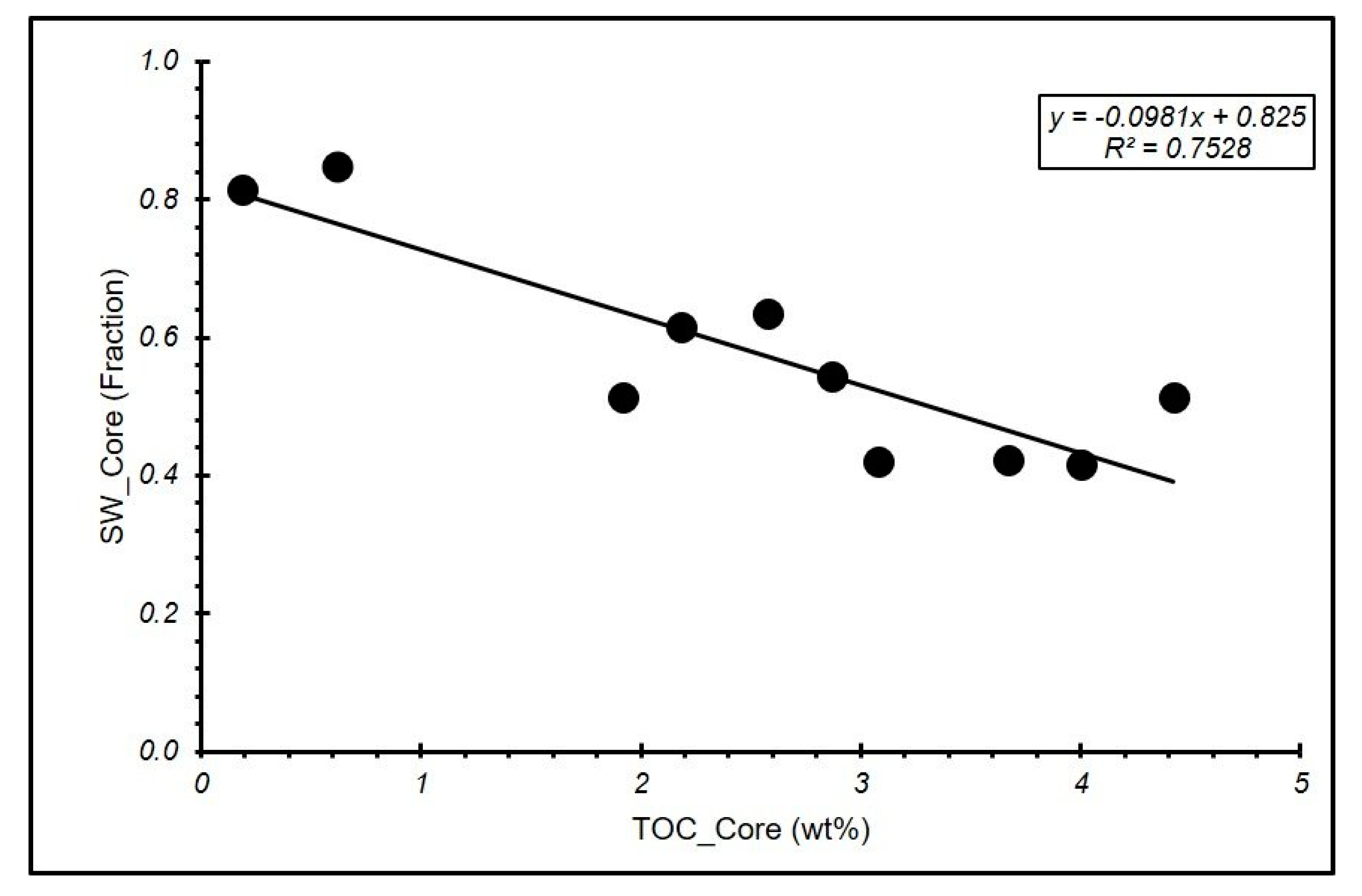
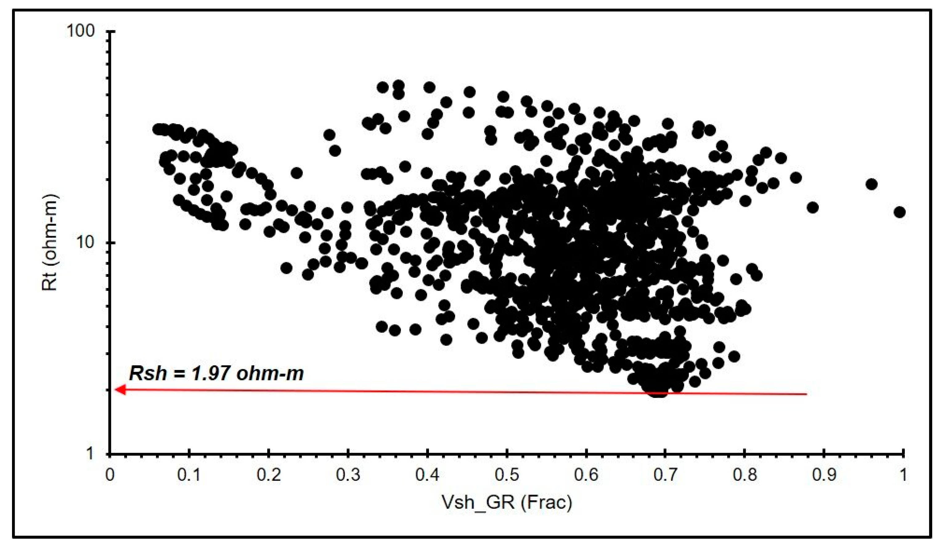
2.2. Calculation of Water Saturation

The water saturation estimation in shale is mainly dependent on its organic (kerogen) and inorganic components (minerals). Archie equation [17] is mainly popular for water saturation calculation in clean reservoirs. The equation was developed based on a function between formation conductivity and the conductivity of fluids in the pore spaces of a reservoir, such as:
C t = S w n × C w F
where C t = total conductivity (ohm−1 m−1), C w = formation water conductivity (ohm−1 m−1), n = saturation exponent usually equals to 2, S w = water saturation (%). The equation can be written in terms of resistivity as follows:
1 R t = Ø m × S w n a × R w
where R t = true resistivity measured by logging tool (ohm-m), Ø = porosity (%), m = cementation exponent, n = saturation exponent usually equals to 2, a = tortuosity factor usually considered as 1 and R w = formation water resistivity (ohm-m). The Equation (14) is known as the Archie equation for clean formations. Later, this equation did not provide acceptable and accurate results for the shaly formations. Therefore, other approaches such as Simandoux considered the shale effect on water saturation and developed an equation Equation (15) by considering the volume of shale in the equation that was further modified by Schlumberger, 1972 and the modified Simandoux equation is [18]:
1 R t = Ø m × S w n a . R w × ( 1 V s h ) + V s h × S w R s h
where R s h is the resistivity of shale (ohm-m) and V s h is the volume of shale (fraction). The conventional water saturation models, e.g., Simandoux equation, modified Simandoux, total shale, and modified total shale equations provided better results for shaly formations as these equations are derived based on the conductivities of clays and non-clay matrix. However, these models overestimate the water saturation for organic-rich shales. Therefore, a modified water saturation equation is applied in this study. An equation was proposed by [2,4] for water saturation calculation for shale reservoirs. The derivation details of the equation are explained by [17] simplified equation for water saturation:
S w = R o R t
where, R o is the rock resistivity in lean shale interval where water saturation is deemed 100% (ohm-m) and R t is the rock resistivity in the organic-rich shale reservoir with some degree of oil/gas saturation (ohm-m). Therefore, Ro and Rt are the key parameters for water saturation calculations.
As the organic-rich shale reservoirs have a higher content of total clay and organic matter it is necessary to conduct corrections (total organic carbon and total clay) for the true formation resistivity (Rt). The clay minerals decrease the formation resistivity and the kerogen increases the resistivity. So, the TOC and shale corrections are used for Rt. First, the correlation is developed between true resistivity log and TOC measurements (on powdered shale samples through rock eval pyrolysis) (Equation (17), Figure 3).
A negative correlation Equation (18) is found between laboratory-based water saturation measured on shale samples and rock eval pyrolysis-based TOC. This relationship shows that with the increase in TOC, the water saturation reduces that provides an indication of hydrocarbon saturation in the shale interval (Figure 4).
T O C = 0.1635 × R t
S w c o r e = 0.0981 × T O C c o r e + 0.825
The true resistivity is corrected in terms of subtracting a factor A Equation (19) due to TOC that can be evaluated by making arrangements, such as:
A = V k 2 × R k
If TOC is 100% then Rt will be considered as kerogen resistivity R k (based on Equation (17)) so for this study based on Figure 3 R k = 613 ohm-m and Figure 5 Rsh = 1.97 ohm-m are used.
Based on the correlation, the T O C m a x is found as 4.91 wt %. Another factor B Equation (20) because of clay minerals effect on resistivity is defined by many authors [18,31,32], such as:
B = V s h 2 × R o
The squared form of the shale volume will be more convincing in the calculation of reduced resistivity as a result of shale volume. It can be due to the nonlinear relationship between Ro and Rw in shales [18,31]. For this study, the Ro is taken as 1.97 ohm-m (Figure 5).
By compensating the shale and organic matter effects on the true resistivity, the modified equation is introduced as:
S w = R o R t ( V k r 2 × R k ) + ( V s h 2 × R s h )

3. Results and Discussion

In this section, the applications of proposed porosity and water saturation equations are implemented for the Ordovician Goldwyer shale formation drilled in Theia-1, Pictor East-1, and Canopus-1 wells in Canning Basin, Western Australia.
The kerogen corrected total porosity (matrix porosity plus kerogen porosity) was estimated by using Equation (12). The total porosity on crushed shale samples (core porosity) ranges from 2 to 13%, measured through the difference between the bulk volume of shale samples and the grain volume of the crushed, cleaned, and dried samples. The Goldwyer shale porosity shows the same range of porosity as most of the organic-rich shales [5,7,14,33,34,35,36]. The Goldwyer shale consists three types of pores such as organic pores, interparticle and intraparticle pores as shown in Figure 6. The results show that the conventional porosity estimation through density log overestimates the porosity that may affect the accurate reserve estimation in shale. Such as, the porosity based on Equation (1) provided the porosity range from 8 to 15% for Goldwyer shale (Figure 7). However, after applying the kerogen corrections, the corrected porosity ranging from 5 to 10% gives more accurate results that can be well-compared with core porosity (Table 2 and Figure 7). Moreover, the clay minerals also affect the pore structure of shale that directly affects the water saturation [37,38]. The Goldwyer shale also consists interparticle pores influenced by illite that may change the water saturation (Figure 6). The core derived TOC varies from 0.35 to 4.5 wt % in this study. The log derived TOC matches well with core-based TOC and the equivalent kerogen volume also validates the results (Figure 7). It can also be observed in Table 2 and Figure 7 that the clusters (e.g., siliceous and argillaceous shales) with higher TOC value have higher porosity (about 8–10%) due to the addition of organic pores (kerogen porosity) in the matrix porosity.
The water saturation was estimated by Equation (21) by considering the kerogen and shale effects on the resistivity. The required kerogen volume and kerogen resistivity were computed by using the data set (well logs) and core information from three wells (Theia-1, Pictor East-1 and Canopus-1) drilled in Canning Basin. The results for Theia-1 well are illustrated in Figure 7. Similarly, the shale resistivity was taken based on the data set for these three wells. It can be observed in Figure 7 that with the increase in shale volume (e.g., at depth 1546.5 m), the deep resistivity is decreased that enhances the water saturation. In conventional reservoirs, shale resistivity is usually determined from the averaged deep resistivity log reading against shale interval having higher gamma-ray log reading. However, in shale reservoirs, the shale resistivity is obtained from the average reading of the deep resistivity log against an organic lean interval. In this study, the shale resistivity in the organic lean interval is determined as 1.97 ohm-m based on the relationship between shale volume and true resistivity developed by this study (Figure 5). It is impractical to determine the fluid-water contact in heterogeneous shale reservoirs; therefore, an organic lean shale is treated to be fully brine saturated rock, Sw = 1 [4].
In the same way, the zones with higher TOC value and kerogen volume (such as organic-rich siliceous shale–cluster 3 (siliceous shale) at depth 1550 m) have the lowest water saturation. The inverse relationship between core-based TOC and Sw is also confirmed in this study (Figure 4). So, the kerogen resistivity ( R k r = 613 ohm-m) is determined by Equation (17) by putting TOC value as 100%. Therefore, the modified Archie equation applied in this study provides much better results (well correlated with core derived Sw) than the Simandoux equation (Table 2 and Figure 7). It can be observed that the Simandoux method overestimated water saturation as it is impossible to have more than 100% Sw. Another key factor of this overestimation is inaccurate determination of water resistivity and cementation exponent (m) values. Therefore, the modified Archie equation applied in this study is simple and accurate subject to the resistivity corrections for shale and kerogen.

4. Conclusions

In this research, effective equations for two critical petrophysical parameters of shale reservoirs (total porosity and water saturation) have been introduced. These equations are compensated based on kerogen effects for density logs to estimate more accurate total porosity. Similarly, the resistivity log was corrected based on kerogen and shale effects to compute the accurate water saturation for shale reservoirs. This study shows that the density log overestimates the total porosity (8–15%). Whereas the total porosity based on kerogen corrected density log and kerogen porosity matches perfectly with the core-based porosity having porosity ranged from 5 to 10%. In the same way, the Simandoux equation overestimated the water saturation with more than 100% Sw in most of the intervals. However, the proposed water saturation equation (modified Archie’s equation) provided better results and correlation with core-based water saturation ranged from 35 to 80%. Moreover, the introduced modified Archie equation is independent of water resistivity and Archie parameters as these inputs are very difficult to obtain for shale reservoirs. It is also revealed that the porosity and water saturation in shale reservoirs are mainly dependent on the specific rock type. Such as the cluster-2 (mixed shale lithofacies with mixed lithologies and moderate TOC value) and cluster-3 (siliceous shale lithofacies with higher silica, less clay content and moderate to high TOC) have more shale gas potential in Goldwyer shale due to higher porosity and water saturation. This study has proposed a step to step workflow for accurate estimation of porosity and water saturation based on well logs for organic-rich shale. This workflow will be helpful for accurate reserve estimations in the shale reservoirs.

Author Contributions

Conceptualisation, M.A.I.; methodology, M.A.I, and R.R.; software, M.A.I.; data curation, M.A.I.; validation, M.A.I. and R.R.; writing—original draft, M.A.I.; writing—review and editing, R.R.; supervision, R.R. All authors have read and agreed to the published version of the manuscript.

Funding

This research received no external funding.

Acknowledgments

The authors would like to acknowledge the contributions of Chief Minister Merit Scholarship (CMMS), Pakistan and the Unconventional Gas Research group at the department of Petroleum Engineering, Western Australia School of Mines: Minerals, Energy and Chemical Engineering, Curtin University and Senergy Interactive Petrophysics v4.5 software for supporting this research. Special thanks to Department of Mines Industry Regulation and Safety (DMIRS) Western Australia and Finder Exploration Pty Ltd. (Perth, Western Australia). for providing data and reports about core-based measurements for water saturation.

Conflicts of Interest

The authors declare no conflict of interest.

Nomenclature

Ø D density porosity
ρ ma matrix density
ρ b bulk density
ρ f fluid density
ρ b bulk density (g/cc)
γ kerogen conversion factor
ρ k kerogen density (g/cc).
ρ g grain density
ρ b k kerogen corrected bulk density
Ø porosity
Ø k kerogen porosity
Ø D Total total density porosity
a tortuosity factor
Ccconvertible carbon fraction
C t total conductivity
C w formation water conductivity
HIppresent hydrogen index
HIooriginal hydrogen index
mcementation exponent
nsaturation exponent
PIppresent production index
PIooriginal production index
R w formation water resistivity
R s h resistivity of shale
R t true resistivity in ohm-m
R o the rock resistivity in lean shale interval where water saturation is deemed 100%
RkKerogen resistivity
S w water saturation
TOCtotal organic carbon content
TOCooriginal total organic carbon
TRtransformation ratio
V k kerogen volume in fractions
V sh volume of shale

References

  1. Jenner, S.; Lamadrid, A.J. Shale gas vs. coal: Policy implications from environmental impact comparisons of shale gas, conventional gas, and coal on air, water, and land in the United States. Energy Policy 2013, 53, 442–453. [Google Scholar] [CrossRef] [Green Version]
  2. Rezaee, R. Fundamentals of Gas Shale Reservoirs; John Wiley & Sons: Hoboken, NJ, USA, 2015. [Google Scholar]
  3. Ross, D.J.K.; Bustin, R.M. The importance of shale composition and pore structure upon gas storage potential of shale gas reservoirs. Mar. Pet. Geol. 2009, 26, 916–927. [Google Scholar] [CrossRef]
  4. Kadkhodaie, A.; Rezaee, R. A new correlation for water saturation calculation in gas shale reservoirs based on compensation of kerogen-clay conductivity. J. Pet. Sci. Eng. 2016, 146, 932–939. [Google Scholar] [CrossRef] [Green Version]
  5. Yu, H.; Wang, Z.; Rezaee, R.; Zhang, Y.; Han, T.; Arif, M.; Johnson, L. Porosity estimation in kerogen-bearing shale gas reservoirs. J. Nat. Gas Sci. Eng. 2018, 52, 575–581. [Google Scholar] [CrossRef]
  6. Walls, J.D.; Sinclair, S.W. Eagle Ford shale reservoir properties from digital rock physics. First Break 2011, 29. [Google Scholar] [CrossRef]
  7. Sondergeld, C.H.; Newsham, K.E.; Comisky, J.T.; Rice, M.C.; Rai, C.S. Petrophysical Considerations in Evaluating and Producing Shale Gas Resources. In Proceedings of the SPE Unconventional Gas Conference, Society of Petroleum Engineers, Pittsburgh, PA, USA, 23–25 February 2010; p. 34. [Google Scholar]
  8. Kale, S.; Rai, C.; Sondergeld, C. Rock Typing in Gas Shales. In Proceedings of the SPE Annual Technical Conference and Exhibition, Society of Petroleum Engineers, Florence, Italy, 19–22 September 2010; p. 20. [Google Scholar]
  9. Ambrose, R.J.; Hartman, R.C.; Diaz-Campos, M.; Akkutlu, I.Y.; Sondergeld, C.H. Shale gas-in-place calculations part I: New pore-scale considerations. Spe J. 2012, 17, 219–229. [Google Scholar] [CrossRef]
  10. Yu, H.; Rezaee, R.; Wang, Z.; Han, T.; Zhang, Y.; Arif, M.; Johnson, L. A new method for TOC estimation in tight shale gas reservoirs. Int. J. Coal Geol. 2017, 179, 269–277. [Google Scholar] [CrossRef] [Green Version]
  11. Jacobi, D.J.; Breig, J.J.; LeCompte, B.; Kopal, M.; Hursan, G.; Mendez, F.E.; Bliven, S.; Longo, J. Effective geochemical and geomechanical characterization of shale gas reservoirs from the wellbore environment: Caney and the Woodford shale. In Proceedings of the SPE Annual Technical Conference and Exhibition, Society of Petroleum Engineers, New Orleans, LA, USA, 4–7 October 2009. [Google Scholar]
  12. Fu, Q.; Horvath, S.C.; Potter, E.C.; Roberts, F.; Tinker, S.W.; Ikonnikova, S.; Fisher, W.L.; Yan, J. Log-derived thickness and porosity of the Barnett Shale, Fort Worth basin, Texas: Implications for assessment of gas shale resources. Aapg Bull. 2015, 99, 119–141. [Google Scholar] [CrossRef]
  13. Arredondo-Ramírez, K.; Ponce-Ortega, J.M.; El-Halwagi, M.M. Optimal planning and infrastructure development for shale gas production. Energy Convers. Manag. 2016, 119, 91–100. [Google Scholar] [CrossRef]
  14. Yuan, Y.; Rezaee, R.; Al-Khdheeawi, E.A.; Hu, S.-Y.; Verrall, M.; Zou, J.; Liu, K. Impact of Composition on Pore Structure Properties in Shale: Implications for Micro-/Mesopore Volume and Surface Area Prediction. Energy Fuels 2019, 33, 9619–9628. [Google Scholar] [CrossRef]
  15. Yuan, Y.; Rezaee, R.; Verrall, M.; Hu, S.-Y.; Zou, J.; Testmanti, N. Pore characterization and clay bound water assessment in shale with a combination of NMR and low-pressure nitrogen gas adsorption. Int. J. Coal Geol. 2018, 194, 11–21. [Google Scholar] [CrossRef]
  16. Labani, M.M.; Rezaee, R.; Saeedi, A.; Al Hinai, A. Evaluation of pore size spectrum of gas shale reservoirs using low pressure nitrogen adsorption, gas expansion and mercury porosimetry: A case study from the Perth and Canning Basins, Western Australia. J. Pet. Sci. Eng. 2013, 112, 7–16. [Google Scholar] [CrossRef]
  17. Archie, G.E. The electrical resistivity log as an aid in determining some reservoir characteristics. Trans. AIME 1942, 146, 54–62. [Google Scholar] [CrossRef]
  18. Simandoux, P. Dielectric measurements in porous media and application to shaly formation: Revue del’Institut Francais du Petrole. Suppl. Issue 1963, 18, 193–215. [Google Scholar]
  19. Wang, F.P.; Gale, J.F. Screening Criteria for Shale-Gas Systems. Gulf Coast Association of Geological Societies Transactions: Tulsa, OK, USA, 2009; Volume 59, pp. 779–793. [Google Scholar]
  20. Bust, V.K.; Majid, A.A.; Oletu, J.U.; Worthington, P.F. The petrophysics of shale gas reservoirs: Technical challenges and pragmatic solutions. Pet. Geosci. 2013, 19, 91–103. [Google Scholar] [CrossRef]
  21. Akbar, M.N.A.; Musu, J.T.; Milad, B. Water Saturation Interpretation Model for Organic-Rich Shale Reservoir: A Case Study of North Sumatra Basin. In Proceedings of the Unconventional Resources Technology Conference (URTEC), Houston, TX, USA, 23–25 July 2018. [Google Scholar]
  22. Haines, P. Depositional Facies and Regional Correlations of the Ordovician Goldwyer and Nita Formations, Canning Basin, Western Australia, with Implications for Petroleum Exploration; Geological Survey of Western Australia, Record: East Perth, WA, Australia, 2004; p. 7. [Google Scholar]
  23. Johnson, L.M.; Rezaee, R.; Kadkhodaie, A.; Smith, G.; Yu, H. Geochemical property modelling of a potential shale reservoir in the Canning Basin (Western Australia), using Artificial Neural Networks and geostatistical tools. Comput. Geosci. 2018, 120, 73–81. [Google Scholar] [CrossRef]
  24. Johnson, L.M. Integrated Reservoir Characterization of the Goldwyer Formation, Canning Basin; Curtin University, Perth, Western Australia, 2019.
  25. Tissot, B.P.; Welte, D.H. Diagenesis, Catagenesis and Metagenesis of Organic Matter, in Petroleum Formation and Occurrence; Springer: Berlin/Heidelberg, Germany, 1984; pp. 69–73. [Google Scholar]
  26. Espitalie, J.; Madec, M.; Tissot, B.; Mennig, J.; Leplat, P. Source rock characterization method for petroleum exploration. In Proceedings of the Offshore Technology Conference, Houston, TX, USA, 2–5 May 1977. [Google Scholar]
  27. Passey, Q.; Creaney, S.; Kulla, J.; Moretti, F.; Stroud, J. A practical model for organic richness from porosity and resistivity logs. Aapg Bull. 1990, 74, 1777–1794. [Google Scholar]
  28. Peters, K.E.; Walters, C.; Moldowan, J.M. Biomarkers and Isotopes in the Environment and Human History; Cambridge University Press: Cambridge, UK, 2005. [Google Scholar]
  29. Kilgore, E.; Land, A.; Schmidt, A.; Yunker, J. Applications of the Coriband Technique to Complex Lithologies. Log Anal. 1972, 13, 24. [Google Scholar]
  30. Johnson, L.M.; Rezaee, R.; Smith, G.C.; Mahlstedt, N.; Edwards, D.S.; Kadkhodaie, A.; Yu, H. Kinetics of hydrocarbon generation from the marine Ordovician Goldwyer Formation, Canning Basin, Western Australia. Int. J. Coal Geol. 2020, 232, 103623. [Google Scholar] [CrossRef]
  31. Leveaux, J.; Poupon, A. Evaluation of water saturation in shaly formations. Log Anal. 1971, 12, 6. [Google Scholar]
  32. Clavier, C.; Coates, G.; Dumanoir, J. Theoretical and Experimental Bases forthe Dual-Water Model for the Interpretation of Shaly Sands. Soc. Pet. Eng. J. 1984, 24, 153–167. [Google Scholar] [CrossRef]
  33. Chalmers, G.R.; Bustin, R.M.; Power, I.M. Characterization of gas shale pore systems by porosimetry, pycnometry, surface area, and field emission scanning electron microscopy/transmission electron microscopy image analyses: Examples from the Barnett, Woodford, Haynesville, Marcellus, and Doig units. Aapg Bull. 2012, 96, 1099–1119. [Google Scholar]
  34. Wu, T.; Li, X.; Zhao, J.; Zhang, D. Multiscale pore structure and its effect on gas transport in organic-rich shale. Water Resour. Res. 2017, 53, 5438–5450. [Google Scholar] [CrossRef]
  35. Wei, W.; Zhu, X.; Meng, Y.; Xiao, L.; Xue, M.; Wang, J. Porosity model and its application in tight gas sandstone reservoir in the southern part of West Depression, Liaohe Basin, China. J. Pet. Sci. Eng. 2016, 141, 24–37. [Google Scholar] [CrossRef]
  36. Mastalerz, M.; Schimmelmann, A.; Drobniak, A.; Chen, Y. Porosity of Devonian and Mississippian New Albany Shale across a maturation gradient: Insights from organic petrology, gas adsorption, and mercury intrusion. Aapg Bull. 2013, 97, 1621–1643. [Google Scholar] [CrossRef]
  37. Tian, H.; Wang, M.; Liu, S.; Zhang, S.; Zou, C. Influence of Pore Water on the Gas Storage of Organic-Rich Shale. Energy Fuels 2020, 34, 5293–5306. [Google Scholar] [CrossRef]
  38. Cao, T.; Xu, H.; Liu, G.; Deng, M.; Cao, Q.; Yu, Y. Factors influencing microstructure and porosity in shales of the Wufeng-Longmaxi formations in northwestern Guizhou, China. J. Pet. Sci. Eng. 2020, 191, 107181. [Google Scholar] [CrossRef]
Figure 1. A typical conceptual petrophysical model for shale reservoirs showing kerogen porosity Øk and non-kerogen Ønk (inorganic matrix) porosity, modified from Yu et al. [5].
Energies 13 06294 g001
Figure 2. The direct relationship between core-based derived total organic carbon and reciprocal of grain density providing helpful information for estimation of kerogen and matrix densities.
Energies 13 06294 g002
Figure 3. Direct relationship between true resistivity and measured total organic carbon showing influence of organic matter on resistivity tool.
Energies 13 06294 g003
Figure 4. An inverse relationship between core-based total organic carbon and water saturation showing the fact that the organic matter increases gas saturation.
Energies 13 06294 g004
Figure 5. The shale resistivity estimation based on shale volume and true resistivity relationship.
Energies 13 06294 g005
Figure 6. Different pore types observed in Goldwyer shale based on scanning electron microscope images, such as (a) interparticle pores indicated by white arrows and intraparticle pores indicated by red arrows; (b) organic matter pores (OM), mineral components include calcite (cal), quartz (qtz) and illite.
Energies 13 06294 g006
Figure 7. Petrophysical evaluation of Goldwyer shale providing accurate estimation of porosity and water saturation through proposed equations as validated by core-based measurements. Track-1: Depth in meters; Track-2: Cluster analysis to identify cluster based facies; Track-3: Gamma ray log; Track-4: Deep resistivity log; Track-5: Density log; Track-4: Sonic (DT) log; Track-4: Kerogen volume; Track-4: Shale volume based on Gamma ray log; Track-4: TOC based on Passey’s method and core measurements; Track-4: Kerogen corrected total density porosity (PHIDKc) based on proposed equation in this study, density based porosity (PHID) & Total porosity based on core samples; Track-4: Water saturation (Sw) based on Simandoux equation (overestimated) and modified Archie’s equation (by this study) and core derived Sw.
Energies 13 06294 g007
Table 1. Conversion factors for total organic carbon (TOC) to kerogen, adapted from Tissot and Welte [25].
StageType of Kerogen
IIIIII
Diagenesis1.251.341.48
End of Catagenesis1.201.191.18
Table 2. Comparison of averaged total porosity and water saturation determined by conventional equations (PHID and Sw_Simandoux) and introduced by this study (PHIDKc and Sw_modified Archie). The conventional equations overestimated the porosity and water saturation in shale.
ClusterLithofaciesTOCPHIDKcSw_Modified ArchiePHIDSw_Simandoux
(wt. %)%%%%
Cluster-1
(Blue)
Calcareous shale0.7555690
Cluster-2
(Olive)
Mixed shale1.48.5451080
Cluster-3
(Yellow)
Siliceous shale2.58351245
Cluster-4
(Grey)
Argillaceous shale3.598013>100
Publisher’s Note: MDPI stays neutral with regard to jurisdictional claims in published maps and institutional affiliations.

