1. Introduction
One of the main aims when erecting buildings is to assure safety and comfort for their users. In the context of climate change and the depletion of non-renewable energy resources (e.g., gas, coal, oil etc.), contemporary construction faces an additional challenge: buildings must be energy-efficient and renewable energy sources should be used for supplying them. In cold and moderate climates, the energy demand for heating exceeds the energy demand for cooling purposes. The forecast of cooling needs increase, described in Ref. [
1] (by 7.5 times for residential buildings) may bring some change on this field in the nearest future. For that reason, there is a growing interest in the various methods of natural shading and limiting the influence of solar radiation on thermal comfort in the buildings, which was described in Ref. [
2]. Nevertheless, in cold and moderate climates, buildings have to be heated. In order to save primary energy, legal requirements, e.g., in the European Union, have specified that modern buildings need to be well-insulated. Achieving reduced energy consumption for heating is also favored by the air-tightness of the building envelope and ventilation systems with heat recovery, which was described in Ref. [
3]. The energy consumption for heating the ventilation air in winter and cooling it in summer can be reduced even further by using earth-to-air heat exchangers to preheat or precool external air [
4,
5]. Another way to reduce the energy consumption of heating systems is their hydraulic balancing—currently, more attention is paid to this issue. Ref. [
6] has described the importance of proper regulation and zoning of heating installations for energy savings, which resulted in energy savings from 14.6% to 23.8%, and Ref. [
7] revealed that the use of thermostatic valves for radiators can result in energy savings from 7.1% to 23.3%. The importance of appropriate zoning of the heating system based on radiant ceiling panels was also emphasized in Ref. [
8], in addition to the necessity to use appropriate algorithms for controlling their operation in order to obtain thermal comfort of users. On the other hand, thermo-modernization seems to be energetically and economically justified. In Ref. [
9], it was shown that retrofitting of a building can result in energy savings of 30%. In a holistic approach, however, it seems to be more justified to use multi-criteria assessment methods, such as, for example, the global cost method, which was presented, for example, in Refs. [
10,
11] for the purpose of assessing thermo-modernization projects.
Thanks to, among others, the trends, treatments and systems described in the first paragraph of the introduction, the heat demand of contemporary and retrofitted buildings expressed in W/m
2 is small enough to use low-temperature heating systems, especially surface heating (floor, ceiling, wall). The use of solar, wind and ground energy is effective mainly in cooperation with the systems mentioned above. From the Ref. [
12], it appears that surface heating is conducive to the feeling of good thermal comfort, especially if it cooperates, in an appropriate way, with the ventilation system. Better thermal comfort of wall heating systems may result from several reasons, but the most important seem to be: (i) preferred way of heat transfer—mainly by radiation, (ii) less asymmetry of thermal radiation between warm internal partitions and cold external partitions of the building, (iii) even distribution of temperature in the room along its entire height. Better thermal comfort of radiant heating systems was raised in Ref. [
13], where the authors performed an overview of the usage of such systems in large halls consuming huge amount of energy, or in Ref. [
14], where the combined convection-radiant system was tested. Lowering the temperature of the medium supplying the heating system reduces heat losses during its distribution and contributes to obtaining a higher efficiency of popular heat sources: condensing gas boilers (longer period when the condensation occurs) or heat pumps (higher
COP = Coefficient of Performance). The issues of modeling and simulation of various types of surface heating systems based on water loops are commonly tested. Each manufacturer of pipes, mats or wall, floor or ceiling panels has appropriate selection cards based on the calculations of the thermal performance. These data are based on the results of studies such as Refs. [
15,
16], which focused on the experimental determination of heat transfer coefficients between surface and room. In these systems, water flows through the water loop and further in the building partition under the plaster layer, causing its surface to heat up/cool down. The thermal effect is fairly easy to predict in these systems, if the following data are known: heat conduction resistance of each of the layers of the building partition, heat transfer coefficient from the partition surface and emissivity of the surface (heat exchange by radiation). Ref. [
17] proposed a modification of the method for determining the efficiency of underfloor heating recommended by the current standards, achieving an even better convergence between the results of the calculations and experimental tests. More complex systems use a phase change material to accumulate energy and increase the efficiency, as has been described, inter alia, in Refs. [
18,
19]. The review of research on surface heating systems presented above confirmed the existing knowledge of the thermal issues of these types of systems.
Among the innovative radiant heating systems, underfloor heating systems are the most frequently tested, but not only. In Ref. [
20], the corrugation of the heating surface aluminum panel was investigated, causing an increase in thermal performance not only due to the larger heat exchange surface, but also as a result of the intensification of heat transfer by natural convection. Experimental investigations of heating panel system presented in Ref. [
20] were similar to the present work from the methodological point of view, but they were taken into account a water loop system based on water flowing through the interior of the ceiling panel. In this paper a completely different system is investigated based on the refrigerant closed in heat pipes in wall-type system. In Ref. [
21], the authors analyzed the energy and economic performance of the prefabricated electric radiant floor system; the main difference between actual investigations is that it is focused on the floor heating and with the usage of the electricity without water and/or refrigerant gas. Infrared (IR) photos presented in Ref. [
22] show that the temperature distribution in the electric floor heating system is more uniform than in a water loop system. In Ref. [
23], the thermoelectric radiant ceiling panel was tested differing from panels investigated in this paper with the construction: the aluminum ceiling plate was connected with a thermoelectric module that heats it up using electricity. In the devices used in the present investigations, heat is provided to the wall by means of heat pipes heated up by the hot water from the bottom collector. In Refs. [
24,
25,
26], the capillary tube floor mats were tested, showing the significant annual energy reduction for heating thanks to their thermal characteristics. The heating surface is heated in such devices by micro tubes (capillary) filled with hot water. Capillary tubes were also tested as a device for heating in a ceiling mode, which was presented in Ref. [
27]. A novel radiant-convective heating system was tested in Refs. [
28,
29] as having advantages from both radiant and convective systems. In both systems, heating panels with pipes similar to those investigated in the present paper were not used.
The systems discussed above are based on water loops or electricity, and their operation and the ability to control their efficiency have been thoroughly explored. A different type of surface heating system consists of wall heating panels with heat pipes, investigated in this paper. This system is not very popular and is only just entering the heating equipment market, although heat pipes are widely used in applied heat engineering. One of their main advantages is an ability to work in an aggressive environment and the separation of the clean side of a given process of heat exchange from its dirty side. Usually, this effect cannot be achieved using exchangers sensitive for dirt and aggressive environment such as plate-type, tube-in-tube or shell-tube exchangers. For these reasons, heat pipes have been used, among others, in so-called waste heat recovery systems. In Refs. [
30,
31], the heat pipe device was presented as an efficient tool for heat recovery during the cooling process of production of steel. In Refs. [
32,
33], the heat pipe heat exchanger was tested for heat recovery from the laboratory scale ceramic kiln (from exhausted gases to water). The results of the investigations presented in Ref. [
34] show that heat pipes can also be used to improve the efficiency of the cooling system in air handling units working in hot and humid climates. Heat pipe heat exchangers were also tested for dehumidifying air in heating, ventilation and air conditioning (HVAC) systems for tropical climates [
35,
36]. Heat pipe systems in air handling units can also be used to utilize the waste energy to preheat or precool fresh air and as a result diminish the energy consumption for heating and ventilating the building, which was presented, among others, in Ref. [
37]. Heat pipe systems are commonly used for harvesting the solar energy as evidenced by numerous research studies on the efficiency, efficiency improvement and the possibility of using them for the purpose of preparing domestic hot water for washing, for example, in Refs. [
38,
39,
40,
41,
42], to mention only a few. A very interesting application of heat pipes is their usage for heating the pavement in winter using solar energy harvested with the evacuated tube collectors, which was described in Ref. [
43]. In Ref. [
44], the multi-channel heat pipe system was investigated experimentally and numerically. The main difference between this type of system and the system investigated in this paper is the presence of a common lower and upper collector in the application presented in Ref. [
44] and a flat aluminum plate as a heat transfer surface. This kind of heat exchanger is dedicated for some kinds of industrial purposes and the device presented in this study is strictly dedicated for purposes of heating the buildings.
The systems described in the preceding paragraphs present a different use of heat pipes than the system tested in this paper. To the best of the authors’ knowledge, no examples of the use of wall panels with heat pipes for building heating purposes have been presented in the literature. This type of surface heating system can, therefore, be considered a niche and innovative. In this paper, a novel wall-type heating panel is investigated experimentally. The lack of results of research on the thermal performance of such systems and the lack of research showing the possibility of controlling their thermal power in order to adjust it to the actual heating demand were indicated in this article as a knowledge gap. This was the reason for undertaking this research, which is aimed at determining the experimental thermal characteristics of an exemplary construction of wall heating panels with heat pipes and determining the possibility of controlling their thermal performance by changing the mass flowrate of heating water and/or its temperature.
2. Materials and Methods
2.1. Description of the Investigated Heating Panels
The structure and principle of the operation of investigated heating panels differ significantly from the systems discussed in the introduction.
Figure 1 shows schematically the construction of an exemplary device. In the system of wall panels with heat pipes, heating water from the heat source flows through pipes located at the floor of the heated room. The water supplies a group of panels, divided into loops, similar to a typical floor or wall heating loops. The main difference is that the heating water does not flow through the wall panel and does not come into contact with the partition surface either directly or through the pipes. In the investigated devices there are heat pipes (4,
Figure 1) located under the layer of plaster or drywall on the wall. In this particular model, the panel consists of three heat pipes with an internal diameter of 8 mm filled with refrigerant, connected by a common manifold (2,
Figure 1) immersed in the pipe with heating water flowing from the heat source. The working fluid (3,
Figure 1) closed in the heat pipes evaporates intensively as a result of heating by the heating water. Its vapors (5,
Figure 1) rise spontaneously (by gravity) and are cooled down in the upper part of the panel. Thus, they heat the surface of the partition in which they are installed. Cooling down the refrigerant vapor causes its condensation and the gravitational drainage of the condensate down to the manifold (2,
Figure 1). Then, the cycle repeats itself. Heat pipes are responsible for the heat transfer from the heating water to the wall surface and, consequently, to the heated room.
In this study, wall heating panels with heat pipes built under a layer of plasterboard were analyzed.
Figure 2 shows a photo of the three panels that were tested. Each panel has three heat pipes, filled with refrigerant, connected at the bottom by a common manifold. This collector is mounted on the axis of a circular pipe, through which the heating water flows from the heat source. The heat supplied to the collector washed with heating water causes intensive evaporation of the working fluid. Working fluid vapor rises up along the height of the heat pipes installed in the panel (by gravity) and is cooled down as a result of heat exchange between the heat pipes and the air in the room. In order to distribute heat better over the entire surface of the panel, heat pipes were attached to aluminum mesh. As a result of the cooling of the working fluid vapors, it becomes a liquid and flows down to the collector by gravity, where it heats up, and the cycle repeats itself. During the process of condensation, the temperature of the working fluid is constant.
The movement of the working fluid in the heat pipe is triggered spontaneously (by gravity), so no pumps or other devices powered by electricity or heat are needed for this purpose. As a result, the panels can be perceived as energy-saving, because for their operation, it is only necessary to overcome a slight resistance to water flow through a pipe with a collector immersed in it. The flow coefficient for three investigated panels connected in a row is kv = 1.43 m3/h, which results in a pressure drop of 0.06 kPa to 1.43 kPa, assuming the water mass flowrate correspondingly m = 10 g/s to 47.5 g/s (range of mass flows tested in this work). Typical pressure drops designed in case of the floor heating systems are about 10–15 (20) kPa. It has to be mentioned that heating panels have to be connected with pipes supplying hot water. For this reason, the total pressure losses would be higher. Assuming the length of the supplying and returning installation in the room L = 15 m and internal diameter of pipes d = 0.01 m, the total pressure losses of panels + installations would be 0.8 kPa to 14.93 kPa for m = 10 g/s to 47.5 g/s, correspondingly. It means that for low mass flowrates, heating panels with heat pipes can generate pressure losses much lower than the circuit of the floor heating system, but for higher mass flowrates, total pressure losses can be similar. In the present study, the influence of mass flowrate on the specific thermal power of the panel is tested to judge if it is worth to obtain higher thermal power by using high mass flowrates of the heating water.
2.2. Experimental Set-Up
Heating panels obtained for the tests have built-in heat pipes filled with the R134a refrigerant (boiling temperature −26 °C). The manufacturer does not provide information on the amount of refrigerant used or the filling pressure, leaving this information as know-how. From a technological point of view, the repeatability of the degree of filling the pipes with refrigerant may not be ideal; hence, the decision was made to test a set of three panels at a time and take the averaged values of their thermal power. The second reason for making this decision is an attempt to reflect their typical working conditions in a group within one water circuit. The third reason and justification for undertaking the tests of a set of three panels is the low temperature drop on a single panel recorded during the initial tests. The measurement of a small temperature difference is burdened with a large relative error. Connecting panels in a row results in (i) more reliable measurement of temperature drop (higher value) and (ii) averaged thermal power for three panels working as a single module in one water loop regardless of the degree of repeatability of production. This simplification is justified due to the small temperature drops on a single panel, which makes the operating parameters of the first and the last panel very similar to each other. It has to be noticed that due to this simplification, the presented averaged results cannot be used to validate the detailed numerical models of the heat exchange taking place in these panels. The purpose of this research is to analyze the sensitivity of the average thermal power of panels to the change of parameters: mass flowrate and temperature of supply water. This simplification was regarded as suitable for achieving this aim.
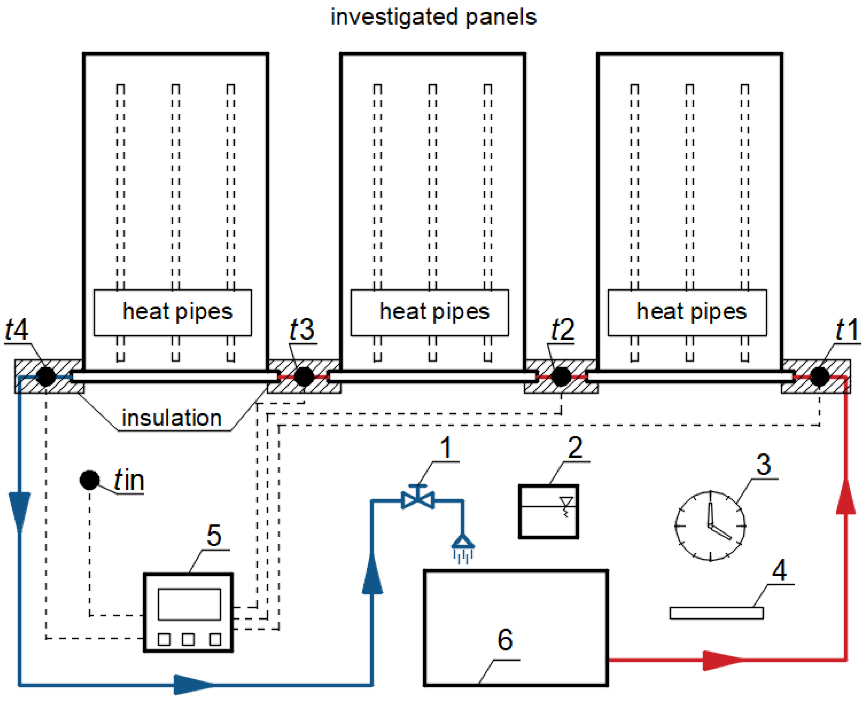
In order to determine the thermal characteristics of three wall heating panels with heat pipes, experimental studies were carried out. The view of the panels is presented in
Figure 2 and the scheme of the experimental set-up is shown in
Figure 3. The measuring devices and their accuracy are listed in
Table 1. Thermal performance tests consisted of measuring the following quantities:
m1—heating water mass flowing through the panels during the measurement,
τ—time of gathering the heating water into a measuring vessel,
t1, t2, t3—temperature of the water supplying: first, second and third panel, respectively,
t4—temperature of the water flowing from the third panel,
tin—air temperature in the test chamber.
The length of the pipes connecting the panels (between them) was equal to 0.5 m (50d, d = 0.01 m). Pipes were insulated with typical polyethylene foam of a diameter of 0.022 m (thickness of the insulation layer was 0.009 m, λ = 0.040 W/m/K). Due to the short length of the connecting sections and their thermal insulation, it was assumed that the heat losses in these sections are negligible for the purpose of determining the intensity of the influence of the supply water mass flowrate and temperature on the thermal efficiency of the panels. The bottom side of the panel (manifold) was insulated with PE foam of a thickness 0.009 m. Heat losses from the manifold to the room were not calculated/estimated in the research, because they were considered negligible (thanks to the insulation) and treated as a part of the heating power of the panel affecting the heating of air in the room as rest of the area of the panel.
The side surfaces and the rear surface of the panel were insulated with 15 cm thick polystyrene (λ = 0.040 W/m/K, thermal resistance R = 3.75 m2K/W). For this reason, the heat losses from the rear wall of the panels were considered negligible.
The mass flowrate (m) of water flowing through the panels was determined with the weight method:
where
m1 is the mass of water gathered to a measuring vessel and
τ is a time of gathering the water.
The specific power of each panel (
qi, where
i = 1, 2 or 3) was determined with the knowledge of the specific heat of water, which was assumed as
cw = 4190 J/kg/K:
where
A is the area of the panel = 0.6 × 1.7 = 1.02 m
2.
The constant temperature of the water supply in the first panel was maintained with an accuracy of ±0.05 K by means of a thermostatic bath with an integrated circulation pump. Due to the relatively low heating power of the tested wall panels, the thermostatic bath was placed inside the climatic chamber, which had a negligible effect on the temperature inside the chamber and on the stability of the measurement conditions.
In the study, a climatic chamber was used. This chamber was described in detail in the article on the study of the efficiency of ceiling heating and cooling panels [
22]. The chamber was made in accordance with the guidelines of the EN 14240 standard for cooling ceilings testing and ISO 18566-218 for radiant panels testing. The dimensions of the chamber and its most important parameters are shown in
Figure 4.
The research was carried out for three mass streams of heating water, e.g., 10 g/s, 30 g/s and 47.5 g/s and four temperatures of the heating water supplied to the first panel t1: 35 °C, 45 °C, 55 °C and 65 °C.
4. Discussion
4.1. Results Discussion
The analysis of the experimentally determined thermal characteristics of wall heating panels with heat pipes is aimed at assessing the possibility of controlling the efficiency of this type of devices by changing the heating water mass flowrate and/or its temperature.
It can be noticed from
Figure 5 that the specific power increases with increasing mass flowrate. The growth rate is higher at the beginning, starting from the lowest mass flowrates of heating water and lower for higher mass flowrates. For example, for the temperature of the water supply in the first panel
t1 = 35 °C, the change of water mass flowrate from 10 g/s to 30 g/s (by 20 g/s) results in an increase of the specific thermal power from 16.9 W/m
2 to 21.9 W/m
2 (by 30%), while the change in water mass flowrate from 30 g/s to 47.5 g/s (by 17.5 g/s) results in an increase of the specific thermal power from 21.9 W/m
2 to 22.9 W/m
2 (by 5%). For the temperature of the water supply of the first panel
t1 = 65 °C, the increasing water mass flowrate from 10 g/s to 30 g/s (by 20 g/s) results in an increase of the specific thermal power from 75.6 W/m
2 to 90.9 W/m
2 (by 20%), while a change in the water mass flowrate from 30 g/s to 47.5 g/s (by 17.5 g/s) results in the increase of specific thermal power from 90.9 W/m
2 to 93.8 W/m
2 (by 3%).
It can also be noticed that for the lowest temperature of the water supply of the first panel, the absolute increase in specific thermal power of the panel due to the increase of water mass flowrate is lower than the analogous increase for the highest temperature (see
Figure 6). For example, for the temperature of the water supply of the first panel
t1 = 35 °C, the change of the water mass flowrate from 10 g/s to 47.5 g/s results in an increase of the specific thermal power from 16.9 W/m
2 to 22.9 W/m
2 (by 6.0 W/m
2) and for
t1 = 65 °C from 75.6 W/m
2 to 93.8 W/m
2 (by 18.2 W/m
2). The percentage increase in the specific thermal power of the panel due to the increase of water mass flowrate is lower for the highest water temperature than the analogous increase for the lowest temperature. For
t1 = 35 °C, the specific thermal power increases by 36%, and for
t1 = 65 °C by 24%.
4.2. Application of the System for Heating the Buildings
The specific thermal power of the investigated panels is quite high in the context of contemporary low-energy buildings. In the transitional seasons, when the outside air temperature is much higher than the nominal temperature assumed for the design of central heating systems, these panels will have to be supplied with water of a relatively low temperature range of 30–40 °C. This means that they will cooperate best with low-temperature heat sources, such as heat pumps or condensing boilers. If, for example, non-condensing gas or solid fuel boilers are used, obtaining such a low temperature of the supply water to the panels will either be impossible or will require the use of a special system of mixers to lower the temperature of the supply water and increase the temperature of the return water.
The specific thermal power of the tested panels may be sufficient to heat low-energy buildings, but in the case of old-type buildings with high heat demand, there may be a lack of wall surfaces on which heating panels will be placed to cover the heating needs. It should be emphasized that in the case of ceiling or floor heating, more space for the heating system is available, because the walls are more often covered with furniture than ceilings or floors, and the window area in the external walls additionally reduces the space available for mounting the panels. This means that this type of system can be used mainly in buildings with low heating power demand (e.g., passive house or nZEB = nearly zero energy buildings). Old buildings will require a high supply water temperature, so renewable solar energy or heat pumps cannot be used. For these reasons, it seems that the presented wall heating panels should be used, especially in energy-efficient buildings.
The comparison between specific thermal power of the investigated novel heating panels with heat pipes and the thermal performance of the traditional heating systems is presented in
Table 4. Panel radiators, floor heating systems, water loop wall-type heating systems and wall heating panels with heat pipes are compared. The value of Δ in
Table 5 is the percentage difference between
q (W/m
2) of the given system under the given conditions and thermal power of the system investigated in this paper (wall heating panels with heat pipes) obtained for a mass flowrate
m = 30 g/s and with a water supply temperature of 55 °C; 65.8 W/m
2 was assumed as a reference value for comparisons.
The comparison shows that the specific thermal power of the investigated heating panels with pipes is lower than for the other systems. The highest differences are between investigated panels and traditional panel radiators, of which the specific thermal power is 19–27 times higher. When comparing the tested wall panel system with a similar floor or wall heating system, the differences are much smaller—at the level of 52% or 280%, correspondingly. It has to be underlined that the experiment conducted in this paper was done for internal air temperature troom = 25 °C and the specific thermal power of the radiant panels, floor heating and wall heating systems is given for troom = 20 °C. It can be estimated that reducing the room temperature would increase the difference between the surface temperature of the tested panels and the air temperature in the room, and thus, increase the thermal efficiency of the panels. However, it is difficult to estimate by what value. Conducting further tests for lower air temperatures inside the test chamber will be the subject of further tests and analyses.
It has to be noted that supplied water at temperatures of 65 °C cannot be treated as a low temperature system anymore. Nevertheless, the experiment was conducted for a wide range of water temperatures to capture the thermal characteristics of the system. It can be remarked that in the case of climates where minimal outside temperature during the heating season occurs rarely and short-term, the usage of such higher temperature of supplying water can be justified to not oversize the heating panel system and obtaining high energy efficiency during most of the heating season (except for brief periods of the lowest outdoor temperatures).
From a practical point of view, this type of wall-heating system has the advantage that water does not flow through the wall layer (the panels are fed from below through pipes located at the floor). This makes the installation of paintings, shelves and other interior items more secure in terms of possible flooding of the apartment with water. The heat pipes in these panels take up a much smaller surface area than the pipes in water systems, which makes them harder to hit. Heat pipes are also made of steel, much more durable than typical wall systems made of PE polyethylene or polypropylene PP pipes. On the other hand, in the event of their damage (which is quite unlikely), it is necessary to replace the entire panel, which will involve the demolition of the wall. At the same time, it is then associated with the leakage of R134a refrigerant. However, this is a small load that is completely harmless to human health.
It has to be noticed that the Global Warming Potential (GWP) of refrigerant R134a is 1430, which makes it harmful to the environment. Although the R134a is recommended by ASHRAE (AmericanSociety of Heating, Refrigerating and Air-Conditioning Engineers, Peachtree Corners, GA, USA) as aa replacement for refrigerants such as R12, R13 or R22, it is only recommended for use in the short term, as this makes it less harmful, but not sufficiently in long-time view of the deepening greenhouse effect. Suggested substitutes for R134a with a lower GWP value include: R1234yf, R1234ze, R513A, R450A and R600a. It has to be noted that although R134a can be harmful for the environment, the probability of its release from the heat pipes installed in the tested heating panel is negligible. Nevertheless, in future work, panels with heat pipes filled with refrigerants characterized by low GWP, such as R1234yf, R1234ze, R152a, R717 and R170, should be investigated. In
Figure 8, the GWP of various refrigerants are presented to show the background of the usage of 134a in the context of eco-friendly buildings.
From the economy point of view, currently, the cost of producing this type of heater is much greater than that of traditional water heaters and greater than that of other wall or floor heating systems. As it is a niche product, however, it is difficult to make a fair price comparison, as the price could change significantly if the system became popular and the is mass-produced.
4.3. Limitations of the Study and Future Work
These research results are one of the stages of work on the analysis of the thermal characteristics of wall plate heating systems with heat pipes. It should be emphasized that only one selected panel structure was tested in this study, and tests were carried out for one air temperature in the test chamber. This decision was motivated by the willingness to conduct an analysis of the sensitivity of the thermal performance of tested panels to changes in the operating parameters: the mass flowrate of heating water and its temperature.
Further tests are planned to be performed at a different internal air temperature—the research will be aimed at determining the relationship between the thermal performance of the panel at different ambient temperatures—and for panels with heat pipes filled with other types of refrigerants.
The relationship between the supply water temperature and the panel surface temperature is also puzzling. It is not as obvious as for wall water loops. It will depend on the type of refrigerant used in the heat pipes, as well as its pressure and the geometric parameters of the heat pipes themselves. Moreover, indicative IR photos (
Figure 9) show that the temperature distribution on the surface of this type of panel is not uniform. How it influences the heat transfer coefficient on the surface of the panel will be taken into account in future research. Additionally, the repeatability of panel production is also not perfect, which affects about 12% dispersion of the thermal power of the tested panels. More in-depth IR analysis will help in determining the average temperature of the panel surface and will enable the determination of average total and convective heat transfer coefficients.
The results presented in this study revealed the lack of perfect reproducibility of the production of panels, the thermal efficiency of which differs by up to 12% (it can be seen in
Figure 9 that the first heat pipe in panel number 1 is not fully heated on the top). From an engineering point of view, this is not a discrepancy that disqualifies the panels; however, this observation prompts a deeper reflection on the very structure of panels and heat pipes. The influence of the type of refrigerant and its pressure on the thermal efficiency of the panels seems to be of particular interest.
Moreover, it should be emphasized that the tests were performed in a test chamber—in laboratory conditions. In fact, it would be impossible to mount the panels on the wall with 15 cm insulation around the panels. It is, therefore, to be expected that this would cause some of the heat to be conducted to the building envelope on which the panel would be mounted and reduce its thermal flux transferred via the front panel of the heater. For this reason, an interesting topic of future work seems to be in situ experimental research in a real building, for a real room and under conditions similar to the typical operating conditions of these devices.
Further research will be aimed at determining dependencies that will allow to generalize the thermal characteristics of various structures of this type of wall panel. Another experimental investigation is planned to be prepared in order to validate the numerical model of heat transfer that occurs in such types of heating panels.


