1. Introduction
A problem that is often debated nowadays is that of the increase of the total primary energy consumption worldwide. It has several associated critical global problems like climate change or the sustainability of it derived from a limited amount of resources. Its solution without affecting the people level of comfort will be one of the biggest challenges for the next years. The European Union (EU) intends to address this problem with a long-term strategy promoting the use of renewable sources of energy and increasing the efficiency of the systems in order to decrease the CO
2 emissions to the 80–95% level regarding the levels of 1990 [
1]. According to the EU, the residential sector, which actually accounts for the 40% energy consumption and 36% of the CO
2 emissions in Europe [
2], could reduce 90% of the CO
2 emissions for 2050 by the introduction of the concept of near zero energy buildings (NZEB), the refurbishment of the old buildings, the replacement of the fossil fuels, the introduction of renewable energies, and also the recovery of waste energy [
1].
At the present time, the average European household space heating consumption accounts for 64.7%, being thus the major consumption; whereas the water heating consumption only accounts for 14.5% [
3]. With the introduction of the Near Zero Energy Building (NZEB) concept, the EU targets to reduce the space heating energy consumption to a great extent. Therefore, the percentage associated to water heating will largely increase and will play a key role in the EU objective of decarbonization for 2050. Nevertheless, and contrarily to the space heating consumption, the water heating consumption cannot be reduced by acting over the energy demand without risking the user comfort. Therefore, the only way of reducing the water heating demand consists of using highly efficient technologies, decreasing the energy losses of the system, performing a proper sizing of the integrated components, and applying waste energy recovery strategies to minimize energy losses.
There are many technical solutions in order to recover waste heat but heat pump (HP) technology is the only one that could act as a “heat transformer”, getting heat at a given temperature level and supplying heat at the desired temperature level (of course, with the corresponding energy supply). This characteristic will ensure that HPs will play a central role in heating, cooling, and Domestic Hot Water (DHW) efficient applications, as it allows the integration with other heat sources (waste heat, district heating, and the like). In addition, it should be remarked also that it is recognized as a renewable energy resource by the EU [
4].
There have been many studies dedicated to increasing the performance of HP technology for DHW, combined with the use of natural refrigerants, especially in the last decade. CO
2 (R744) has been the most direct solution in heat pumps for DHW applications. Ref. [
5] summarizes the different applications of this approach in the residential sector. Nevertheless, other approaches have appeared based in other natural refrigerants, basically hydrocarbons, in the last years. In [
6,
7,
8], the optimization of a heat pump performance using propane as a refrigerant is analyzed, controlling the subcooling of the system, and others as [
9] in which the substitution of R134a in a HP water heater by propane and isobutane (R600a) is analyzed and optimized.
Regarding the waste heat recovery for domestic applications, most works found in the literature only implement the heat recovery from grey water using a heat exchanger [
10,
11,
12,
13,
14,
15], for instance, in showers. However, the implementation of these kind of systems lose an important part of the wasted energy potential and complementary systems must be installed in order to fulfill the hot water demand. When a HP is used, like in [
16], they address this problem acting over the control of the system but they do not address the adaptation of the HP and other components to the system characteristics, losing part of the potential for improvement. When considering a district heating network as a source, an interesting option that is emerging nowadays, as indicated by [
17,
18,
19], is the combination of ultra-low district heating networks (ULTDH) with a collective HP booster. This option allows to reduce the temperature of the DH network and thus reducing the energy losses as well as increasing the Coefficient of performance (COP) of the HP booster [
20].
Considering the HP for DHW production, it is undeniable the high importance and contribution of the thermal energy storage system (TES), as stated in [
17] or [
18], since it allows the use of small capacity units to cope with relatively high demand peaks. The tandem HP + TES provides a very high efficiency with zero local CO
2 emissions, reduces the number of starts-up of the compressor, gives the opportunity to shift generation and demand and hence using low price electricity, and facilitates the integration of renewable energy sources and the recovery of waste heat. When introducing a TES in the system, there are different possibilities, the most common one considered in the literature is the stratified storage tank as stated in [
20,
21,
22,
23,
24,
25,
26,
27,
28]. The thermal stratification within the water storage tank increases the global energy efficiency of the system compared with other alternatives like the fully mixed storage option [
23,
24,
27] and a bad stratification within the TES system results in a global efficiency drop, as stated in [
25,
26]. Considering the exergy analysis in a TES system, the results indicate that the stratified tank is a more convenient option [
29] than a fully mixed tank. According to [
30], the stratification increases the TES efficiency and the exergy storage capacity of the TES system; 2.3 times more usable volume is recovered from a perfectly stratified storage tank as stated in [
29]. This has made it that it is the most extended option nowadays. However, it should be taken into account that perfect stratification is not possible. Heat transfer by conduction, but also some irreversibilities, like the association to the process of the water going into and out of the tank, tend to break the stratification, but usually are not considered in the reported theoretical results and could be quite important, resulting in a efficiency loss from the expected theoretical values. Other alternatives, like using a constant temperature variable-water-volume tank, could avoid some of these disadvantages of the stratified tank, but according to the knowledge of the authors, they have not been deeply analyzed in the literature, probably because the concept of variable volume is commonly associated to open tanks.
In [
31], a system employing a tank with variable-water-volume was designed and optimized to minimize the energy consumption while satisfying the instantaneous DHW demand of a set of 20 dwellings. The system uses a HP specially adapted for the production of DHW [
31], a variable-water-volume storage tank and a heat recovery unit (HRU) in order to maximize the system global efficiency.
In this research, the influence derived from the way in which the water is stored is going to be analyzed for energy recovery applications, considering a water heat source temperature of 30 °C which could correspond to an ULTDH network or waste heat from grey water applications. In order to do that, the stratified tank, which is the most extended solution nowadays, is compared with the variable volume tank proposed in [
31]. To this purpose, both cases have been simulated and their energy performance from the point of view of the system has been analyzed. The analysis intends to compare both cases under the same conditions. Furthermore, in order to identify the locations of energy degradation, and better understand the results and quantify the usefulness of the energy stored in both tanks, an energy and exergy comparison analysis of both TES options, based on [
32], has been performed. Finally, a way to build a variable volume tank in closed real systems will be proposed. The final purpose of the paper is to conclude what is the best TES option for a booster HP system with energy recovery from a low temperature water heat source.
In order to present this work, the article is organized as follows: First, a description of the analyzed cases the model created to study them and the conditions in which the systems were compared is presented. Then, the results section presents the results obtained for each simulation and a comparison among them. Later on, a proposal in order to build a variable volume tank in a closed system and finally the main conclusions of the work are presented. Finally, an
Appendix A with an energy and exergy analysis of both tanks has been included which could help to understand from the qualitative point of view the quantitative obtained results of the paper.
2. System Description
This section describes the analyzed systems, in order to do that, it is divided in four parts: In the first one, the systems under study are presented. In the second one, the models used to simulate these systems and their corresponding components are described, and finally, in the last two sections, the selected performance parameters and the employed simulation matrix are introduced.
2.1. Cases Analyzed
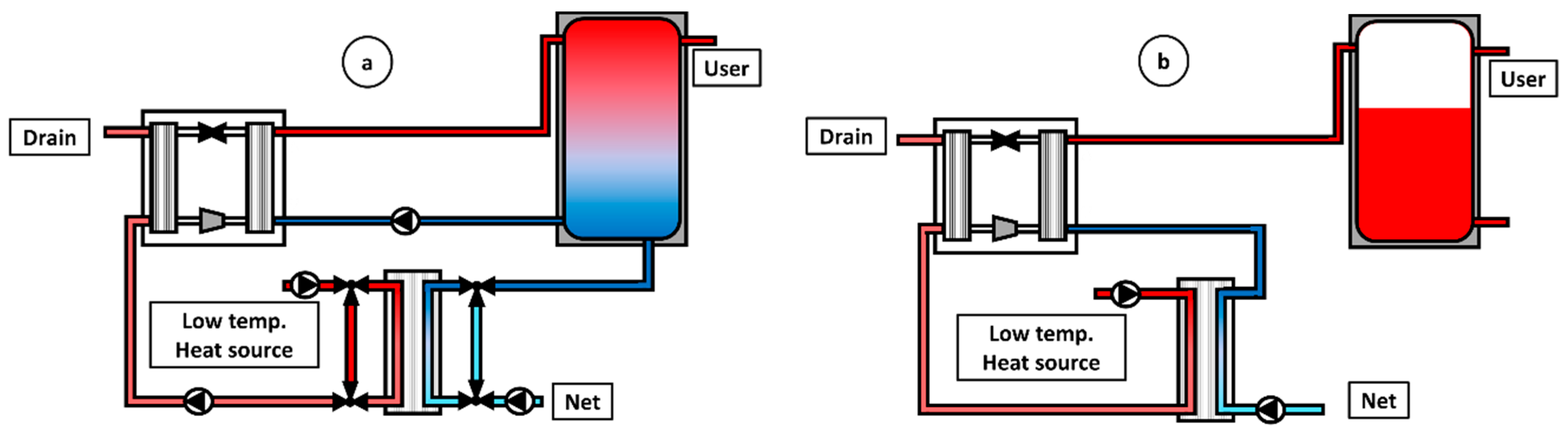
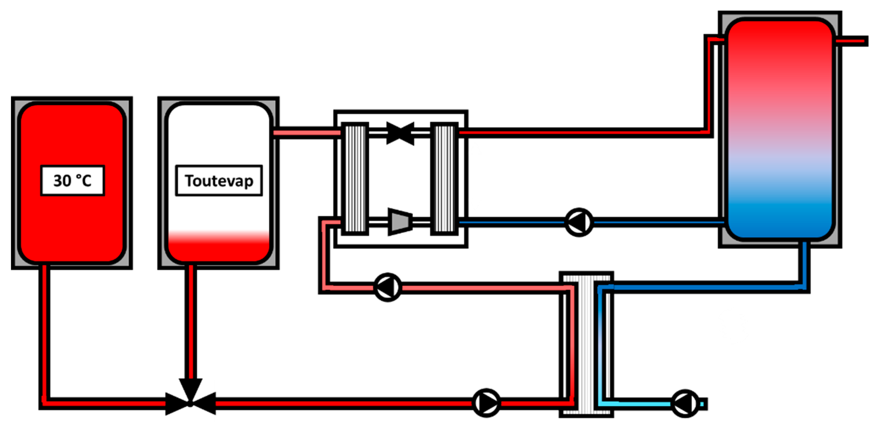
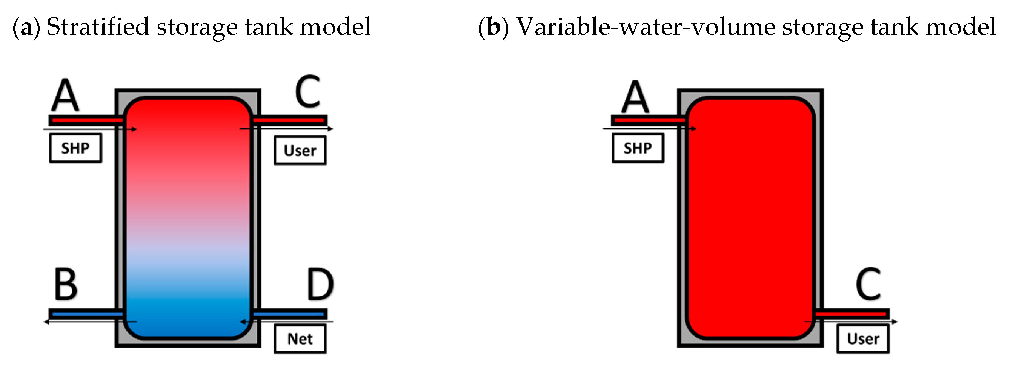
Figure 1a presents the general layout of the conventional solution, HP coupled with TES and HRU, with a stratified storage tank, whereas
Figure 1b presents the system with the variable-water-volume TES system proposed in [
31].
The systems under analysis consists of a HP-DHW production facility with sensible heat storage and a HRU. The main components of both systems are:
The HRU, which consists of a braze plate heat exchanger (BPHE) that takes profit of the temperature of the heat source to preheat the water coming from the net.
The thermal energy storage (TES) is a sensible heat storage tank. The two studied TES alternatives are a stratified storage tank (a) and a variable-water-volume storage tank with uniform temperature (b).
The booster HP that corresponds with the subcooled HP (SHP) developed under the EU project NxtHPG [
33], which is able to always work with optimal subcooling.
The circulation water pumps.
As it is possible to observe in
Figure 1, the topology of both cases is different. The variable-water-volume tank case includes the HRU between the water heat source loop and the SHP, whereas the stratified case includes it between the city water net and the tank. In the stratified tank case, it is very convenient to force the water passing through the recovering heat exchanger before entering the tank, since it will give the maximum recovery and will improve the efficiency of the stratification in the tank given that the temperature difference between top and bottom decreases. This layout is not possible in the case of the variable-water-volume tank since the tank has only one inlet, which must be kept at the maximum temperature.
The stratified tank topology has 2 inlets and two outlets and this implies that it has more variability in its operation as the SHP can be switched on but no fresh water is going into the tank (water tank heating) or fresh water can be flowing into the tank but the SHP can be off. These situations are not present in the variable-water-volume tank, as it only has one inlet and one outlet, and when there is fresh water flowing in the tank, the SHP and the BPHE must be active.
In order to perform a fair comparison between both cases, two different operation modes of the stratified case have been considered. Operation mode 1 includes a bypass to the HRU as shown in
Figure 1a. This responds to the fact that, in the variable-water-volume system, there is only preheating when the SHP is switched on and also when more heat is extracted from the water heat source in such a way that when the SHP is off and there is fresh water flowing into the tank no heat recovery is applied. This operation mode could be interesting from the point of view of saving heat source use in the situations in which its exploitation is low. Operation mode 2 consists of operating the system without any bypass. In this way, when the SHP is switched off but there exists user demand, a constant water mass flow is kept through the hot circuit of the HRU. This water heat source mass flow will be referred as MWOFF in the following, which means that the HRU is working, and the water entering the tank at the bottom is first heated up thanks to the heat recovery. The value MWOFF is a parameter of the system.
2.2. Integrated System Model
Transient system simulation tool (TRNSYS) [
34] has been used to model and analyze the different cases. The model presented in [
31] was used for the variable-water-volume case and the stratified model was created using the variable-water-volume model as basis. The features and modeling of the main components of the systems and of the control are commented in the following.
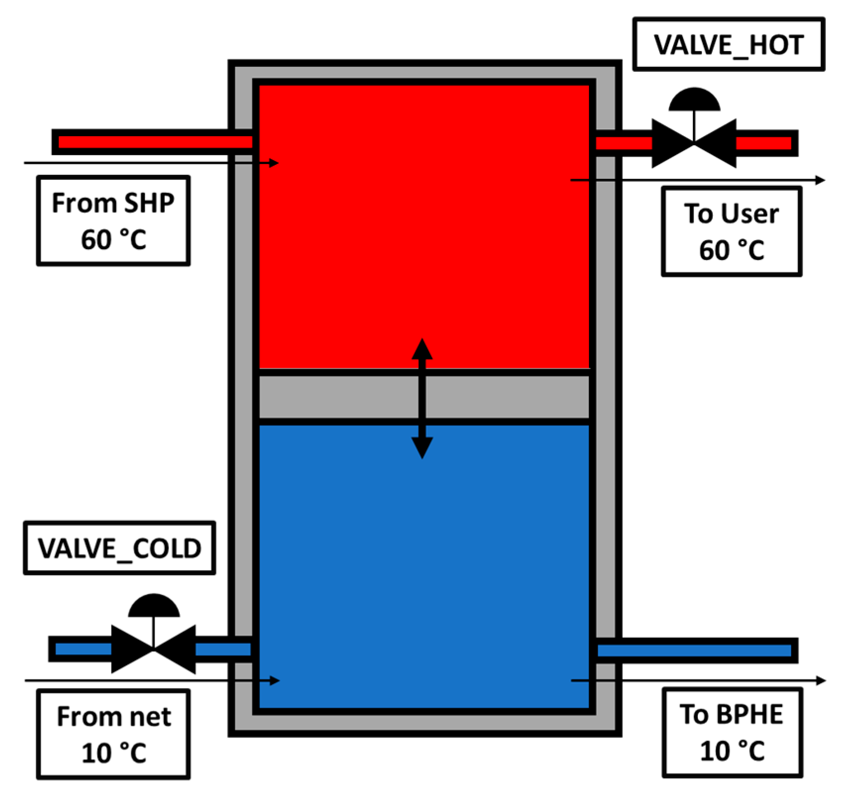
The stratified tank was simulated with TRNSYS type 60, whereas the variable-water-volume tank was simulated using TRNSYS type 39. The height of the inlets and outlets of the stratified tank were defined according to those of typical commercial tanks for that application: inlet to the tank from the SHP at 90% of the total height, the outlet of the tank to the SHP at 10%, the inlet to the tank from the net at 5%, and finally the outlet to the user at 95%. The variable-water-volume tank has only one inlet from the SHP and one outlet to the user. The peculiarities of the variable-water-volume tank model in comparison with the stratified tank, are that first the water temperature inside is considered uniform, although it is changing with time, depending on the mixing between the inlet flow coming from the SHP, and the outgoing flow going the user, and the heat losses to the ambient; and second, that the volume of water inside the tank is variable, depending on balance between the DHW production from of the SHP and the DHW demanded from the user.
Regarding the shape of the tanks, an aspect ratio of 4 was considered for both storage tanks. This value is usual in commercial tanks and commonly used in stratified storage tank models. A value of 0.8 W/m
2K was considered in accordance with the maximum heat loss coefficient allowed by Spanish regulation. Regarding the connection between the tank and the SHP, a direct connection has been considered in this study. The effects of an indirect connection could also be studied as it has been done in [
36].
The TRNSYS model of the stratified tank considers a de-stratification conductivity value that accounts for the conduction losses. TRNSYS mathematical reference recommends calculating this value by using Equation (1), the value obtained and used in the model accounts for 2 W/mK (See [
37,
38] for a detailed explanation of the calculation method):
where
is the thermal conductivity of the wall tank,
is the cross-sectional area of the tank wall, and
the one from the fluid in the tank.
• HRU
The BPHE was modeled with the NTU-effectiveness approach, considering an effectiveness of 0.75 in the nominal point. The characteristic UA value is evaluated at the nominal point and kept constant along the simulations. NTU varies depending on the actual instantaneous mass flow rates.
• Other components
The circulation pumps were modeled with TRNSYS type 742. The pressure losses in each circulation loop were considered negligible in comparison with the pressure drop across the heat exchangers. A correlation for water pressure drop across the HRU, the condenser, and evaporator was developed from the corresponding catalogue data. The model of the circulation pumps allowed the estimation of the circulation pumps consumption given the pressure drop in their respective loop.
The models also included an anti-scalding mixer valve with the net at the outlet of the tanks in order to keep the required 45 °C.
• User demand
The user demand profile chosen for the study consists of 20 multifamily houses with an average occupancy rate of 1.95 people per house. The profile used for the study was obtained with the tool DHWcalc [
39] and it is explained in detail in [
31].
Control
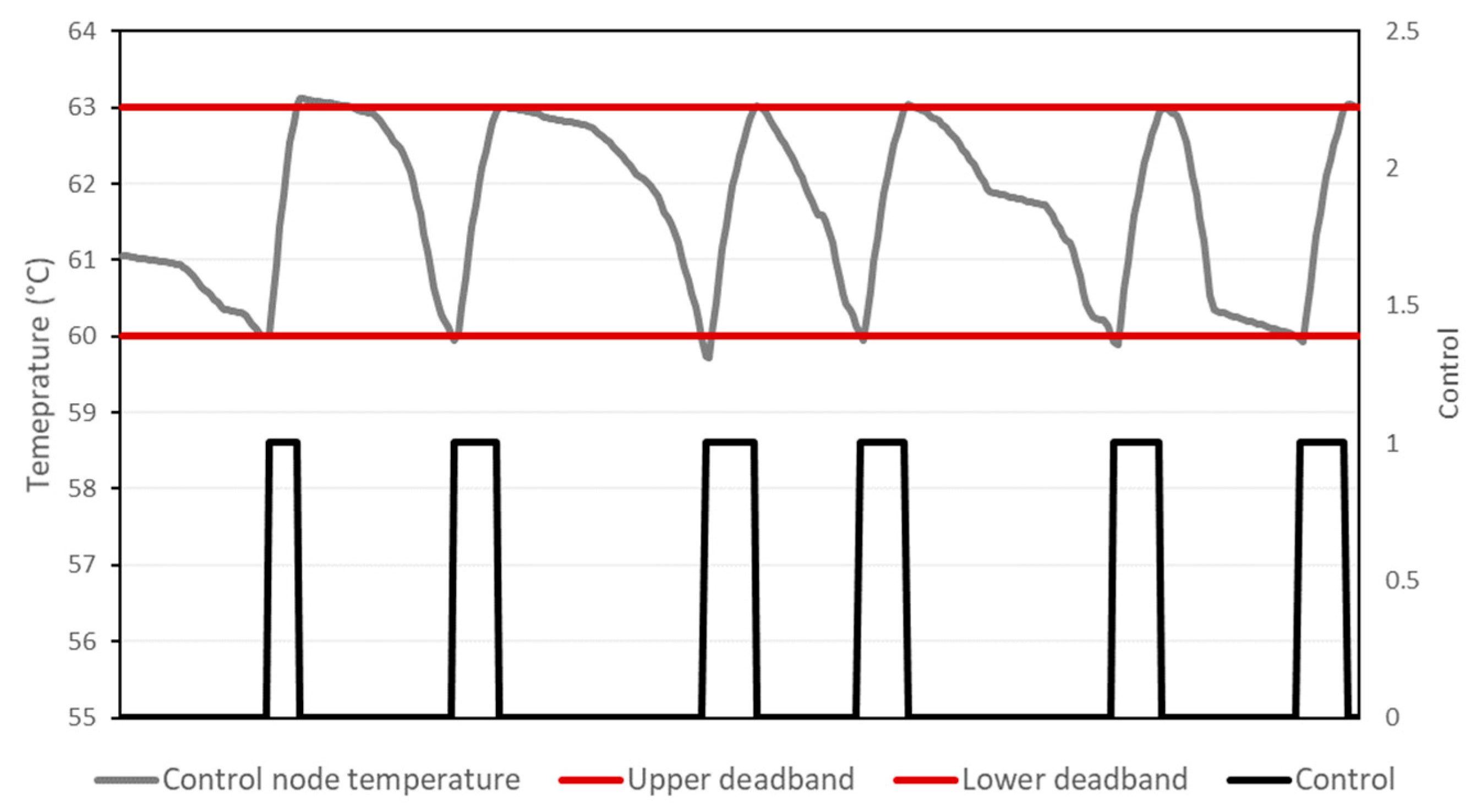
A different control strategy was followed in each case. The control of the stratified case consists of a temperature control that is performed through a hysteresis controller that commands the set-point temperature of 60 °C in the selected node of the storage tank. The upper dead band was fixed at 63 °C and the lower dead band is fixed at 60 °C, considering 60 °C as the minimum system temperature since the installation must satisfy the legionella regulation [
40].
Figure 2 represents graphically the operation of the hysteresis controller. In the upper part of the figure, the evolution of the temperature at the control node has been represented. As it can be observed, the temperature is well kept between 60 and 63 °C during operation. The position of the control of temperature in the tank is an important variable, therefore it was considered as an optimization variable.
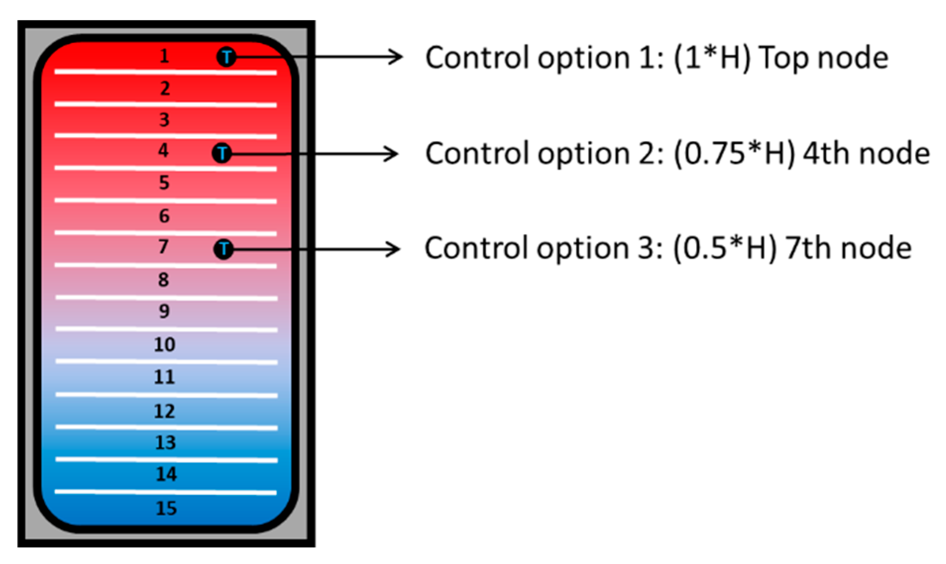
The tank model was composed of 15 levels, three variable levels were considered enough to study the influence of this parameter on the system performance: top node of the tank, fourth node from the top (75% of height), and seventh node (50% of height), as it is schematically shown in
Figure 3.
The water outlet temperature at the condenser was set to 63 °C. This responds to the fact of maintaining a minimum temperature in the tank of 60 °C, which is the control setpoint temperature. The simulations performed showed 63 °C as the minimum outlet condenser temperature that achieves this requirement stably.
However, the variable-water-volume case needs also to control the volume of water stored inside the tank, thus requiring a switch to stop the filling and the SHP use when the tank is full, and to fill in and switch on the SHP when the tank reaches a low level limit, which could lead to emptying the tank if the DHW demand follows. For this purpose, a parameter alpha defined as the percentage of the minimum volume inside tank, respect to the tank total volume, at which the SHP is switched on, was introduced in the model as an optimization variable.
2.3. Model Restrictions and Energy Performance Indicators
In order to compare the different systems, four indicators have been selected: the system global efficiency appointed as SPFuser (the system is designed to minimize this parameter), the SPF1, the total energy recovered at the BPHE, and the total energy used from the low temperature heat source:
The seasonal performance factor for the user () is defined as the ratio between the useful heat supplied to the user () and the total energy consumption of the system () as stated in Equation (2). The seasonal performance factor of the SHP () is defined as the ratio between the heat supplied by the SHP condenser () and the energy consumed by the SHP compressor ( as stated in Equation (3). Finally, the total energy recovered accounts for the energy recovered in the HRU and the total energy used from the low temperature heat source for the energy extracted from the heat source considering the minimum system temperature as reference (10 °C).
This study focuses on DHW production systems that employ a low temperature water stream as heat source, as for instance, grey water or a ULTDH. In order to reduce the number of input variables, the water temperature of the water stream has been considered as 30 °C and the temperature of the city water as 10 °C. Other combinations of temperatures could influence the absolute results but not the relative comparison among the options considered or the main conclusions.
Several restrictions have been added in the model in order to guarantee that all optimal solutions found also satisfy the user comfort (water supply at 45 °C) and the system reliability. The restrictions are:
Maximum value for the annual percentage of discomfort of 0.05%, evaluated as shown in Equation (4). Where
corresponds with the mass flow rate over 45 °C and
with the total mass flow rate:
The total amount of minutes along the year during which the comfort was not reached is limited to a maximum value of 30 min per year, which corresponds to 5 s of discomfort per day for each hour of the day. This value is quite small compared to comfort requirements imposed in other applications like heating and cooling of spaces in which total time percentages along the year are defined, but it should be done in that way as the demand profile along the day is quite focused in certain periods.
Limitation of the number of starts per hour of the SHP to a maximum of 9. This is the usual limitation stated by the compressor manufacturers.
2.4. Optimization Variables and Study
According to the main objective of the study: minimization of the energy consumption for a given DHW demand, the optimization variables selected for the study were the size of the HP and the volume of the tank; as well as, the position of the sensor in the stratified storage tank and the value of MWOFF if applicable, and finally, the parameter alpha for the variable-water-volume case. The levels of the variables, selected to perform the optimization study, are summarized in
Table 1. The percentage in the SHP size column indicates the percentage of the size considered in regard to a maximum considered size. The maximum values for the SHP size, the tank volume, the water flowrate MWOFF, and the ALPHA value were considered as 47 kW, 1000 L, 10,000 kg/h, 90%, respectively. The optimization study was performed for each case estimating the performance of the full factorial combination of parameter levels shown in
Table 1. Additionally, for the stratified tank case, the study covered each the following system options:
Without limitation in the water heat source.
Stratified with bypass.
Stratified without bypass.
Limitation in the water heat source.
Limitation on the energy recovered from the water heat source.
Limitation in the used amount of water heat source.
In the cases with the water heat source limitation, the limitation was fixed to the values obtained in the variable-water-volume case.
From the practical point of view, the cases in which there is no limitation in the availability of the heat source would correspond to a booster HP coupled with and ULTDH network. Whereas the cases with a limitation in the water heat source are more similar to an application such as grey water energy recovery since the use from the low temperature heat source is limited.
3. Results
This section has been divided in three parts. It should be remarked that there is no optimum solution but a pareto front of solutions that have a similar final minimum energy consumption. Therefore, the comparison among the different cases has been made for the solution with the minimum SHP size.
3.1. User Demand Profile Sensitivity Analysis
In order to be able to provide general conclusions of applicability, an analysis of the obtained results to the demand profile dependence was performed. The objective consisted of concluding whether the profile demand would influence the solution found.
To this purpose, different DHW demand profiles have been created using DHWcalc [
39]. These profiles are generated randomly but with a fixed value of liters/year. The simulations were performed for 10 years considering four different profiles, 3 of them were different, 1 year profiles repeated during the 10 years period, and the last one was composed of 10 year profile in which each year was different. The cases chosen are the optimal ones for the variable-water volume and the stratified case without bypass and without limitations.
Table 2 shows the results obtained for all the cases from the energy point of view, and it is seen that no significant differences are observed among the different cases, depending on the stochasticity associated to the DHW generation program. Therefore, the obtained system configurations and their associated energy consumption will not depend significantly on the stochasticity associated to the DHW demand.
3.2. Obtained Results for Each Case
This subsection presents the obtained results for the cases presented in
Table 1 in detail.
3.2.1. Variable-Water-Volume Case Results
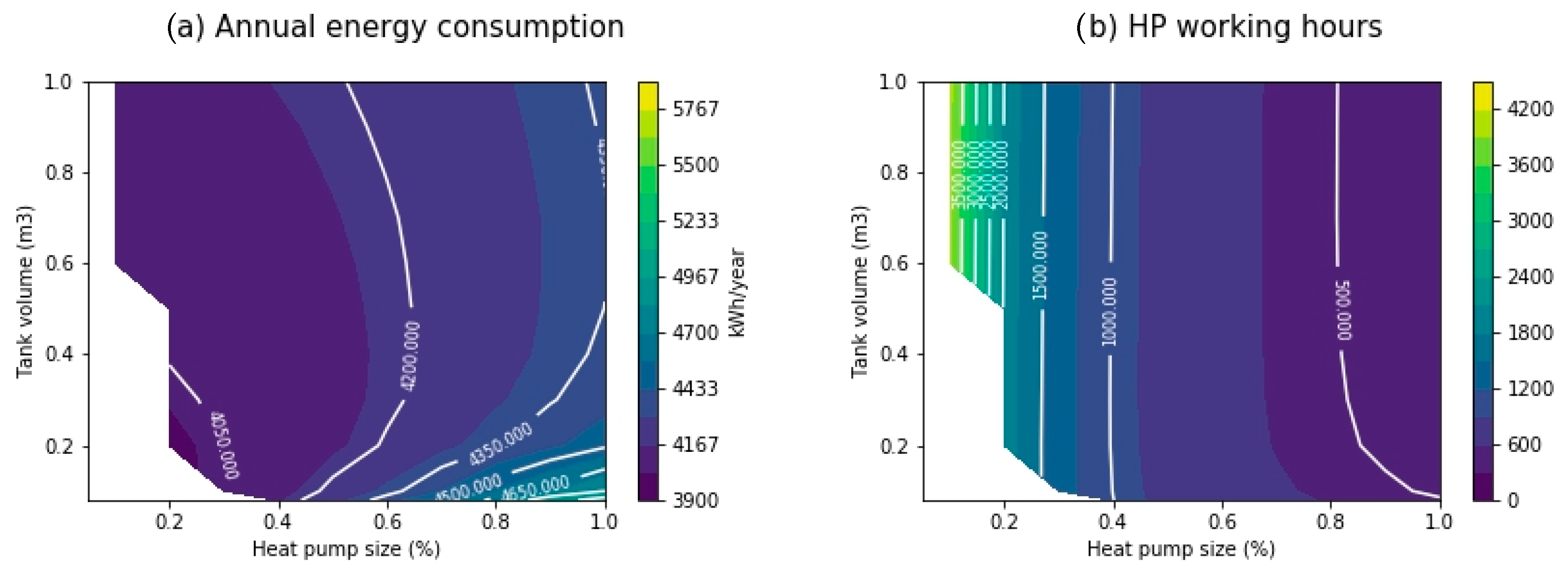
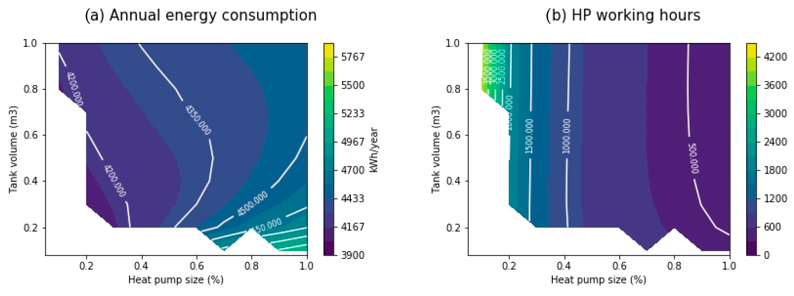
The results corresponding to the variable-water-volume case are presented in
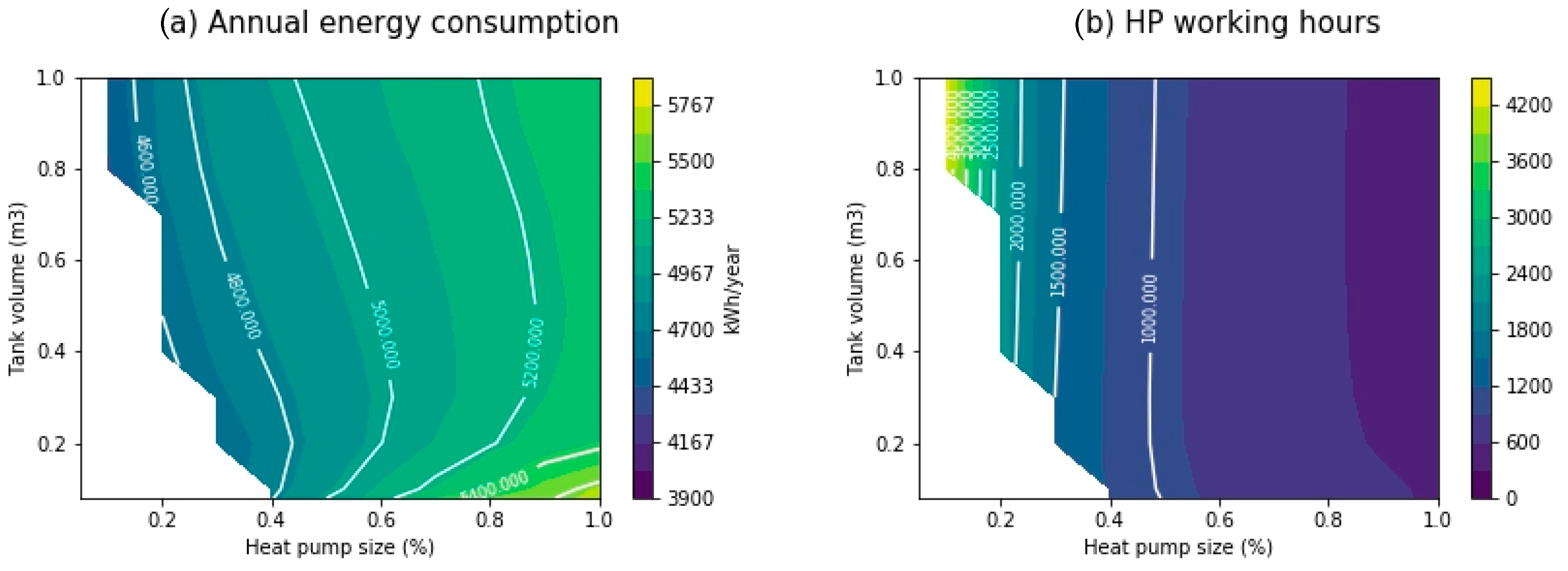
Figure 4. It shows the results for the different values of the optimization variables: SHP size and tank volume are illustrated in a map for the value of the optimization variable alpha of 0.4. The performance map for the annual energy consumption and the SHP working hours are included in
Figure 4. However, the rest of the maps for all the alpha values have been also considered for the conclusions here included.
As it has been commented, the results show that there does not exist a best case but a flat map of best cases with a reduced difference among them. The performance maps show the tendencies commented in the following:
The white region corresponds to SHP-volume combinations which do not satisfy the comfort criteria.
SHP size: the maximum system performance is reached for the low SHP sizes. However, the tank size should be also designed in agreement with it to minimize the energy consumption.
Tank volume do not have so much impact as the SHP in the energy consumption of the system.
When the SHP increases its size, the use of small tanks penalizes the efficiency of the system.
For each SHP size, exists an optimum tank volume for a fixed value of the parameter alpha. In that sense, for a given SHP size, the use of a tank smaller than the optimum will penalize more the system efficiency than the use of a tank larger than the optimum.
As the SHP size is reduced, the number of SHP operation hours increases, the tank volume has a limited influence on the working hours and for the same SHP size, this time increases slightly with the increase of the tank volume.
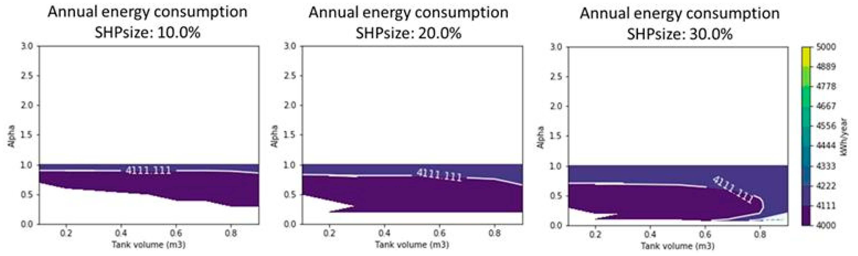
Alpha: This parameter affects the energy consumption indirectly. Although it does not have a major relevance in the total energy consumption (see
Figure 5), as its value increases, the minimum tank volume increases and in this way, more combinations of SHP-tank sizes are included in the cases that comply with comfort conditions. This fact allows to include as feasible solutions more cases with low SHP-tank sizes that usually correspond with the lowest energy consumption cases. Therefore, although alpha does not have a direct influence on the energy consumption, to select high alpha values allows to include in the possible configurations SHP-tank volumes smaller which tends to increase the efficiency of the system.
3.2.2. Stratified Case Results without Water Heat Source Limitation
Stratified Case Results with Bypass
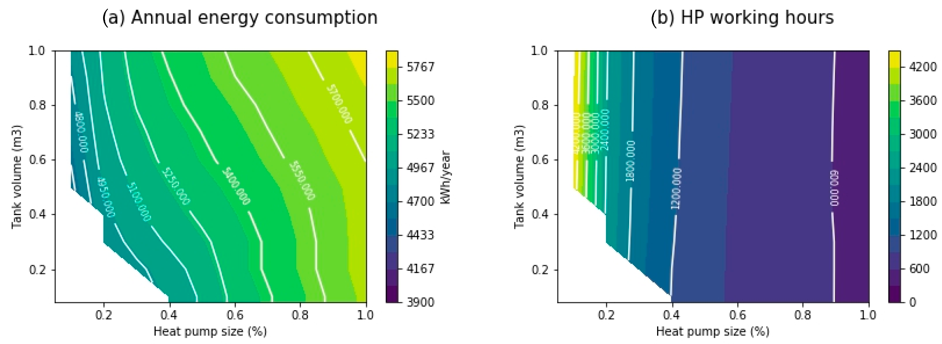
The results corresponding to the stratified case with bypass, considering that there is no energy recovery when the SHP is switched off, are presented in
Figure 6,
Figure 7 and
Figure 8. In them, the results for the different values of the optimization variables: SHP size and tank volume for the 1st, 4th, and 7th node, respectively, are illustrated. The performance map for the annual energy consumption and the SHP working hours are included for each case.
Similarly, to the variable-water-volume, the best results are obtained for the lowest values of SHP size dominates over the tank size from the energy consumption point of view, however in this case, the tank volume has a higher influence on the energy consumption of the system. Regarding the control node, the best results are obtained for the highest position. However, as low is the position of the control node in the tank, there are more SHP-tank combinations satisfying the comfort restrictions imposed to the problem. Thus, it is possible to conclude that the highest position for the control node is the optimal one but for these cases, the design of the system is more critical, as the allowed tank and SHP sizes are more restricted.
It is observed that the number of operating hours as well as the energy consumption of the system is significantly higher than in the variable-water-volume case. This is a consequence of the fact that in this system typology, there are operation modes in which the SHP is not working and therefore, water from the net is entering directly to the tank without any preheating. This has the advantage of saving heat source water, but on the other side, the energy consumption is penalized and the heat pump has to work more hours in such a way the water saving is not so important as expected.
Stratified Case Results without Bypass
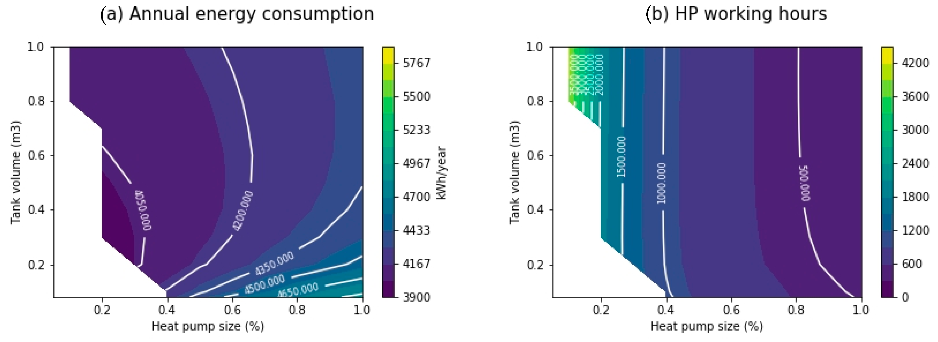
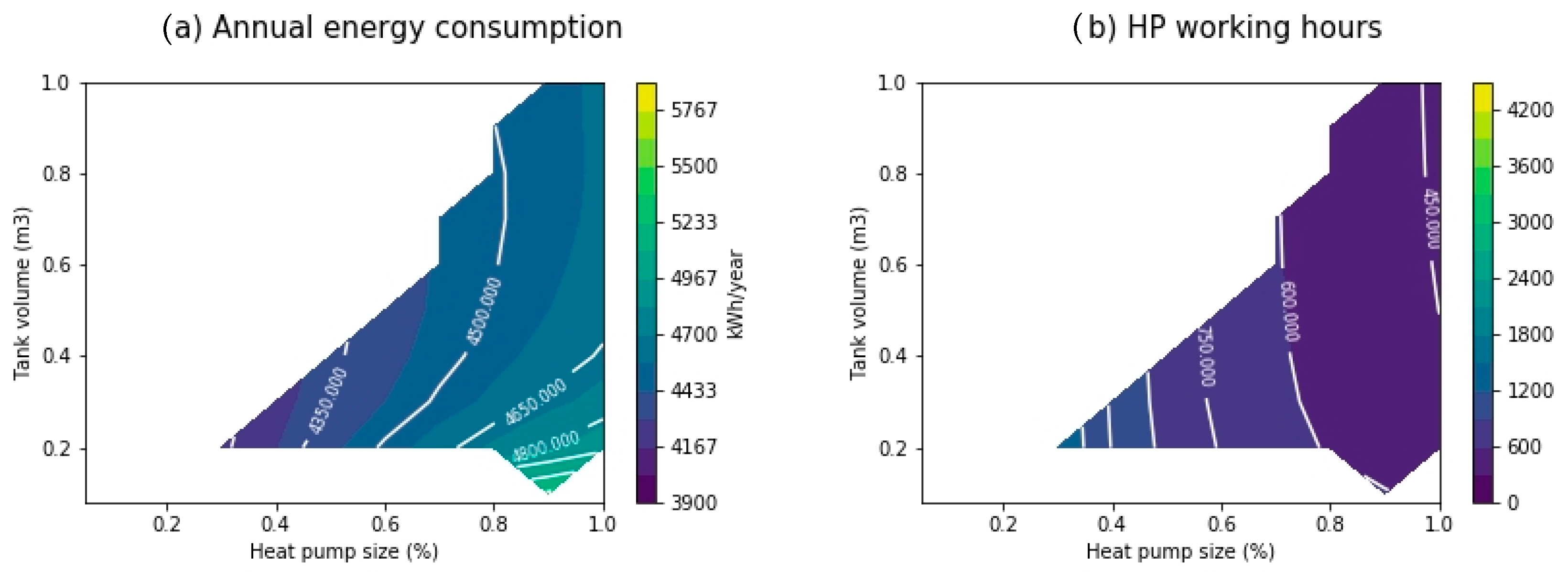
The results corresponding to the annual energy consumption and to the working hours are presented in
Figure 9 for the case in which the control is performed in the node 1 which corresponds to the higher efficiency, the results corresponding to the other node positions are not shown as the obtained trends are similar to the previous case.
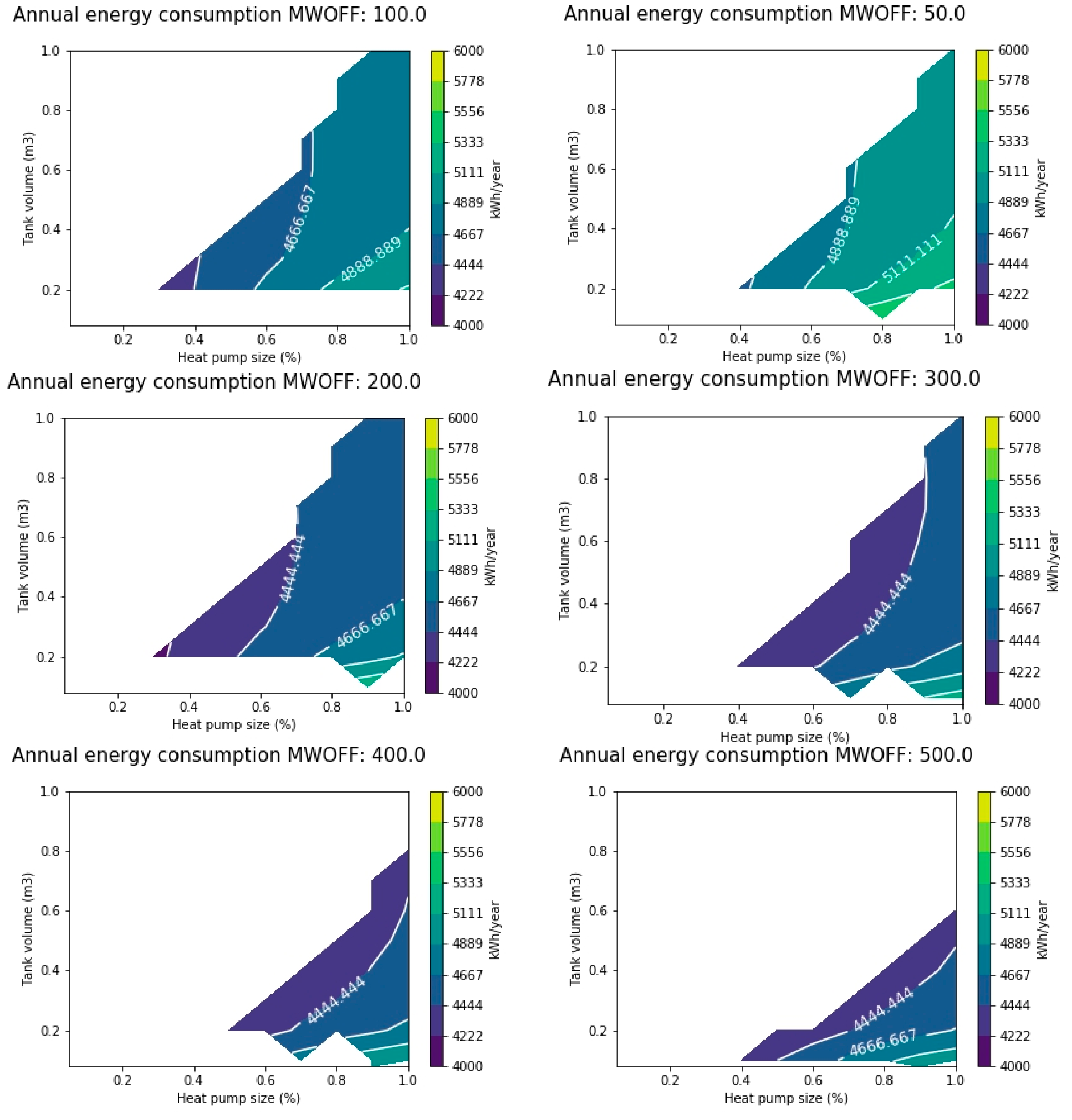
It should be noted that in this case, the mass flow rate (MWOFF) circulating through the recuperator when the SHP is off must be determined. As it is indicated in
Table 1, a parametric study about the influence of this value in the total energy consumption of the system has been performed and the results shown in
Figure 9 correspond to a MWOFF value of 2000 kg/h, which has been the optimum value obtained from the parametric study.
The results show similar trends to the variable-water-volume tank. The best results are obtained for the lowest values of SHP-tank size, however it is observed that for a given SHP size, the tank volume should be larger. Regarding the working hours of the SHP are similar to the variable-water-volume case. Concerning the MWOFF value, the system global efficiency increases as this value increases due to an increase on the energy recovered, but also the energy consumed from the circulation pumps increases. Thus, there exists an optimum around 2000 kg/h over which the energy recovered collapses but the energy consumption from the circulation pumps continues increasing. The best stratified case shows a 0.8% lower energy consumption compared with the variable-water-volume case but requires 87% more energy from the low temperature heat source.
In the next subsection, the energy from the low temperature heat source of the stratified tank systems is going to be limited to the values obtained for the variable-water-volume tank.
3.2.3. Stratified Case Results with Water Heat Source Limitation
For the limitation of water availability, two options have been analyzed. First, the same amount of energy recovered from low temperature heat source than in the variable-water-volume tank was imposed on the model. Later on, the use of the same amount of water was considered, in this case to simulate that behavior, the scheme shown in
Figure 10 was used. According to the results obtained previously, the bypass configuration is not going to be analyzed for these cases.
Limitation in the Energy Recovered by the System
The value at which the restriction was imposed is 88,060 kWh, which corresponds to the one required in the variable-water-volume case. In this way, the stratified cases with a higher energy use than the limited settled will be discarded.
Figure 11 represents the energy consumption as a function of SHP size and tank volume for several values of MWOFF. The results show that the annual energy consumption of the system increases until it reaches a value of 200 kg/h, maintaining the space area of possible configurations of SHP-tank size and later on, the energy consumption changes the trend with MWOFF and begins to decrease slowly with the increase of MWOFF. In addition, it is observed that the space area of possible system configurations is reduced.
Figure 12, the results for the annual energy consumption and the SHP working hours are represented. All these results have been presented for the best value of the optimization variable MWOFF (200 kg/h).
Regarding the observed trends, several comments can be done:
There is a significant reduction of the amount of system configurations (SHP-tank size able to satisfy the comfort requirements).
The size of the SHP required is larger than when there is no limitation in the energy source.
For a given SHP size, the range of water tanks compatible with the comfort requirements is reduced. This will imply that the system will be more sensible to design parameters.
For a given SHP size, the optimum tank volume is the smaller tank compatible with the comfort restrictions.
The value of MWOFF has been significantly reduced (approximately 200 kg/h).
With this limitation there is a total energy consumption increase of 5% compared to variable-water-volume case with the same energy use from the source.
The number of operating hours of the SHP has also increased compared to the previous case in which there was no limitation in the energy recovered from the water heat source.
Limitation Total Water Use of the System
In order to analyze the restriction on the low temperature heat source in such a way that the water mass flow is limited but not the energy use, the system configuration shown in
Figure 10 has been arranged. The daily water use from the low temperature heat source of the variable-water-volume case has been used as the daily limit. While this limit is not reached, it was considered to store the energy at the outlet of the evaporator of the SHP. In this way, when the daily limit is reached, the hot water network flow at 30 °C is stopped and the system could take the water from the tank where the outlet of the SHP evaporator has been stored instead of taking it from the network at 10 º C, as shown in
Figure 10.
In
Figure 13, the results for the annual energy consumption and SHP working hours has been represented as a function of the SHP-tank size for the MWOFF value of 300 kg/h.
Regarding the obtained results for this case, the following statements can be done:
The map of possible solutions is similar to the obtained for the stratified cases without any limitation in the heat source.
The total energy use from the water has increases in 10% compared to the variable-water-volume case.
The energy consumption in this case is higher than for the variable-water-volume case.
The number of working hours of the SHP is higher than for the variable-water-volume case.
3.3. Comparison Results
In this subsection, a comparison among the solutions for the different cases is presented.
Table 3 summarizes the obtained results for one specific solution in such a way that the comparison could be made in a clear way. The table includes the results of the optimization variables as well as the energy performance indicators selected (see
Section 2). Among the different values for the minimum energy consumption, the solution with the smaller SHP size is presented. In some cases, there are solutions in which the minimum SHP implies a significant increase of the tank volume, for those cases two different size alternatives have been presented.
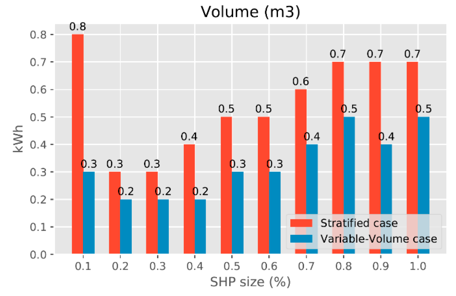
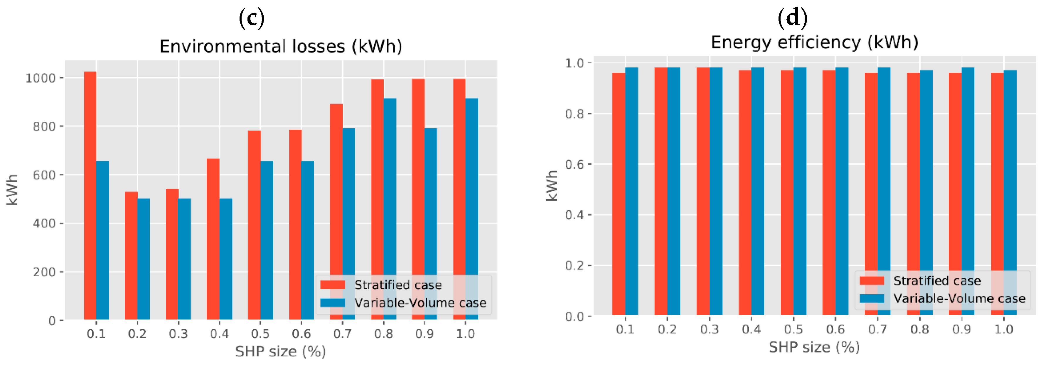
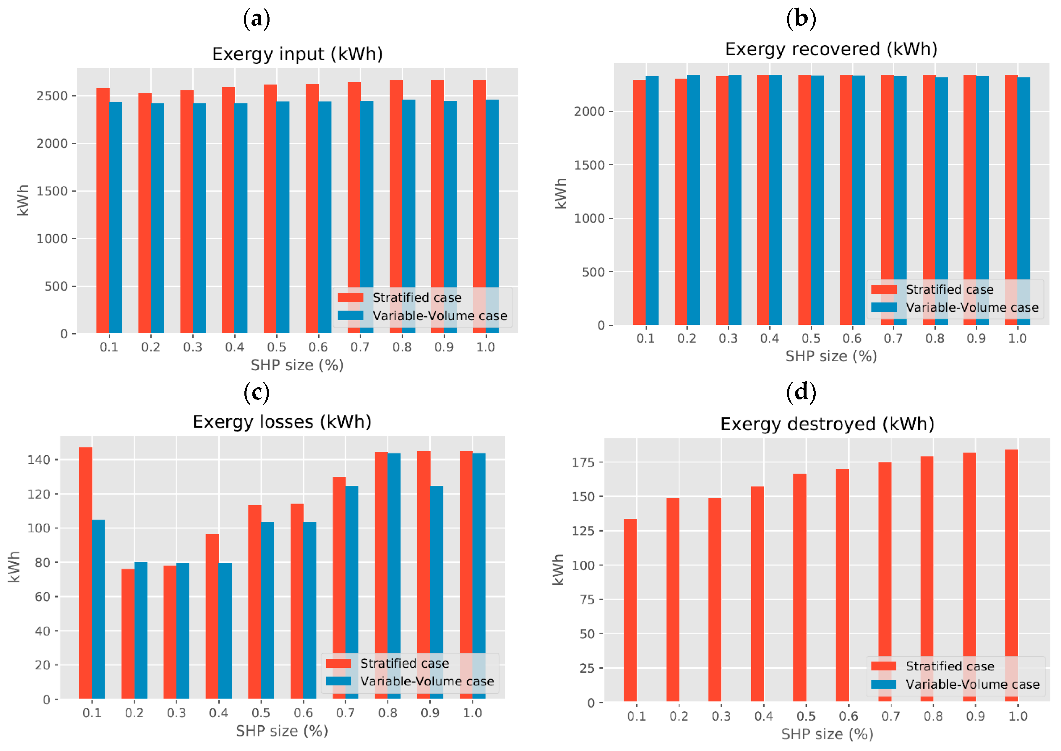
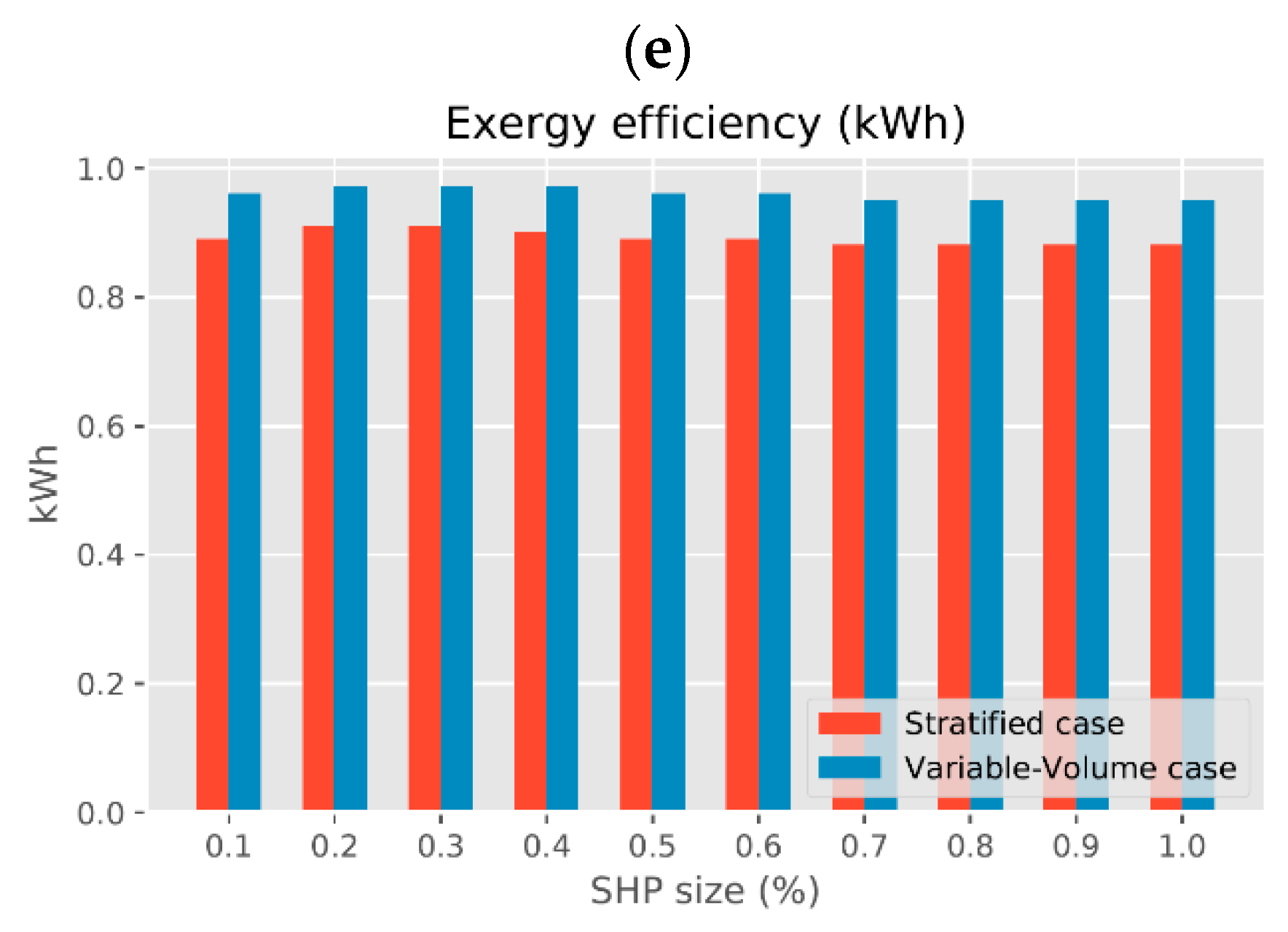
The comparison between the different cases shows that variable-water-volume tank requires a smaller system (tank and SHP) than stratified system. This is a consequence of the better energy storage strategy of this type of tank. A more detailed explanation about this point is found in the annex, where an energy and exergy analysis of both tank configurations have been done. In that analysis, it is demonstrated that although the energy content of both tanks is similar, the exergy of the variable-water-volume tank is significantly higher (8%), allowing a volume reduction of it. For the calculated cases, the variable-water-volume tank requires half the volume of the stratified tank and the SHP can work with 33% lower capacity.
From the point of view of energy efficiency, when the by-pass is present, the reduction in the energy efficiency of the system is very significant, and as the SHP is working for a longer time period, the amount of used heat water source is also higher than in the stratified cases, therefore from these results it can be concluded that the water has be to preheated before entering in the tank in all the situations. The stratified tank requires significantly higher amount of low temperature heat from the source (87%) than the variable-water-volume tank in order to have a similar efficiency.
For the same energy use from the low temperature heat source, the stratified system with the proper control has a reduction in energy efficiency of 3.6% compared to the variable-water-volume tank. This difference can be reduced to almost 2% but in that case, 10% more of energy from the water heat source must be used.
Considering that the results with unlimited availability of water from the low temperature energy source could correspond with an ULTDH application, the stratified case shows a slightly better system global efficiency. This could put the stratified case as the best option from the energetic point of view for a booster HP application with the ULTDH network. However, the energy use from the ULTDH network is 87% higher. Considering the cases in which a limitation is imposed, its function can be linked to a grey water energy recovery application since a limited daily grey water production is fixed. In this case, it can be concluded that the variable-water-volume case is a better option for a booster HP application with grey water energy recovery. In conclusion, the variable-water-volume case is the best option for a booster HP with energy recovery (ULTDH or grey water) from a low temperature heat source since it achieves the maximum system global efficiency with a much more reduced energy use from the source and lower heat pump and tank sizes.
5. Conclusions
The research work presented in this paper includes the analysis of the influence of the TES system coupled with a HP for an energy recovery application. Two alternatives of the TES system have been studied and compared: the conventional stratified storage tank and the innovative variable-water-volume storage tank. The study compares both systems from a system global energy performance perspective and to complement the conclusions an exergy analysis was also conducted.
The main results obtained show:
Variable-water-volume tank has shown an improvement in SPFuser of 3.5% compared to the stratified system for the same water use.
In the stratified tank, the HRU must be used always in order to preheat the water going into the tank from the net.
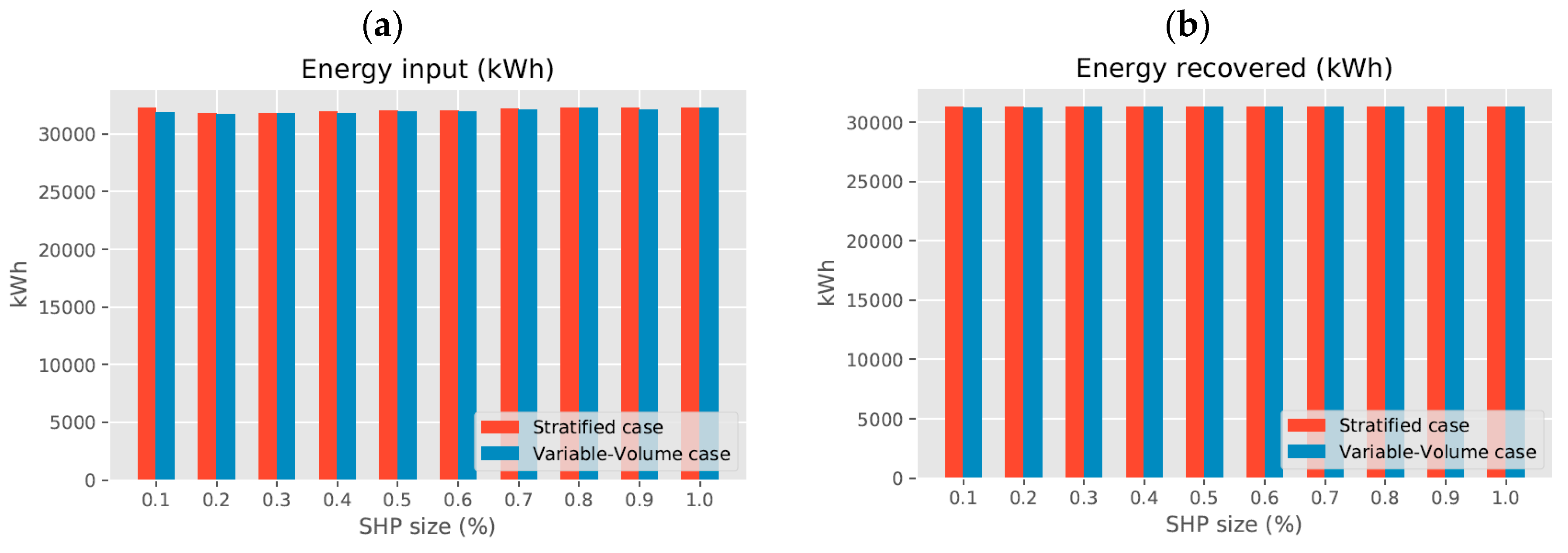
The stratified system uses less efficiently the energy input, requiring a significantly higher amount of energy input in order to be able to achieve similar SPFuser. The difference is critical in waste heat energy recovery applications where the amount of available energy is limited.
A significantly smaller SHP-tank size from the variable-water-volume case when compared with the stratified case (half the tank size and 33% of SHP size), which will be due to a reduced system cost. This point is a consequence of the higher exergy efficiency due to the exergy destroyed in the stratified case by the dead water volume.
The variable-water-volume case is the best option for a booster HP with energy recovery from a low temperature heat source, ULTDH network and especially grey water network, application since it allows the system to work with the highest system global efficiency and lowest energy use from the heat source.
It is worth mentioning that in all the studies performed in the current work, as in the most of theoretical studies available in the literature, the stratification of the storage tank is not disturbed by the water ingoing or outgoing from the tank. Therefore, the penalty of using stratified tanks would be higher in real systems. In that direction, the experimental test in a pilot plant in which tank temperature is registered will supply more insight about the real losses of stratified systems and how they can be compared with variable volume ones.
Regarding the variable volume tank, this work has assumed that the system is properly designed and working during the whole year, but if the variable volume tank is oversized, some stratification phenomena could appear that must be analyzed and their impact on the storage system evaluated, but it is out of the scope of this work and this effect as well as the stratification breaking in stratified tanks will be the object of a future research.
In conclusion, the variable-water-volume case has shown to be a better option to be coupled with HP technology regarding heat recovery applications over the conventional stratified case. With a higher energy recovered rate and higher exergy efficiency that led to achieve lower SHP-sizes and simpler configuration circuit considering the same energy demand. Finally, a practical way to implement the water storage tank with the corresponding operation strategy has been proposed, showing that the idea could be implemented without increasing significantly the system cost.


