Article

Modeling and Design of a Multi-Tubular Packed-Bed Reactor for Methanol Steam Reforming over a Cu/ZnO/Al2O3 Catalyst

Department of Energy Technology, Aalborg University, Pontoppidanstræde 111, 9220 Aalborg Ø, Denmark
*
Author to whom correspondence should be addressed.
Submission received: 6 December 2019 / Revised: 24 January 2020 / Accepted: 26 January 2020 / Published: 31 January 2020
(This article belongs to the Special Issue Fuel Cell Systems Design and Control)

Abstract

:
Methanol as a hydrogen carrier can be reformed with steam over Cu/ZnO/Al2O3 catalysts. In this paper a comprehensive pseudo-homogenous model of a multi-tubular packed-bed reformer has been developed to investigate the impact of operating conditions and geometric parameters on its performance. A kinetic Langmuir-Hinshelwood model of the methanol steam reforming process was proposed. In addition to the kinetic model, the pressure drop and the mass and heat transfer phenomena along the reactor were taken into account. This model was verified by a dynamic model in the platform of ASPEN. The diffusion effect inside catalyst particles was also estimated and accounted for by the effectiveness factor. The simulation results showed axial temperature profiles in both tube and shell side with different operating conditions. Moreover, the lower flow rate of liquid fuel and higher inlet temperature of thermal air led to a lower concentration of residual methanol, but also a higher concentration of generated CO from the reformer exit. The choices of operating conditions were limited to ensure a tolerable concentration of methanol and CO in H2-rich gas for feeding into a high temperature polymer electrolyte membrane fuel cell (HT-PEMFC) stack. With fixed catalyst load, the increase of tube number and decrease of tube diameter improved the methanol conversion, but also increased the CO concentration in reformed gas. In addition, increasing the number of baffle plates in the shell side increased the methanol conversion and the CO concentration.

1. Introduction

The contribution of hydrogen to the promotion of green energy is mainly driven by recent achievements, especially polymer electrolyte membrane (PEM) fuel cells, where hydrogen is used as the fuel. One obstacle for the development of the hydrogen economy is the safe storage and transportation challenge presented by hydrogen. Therefore, special attention has been paid to the development of economical hydrogen production methods by chemically converting hydrocarbons or alcohols to a hydrogen-rich synthesis gas stream. This process, generically called reforming, requires oxidizing agents. When water is used as the oxidant, the process is known as steam reforming [1]. Among various hydrogen carriers, methanol stands out because of its properties of being liquid at ambient conditions and infinitely miscible with water. Moreover, methanol has a low boiling point (65 °C) for vaporization, a relatively high H/C ratio (4:1), a low reforming temperature (200–300 °C) owing to the absence of a strong C–C bond, and is producible from various carbon-based feedstocks, such as natural gas, biomass, and CO2 [2,3,
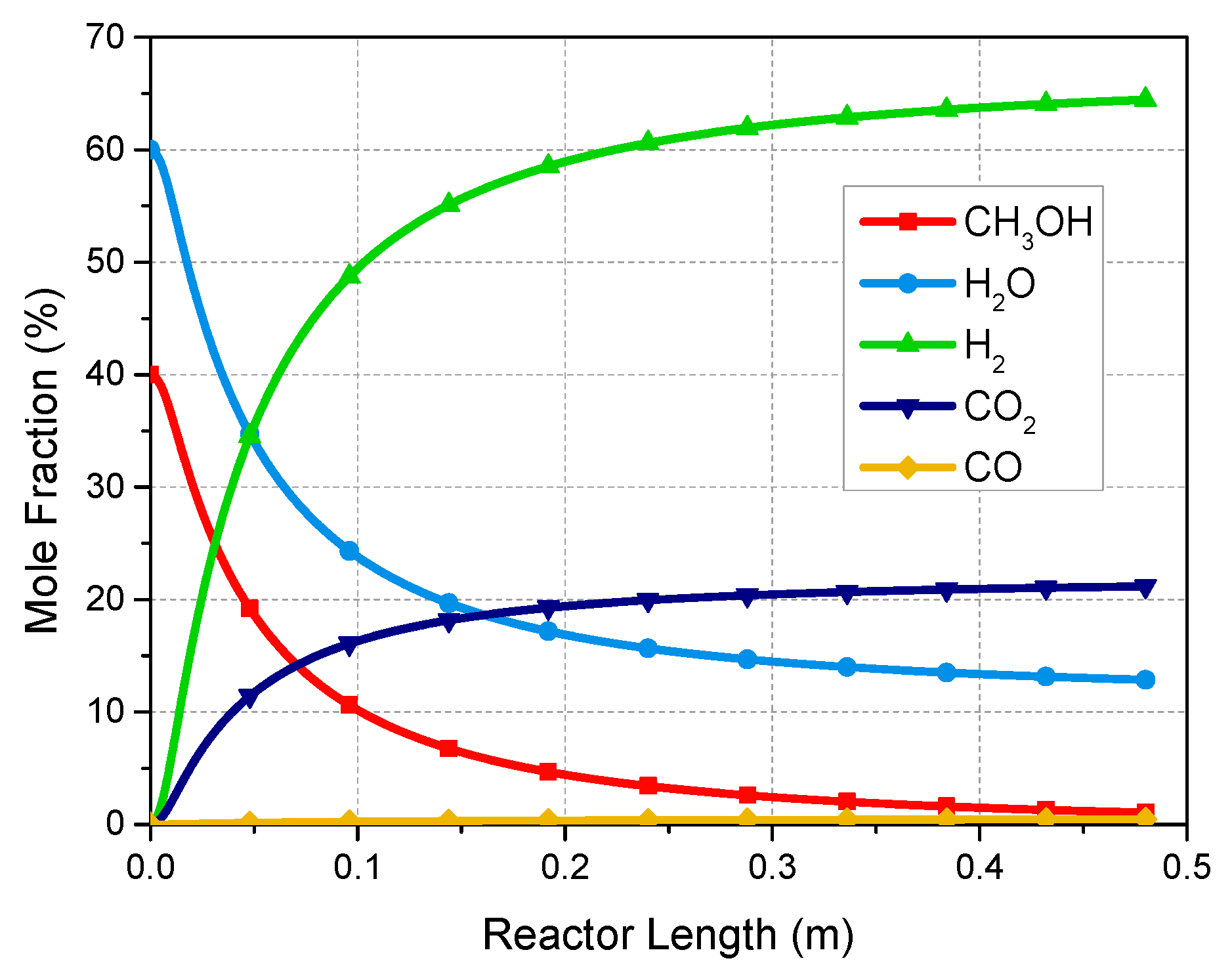
4]. Under appropriate conditions, the most favored reaction stoichiometry is the methanol steam reforming (MSR) reaction. One of the major advantages of the MSR reaction is that 1/3 of the hydrogen product can be derived from water. In addition to the MSR reaction, there are normally other two reactions that happen during the reforming process: the water-gas shift (WGS) reaction and the methanol decomposition (MD) reaction. The three main reactions that take place within the methanol steam reformer are shown in the following equations [5]:
Methanol steam reforming reaction (MSR):
CH 3 OH   +   H 2 O     CO 2   +   3 H 2 Δ H   =   +   49.7   ( kJ   mol 1 ) ,
Water-gas shift reaction (WGS):
CO   +   H 2 O     CO 2   +   H 2 Δ H   =     41.2   ( kJ   mol 1 ) ,
Methanol decomposition reaction (MD):
CH 3 OH     CO   +   2 H 2 Δ H   =   +   90.2   ( kJ   mol 1 ) ,
Although hydrogen is the only desired product, other by-products are inevitably formed in reformate gas mixture, such as carbon dioxide (CO2), small amounts of carbon monoxide (CO), unconverted water and methanol vapor. The fractions of methanol, CO2 and especially CO in the reformate gas should be minimized because of their poisoning effect on fuel cells [6,7]. Catalysts used for methanol steam reforming are supposed to have as main properties good activity and fast kinetics at low temperature, high selectivity to suppress CO production, good stability and long lifetime [5]. The most widely used commercial catalysts for the MSR process are Cu-based catalysts, especially Cu/ZnO/Al2O3, due to their relatively high activity and selectivity [8].
Methanol reforming methods carried out experimentally and industrially in packed-bed reactors will inevitably result in high investment and operating costs. Therefore, there are numerous studies on the kinetics and mechanisms of MSR over commercial Cu/ZnO/Al2O3 catalysts. Jiang et al. [9] proposed an expression of reaction rates based on power rate law kinetics. It is assumed that there was only one kind of active site for reactions and the methyl formate was the intermediate. Peppley et al. [10] studied the reaction network of MSR on the catalyst BASF K3-110. They assumed two distinct types of active sites, one type for MSR and WGS reactions and the other for MD reaction. And a comprehensive kinetic model was developed considering the surface mechanism of the catalyst. Agrell et al. [11] investigated the MSR over a Cu/ZnO/Al2O3 catalyst from Süd-Chemie (G-66 MR) and developed a kinetic model. With operating temperatures below 220 °C, an Arrhenius-type function was used; and with higher temperatures, the mass transport hindered the reaction kinetics, hence a fifth degree polynomial was used instead of the Arrhenius expression. Sandra et al. [12] and Herdem et al. [13] compared several kinetic rate expressions of the MSR process. They found that a kinetic Langmuir-Hinshelwood model which was developed by Peppley et al. [10] presented the best fit to the experimental data.
Another dominant factor for the reforming process is the reformer design. Conventional packed-bed reformers use catalyst particles in the form of pellets or cylinders, which are versatile for application at both the laboratory and industrial scale owing to their relatively low cost and easy operation [14]. Nevertheless, one disadvantage of packed-bed reformers is the radial temperature gradient in the catalyst bed [3]. Recent progress in micro-processing make it possible to manufacture wall-coated micro-channel reactors and membrane reactors, which present fewer heat and mass transfer limitations, less pressure drop, better selectivity, but also a drawback of lower specific catalyst load [2,9,15,16]. However, potential barriers for the commercialization of micro-channel and membrane reactors, such as high costs and low mechanical resistance, make packed-bed reformers still the most widely used types in the chemical industry for extracting hydrogen from methanol.
Because of the endothermic characteristic of the reforming process, an external heating source is needed to activate the reaction sites and prevent temperature drops in the catalyst bed. For on-site applications, it means that the reformer should be integrated with a heat supply unit, usually called a catalytic combustor or burner [17,18,19]. In this system, a flow of thermal fluid is needed to transfer heat from the burner to the catalyst bed. Reaction rates of methanol reforming predominately depend on the local concentration and temperature correlated to heat and mass transfer mechanisms, which should be investigated when designing a reactor. Yoon et al. [20] analyzed the dominant limiting mechanisms (heat transfer, mass transfer and chemical kinetics) in the methanol steam reformer theoretically and experimentally. Results showed that with the diminishing of catalyst size, the heat transfer limitation increased and the mass transfer limitation decreased. Also with the diameter of the reactor diminished, the heat and mass transfer were enhanced. Vadlamudi et al. [21] analyzed a packed-bed reactor for autothermal reforming of methanol to produce sufficient hydrogen for a 100 W fuel cell stack. They developed a 1-D non-isothermal model considering the steady state mass and energy balance. The simulated results agreed well with experimental data and the pressure drop was considered to be negligible. Ma et al. [22] investigated the hydrogen output and thermal behavior of a plant-scale fixed-bed reformer for methanol steam reforming based on a 2-D pseudo-homogenous model. The results showed that there was no obvious concentration gradients in the radial direction. Moreover, with a larger tube diameter, the limited heat transfer would lead to a larger radial temperature gradient in the catalyst bed. A similar result has been reported in [23] that the small ratio of tube to particle diameter ( D / d p ) and low reactant velocity introduced a large heat transport resistance between the tube wall and the catalyst particles. Mears et al. [23] developed a criterion to evaluate the importance of radial temperature gradients in fixed bed catalytic reactors. Results showed that the heat transfer resistance between the wall and the catalyst bed cannot be neglected when D / d p > 100 . Furthermore, the increased porosity of the bed near the wall caused a limited number of contact points between catalyst particles and the reactor wall. Hence, the major cause of the heat transport resistance between the catalyst bed and the reactor wall could be regarded as the gas film [24], which has been considered in this study. Vázquez et al. [25] employed a tubular-quartz reactor and a multichannel micro packed-bed reactor to perform the kinetic model of methanol steam reforming. The results represented both axial and radial temperature gradients in the catalyst bed. But for a small-scale multichannel reactor with a large length to width ratio ( L / W = 50 ), the radial temperature gradients in the catalyst bed can be considered negligible at an almost isothermal condition. The study proved that convective heat transfer properties in the catalyst bed could be improved by increasing the length to width ratio of reactors to increase the gas velocity and the contact surface of gas flow in reactors. Montebelli et al. [26] compared the performance of two highly conductive structured multi-tubular reactors with a commercial multi-tubular packed-bed reactor for methanol synthesis. They concluded that the packed-bed reactor had a better performance than structured systems due to the effective convective heat transfer mechanism in the catalyst bed, which is shown as lower hot-spot temperatures and higher radial heat transfer rates. The effectiveness factor for catalysts in commercial size has been widely investigated owing to the strong effect of internal diffusion on reaction rates. Lee et al. [27] estimated the effectiveness factor of catalyst particles to investigate the effect of the particle internal diffusion limitations and obtain the intrinsic kinetics of methanol steam reforming over Cu/ZnO/Al2O3 catalyst. Tesser et al. [28] tested different kinetics of steam reforming of methanol in packed bed reactor, considering both mass and heat balance along the length of reactor and inside the catalyst particles.
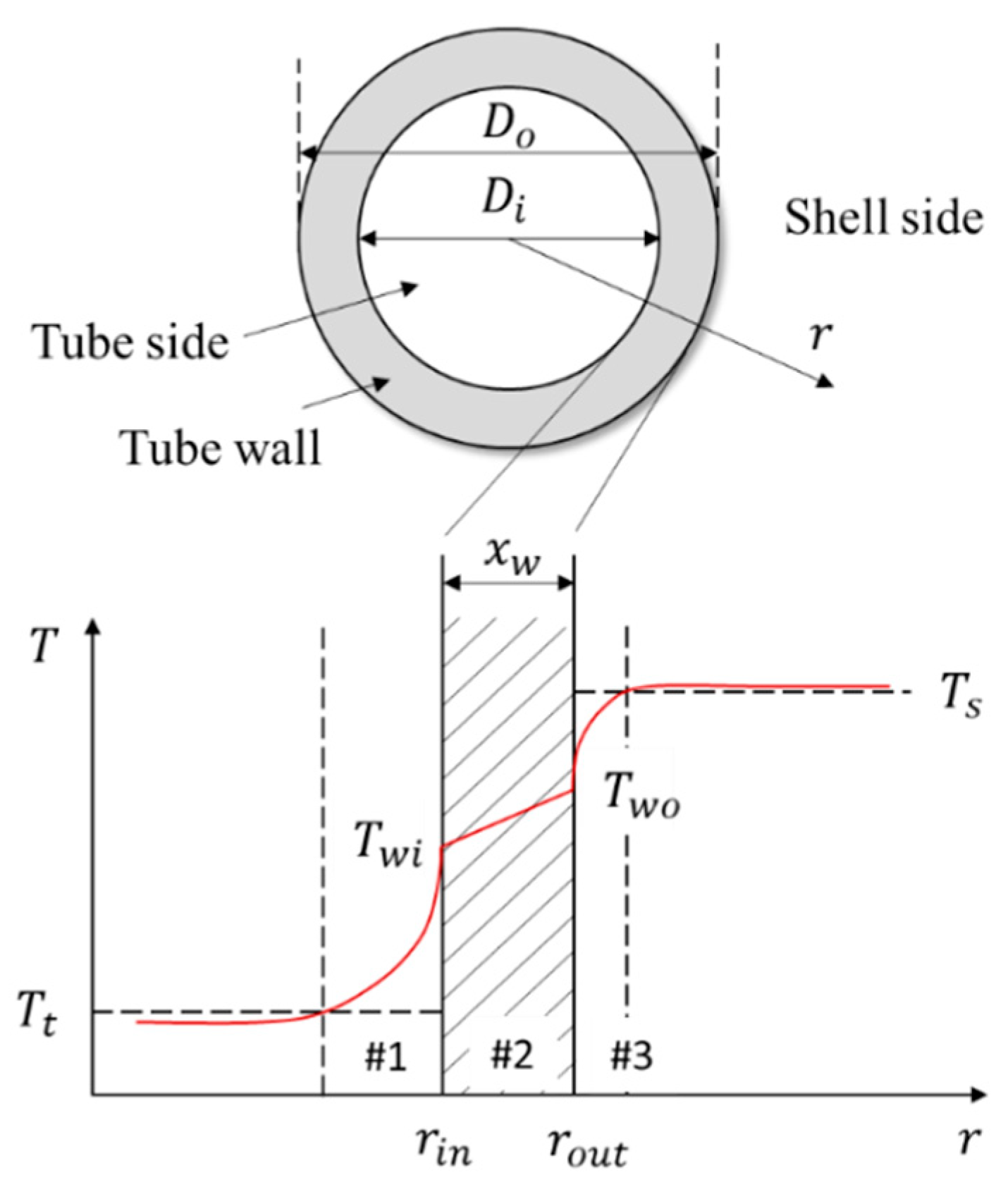
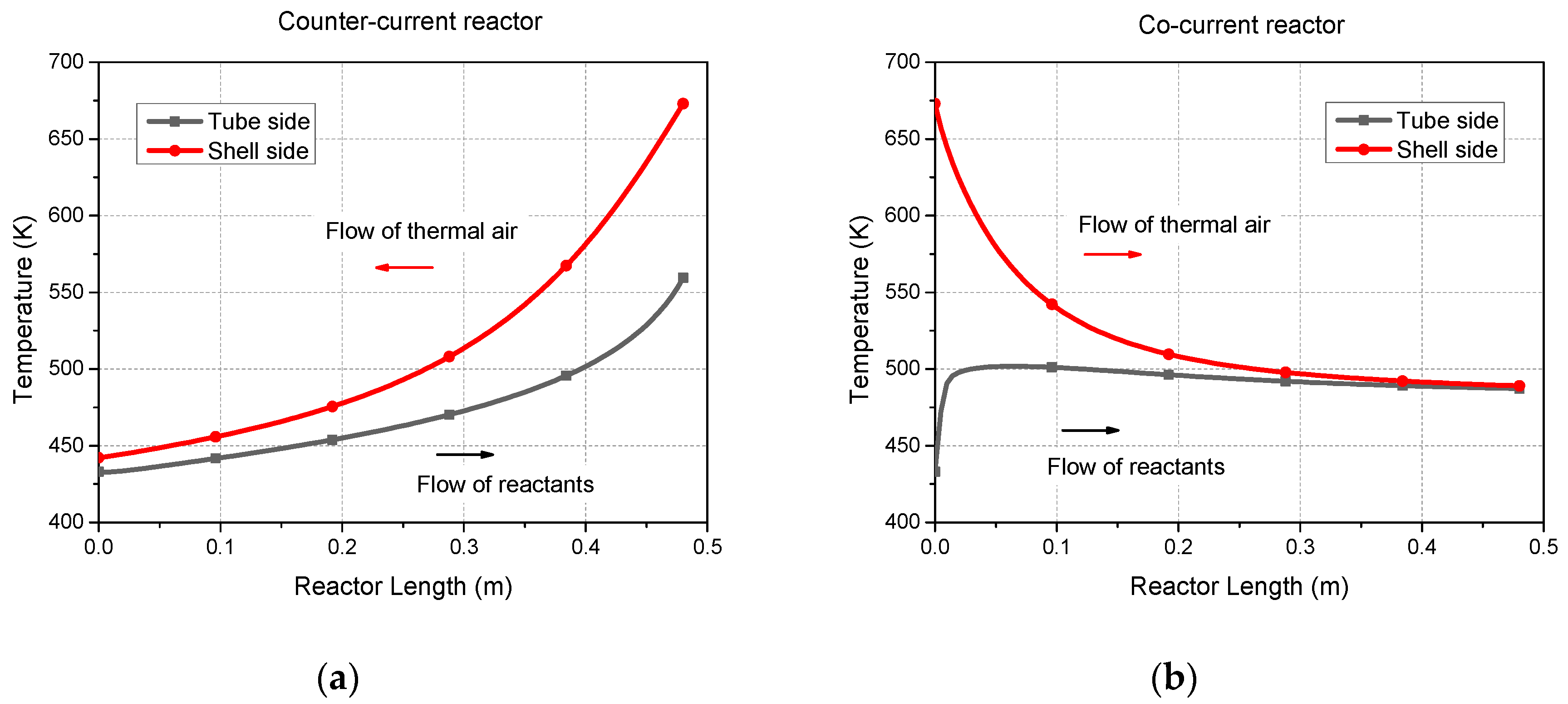
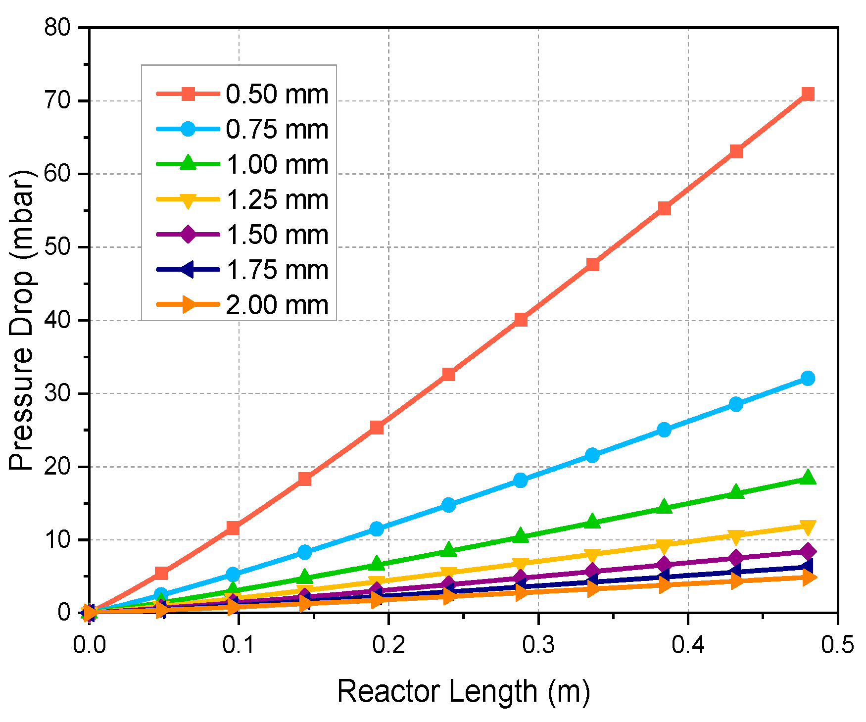
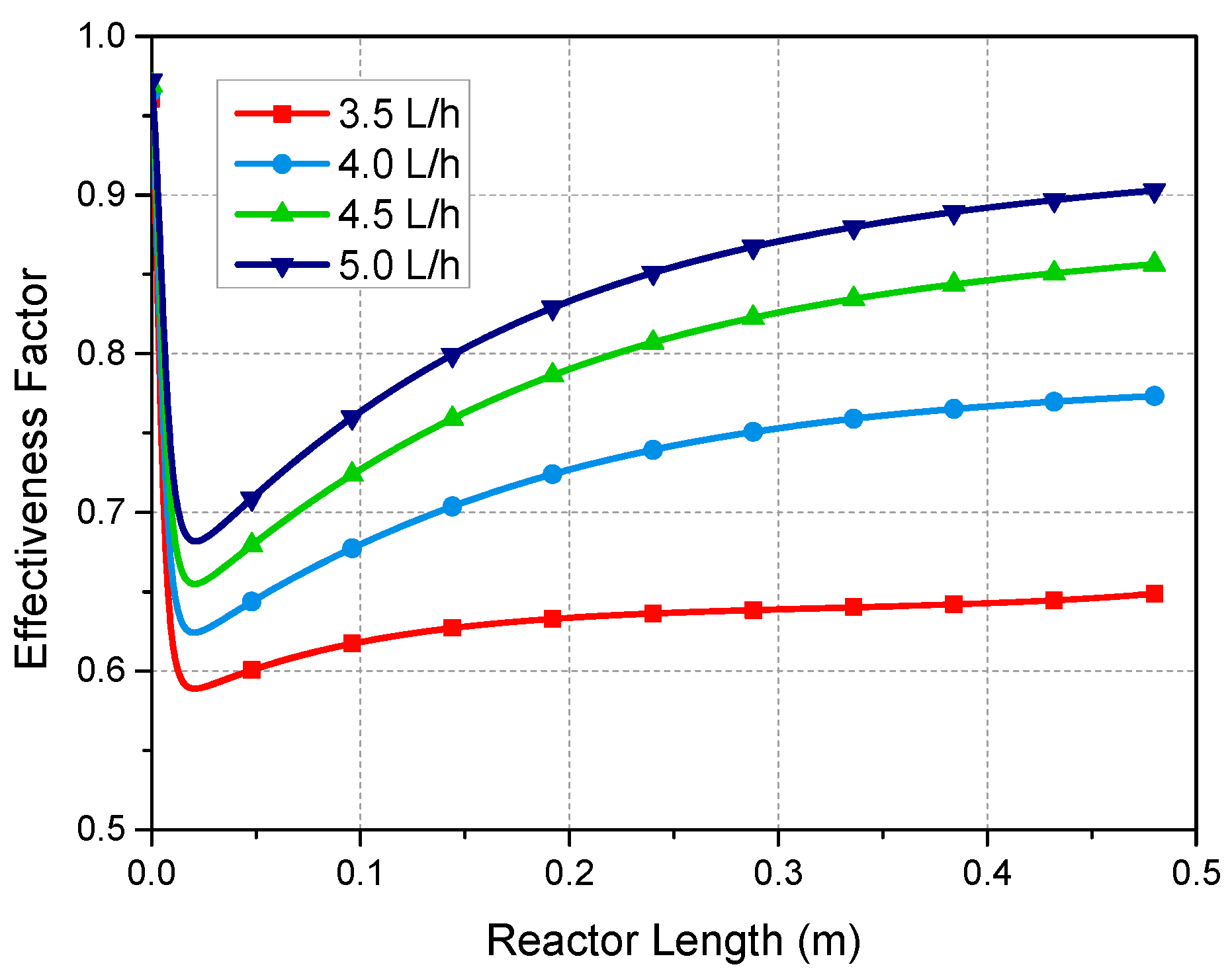
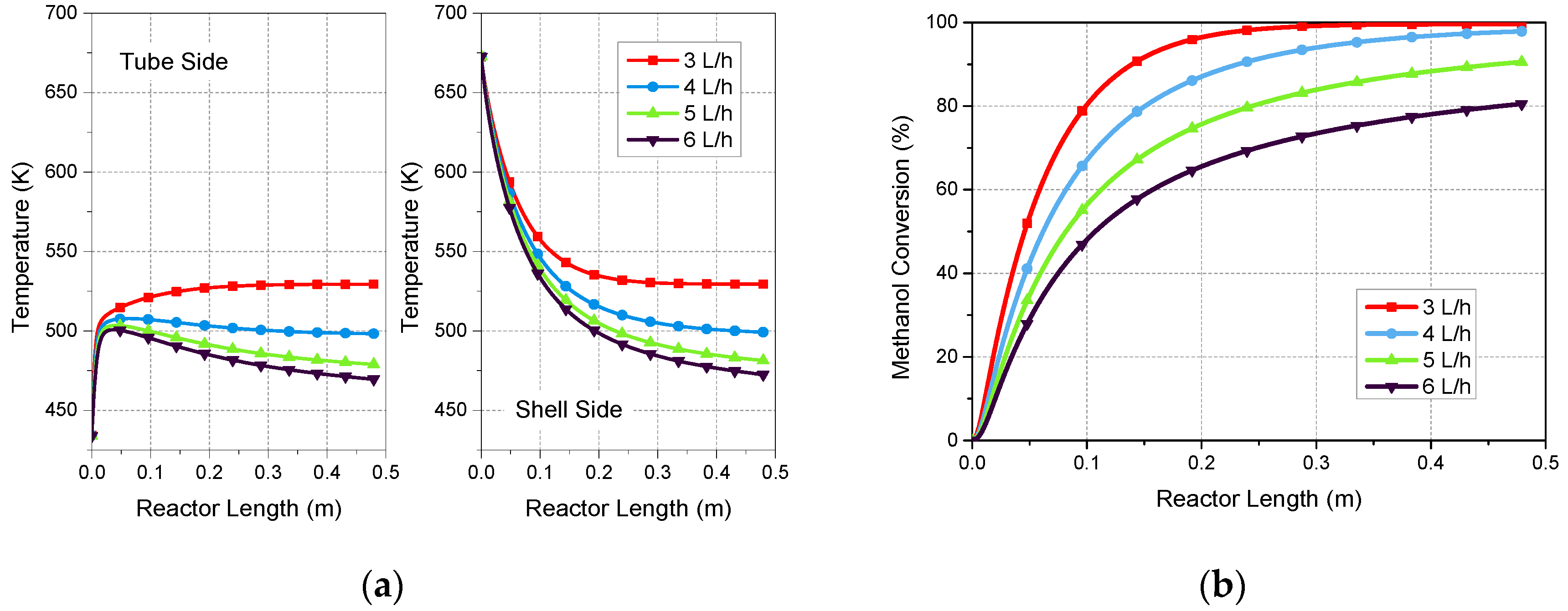
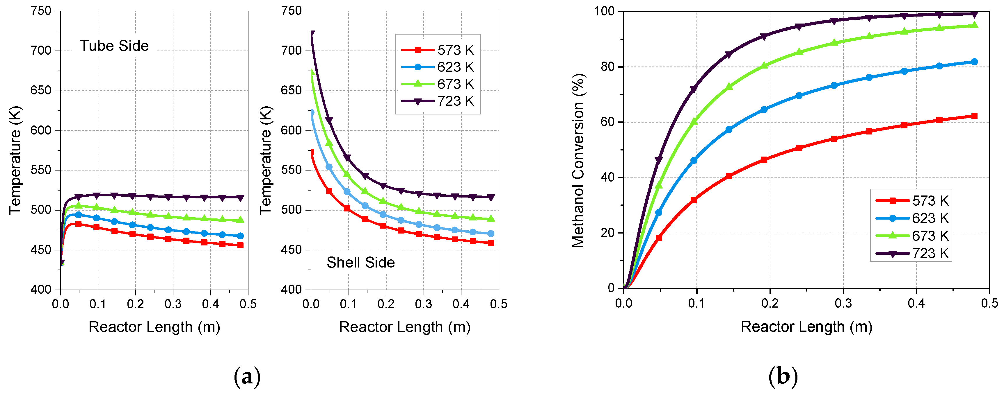
The multi-tubular packed-bed reformer is normally represented as an entire tube bundle immersed in an external heating source with a uniform and constant temperature when developing a mathematical model. However, in practical applications, the temperature of thermal fluid in inter-tubular space is variable along the length and has significant effect on the performance of the reformer. Therefore, the temperature profiles of both tube side and shell side along the reactor should be taken into consideration. Compared to the large heat transfer resistance between the tube wall and the catalyst bed, the convective and conductive heat transfer inside the catalyst bed is relatively efficient. Hence, with a large L/W of the reactor, we took into account the heat transfer resistance of gas film, and neglected the radial temperature gradient inside catalyst bed to simplify the model. The catalyst effectiveness factor is generally introduced for taking into account the internal diffusion resistance in commercial catalyst particles, especially when large size particles are used. In this paper, the Weisz-Prater Criterion was used to check if there were diffusion limitations, and the effectiveness factor was estimated for the reaction.
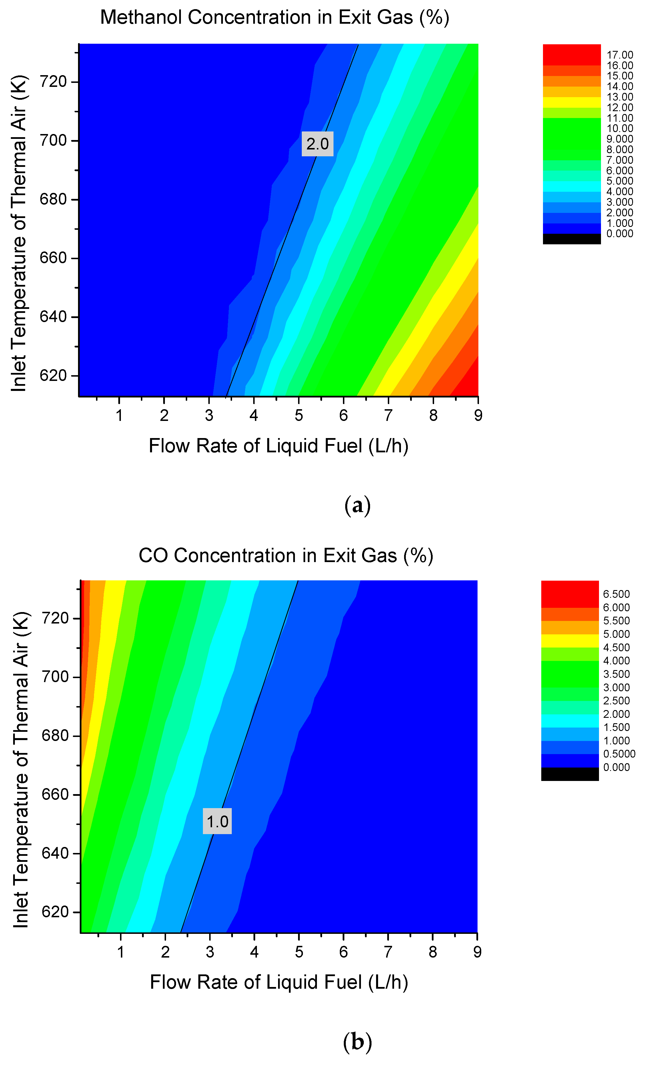
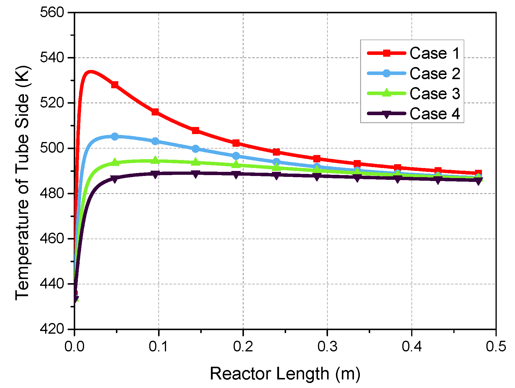
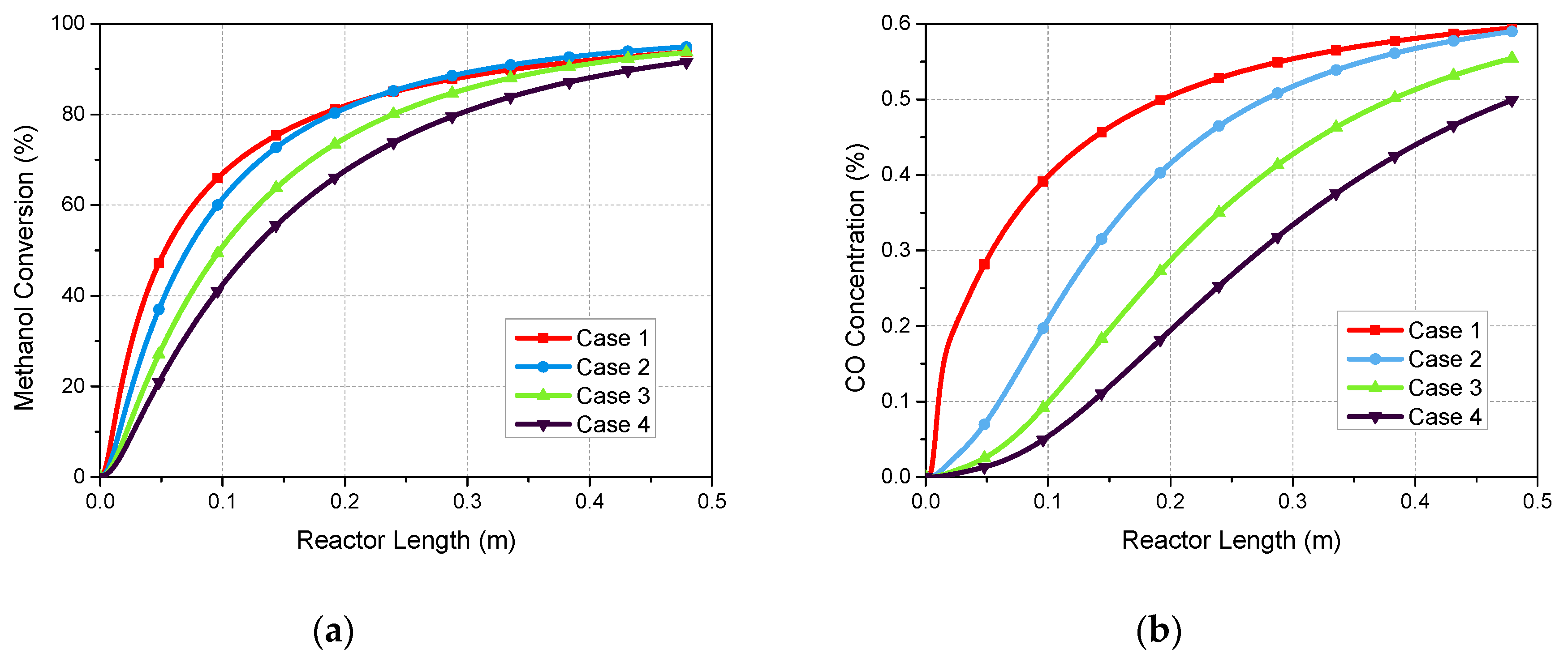
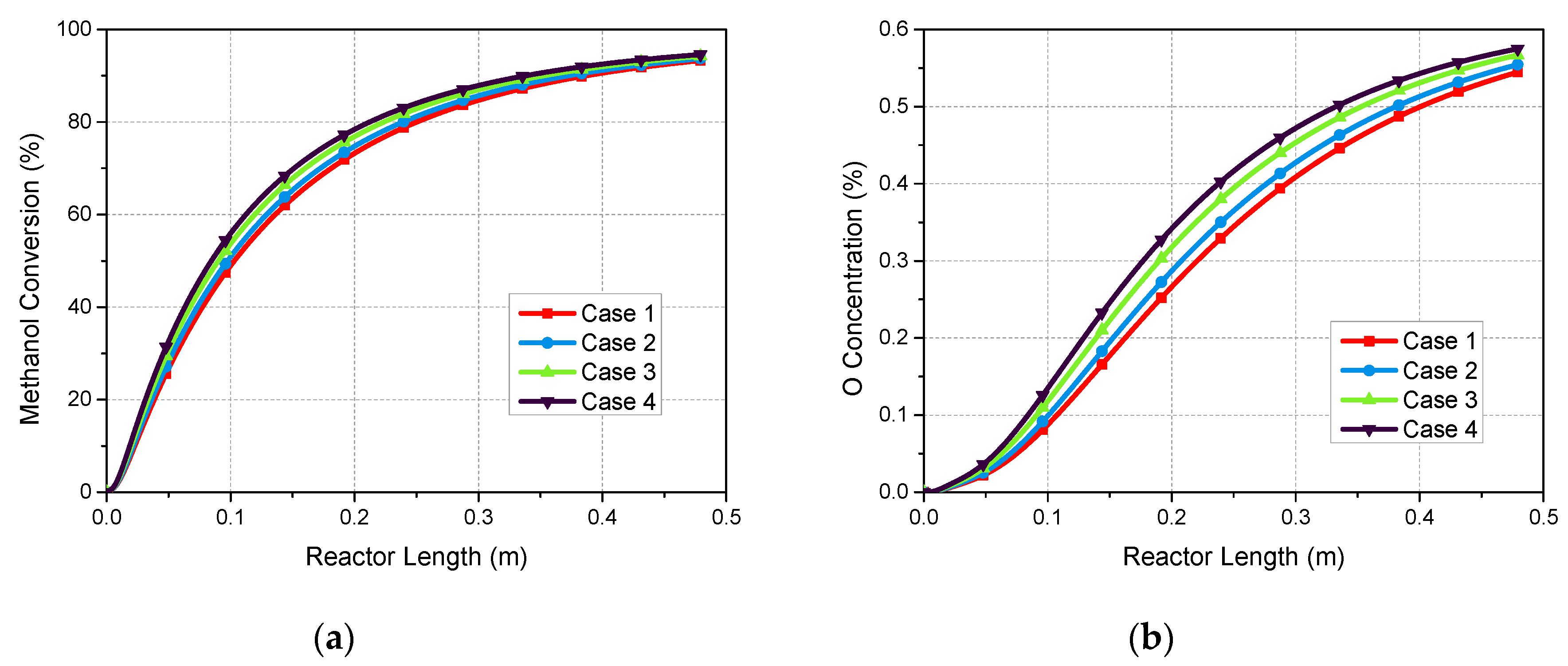
In this work, a one-dimensional pseudo-homogenous model for multi-tubular packed-bed reformer was established in MATLAB taking into account the main chemical reactions, and the mass and heat transfer phenomena in both tube side and shell side. In the radial direction, the overall heat transfer coefficient between catalyst bed and external heating source was considered, including the conductive heat transfer through the tube wall, the convective heat transfer from reactant to the inner wall of the tube, and the convective heat transfer from the outer tube wall to the outside fluid. Effects of the pressure drop along the reactor and the intraparticle diffusion limitation were also included in this model. A dynamic model of the multi-tubular methanol steam reformer was developed in ASPEN to verify the MATLAB model. The thermal behavior of both tube side and shell side was represented in the term of temperature profile. The influence of operating conditions such as flow rate of methanol-and-water mixture and inlet temperature of external thermal air on the methanol conversion and CO concentration of reformed gas was investigated. In addition, the impact of geometric parameters of reactor design, such as the diameter and number of tubes as well as the spacing and number of baffles, has been investigated on the reformer performance. This model of MSR is expected to be integrated with the high temperature polymer electrolyte membrane fuel cell (HT-PEMFC) in a combined stack arrangement to investigate the thermal integration of the system for further study.

2. Description of Methanol Steam Reformer

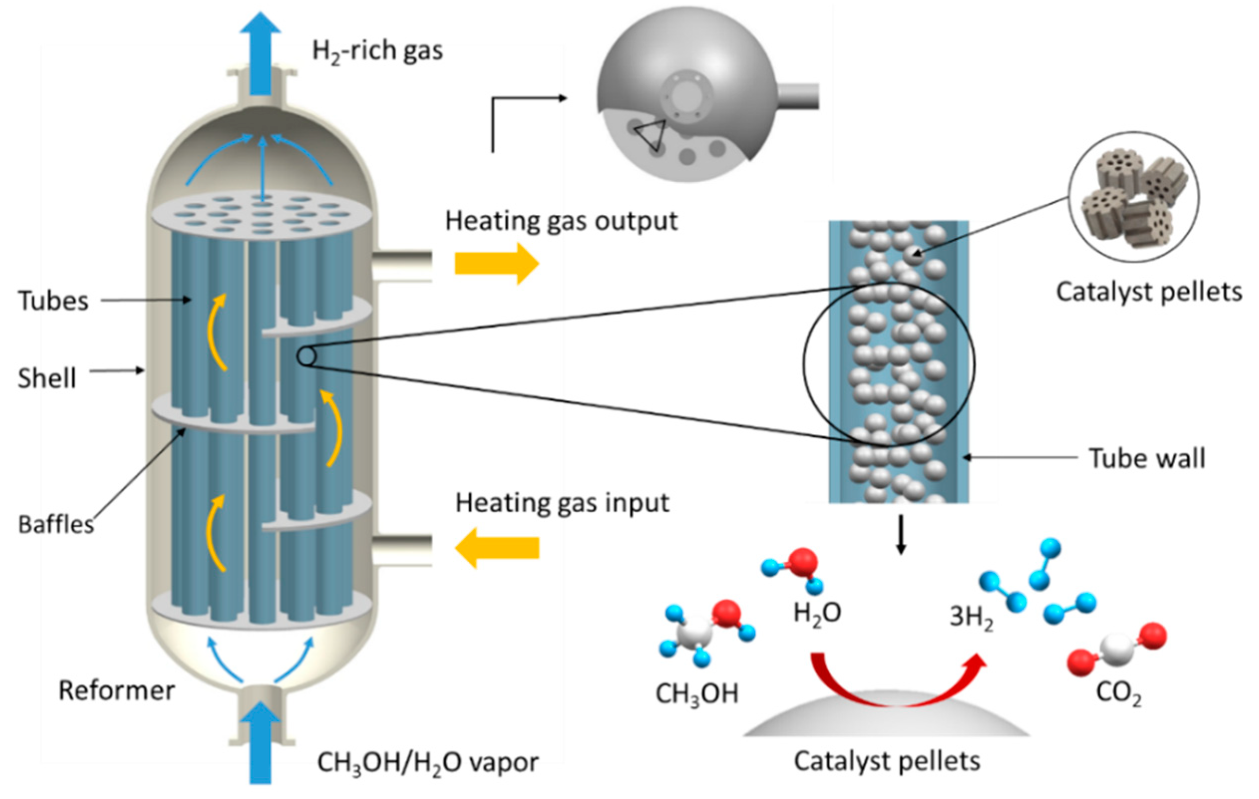
Generally, a reformed methanol fuel cell (RMFC) system is composed of a burner, an evaporator, several thermal fluid circuits, a methanol steam reformer and a fuel cell stack. Firstly, the mixture of methanol and water is pumped into the evaporator where the fuel is evaporated. The vapor fuel is then fed into the catalyst bed in the reformer and converted into hydrogen-rich gas by chemical reactions. The hydrogen-rich gas from the reformer is sent to the anode side of the fuel cell stack. The fuel cells utilize the hydrogen from anode side together with the oxygen from the cathode side to generate electricity by electrochemical reactions. The exhaust gas from the fuel cell stack is directed to the burner, where the residual hydrogen and methanol react with air in the burner. The generated heat is transferred into the catalyst bed by thermal fluid circuit. In this work, the methanol steam reformer as a subsystem of the RMFC system has been studied.
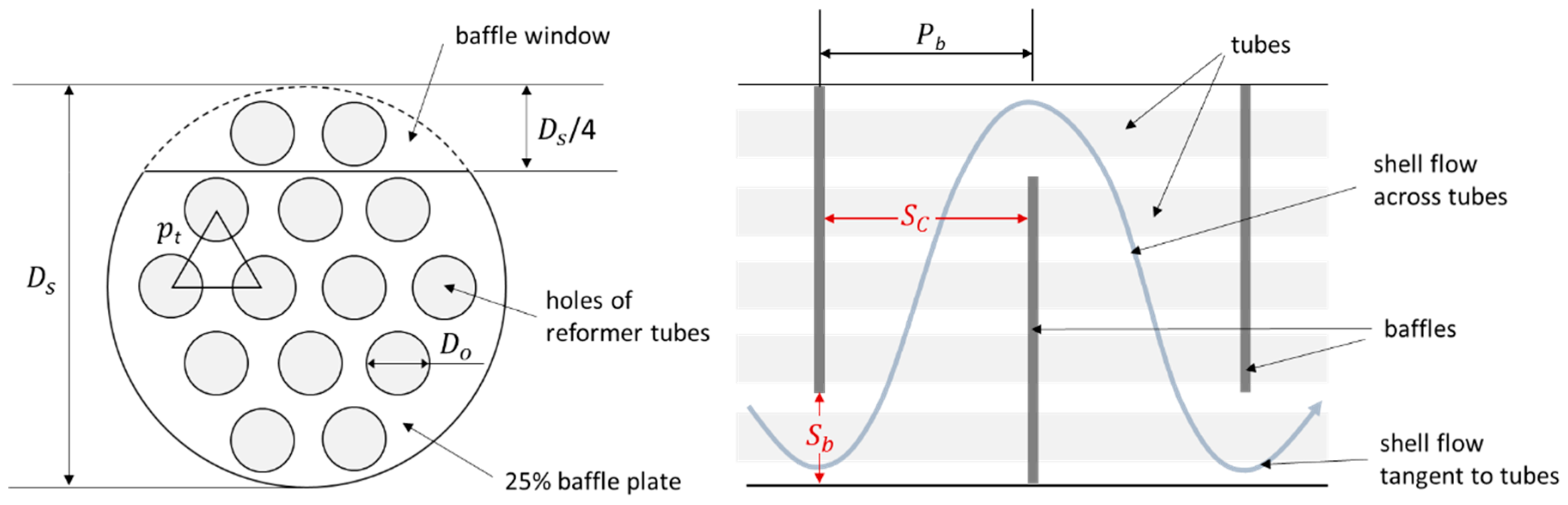
The reformer for MSR in this study is a multi-tubular packed-bed reformer. The structure of the heat-exchanger type reformer, including baffles, tubes and a shell, is presented in Figure 1. The reactor shell is usually surrounded by thermal insulation materials to avoid any significant amount of heat loss. Tubes packed with Cu/ZnO/Al2O3 catalyst are arranged in equilateral triangle tube bundles and installed inside the shell. The baffle plates are used to support the tube bundles, increase the flow distribution in the inter-tubular space and for an effective heat transfer between the tube side and shell side.
The heating gas from the burner flows through the shell side of the reformer, thereby providing an external heat source for the reactions. In the tube side, reactants flow through the catalyst bed, where the steam reforming reactions occur.

3. Model of the Methanol Steam Reformer

3.1. Kinetic Model of Reaction Rates

In this study, the process of methanol steam reforming consists of three reversible overall reactions: MSR, WGS and MD. For kinetic analysis of the reforming process over Cu/ZnO/Al2O3 catalyst, the Langmuir-Hinshelwood macro kinetic model based on the study of Peppley et al. [10] is used. This classic and comprehensive kinetic model is developed on the basis of several assumptions: hydrogen and oxygen-containing species adsorb on different active sites; the active sites for MD reaction are different from those for SRM and WGS reaction; the rate-determining step for both MSR and MD is the dehydrogenation of the adsorbed methoxy, while for WGS reaction the RDS is the formation of an intermediate formate species [12]. According to the Langmuir-Hinshelwood model, the rate expressions for three key reactions involved in the process can be expressed as follows:
r R = k R K C H 3 O ( 1 ) * ( p C H 3 O H / p H 2 1 2 ) ( 1 p H 2 3 p C O 2 / K R e q p C H 3 O H p H 2 O ) C S 1 T C S 1 a T ( 1 + K C H 3 O ( 1 ) * ( p C H 3 O H / p H 2 1 2 ) + K H C O O ( 1 ) * p C O 2 p H 2 1 2 + K O H ( 1 ) * ( p H 2 O / p H 2 1 2 ) ) ( 1 + K H ( 1 a ) 1 2 p H 2 1 2 ) ,
r W = k W K O H ( 1 ) * ( p C O p H 2 O / p H 2 1 2 ) ( 1 p H 2 p C O 2 / K W e q p C O p H 2 O ) C S 1 T 2 ( 1 + K C H 3 O ( 1 ) * ( p C H 3 O H / p H 2 1 2 ) + K H C O O ( 1 ) * p C O 2 p H 2 1 2 + K O H ( 1 ) * ( p H 2 O / p H 2 1 2 ) ) 2 ,
r D = k D K C H 3 O ( 2 ) * ( p C H 3 O H / p H 2 1 2 ) ( 1 p H 2 2 p C O / K D e q p C H 3 O H ) C S 2 T C S 2 a T ( 1 + K C H 3 O ( 2 ) * ( p C H 3 O H / p H 2 1 2 ) + K O H ( 2 ) * ( p H 2 O / p H 2 1 2 ) ) ( 1 + K H ( 2 a ) 1 2 p H 2 1 2 ) ,
where k j and K j e q are the rate constant and equilibrium constant of reaction j ( j = R , W ,   D ) respectively, K * is the adsorption coefficient, p i is the partial pressure of component i   ( i = CO 2 , CO , H 2 , CH 3 OH   and   H 2 O ) , C S 1 T , C S 1 a T , C S 2 T and C S 2 a T are the total site concentrations of site ‘1′, ‘1a’, ‘2′, and ‘2a’ respectively. The required parameters for the comprehensive kinetic model of methanol steam reforming can be found in [10]. The temperature dependence of each constants can be expressed using the Arrhenius expression [10,29,30]:
k R = k R e x p ( E R R T ) ,
k D = k D e x p ( E D R T ) ,
k w = k R e x p ( E W R T ) ,
K R e q = exp ( 50240 170.98 T 2.64 × 10 2 T 2 R T ) ,
K W e q = exp ( 41735 + 46.66 T 7.55 × 10 3 T 2 R T ) ,
K D e q = K R e q K W e q ,
K C H 3 O ( 1 ) * = e x p ( Δ S C H 3 O ( 1 ) * R Δ H C H 3 O ( 1 ) * R T ) ,
K H C O O ( 1 ) * = e x p ( Δ S H C O O ( 1 ) * R Δ H H C O O ( 1 ) * R T ) ,
K O H ( 1 ) * = e x p ( Δ S O H ( 1 ) * R Δ H O H ( 1 ) * R T ) ,
K H ( 1 a ) = e x p ( Δ S H ( 1 a ) R Δ H H ( 1 a ) R T ) ,
K C H 3 O ( 2 ) * = e x p ( Δ S C H 3 O ( 2 ) * R Δ H C H 3 O ( 2 ) * R T ) ,
K O H ( 2 ) * = e x p ( Δ S O H ( 2 ) * R Δ H O H ( 2 ) * R T ) ,
K H ( 2 a ) = e x p ( Δ S H ( 2 a ) R Δ H H ( 2 a ) R T ) ,
To calculate the rate r i   ( mol   s 1 ( kg   of   catalyst ) 1 ) of production i per time per mass of catalyst, it is necessary to combine the rate expressions r j   ( mol   s 1 m 2 ) for each individual reaction j and multiply by the surface area per unit mass of fresh catalyst S c   ( m 2 kg 1 ) :
r C O 2 = ( r R + r W ) S c ,
r C O = ( r D r W ) S c ,
r H 2 = ( 3 r R + 2 r D + r W ) S c ,
r C H 3 O H = ( r R + r D ) S c ,
r H 2 O = ( r R + r W ) S c ,

3.2. Pressure Drop in Catalyst Bed of the Packed-Bed Reformer

As a fluid passes through a packed bed, it experiences pressure loss. Especially when the size of tablets is small, the pressure drop in the catalyst bed has to be taken into consideration. In this paper, we assume that a set of porous cylindrical catalyst particles of uniform size are packed in cylindrical tubes. It is widely accepted that the pressure drop can be approximated by the semiempirical Ergun equation [31]:
d P d z = G ρ t D p ( 1 ϕ ϕ 3 ) [ 150 ( 1 ϕ ) η t D p + 1.75 G ] ,
Inside the packed bed, the viscosity of the gas mixture η t   ( Pa   s ) as well as the density of the gas mixture ρ t   ( kg   m 3 ) can be described as a function of reactor length z   ( m ) ; P   ( Pa ) is the pressure in the catalyst bed; ϕ is the void fraction of the catalyst bed; D p   ( m ) is the diameter of catalyst particles; G   ( kg   m 2 s 1 ) is the superficial mass velocity. The first-order solution for viscosity of pure gas η i   ( Pa   s ) can be expressed by using the Chun et al. method [32,33]:
η i = 40.785 F c ( M i T ) 1 2 V c 2 3 Ω v ,
F c = 1 0.2756 ω + 0.059035 μ r 4 + κ ,
κ = 0.682 + 4.704 [ ( n u m b e r   o f O H   g r o u p s ) / ( m o l e c u l a r   w e i g h t ) ] ,
μ r = 131.3 μ ( V c T c ) 1 2 ,
T * = 1.2593 T T c ,
Ω v = [ A ( T * ) B ] + C [ e x p ( D T * ) ] + E [ e x p ( F T * ) ] ,
where A = 1.16145 ,   B = 0.14874 ,   C = 0.52487 ,   D = 0.77320 ,   E = 2.16178   and   F = 2.43787 .
In this study, Herning and Zipperer’s method [34] was utilized to estimate the gas mixture viscosity η m   ( Pa   s ) in the methanol steam reformer:
η m = i = 1 5 x i η i j = 1 5 x j Φ i j ,
Φ i j = ( M j M i ) 1 2 = Φ j i 1 ,
The properties of each gas component are listed in Table 1.

3.3. Effectiveness Factor

The use of large catalyst size can reduce the pressure drop in the catalyst bed along the length, but may lead to a significant effect of intraparticle diffusion limitation on reaction rates. The reforming mixture in catalyst bed consists of five components: carbon dioxide (CO2), hydrogen (H2), water (H2O), methanol (CH3OH), carbon monoxide (CO). In catalyst bed, reactants transfer from the bulk fluid to the external surface of catalyst particle with reforming reactions taking place. Then the reactants will diffuse from the external surface with a higher concentration to reach the pores surface inside the catalyst through the pore tortuosity. The effective diffusivity is defined to describe the diffusion, which affects the chemical reactions inside catalyst particles. The effective diffusivity D i , eff   ( m 2   s 1 ) is estimated using the Maxwell-Stefan equation [35]:
1 D i , eff = j = 1 j i n x j D i j ( 1 x i N j x j N i ) + 1 D i , K ,
where D i j   ( m 2   s 1 ) is the diffusivity for a binary mixture of i and j . The Chapman-Enskog equation is used for the binary diffusivity at low density:
D i j = 0.0018583 T 3 / 2 ( 1 / M i + 1 / M j ) 1 / 2 P σ i j 2 Ω D ,
σ i j = σ i + σ j 2 ,
σ = 0.841 V c 1 / 3 ,
ε k = 0.75 T c ,
Ω D = ( 44.54 T i j * 4.909 + 1.911 T i j * 1.575 ) 0.10 ,
T i j * = k T ε i j ,
ε i j = ( ε i ε j ) 1 / 2 ,
where T   ( K ) is the operating temperature, P   ( atm ) is the pressure, M i   ( kg   mol 1 ) is the molar mass of component i , Ω D is the collision integral for diffusion. The Knudsen diffusivity D i , K   ( m 2   s 1 ) of component i is calculated by:
D i , K = d ¯ 3 8 R T π M i ,
where d ¯   ( m ) is the average pore diameter ( 6.4 × 10 9   m ) [36].
The effectiveness factor η (ranging from 0 to 1) is defined to describe the relative importance of diffusion and reaction limitations. For a first order reaction, the expression of the effectiveness factor is:
η ϕ 1 2 = 3 ( ϕ 1 coth ϕ 1 1 ) ,
where ϕ 1 is the Thiel modulus for a first-order reaction. The left-hand side is also called the Weisz-Prater parameter C W P , which is used to determine whether the diffusion is limiting the reactions. The shape of catalyst particles used in this study is cylindrical.
C W P =   η ϕ 1 2 ,
ϕ 1 2 = r j s ρ c r p 2 4 D i , eff C i s ,
where r j s   ( m o l   s 1 ( g   o f   c a t a l y s t ) 1 ) and C i s   ( m o l   m 3 ) are the rate of reaction j . and the concentration of component i . if the entire interior surface were exposed; r p   ( m ) is the radius of catalyst particle. If C W P 1 , the diffusion limitation and concentration gradient within the catalyst particle is supposed to be negligible. However, if C W P 1 , the internal diffusion limitation should be considered.

3.4. Mass and Energy Balance in Tube Side and Shell Side of the Packed-Bed Reformer

In this study, a comprehensive mathematical model is developed to evaluate the performance of the MSR process in the reformer. Tubes packed with catalyst particles were placed inside the reformer shell. Chemical reactions take place on the surface of Cu/ZnO/Al2O3 catalyst in the tube side of reformer. There is also a sweep of heating gas through the shell side, where no reaction happens. The model developed for the performance of the MSR process in the catalyst bed of one single tube can be extended to all tubes. The transport phenomena in the reactor-heat supply system can be described by the concentration of reactants and thermal profiles along the length of thereactor. In the radial direction of the methanol steam reformer, the convective heat transfer on both surfaces of the tube and the conductive heat transfer through the tube wall are considered. To simplify the mathematical model, major assumptions can be listed as follows:
  • steady-state conditions;
  • ideal gas behavior;
  • the radial mass and thermal dispersions in the tube side and shell side are negligible;
  • the methanol steam reaction is regarded as a first-order reaction;
  • the reformer-heat supply system is adiabatic from the surrounding.
In the catalyst bed, it is assumed that the reforming reactions are affected by internal diffusion of reactants. The effectiveness factor is set to be η for the catalyst. Therefore, the continuity equations for specie i is given by the following mole-balance equations:
d F i d z = η r i ρ c A c ,
where F i   ( mol · s 1 ) is the molar flow rate of component i , ρ c   ( kg · m 3 ) is the density of catalyst, A c ( m 2 ) is the area of cross section of the catalyst bed.
A steady state energy balance along the axis of catalyst bed leads to the following equation [31]:
d T t d z = U t a Δ T +   r j Δ H j S c ρ c   F i C p i A c ,
where C p i ( J   mol 1 K 1 ) is the specific heat of gas component i , which can be calculated from Table 2; Δ H j ( J   mol 1 ) is the enthalpy change of reaction j , which can be calculated from Table 3; Δ T   ( K ) is the temperature difference between shell side and tube side at length z   ( m ) ; a is the ratio of the heat transfer area inside the reactor to the reactor volume;   U t   ( Wm 2 K 1   or   Js 1 m 2 K 1 ) is the overall heat transfer coefficient of tube side.
A steady state energy balance along the axis of the shell side is written as:
d T s d z = N t U s A o Δ T F s C p s L ,
where U s   ( W   m 2 K 1   or   J   s 1 m 2 K 1 ) is the overall heat transfer coefficient outside the tube,   A o   ( m 2 ) is the heat transfer area outside the reactor tube, F s   ( mol Δ s 1 ) is the molar flow rate of heating air, C p s   ( J   kg 1 K 1 ) is the specific heat of heating air, L   ( m ) is the total length of the packed-bed reactor, and N t is the number of tubes in the reformer.
Figure 2 shows the cross section of a single tube and the radial temperature profile near the tube wall. There are three regions, where the temperature varies sharply, corresponding to three resistances to heat transfer: (1) the fluid film of the inner side of the tube, (2) the tube wall and (3) the fluid film outside the tube.
Therefore, the overall driving force can be decomposed into the sum of three separate temperature drops in each region:
Δ T = T s T t = ( T s T w o ) + ( T w o T w i ) + ( T w i T t ) ,
Film coefficients h t and h s are used to describe the convective heat-transfer rate between the fluid flow and tube wall in #1 and #3 fluid films separately. The film heat-transfer coefficient h t of the fluid film in tube side is defined as a proportionality constant between the heat flux d q / d A i and driving force ( T w i T t ) :
d q = h t d A i ( T w i T t ) ,
Similarly, the film heat-transfer coefficient of the fluid film in shell side h s is defined as:
d q = h s d A o ( T s T w o ) ,
The heat transfer occurs in the region #2 is pure conduction through the tube wall. This process can be described as:
d q = k w   x w d A l m ( T w o T w i ) ,
where x w   ( m ) is the thickness of tube wall; A i and A o are the internal and external surface areas of the tube wall separately; d A l m is the log-mean of d A i and d A o :
d A l m =   d A o d A i l n ( A o A i ) = π ( D o D i ) d L l n ( D o D i ) = π D l m d L ,
Assuming the steady-state heat transfer, the overall heat-transfer coefficient of the shell side U s and of the tube side U t can be described by [37]:
1 U s = 1 h t D o D i + x w k w   D o D l m + 1 h s ,
1 U t = 1 h t + x w k w   D i D l m + 1 h s D i D o ,
To calculate the overall heat-transfer coefficients, the heat transfer coefficient of the inner film h t can be estimated as:
h t = ( 0.4 R e 1 2 + 0.2 R e 2 3 ) P r 0.4 1 ϕ ϕ k m D p ,
where D p   ( m ) is the diameter of the catalyst particle, ϕ is the void fraction, P r is the Prandtl number, k m   ( W   m 1 K 1 ) is the average thermal conductivity of the gas mixture inside tubes.
For packed beds, the Reynolds number is defined by:
R e = D p G η m 1 1 ϕ ,
For a conventional packed-bed reformer in the form of shell-and-tube heat exchanger, the outer film coefficient h s is determined by the geometric parameters of reformer tubes and baffles inside the shell, which is shown in Figure 3. The bundle of tubes in a heat-and-tube heat exchanger reformer can be stacked in the triangular pitch which allows the tubes to be more tightly packed. The center-to-center distance between adjacent tubes is called the tube pitch, p t   ( m ) . For tubes packed in triangular pitch, the general requirement is that, p t 5 / 4   D i . A commonly used technique for increasing the heat transfer coefficient h s is to install baffle plates inside the shell, which partially block the cross-sectional area. The reduction of the cross-section area available for flow will increase the mass flux or velocity of the flow, also can prevent the formation of large stagnant regions, and thereby enhance h s . The baffle plate is a disc whose diameter is equal to the inner diameter of the reformer shell D s   ( m ) with holes for tubes to pass through. The part of the baffle plate called baffle window is formed by cutting off this part of plate to make a cross section available for the shell-side flow. Series of baffle plates are arranged inside shell along the length of the reformer with the baffle window alternately placed on top and bottom. The spacing between the baffle plates is baffle pitch, P b   ( m ) . Typical baffle pitch is a fraction of the shell diameter, 0.2 < P b / D s < 1 . In the design of reformer, many geometric parameters should be taken into account with respect to the optimum solution of arrangements of baffles and tubes.
A generally used equation for estimating the heat transfer coefficient in the shell-side film h s in a shell-tube heat exchanger is the Donohue equation:
h s = 0.2 ( D o G e η s ) 0.6 ( C p s η s k s ) 0.33 k s D o ,
where mass velocity G e   ( kg   m 2 s 1 ) is calculated by:
G e = G b G p ,
G b   ( kg   m 2 s 1 ) is the mass velocity through the baffle window:
G b = m s ˙ S b ,
where S b   ( m 2 ) is the area available for shell-side fluid flow through the baffle window:
S b = f b ( π D s 2 4 ) N b ( π D o 2 4 ) ,
G p   ( kg   m 2 s 1 ) is the mass velocity for crossflow perpendicular to the tubes:
G p = m s ˙ S p ,
where S p   ( m 2 ) is the interstitial area available for crossflow perpendicular to the bank of tubes at the widest point in the shell:
S p = P b D s ( 1 D o p t ) ,
where k s   ( W   m 1 K 1 ) is average thermal conductivity of shell-side gas, m ˙ s   ( kg   s 1 ) is the mass flow rate of shell-side gas, η s   ( Pa   s ) is the average viscosity of shell-side gas.

4. Results and Discussion

4.1. Comparison betweeen Counter-Current and Co-Current Reactor

In a methanol steam reformer, the packed bed reactor for endothermic reactions is always coupled with a combustor, which provides an external heating source by the flow of thermal air passing through the adjacent shell side. When the reactant and thermal air flow in opposite directions, the reactor is known as counter-current reactor. For co-current reactor, the flows are in the same direction. The thermal performance of both co-current and counter-current reactors was simulated with the inlet methanol-and-steam-mixture temperature of 433K and the inlet thermal air temperature of 673K. Results of methanol conversion are both above 95%. The CO concentration in the exit gas is 0.99% of the counter-current reactor and 0.34% of the co-current reactor. As Figure 4a represents, the methanol and steam mixture is fed from the entrance of the reactor in a low temperature, and the thermal air flows into the shell side from the opposite side of the reformer with a high temperature. The small temperature difference in the “cold side” leads to a diminished heat transfer so that a lower tube-side temperature. Therefore, the reaction rates of methanol reforming in the former part are limited. In the “hot side” of reactor, the temperature of catalyst bed increases rapidly. The increased operating temperature results to a high methanol conversion but also a higher CO concentration in the exit gas. In Figure 4b, the temperature profiles show that the tube-side temperature increases sharply after entering into the reactor. Due to the boosted endothermic reactions and reduced temperature difference, the temperature of tube side decreases gradually after the peak temperature around 500 K. The maximum temperature in co-current reactor is lower than counter-current reactor, which leads to a better performance in CO control and less catalyst deactivation. Moreover, the larger temperature difference drives a more efficient heat transfer, which benefits the higher reaction rate in the front part of the reactor. Therefore, co-current heat exchanger reformers are more favored.

4.2. Pressure Drop in Catalyst Bed

It is shown that the smaller-sized catalyst performs better than larger-sized catalyst and suffers from less deactivation, owing to the increase in the surface area and number of pore entrances caused by the decrease in the particle size [38]. However, in small-scale packed bed reformer, especially when smaller size of catalyst tablet is chosen, the effect of pressure drop becomes significant and has to be taken into consideration during the construction of the reactor. The effect of the particle size on the pressure along the catalyst bed is investigated by changing the particle diameter from 0.5 mm to 2.0 mm, which is shown in Figure 5. The particles packed in reformer tubes are nearly monodispersed in size and cylindrical in shape. As expected, the pressure decreases along the length of catalyst bed, and the decrease is favored at smaller particle sizes of catalyst. Additionally, the pressure drop is calculated based on Ergun equation without taking into account the increased porosity of the bed near the wall and the viscous friction at the wall. It is indicated that the value of actual pressure drop may reach 20% higher than the pressure drop calculated by Ergun equation when the tube-to-particle-diameter ratio D / d p is quite small [39]. In this study, the particle size of 1.5 mm is used. As recommended by BASF Catalyst Selectra®, when the particle size of catalyst is 1.5 mm, the pressure drop should be taken into consideration during the development of the reformer model.

4.3. Model Verification and the Effectiveness Factor

The reformer used for MSR in this paper is a multi-tubular fixed bed reactor. The external thermal air in the shell side is used for providing heat source for reforming reactions inside tubes. The overall heat transfer between shell side and tube side gas is similar to the case of shell-and-tube heat exchanger. The geometrical parameters and operating conditions of the reformer are shown in Table 4. The development of the reformer model is of high importance to predict the performance of the small-scale methanol steam reformer and consequently optimize the design. Essentially, the simulation model needs to be verified. Without taking into consideration of the effectiveness factor of reforming reactions, the simulation model built in MATLAB-Simulink platform was verified using data from a dynamic model of the methanol steam reformer in ASPEN. The comparison of methanol conversions calculated by Simulink model and ASPEN model is shown in Table 5, where a good agreement is be observed.
As the simulation results can be affected by internal diffusion of the catalyst particles, the effectiveness factor should be taking into consideration. In this paper, the cylinder catalyst particles with the size of 1.5 mm are used. To estimate the effectiveness factor by Equation (43), it is necessary to check the value of Weisz-Prater parameter C W P to learn if the diffusion limitation is significant within the catalyst particle. For both WGS and MD reactions, the value of C W P simulated under normal operating conditions is shown to be much smaller than 1. However, for the MSR reaction, C W P ranges from 0.5 to 6.45. Therefore, the intraparticle diffusion limitation of the WGS and MD reactions can be ignored and it of the MSR reaction should be considered in this model. The effectiveness factor profiles of MSR reaction are shown in Figure 6 as a function of the inlet flow rate of fuel and the position in the length of the catalyst bed.

4.4. Reformer Performance

The developed mathematical model in this study allows predicting the mole fractions of different species exiting the reformer under different conditions. The mole fractions of different species along the length of the reactor are presented in Figure 7, with the inlet fuel flow rate of methanol and water mixture at 4.5 L/h, the inlet temperature of thermal air at 673 K and the inlet temperature of vapor fuel at 433 K. The reforming process starts with only methanol and steam. As the reactions proceed along the length of the reactor, the mole fractions of methanol and steam reduction, while the mole fractions of reforming products including H2, CO and CO2 increase continuously.
In existing models of methanol steam reformer, the temperature of heating gas is usually considered constant along the reactor length, so that a separate energy balance of the shell side can be ignored to simplify the mathematical model. In order to simulate the operating performance of the reformer more accurately, the radial heat transfer and thermal behavior of the shell side have been considered in this work. As shown in Figure 8a, the effect of fuel flow rate on axial temperature profiles in both tube side and shell side was investigated. The flow rate of liquid water-and-methanol mixture varies from 3 to 6 L/h, with the mass flow rate of thermal air at 6 g/s, the inlet temperature of vapor fuel and thermal air at 433 K and 673 K, respectively. The temperature variation of catalyst bed inside tubes is related to the endothermic reaction of methanol steam reforming and the external heat from the shell side. With a lower flow rate of liquid fuel at 3 L/h, the tube-side temperature near the entrance of the reactor increases more rapidly compared to the higher flow rate cases. Because less methanol is participating in the reforming reactions, the energy absorbed by endothermic process is less than the energy transferred to the tube side depending on the temperature difference. It is widely accepted that the MSR process is favored at higher temperatures according to its thermodynamic characteristics. Therefore, the enhanced endothermic reactions due to a higher tube-side temperature results in a higher methanol conversion, which achieves nearly 100% at the exit of reactor as shown in Figure 8b. When operating with higher flow rates of vapor fuel at 5 and 6 L/h, the tube-side temperatures experience a momentary increase and then decrease along the length of reactor. With significant heat consumption by reactions inside tubes, the radial heat transfer gradually becomes hard to compensate for the heat loss because the drive force of temperature difference between the shell side and tube side tends to be smaller. In addition, with a lower operating temperature in the catalyst bed and a higher W / F CH 3 OH (ratio of catalyst weight to molar flow rate of methanol, kg   s / mol ), the methanol conversion with higher fuel flow rate is lower than other cases.
The effect of inlet temperature of the thermal air on the performance of reformer was investigated, and the axial temperature profiles in both tube side and shell side were illustrate in Figure 9a. The methanol conversion along the length of the reactor at different inlet temperature of the thermal air is represented in Figure 9b. The inlet temperature of the thermal air varies in the range of 573−723 K with the inlet temperature of vapor fuel at 433 K, the inlet flow rate of liquid fuel at 4.5 L/h, and the inlet flow rate of the thermal air at 6 g/s. As can be seen from the temperature profiles, the increasing temperature of the thermal air raises both the tube-side and the shell-side temperature along the reactor length. There is a sharp and momentary increase of tube-side temperature near the entrance of tube. In this part, the large driving force caused by temperature difference leads to a significant heat transfer from the shell side to the tube side. After the tube-side temperature has been increased, the increasing tendency slows down with the inlet temperature of thermal air at 723 K. It is known that higher operating temperature favors MSR process, and hence with a higher inlet temperature of thermal air, the reaction rate of MSR is enhanced, which leads to more absorption of energy owing to the endothermic process. However, the driving force of radial heat transfer due to the temperature difference increases simultaneously. The enhanced heat transfer provides sufficient heat and has an overwhelming effect on the temperature distribution compared with the effect of heat absorption. However, with the inlet temperature of thermal air lower than 673 K, the radial heat transfer is diminished due to the reduce driving force of radial heat transfer. The endothermic process still plays the critical role compared with the effect of heat transfer. Therefore, after a sharp increase at the entrance of the reactor, the temperature subsequently decreases with a lower inlet temperature of thermal air. Figure 9b represents the methanol conversion profile along the length of the reactor. With a higher inlet temperature of thermal air, the methanol conversion increases due to the enhanced reaction rate. The methanol conversion achieves nearly 100% at the exit of reactor with the inlet temperature of thermal air at 723 K.
For the application of HT-PEMFCs, the composition of produced H2-rich gas requires a high concentration of H2, and low concentrations of both methanol and CO. Araya et al. [40] has analyzed the effect of methanol and water vapor on the degradation of HT-PEMFC by polarization curves and impedance spectra. The work showed that the HT-PEMFC operated with 5% and 8% concentration of methanol in the anode gas had significant performance degradation. The results also showed that a 3% or lower methanol concentration in the anode gas feed showed a negligible impact on the performance of HT-PEMFC, which indicated that the HT-PEMFC had a tolerance of methanol concentration of up to about 3%. Therefore, 2% methanol concentration in the reformed gas could be a relatively low content to ensure the performance of the HT-PEMFC. With the acid-doped PBI electrolytes, the poisoning effect of CO has been studied by Li et al. [41,42], and found that the effect is very temperature-dependent and can be sufficiently suppressed at elevated temperature. The results showed that 3% CO can be tolerated when operating at 200 °C, and for 1% above 175 °C, and for 0.5% above 150 °C. Similar results have been achieved in [43] that when the HT-PEM fuel cell operated at 180 °C or above, the reformate gas with a higher CO concentration of 2−5% can be accepted. In addition, elevated concentration of CO has been reported to cause unexpected coke deposition over the catalyst of methanol steam reformer and covers the copper sites, which will have a negative effect on the reformer performance [36].
The developed mathematical model in this study allows analyzing the mole fraction profiles of residual methanol and CO as a byproduct in the reactant mixture when gave the operating parameters of the reformer. It is especially important to predict the concentration of different components in the exit gas which is fed into the fuel cell stack. The contours of methanol concentration in the exit gas of reformer are indicated in Figure 10a with different inlet temperatures of thermal air and different flow rates of liquid fuel. It can be seen that a higher temperature of thermal air leads to a lower mole fraction of methanol in the exit gas of the methanol steam reformer. Simultaneously, the increasing flow rate of fuel mixture causes an obvious increase of methanol concentration. As mentioned above, a higher methanol concentration due to lower inlet temperature of heating gas and a higher flow rate of fuel is unfavorable to the performance of HT-PEM fuel cell stack. In this paper, concentration lower than 2% is preferred to ensure a considerably low content of methanol.
The mole fraction profiles of CO in the exit gas of the reformer were illustrated in Figure 10b. As expected, with increasing inlet temperature of thermal air, the methanol decomposition reaction is promoted and the water-gas shift reaction is diminished, which leads to a sharply increasing trend of mole fraction of CO. In addition, increasing the flow rate of fuel mixture leads to a decrease of the CO mole fraction. Likewise, a higher CO concentration due to lower flow rate of fuel and higher temperature of heating gas should be controlled to a tolerable level. Generally, the CO concentration lower than 1% is acceptable. Therefore, to ensure that the reformate composition from the reformer is suitable for an HT-PEMFC, the operating parameters represented by the lines in the respective contours in Figure 10a,b are recommended.

4.5. Influence of Geometric Parameters in the Multi-Tubular Packed-Bed Reactor

It is widely accepted that the W / F C H 3 O H associate with the dominating convective heat transfer properties can strongly affect the performance of reformer. By keeping the overall weight of catalyst W   ( kg ) constant, which is substantially attained by setting the total volume of tubes invariant in the reformer, the impact of geometric parameters can be investigated. With the fixed overall catalyst load, the number of tubes will increase by a factor equal to the square of the factor by which the radius of tubes decreases. For the packed-bed reformer in the current work, the geometric parameters used to simulate the performance of the reformer are listed in Table 6 and Table 7.
Axial temperature profiles in catalyst bed with the variations of tube number and tube diameter in Table 6 are evaluated for the same mass of catalyst. The increase of tube diameter will lead to the reduction of tube number in the reformer correspondingly, which boosts the overall heat exchange area of reformer as well as the surface-to-volume ratio of a single cylindrical tube. As shown in Figure 11, tube-side temperatures have a sharp increase near the entrance of reformer owing to the driving force of temperature difference between the internal and external fluid. After the initial increase, the reformer with less tubes and larger tube diameter (case 4) results to a roughly constant tube-side temperature along the length of reactor. For the reformer with more tubes and smaller tube diameter (case 1), the tube-side temperature maintains the increasing trend until the maximum value, then progressively decreases along the length and reaches a final temperature at the exit of reformer even lower than the other cases. The temperature profiles in the catalyst bed are determined by the interplay between the rates of heat transfer and endothermic reaction. The decrease of tube diameter promotes the heat transfer, which favors the approach of catalyst bed to a higher temperature, hence increases the endothermic reaction rates. When the heat consumption of the endothermic reaction overcomes the heat supply from the external heating source, the temperature will progressively drop.
The variation of methanol conversion is directly related to the temperature profile in the catalyst bed. As shown in Figure 12a, the geometric parameters in case 1 lead to higher methanol conversion mainly because of its short pre-heat length and high operating temperature in catalyst bed. However, later the temperature drop limits the efficiency of MSR process and eventually results to an inconspicuously lower methanol conversion at the outlet of the reformer. Figure 12b shows the CO concentration profiles inside tubes along the length of the reactor. Accordingly, the geometric parameters of more tubes and smaller tube diameter contribute to a clear increase in CO concentration due to the higher operating temperature.
The number of tubes and welding operations of the reformer, due to the decrease in the tube diameter at fixed catalyst load, will increase the investment and industrial costs. In addition, the CO concentration of the outlet gas mixture is also higher in this case. Therefore, there is a tendency to investigate the possibility of adopting reactor tubes with a larger diameter [44]. However, the adoption of reformer with larger tube diameter may cause larger radial temperatures gradients and cold-spot inside the catalyst bed [22], which means that the heat supplied from external thermal air cannot effectively compensate the heat consumed by the reforming process, and this results in lower methanol conversion. Furthermore, for tubes with smaller diameter, especially for ratios D / d p smaller than 6, the impact of the porosity change near the tube walls cannot be neglected then [45]. Therefore, the choice of geometric parameters should be a trade-off between reformer performance and manufacturing costs.
One of the methods to improve the heat transfer properties of the reformer with fixed flow rate of thermal air is to increase the external heat transfer coefficient by installing baffle plates by increasing turbulence in shell-side fluid. The axial profiles of methanol conversion and CO concentration inside tubes are shown in Figure 13. With the constant length of tubes, the added number of baffle plates is associated with the reduction of baffle spacing. For the reformer with smaller baffle spacing and more baffle plates (case 4), a higher methanol conversion is attained with an increase in CO concentration at reformer outlet. This change can be explained by the increased operating temperature in catalyst bed due to the effective radial heat transfer of reformer. However, the larger number of baffles in the shell-side of reformer makes the fabrication more expensive.

5. Conclusions

Simulation based on a comprehensive pseudo-homogenous model of a conventional packed-bed reformer has been developed to investigate the effects of operating conditions and geometric parameters on temperature distribution, methanol conversion and CO concentration along the axis of the multi-tubular methanol steam reformer. The model took into account the main chemical reactions, and the mass and heat transfer phenomena in both tube side and shell side of the reformer. In the radial direction, the overall heat transfer coefficient including the convective heat transfer near the internal and external surfaces of the tube wall, and the conductive heat transfer through the tube wall has been considered. The Ergun equation was used to calculate the pressure drop inside catalyst bed. A dynamic model of the multi-tubular methanol steam reformer was developed in the platform of ASPEN. Good agreement of methanol conversion was achieved between the data of the MATLAB model and the ASPEN model. The performance of a counter-current reactor and a co-current reactor has been compared. Results showed that the reactor in the form of a co-current heat exchanger had a lower CO concentration and better heat transfer efficiency. The intraparticle diffusion limitation for MSR reaction was considered by taking into account the effectiveness factor along the reactor. Axial temperature profiles of both tube side and shell side with different flow rate of liquid fuel and different inlet temperature of thermal air were represented in this paper. The developed mathematical model also allowed analyzing the mole fractions along the length of reformer of residual methanol and generated CO in the gas mixture. The results revealed that lower flow rate of liquid fuel and higher inlet temperature of thermal air led to a better methanol conversion, but also a higher CO concentration in outlet gas mixture. Because the generate hydrogen through steam reforming is intended for use in HT-PEMFCs, the composition of the H2-rich gas requires a concentration of methanol lower than 2% and CO lower than 1%. Therefore, the operating conditions should be limited to a certain region, where a suitable composition of reformed gas for feeding into an HT-PEM fuel cell stack can be achieve. With fixed catalyst load, the increase in the number of tubes and decrease in the tube diameter improved the methanol conversion, while also increasing the CO concentration. In addition, the reformer with more baffle plates in the shell side achieved better methanol conversion at the cost of higher CO concentration. Therefore, the choice of geometric parameters should be a trade-off between the manufacturing costs and the reformer performance.

Author Contributions

Conceptualization, J.Z., S.S.A. and S.L.S.; data curation, J.Z.; formal analysis, J.Z. and S.S.A.; funding acquisition, S.K.K.; investigation, J.Z. and X.C.; methodology, J.Z., S.S.A. and S.L.S.; project administration, S.S.A. and S.K.K.; resources, S.K.K.; software, J.Z., S.L.S. and X.C.; supervision, S.S.A. and S.K.K.; validation, J.Z., S.S.A. and X.C.; visualization, J.Z.; writing, original draft, J.Z.; writing, review and editing, J.Z., S.S.A., X.C., S.L.S. and S.K.K. All authors have read and agreed to the published version of the manuscript.

Funding

The research leading to these results has received funding from the Chinese scholarship council (CSC) and from the Danish Energy Technology Development and Demonstration Program (EUDP) through the Commercial Breakthrough of Advanced fuel cells (COBRA Drive) project, grant number 64018-0118.

Conflicts of Interest

The authors declare no conflict of interest.

Nomenclature

a ratio of the heat transfer area inside the reactor to the reactor volume ( m 1 )
A c area of cross section of catalyst bed ( m 2 )
A i internal surface area of tube ( m 2 )
A o external surface area of tube ( m 2 )
C p i specific heat of gas component i ( Jmol 1 K 1 )
C S i T total surface concentration of site i   ( mol   m 2 )
C i s surface concentration of component i ( mol   m 3 )
C W P Weisz-Prater parameter
D p diameter of the catalyst particle in the reformer ( m )
D s diameter of the reformer shell ( m )
D i inner diameter of tube ( m )
D i j diffusivity for a binary mixture of i and j ( m 2 s 1 )
D i , K Knudsen diffusivity of component i ( m 2 s 1 )
D i , eff effective diffusivity ( m 2 s 1 )
D o outer diameter of tube ( m )
f b area fraction of baffle plate that is window (for 25% baffle plate, f b = 0.1955 )
E j activation energy for rate constant of reaction j   ( kJmol 1 )
F i molar flow rate of component i   ( mol   s 1 )
G superficial mass velocity ( m   s 1 )
G e mass velocity of shell-side fluid
G b mass velocity through the baffle window ( kg   m 2 s 1 )
G p mass velocity for crossflow perpendicular to the tubes ( kg   m 2 s 1 )
h individual heat transfer coefficient ( Wm 2 K 1   or   Js 1 m 2 K 1 )
k thermal conductivity ( Wm 1 K 1 )
k j rate constant of reaction j ( j = R ,   D   or   W ) ( m 2   s 1 mol 1 )
K i * adsorption coefficient of specie i ( bar 0.5 )
K j e q equilibrium constant of reaction j ( j = R ,   D   or   W )
L length of the packed-bed reactor ( m )
M molecular weight ( kg   mol 1 )
N t number of tubes
N b number of baffles
p i partial pressure of component i ( bar )
P pressure of the catalyst bed ( bar )
P b baffle spacing ( m )
P r Prandtl number
p t tube pitch ( m )
r i rate of formation of component i   ( mol   s 1 ( kg   of   catalyst ) 1 ) , the number of moles of i reacting per unit time per unit mass of catalyst
r j rate of reaction j ( j = R ,   D   or   W ) ( mol   s 1 m 2 ) , the number of moles of reaction per time per unit surface area
R gas constant ( Jmol 1 K 1 )
R e Reynolds number
S b area available for shell-side fluid flow through the baffle window ( m 2 )
S c surface area per unit mass of fresh catalyst ( m 2 kg 1 )
S p interstitial area available for crossflow perpendicular to the bank of tubes at the widest point in the shell ( m 2 )
U overall heat transfer coefficient ( Wm 2 K 1   or   Js 1 m 2 K 1 )
V c critical volume ( cm 3 mol 1 )
W weight of catalyst ( kg )
x i mole fraction of specie i
x w thickness of the tube wall ( m )
μ r dimensionless dipole moment ( D )
η i viscosity of fluid ( Pa   s )
η effectiveness factor
ρ density ( kg   m 3 )
ϕ void fraction
ϕ 1 Thiel modulus for a first-order reaction
ω acentric factor
κ special correction for highly polar substances
Δ H enthalpy change ( Jmol 1 )
Δ S i entropy change of adsorption for species i   ( Jmol 1 K 1 )
Δ T temperature difference ( K )
Subscripts
m gas mixture
c catalyst
t tube side of the reformer
s shell side of the reformer
w i inner side of tube wall
w o outer side of tube wall
w tube wall

References

  1. Edlund, D. Methanol Fuel Cell Systems: Advancing towards Commercialization; PAN: Stanford, CA, USA, 2016; ISBN 9814303143. [Google Scholar]
  2. Iulianelli, A.; Ribeirinha, P.; Mendes, A.; Basile, A. Methanol steam reforming for hydrogen generation via conventional and membrane reactors: A review. Renew. Sustain. Energy Rev. 2014, 29, 355–368. [Google Scholar] [CrossRef] [Green Version]
  3. Karim, A.; Bravo, J.; Gorm, D.; Conant, T.; Datye, A. Comparison of wall-coated and packed-bed reactors for steam reforming of methanol. Catal. Today 2005, 110, 86–91. [Google Scholar] [CrossRef]
  4. Dalena, F.; Senatore, A.; Basile, M.; Knani, S.; Basile, A.; Iulianelli, A. Advances in methanol production and utilization, with particular emphasis toward hydrogen generation via membrane reactor technology. Membranes 2018, 8, 98. [Google Scholar] [CrossRef] [PubMed] [Green Version]
  5. Sá, S.; Silva, H.; Brandão, L.; Sousa, J.M.; Mendes, A. Catalysts for methanol steam reforming-A review. Appl. Catal. B Environ. 2010, 99, 43–57. [Google Scholar] [CrossRef]
  6. Araya, S.S.; Zhou, F.; Liso, V.; Sahlin, S.L.; Vang, J.R.; Thomas, S.; Gao, X.; Jeppesen, C.; Kær, S.K. A comprehensive review of PBI-based high temperature PEM fuel cells. Int. J. Hydrogen Energy 2016, 41, 21310–21344. [Google Scholar] [CrossRef]
  7. Zhou, F.; Andreasen, S.J.; Kær, S.K.; Park, J.O. Experimental investigation of carbon monoxide poisoning effect on a PBI/H3PO4 high temperature polymer electrolyte membrane fuel cell: Influence of anode humidification and carbon dioxide. Int. J. Hydrogen Energy 2015, 40, 14932–14941. [Google Scholar] [CrossRef]
  8. Papavasiliou, J.; Avgouropoulos, G.; Ioannides, T. Steady-state isotopic transient kinetic analysis of steam reforming of methanol over Cu-based catalysts. Appl. Catal. B Environ. 2009, 88, 490–496. [Google Scholar] [CrossRef]
  9. Jiang, C.J.; Trimm, D.L.; Wainwright, M.S.; Cant, N.W. Kinetic study of steam reforming of methanol over copper-based catalysts. Appl. Catal. A Gen. 1993, 93, 245–255. [Google Scholar] [CrossRef]
  10. Peppley, B.A.; Amphlett, J.C.; Kearns, L.M.; Mann, R.F. Methanol-steam reforming on Cu/ZnO/Al2O3 catalysts. Part 2. A comprehensive kinetic model. Appl. Catal. A Gen. 1999, 179, 31–49. [Google Scholar] [CrossRef]
  11. Agrell, J.; Birgersson, H.; Boutonnet, M. Steam reforming of methanol over a Cu/ZnO/Al2O3 catalyst: A kinetic analysis and strategies for suppression of CO formation. J. Power Sources 2002, 106, 249–257. [Google Scholar] [CrossRef]
  12. Sá, S.; Sousa, J.M.; Mendes, A. Steam reforming of methanol over a CuO/ZnO/Al2O3 catalyst, part I: Kinetic modelling. Chem. Eng. Sci. 2011, 66, 4913–4921. [Google Scholar] [CrossRef]
  13. Herdem, M.S.; Mundhwa, M.; Farhad, S.; Hamdullahpur, F. Multiphysics Modeling and Heat Distribution Study in a Catalytic Microchannel Methanol Steam Reformer. Energy Fuels 2018, 32, 7220–7234. [Google Scholar] [CrossRef]
  14. Lee, M.T.; Greif, R.; Grigoropoulos, C.P.; Park, H.G.; Hsu, F.K. Transport in packed-bed and wall-coated steam-methanol reformers. J. Power Sources 2007, 166, 194–201. [Google Scholar] [CrossRef]
  15. Bravo, J.; Karim, A.; Conant, T.; Lopez, G.P.; Datye, A. Wall coating of a CuO/ZnO/Al2O3 methanol steam reforming catalyst for micro-channel reformers. Chem. Eng. J. 2004, 101, 113–121. [Google Scholar] [CrossRef]
  16. Cui, X.; Kær, S.K. Two-dimensional thermal analysis of radial heat transfer of monoliths in small-scale steam methane reforming. Int. J. Hydrogen Energy 2018, 43, 11952–11968. [Google Scholar] [CrossRef]
  17. Yoshida, K.; Tanaka, S.; Hiraki, H.; Esashi, M. A micro fuel reformer integrated with a combustor and a microchannel evaporator. J. Micromech. Microeng. 2006, 16, S191. [Google Scholar] [CrossRef]
  18. Chein, R.Y.; Chen, Y.C.; Lin, Y.S.; Chung, J.N. Experimental study on the hydrogen production of integrated methanol-steam reforming reactors for PEM fuel cells. Int. J. Therm. Sci. 2011, 50, 1253–1262. [Google Scholar] [CrossRef]
  19. Kim, T. Micro methanol reformer combined with a catalytic combustor for a PEM fuel cell. Int. J. Hydrogen Energy 2009, 34, 6790–6798. [Google Scholar] [CrossRef]
  20. Davieau, D.D.; Erickson, P.A. The effect of geometry on reactor performance in the steam-reformation process. Int. J. Hydrogen Energy 2007, 32, 1192–1200. [Google Scholar] [CrossRef]
  21. Vadlamudi, V.K.; Palanki, S. Modeling and analysis of miniaturized methanol reformer for fuel cell powered mobile applications. Int. J. Hydrogen Energy 2011, 36, 3364–3370. [Google Scholar] [CrossRef]
  22. Ma, H.; Zhou, M.; Ying, W.; Fang, D. Two-dimensional modeling of a plant-scale fixed-bed reactor for hydrogen production from methanol steam reforming. Int. J. Hydrogen Energy 2016, 41, 16932–16943. [Google Scholar] [CrossRef]
  23. Mears, D.E. Diagnostic criteria for heat transport limitations in fixed bed reactors. J. Catal. 1971, 20, 127–131. [Google Scholar] [CrossRef]
  24. Karim, A.; Bravo, J.; Datye, A. Nonisothermality in packed bed reactors for steam reforming of methanol. Appl. Catal. A Gen. 2005, 282, 101–109. [Google Scholar] [CrossRef]
  25. Vidal Vázquez, F.; Simell, P.; Pennanen, J.; Lehtonen, J. Reactor design and catalysts testing for hydrogen production by methanol steam reforming for fuel cells applications. Int. J. Hydrogen Energy 2016, 41, 924–935. [Google Scholar] [CrossRef]
  26. Montebelli, A.; Visconti, C.G.; Groppi, G.; Tronconi, E.; Ferreira, C.; Kohler, S. Enabling small-scale methanol synthesis reactors through the adoption of highly conductive structured catalysts. Catal. Today 2013, 215, 176–185. [Google Scholar] [CrossRef]
  27. Lee, J.K.; Ko, J.B.; Kim, D.H. Methanol steam reforming over Cu/ZnO/Al2O3 catalyst: Kinetics and effectiveness factor. Appl. Catal. A Gen. 2004, 278, 25–35. [Google Scholar] [CrossRef]
  28. Tesser, R.; Di Serio, M.; Santacesaria, E. Methanol steam reforming: A comparison of different kinetics in the simulation of a packed bed reactor. Chem. Eng. J. 2009, 154, 69–75. [Google Scholar] [CrossRef]
  29. Wan, Y.; Zhou, Z.; Cheng, Z. Hydrogen production from steam reforming of methanol over CuO/ZnO/Al2O3 catalysts: Catalytic performance and kinetic modeling. Chin. J. Chem. Eng. 2016, 24, 1186–1194. [Google Scholar] [CrossRef]
  30. Yaws, C.L. Chemical Properties Handbook; McGraw-Hill: New York, NY, USA, 1999; ISBN 0070734011. [Google Scholar]
  31. Scott Fogler, H. Elements of Chemical Reaction Engineering; Prentice-Hall International London: London, UK, 1987; Volume 42, ISBN 8120322347. [Google Scholar]
  32. Chung, T.H.; Ajlan, M.; Lee, L.L.; Starling, K.E. Generalized multiparameter correlation for nonpolar and polar fluid transport properties. Ind. Eng. Chem. Res. 2005, 27, 671–679. [Google Scholar] [CrossRef]
  33. Chung, T.H.; Lee, L.L.; Starting, K.E. Applications of Kinetic Gas Theories and Multiparameter Correlation for Prediction of Dilute Gas Viscosity and Thermal Conductivity. Ind. Eng. Chem. Fundam. 1984, 23, 8–13. [Google Scholar] [CrossRef]
  34. Poling, B.E.; Prausnitz, J.M.; O’connell, J.P. The Properties of Gases and Liquids; Mcgraw-Hill: New York, NY, USA, 2001; Volume 5. [Google Scholar]
  35. Taylor, R.; Krishna, R. Multicomponent Mass Transfer; John Wiley & Sons: Hoboken, NJ, USA, 1993; Volume 2, ISBN 0471574171. [Google Scholar]
  36. Agarwal, V.; Patel, S.; Pant, K.K. H2 production by steam reforming of methanol over Cu/ZnO/Al2O3catalysts: Transient deactivation kinetics modeling. Appl. Catal. A Gen. 2005, 279, 155–164. [Google Scholar] [CrossRef]
  37. McCabe, W.L.; Smith, J.C.; Harriott, P. Unit Operations of Chemical Engineering, 6th ed.; McGraw-Hill: New York, NY, USA, 2001; Volume 1130. [Google Scholar]
  38. Mochizuki, H.; Yokoi, T.; Imai, H.; Watanabe, R.; Namba, S.; Kondo, J.N.; Tatsumi, T. Facile control of crystallite size of ZSM-5 catalyst for cracking of hexane. Microporous Mesoporous Mater. 2011, 145, 165–171. [Google Scholar] [CrossRef]
  39. Winterberg, M.; Tsotsas, E. Impact of tube-to-particle-diameter ratio on pressure drop in packed beds. AIChE J. 2000, 46, 1084–1088. [Google Scholar] [CrossRef]
  40. Araya, S.S.; Grigoras, I.F.; Zhou, F.; Andreasen, S.J.; Kær, S.K. Performance and endurance of a high temperature PEM fuel cell operated on methanol reformate. Int. J. Hydrogen Energy 2014, 39, 18343–18350. [Google Scholar] [CrossRef] [Green Version]
  41. Li, Q.; He, R.; Gao, J.A.; Jensen, J.O.; Bjerrum, N.J. The CO poisoning effect in PEMFCs operational at temperatures up to 200 °C. J. Electrochem. Soc. 2003, 150, 1599–1605. [Google Scholar] [CrossRef] [Green Version]
  42. Li, Q.; Oluf, J.; Savinell, R.F.; Bjerrum, N.J. High temperature proton exchange membranes based on polybenzimidazoles for fuel cells. Prog. Polym. Sci. 2009, 34, 449–477. [Google Scholar] [CrossRef] [Green Version]
  43. Das, S.K.; Reis, A.; Berry, K.J. Experimental evaluation of CO poisoning on the performance of a high temperature proton exchange membrane fuel cell. J. Power Sources 2009, 193, 691–698. [Google Scholar] [CrossRef]
  44. Montebelli, A.; Visconti, C.G.; Groppi, G.; Tronconi, E.; Kohler, S. Optimization of compact multitubular fixed-bed reactors for the methanol synthesis loaded with highly conductive structured catalysts. Chem. Eng. J. 2014, 255, 257–265. [Google Scholar] [CrossRef]
  45. Arab, S.; Commenge, J.M.; Portha, J.F.; Falk, L. Methanol synthesis from CO2 and H2 in multi-tubular fixed-bed reactor and multi-tubular reactor filled with monoliths. Chem. Eng. Res. Des. 2014, 92, 2598–2608. [Google Scholar] [CrossRef]
Figure 1. Structure of the multi-tubular packed-bed reformer for methanol steam reforming.
Energies 13 00610 g001
Figure 2. Cross section of single tube and radial temperature profile.
Energies 13 00610 g002
Figure 3. Arrangement of tubes and baffles in the shell of reformer.
Energies 13 00610 g003
Figure 4. Temperature profiles of both tube side and shell side in a (a) counter-current reactor, and a (b) co-current reactor along the length of the reactor.
Energies 13 00610 g004
Figure 5. Pressure drop along the length of reactor with different particle sizes.
Energies 13 00610 g005
Figure 6. Effective factor of MSR reaction along the length of reactor with the inlet flow rate of fuel ranging from 3.5 to 5.0 L/h. The particle size of catalyst is 1.5 mm.
Energies 13 00610 g006
Figure 7. Profiles of mole fraction of each components along the length of reactor.
Energies 13 00610 g007
Figure 8. The effect of the mass flow rate of methanol-and-water mixture ranging from 3 to 6 L/h on (a) the temperature profile of both tube side and shell side, and (b) the methanol conversion along the length of reactor.
Energies 13 00610 g008
Figure 9. The effect of the inlet temperature of thermal air ranging from 573 to 723 K on (a) the temperature profile of both tube side and shell side, and (b) the methanol conversion along the length of reactor.
Energies 13 00610 g009
Figure 10. Profiles of (a) methanol concentration, and (b) CO concentration in the exit gas of reformer with different inlet flow rate of fuel mixture and inlet temperature of thermal air.
Energies 13 00610 g010
Figure 11. Temperature profiles of tube side along the length of reactor with different number and diameter of tubes.
Energies 13 00610 g011
Figure 12. Profiles of (a) methanol conversion, (b) CO concentration along the length of reactor with different number and diameter of tubes.
Energies 13 00610 g012
Figure 13. Profiles of (a) methanol conversion, (b) CO concentration along the length of reactor with different number and pitch of baffles.
Energies 13 00610 g013
Table 1. Basic constants values for the calculation of viscosity of gases.
Gas Components V c   ( c m 3   m o l 1 ) T c   ( K ) ω μ   ( D )
CH3OH118.00512.640.5651.70
H2O55.95647.140.3441.84
H264.2032.98−0.2170
CO93.10132.850.0450.122
CO294.07304.120.2250
Table 2. Specific heat of gases.
Species Specific   Heat   ( J / m o l · K )
H2 C P H 2 = a 1 + b 1 ( T 1000 ) + c 1 ( T 1000 ) 2 + d 1 ( T 1000 ) 3 + e 1 ( 1000 T ) 2 ,
H2O C P H 2 O   = a 2 + b 2 ( T 1000 ) + c 2 ( T 1000 ) 2 + d 2 ( T 1000 ) 3 + e 2 ( 1000 T ) 2 ,
CO2 C P CO 2 = a 3 + b 3 ( T 1000 ) + c 3 ( T 1000 ) 2 + d 3 ( T 1000 ) 3 + e 3 ( 1000 T ) 2 ,
CO C P CO   = a 4 + b 4 ( T 1000 ) + c 4 ( T 1000 ) 2 + d 4 ( T 1000 ) 3 + e 4 ( 1000 T ) 2 ,
CH3OH C P CH 3 OH   = 63.4 .
a 1 = 33.066178 a 2 = 30.92000 a 3 = 24.99735 a 4 = 25.56759
b 1 = 11.363417 b 2 = 6.832514 b 3 = 55.18696 b 4 = 6.096130
c 1 = 11.432816 c 2 = 6.7934356 c 3 = 33.69137 c 4 = 4.054656
d 1 = 2.772874 d 2 = 2.534480 d 3 = 7.948387 d 4 = 2.671301
e 1 = 0.158558 e 2 = 0.0821398 e 3 = 0.136638 e 4 = 0.131021
Table 3. Enthalpy change of reactions.
Δ H R = 4.95 × 10 4 + ( C P CO 2 + 3 C P H 2 C P CH 3 OH   C P H 2 O   ) ( T 298 )   J / mol
Δ H D = 9.07 × 10 4 + ( C P CO + 2 C P H 2 C P CH 3 OH   ) ( T 298 )   J / mol
Δ H W = 4.12 × 10 4 + ( C P CO 2 + C P H 2 C P H 2 O   C P CO ) ( T 298 )   J / mol
Table 4. Reactor specification and operating conditions of the reformer in this study.
ParametersValue
Catalyst particle diameter,   D p   ( mm ) 1.5
Catalyst density, ρ b   ( kg   m 3 ) 1300
Surface area of fresh catalyst, S c   ( m 2   kg 1   ) 102,000
Void fraction ϕ 0.38
Operating temperature of catalyst (K)503–563
Molar ratio of steam to methanol S / C 1.5
Pressure, P   ( bar ) 1
Tube dimension ( m ) 0.016 × 0.001
Number of tubes, N t 36
Inner diameter of reformer shell, D i   ( m ) 0.24
Reactor length, L   ( m ) 0.48
Table 5. Comparison of the methanol conversions calculated by Simulink model and Aspen model.
ParametersValue
Case 1Case 2Case 3Case 4Case 5Case 6Case 7Case 8Case 9
Mass flow rate of liquid fuel ( L / h ) 4.567.54.54.54.54.54.54.5
Mass flow rate of thermal air ( g / s ) 666426666
Inlet temperature of vapor fuel ( K ) 433433433433433453413433433
Inlet temperature of thermal air ( K ) 673673673673673673673623573
Result of Methanol Conversion
Simulink model ( % ) 95.3480.0366.7576.9245.7496.6393.8581.5262.71
ASPEN model ( % ) 95.1879.1065.7177.2146.3896.4293.7881.3162.81
Relative error ( % ) 0.171.161.56−0.38−1.400.220.070.26−0.16
Table 6. Geometric parameters of the packed-bed reformer with variation in the number and diameter of tubes.
ParametersValue
Case 1Case 2Case 3Case 4
Number of reactor tubes, N t 14436169
Inner diameter of the tubular reactor, D i   ( m ) 0.0080.0160.0240.032
Outer diameter of the tubular reactor, D o   ( m ) 0.0100.0180.0260.034
Tube pitch, p t   ( m ) 0.0150.0270.0390.051
Number of baffle plates, Nb4
Spacing between baffle plates, P b   ( m ) 0.12
Length of the reactor, L   ( m ) 0.48
Area fraction of baffle plate that is window, f b (for 25% baffle plate) 0.1955
Table 7. Geometric parameters of the packed-bed reformer with variation in the number and pitch of baffles.
ParametersValue
Case 1Case 2Case 3Case 4
Number of baffle plates, Nb3468
Spacing between baffle plates, P b   ( m ) 0.160.120.080.06
Number of reactor tubes, N t 16
Inner diameter of the tubular reactor, D i   ( m ) 0.024
Outer diameter of the tubular reactor, D o   ( m ) 0.026
Tube pitch, p t   ( m ) 0.039
Length of the reactor, L   ( m ) 0.48
Area fraction of baffle plate that is window, f b (for 25% baffle plate) 0.1955

