Experimental Investigations Conducted for the Characteristic Study of OM29 Phase Change Material and Its Incorporation in Photovoltaic Panel

 , , and
Abstract
:1. Introduction
2. Materials and Methods
2.1. Phase Change Material
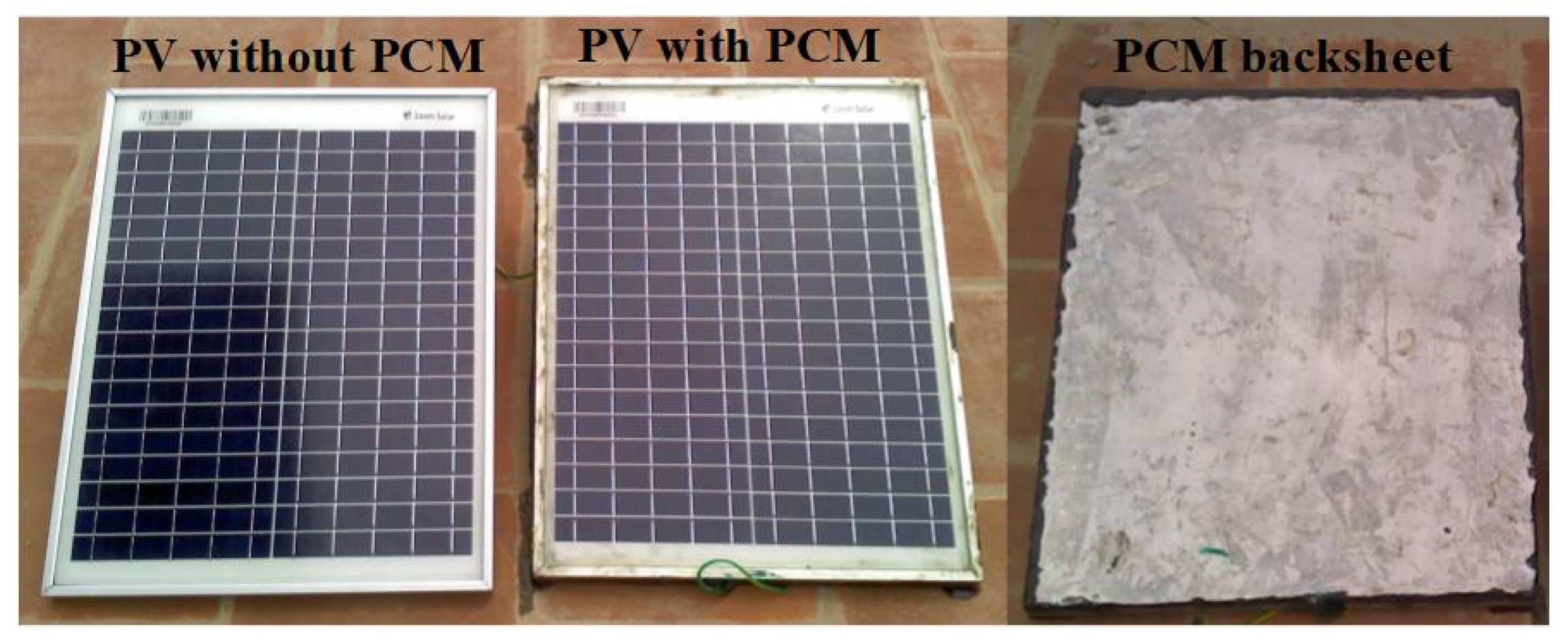
2.2. Experimental Setup
3. Thermal Heat Transfer Model
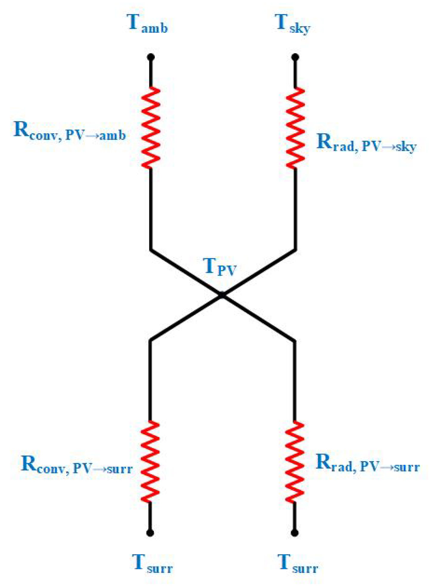
3.1. Heat Transfer Model for PV without PCM
Energy Balance for PV without PCM
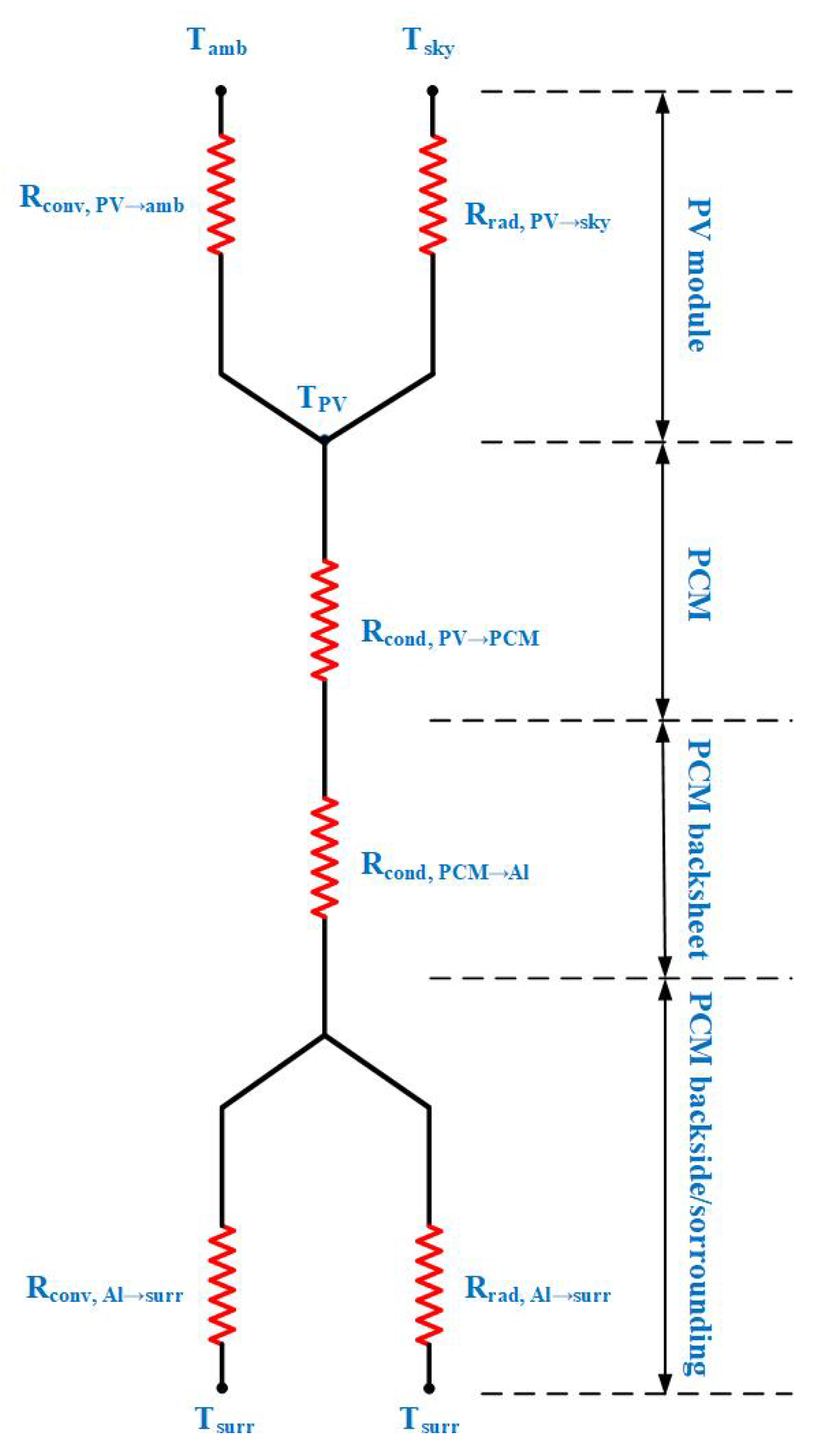
3.2. Heat Transfer Model for PV with PCM
Energy Balance for PCM Integrated PV Module
3.3. Energy Balance for Conduction Sourced PCM
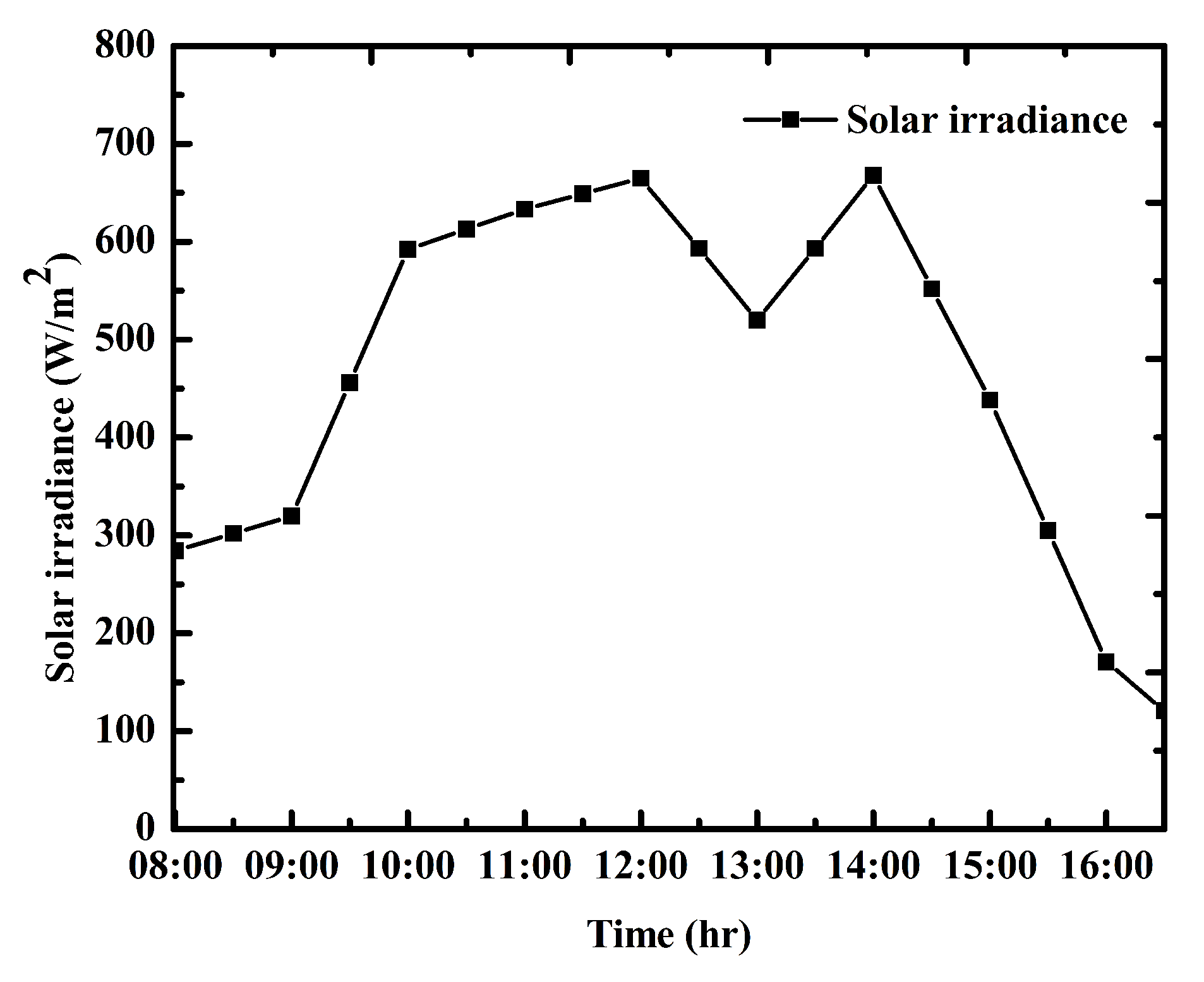
4. Results and Discussions
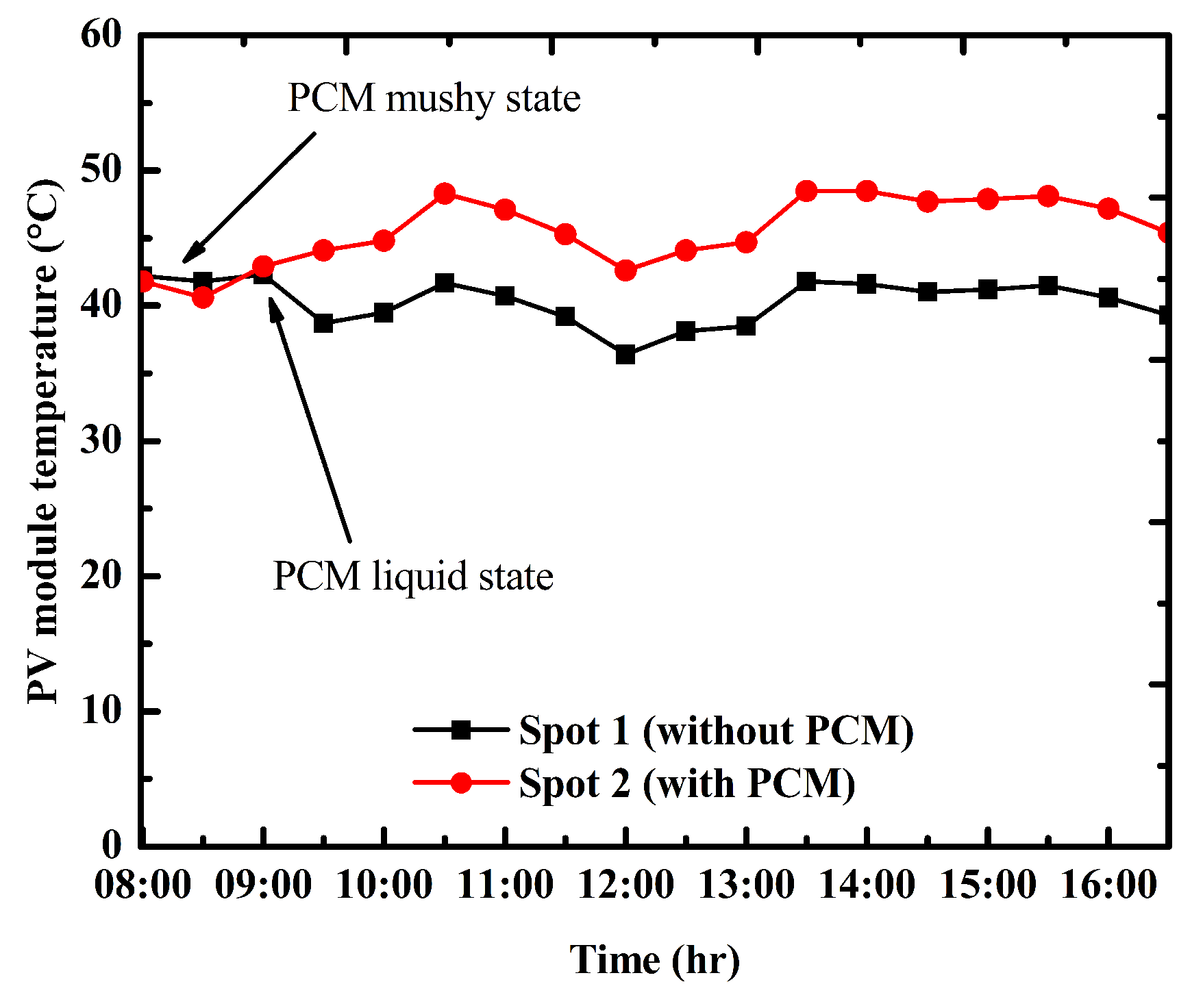
4.1. Temperature Profile of PV Module
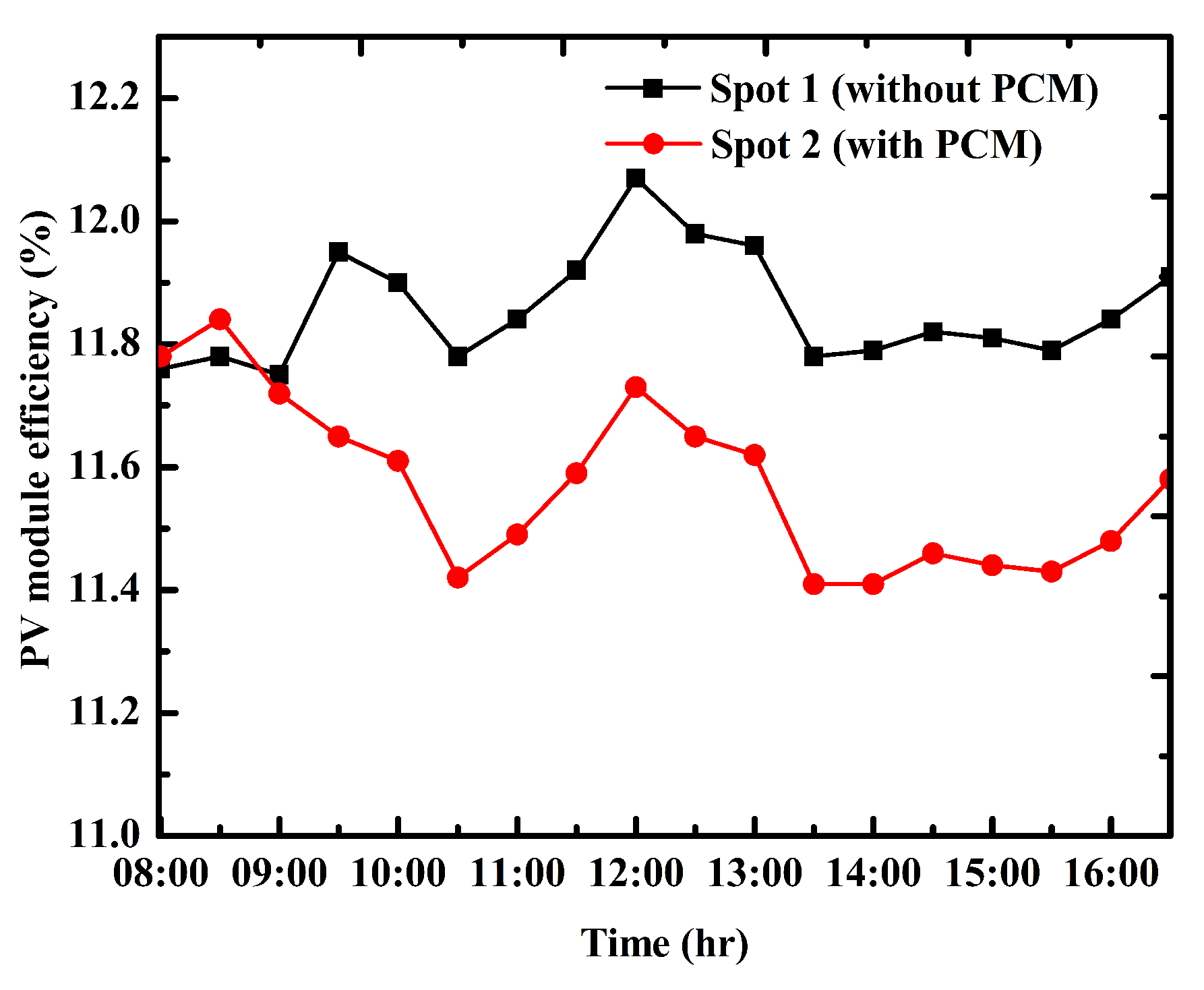
4.2. Temperature Corrected Electrical Efficiency
5. Conclusions
Author Contributions
Funding
Conflicts of Interest
References
- Zedalis, R.J. Global Energy & CO2 Status Report; Technical Report; Routledge: London, UK, 2017. [Google Scholar] [CrossRef]
- Qazi, A.; Hussain, F.; Rahim, N.A.; Hardaker, G.; Alghazzawi, D.; Shaban, K.; Haruna, K. Towards Sustainable Energy: A Systematic Review of Renewable Energy Sources, Technologies, and Public Opinions. IEEE Access 2019, 7, 63837–63851. [Google Scholar] [CrossRef]
- Elavarasan, R.M. Comprehensive Review on India’s Growth in Renewable Energy Technologies in Comparison With Other Prominent Renewable Energy Based Countries. J. Sol. Energy Eng. 2020, 142, 1–11. [Google Scholar] [CrossRef]
- Elavarasan, R.M.; Shafiullah, G.M.; Kumar, N.M.; Padmanaban, S. A State-of-the-Art Review on the Drive of Renewables in Gujarat, State of India: Present Situation, Barriers and Future Initiatives. Energies 2020, 13, 40. [Google Scholar] [CrossRef] [Green Version]
- Elavarasan, R.M. The Motivation for Renewable Energy and its Comparison with Other Energy Sources: A Review. Eur. J. Sustain. Dev. Res. 2019, 3, 1–19. [Google Scholar] [CrossRef]
- Das, N.K.; Islam, S.M. Conversion Efficiency Improvement in GaAs Solar Cells. In Large Scale Renewable Power Generation. Green Energy and Technology; Springer: Singapore, 2014; pp. 53–75. [Google Scholar] [CrossRef]
- Das, N.; Wongsodihardjo, H.; Islam, S. Modeling of multi-junction photovoltaic cell using MATLAB/Simulink to improve the conversion efficiency. Renew. Energy 2015, 74, 917–924. [Google Scholar] [CrossRef]
- Subramaniam, U.; Ganesan, S.; Bhaskar, M.S.; Padmanaban, S.; Blaabjerg, F.; Almakhles, D.J. Investigations of AC Microgrid Energy Management Systems Using Distributed Energy Resources and Plug-in Electric Vehicles. Energies 2019, 12, 2834. [Google Scholar] [CrossRef] [Green Version]
- Kumar, A.R.; Thangavelusamy, D.; Padmanaban, S.; Kothari, D.P. A Modified PWM Scheme to improve AC Power Quality for MLIs using PV Source. Int. J. Power Energy Syst. 2019, 39, 34–41. [Google Scholar] [CrossRef]
- Sridhar, V.; Umashankar, S.; Sanjeevikumar, P.; Ramachandaramurthy, V.K.; Mihet-Popa, L.; Fedák, V. Control Architecture for Cascaded H-Bridge Inverters in Large-Scale PV Systems. Energy Procedia 2018, 145, 549–557. [Google Scholar] [CrossRef]
- Elavarasan, M.; Mallick, G.; Saravanan, K. Investigations on Performance Enhancement Measures of the Bidirectional Converter in PV-Wind Interconnected Microgrid System. Energies 2019, 12, 2672. [Google Scholar] [CrossRef] [Green Version]
- Bhukya, M.N.; Kota, V.R.; Depuru, S.R. A Simple, Efficient, and Novel Standalone Photovoltaic Inverter Configuration With Reduced Harmonic Distortion. IEEE Access 2019, 7, 43831–43845. [Google Scholar] [CrossRef]
- Rajvikram, M.; Leoponraj, S. A method to attain power optimality and efficiency in solar panel. Beni-Suef Univ. J. Basic Appl. Sci. 2018, 7, 705–708. [Google Scholar] [CrossRef]
- Alami, A.H. Effects of evaporative cooling on efficiency of photovoltaic modules. Energy Convers. Manag. 2014, 77, 668–679. [Google Scholar] [CrossRef]
- Schiro, F.; Benato, A.; Stoppato, A.; Destro, N. Improving photovoltaics efficiency by water cooling: Modelling and experimental approach. Energy 2017, 137, 798–810. [Google Scholar] [CrossRef]
- Liang, R.; Wang, P.; Zhou, C.; Pan, Q.; Riaz, A.; Zhang, J. Thermal performance study of an active solar building façade with specific PV/T hybrid modules. Energy 2019, 116532. [Google Scholar] [CrossRef]
- Bahaidarah, H.; Subhan, A.; Gandhidasan, P.; Rehman, S. Performance evaluation of a PV (photovoltaic) module by back surface water cooling for hot climatic conditions. Energy 2013, 59, 445–453. [Google Scholar] [CrossRef]
- Sutanto, B.; Indartono, Y.S. Computational fluid dynamic (CFD) modelling of floating photovoltaic cooling system with loop thermosiphon. In Proceedings of the AIP Conference, Bali, Indonesia, 14–16 August 2019; Volume 2062, p. 020011(1-6). [Google Scholar] [CrossRef]
- Sellami, R.; Amirat, M.; Mahrane, A.; Slimani, M.E.A.; Arbane, A.; Chekrouni, R. Experimental and numerical study of a PV/Thermal collector equipped with a PV-assisted air circulation system: Configuration suitable for building integration. Energy Build. 2019, 190, 216–234. [Google Scholar] [CrossRef]
- Shahsavar, A.; Khanmohammadi, S.; Khaki, M.; Salmanzadeh, M. Performance assessment of an innovative exhaust air energy recovery system based on the PV/T-assisted thermal wheel. Energy 2018, 162, 682–696. [Google Scholar] [CrossRef]
- Krishnan, S.; Garimella, S.; Kang, S. A novel hybrid heat sink using phase change materials for transient thermal management of electronics. IEEE Trans. Components Packag. Technol. 2005, 28, 281–289. [Google Scholar] [CrossRef] [Green Version]
- Afshari-Bavil, M.; Dong, M.; Li, C.; Feng, S.; Zhu, L. Thermally Controllable High-Efficiency Unidirectional Coupling in a Double-Slit Structure Filled With Phase Change Material. IEEE Photonics J. 2019, 11, 1–8. [Google Scholar] [CrossRef]
- Karthikeyan, V.; Sirisamphanwong, C.; Sukchai, S. Thermal investigation of Paraffin Wax for Low-Temperature Application. J. Adv. Res. Dyn. Control. Syst. 2019, 11, 1437–1443. [Google Scholar]
- Stupar, A.; Drofenik, U.; Kolar, J.W. Optimization of Phase Change Material Heat Sinks for Low Duty Cycle High Peak Load Power Supplies. IEEE Trans. Components Packag. Manuf. Technol. 2012, 2, 102–115. [Google Scholar] [CrossRef]
- Alawadhi, E. Thermal Management of Blocks in a Channel Using Phase Change Material. IEEE Trans. Components Packag. Technol. 2009, 32, 89–99. [Google Scholar] [CrossRef]
- Fayaz, H.; Rahim, N.; Hasanuzzaman, M.; Nasrin, R.; Rivai, A. Numerical and experimental investigation of the effect of operating conditions on performance of PVT and PVT-PCM. Renew. Energy 2019, 143, 827–841. [Google Scholar] [CrossRef]
- Al-Waeli, A.H.; Chaichan, M.T.; Sopian, K.; Kazem, H.A.; Mahood, H.B.; Khadom, A.A. Modeling and experimental validation of a PVT system using nanofluid coolant and nano-PCM. Sol. Energy 2019, 177, 178–191. [Google Scholar] [CrossRef]
- Modjinou, M.; Ji, J.; Yuan, W.; Zhou, F.; Holliday, S.; Waqas, A.; Zhao, X. Performance comparison of encapsulated PCM PV/T, microchannel heat pipe PV/T and conventional PV/T systems. Energy 2019, 166, 1249–1266. [Google Scholar] [CrossRef]
- Nižetić, S.; Arıcı, M.; Bilgin, F.; Grubišić-Čabo, F. Investigation of pork fat as potential novel phase change material for passive cooling applications in photovoltaics. J. Clean. Prod. 2018, 170, 1006–1016. [Google Scholar] [CrossRef]
- Zhao, J.; Ma, T.; Li, Z.; Song, A. Year-round performance analysis of a photovoltaic panel coupled with phase change material. Appl. Energy 2019, 245, 51–64. [Google Scholar] [CrossRef]
- Al-Jethelah, M.S.M.; Al-Sammarraie, A.; Tasnim, S.H.; Mahmud, S.; Dutta, A. Effect of convection heat transfer on thermal energy storage unit. Open Phys. 2018, 16, 861–867. [Google Scholar] [CrossRef]
- Khanna, S.; Reddy, K.; Mallick, T.K. Performance analysis of tilted photovoltaic system integrated with phase change material under varying operating conditions. Energy 2017, 133, 887–899. [Google Scholar] [CrossRef]
- Huang, M.; Eames, P.; Norton, B. Thermal regulation of building-integrated photovoltaics using phase change materials. Int. J. Heat Mass Transf. 2004, 47, 2715–2733. [Google Scholar] [CrossRef]
- Nehari, T.; Benlakam, M.; Nehari, D. Effect of the Fins Length for the Passive Cooling of the Photovoltaic Panels. Period. Polytech. Mech. Eng. 2016, 60, 89–95. [Google Scholar] [CrossRef] [Green Version]
- Khanna, S.; Reddy, K.; Mallick, T.K. Optimization of finned solar photovoltaic phase change material (finned pv pcm) system. Int. J. Therm. Sci. 2018, 130, 313–322. [Google Scholar] [CrossRef]
- Biwole, P.; Eclache, P.; Kuznik, F. Improving the Performance of Solar Panels by the Use of Phase-Change Materials. In Proceedings of the World Renewable Energy Congress, Linköping, Sweden, 8–13 May 2011; Volume 57, pp. 2953–2960. [Google Scholar] [CrossRef] [Green Version]
- Rajvikram, M.; Sivasankar, G. Experimental study conducted for the identification of best heat absorption and dissipation methodology in solar photovoltaic panel. Sol. Energy 2019, 193, 283–292. [Google Scholar] [CrossRef]
- Wongwuttanasatian, T.; Sarikarin, T.; Suksri, A. Performance enhancement of a photovoltaic module by passive cooling using phase change material in a finned container heat sink. Sol. Energy 2020, 195, 47–53. [Google Scholar] [CrossRef]
- Rajvikram, M.; Leoponraj, S.; Ramkumar, S.; Akshaya, H.R.; Dheeraj, A. Experimental investigation on the abasement of operating temperature in solar photovoltaic panel using PCM and aluminium. Sol. Energy 2019, 188, 327–338. [Google Scholar] [CrossRef]
- Nada, S.; El-Nagar, D.; Hussein, H. Improving the thermal regulation and efficiency enhancement of PCM-Integrated PV modules using nano particles. Energy Convers. Manag. 2018, 166, 735–743. [Google Scholar] [CrossRef]
- Stropnik, R.; Stritih, U. Increasing the efficiency of PV panel with the use of PCM. Renew. Energy 2016, 97, 671–679. [Google Scholar] [CrossRef]
- Mahamudul, H.; Silakhori, M.; Henk Metselaar, I.; Ahmad, S.; Mekhilef, S. Development of a temperature regulated photovoltaic module using phase change material for Malaysian weather condition. Optoelectron. Adv. Mater. Rapid Commun. 2014, 8, 1243–1245. [Google Scholar]
- Polymers, P. Technical Data Sheet of savE® OM29; PLUSS: Haryana, India, 2017. [Google Scholar]
- Waqas, A.; Ji, J. Thermal management of conventional PV panel using PCM with movable shutters—A numerical study. Sol. Energy 2017, 158, 797–807. [Google Scholar] [CrossRef]
- Hasan, A.; Sarwar, J.; Alnoman, H.; Abdelbaqi, S. Yearly energy performance of a photovoltaic-phase change material (PV-PCM) system in hot climate. Sol. Energy 2017, 146, 417–429. [Google Scholar] [CrossRef]
- Li, Z.; Ma, T.; Zhao, J.; Song, A.; Cheng, Y. Experimental study and performance analysis on solar photovoltaic panel integrated with phase change material. Energy 2019, 178, 471–486. [Google Scholar] [CrossRef]
- Siahkamari, L.; Rahimi, M.; Azimi, N.; Banibayat, M. Experimental investigation on using a novel phase change material (PCM) in micro structure photovoltaic cooling system. Int. Commun. Heat Mass Transf. 2019, 100, 60–66. [Google Scholar] [CrossRef]
- Abdollahi, N.; Rahimi, M. Potential of water natural circulation coupled with nano-enhanced PCM for PV module cooling. Renew. Energy 2020, 147, 302–309. [Google Scholar] [CrossRef]
- Preet, S.; Bhushan, B.; Mahajan, T. Experimental investigation of water based photovoltaic/thermal (PV/T) system with and without phase change material (PCM). Sol. Energy 2017, 155, 1104–1120. [Google Scholar] [CrossRef]
- Li, D.; Xuan, Y.; Yin, E.; Li, Q. Conversion efficiency gain for concentrated triple-junction solar cell system through thermal management. Renew. Energy 2018, 126, 960–968. [Google Scholar] [CrossRef]
- Klemm, T.; Hassabou, A.; Abdallah, A.; Andersen, O. Thermal energy storage with phase change materials to increase the efficiency of solar photovoltaic modules. Energy Procedia 2017, 135, 193–202. [Google Scholar] [CrossRef]
- Gaur, A.; Ménézo, C.; Giroux-Julien, S. Numerical studies on thermal and electrical performance of a fully wetted absorber PVT collector with PCM as a storage medium. Renew. Energy 2017, 109, 168–187. [Google Scholar] [CrossRef]
- Sardarabadi, M.; Passandideh-Fard, M.; Maghrebi, M.J.; Ghazikhani, M. Experimental study of using both ZnO/water nanofluid and phase change material (PCM) in photovoltaic thermal systems. Sol. Energy Mater. Sol. Cells 2017, 161, 62–69. [Google Scholar] [CrossRef]
- Soares, N.; Costa, J.; Gaspar, A.; Matias, T.; Simões, P.; Durães, L. Can movable PCM-filled TES units be used to improve the performance of PV panels? Overview and experimental case-study. Energy Build. 2020, 210, 109743. [Google Scholar] [CrossRef]
- Reiter, C.N.; Trinkl, C.; Zörner, W.; Hanby, V.I. A Dynamic Multinode Model for Component-Oriented Thermal Analysis of Flat-Plate Solar Collectors. J. Sol. Energy 2015, 2015, 1–16. [Google Scholar] [CrossRef] [Green Version]
- Chaabane, M.; Mhiri, H.; Bournot, P. Thermal performance of an integrated collector storage solar water heater (ICSSWH) with phase change materials (PCM). Energy Convers. Manag. 2014, 78, 897–903. [Google Scholar] [CrossRef]
- Skoplaki, E.; Palyvos, J. On the temperature dependence of photovoltaic module electrical performance: A review of efficiency/power correlations. Sol. Energy 2009, 83, 614–624. [Google Scholar] [CrossRef]
- Hendricks, J.H.C.; Sark, W.G.J.H.M. Annual performance enhancement of building integrated photovoltaic modules by applying phase change materials. Prog. Photovoltaics Res. Appl. 2011, 20. [Google Scholar] [CrossRef] [Green Version]
- Klugmann-Radziemska, E.; Wcisło-Kucharek, P. Photovoltaic module temperature stabilization with the use of phase change materials. Sol. Energy 2017, 150, 538–545. [Google Scholar] [CrossRef]
- Waqas, A.; Jie, J. Effectiveness of Phase Change Material for Cooling of Photovoltaic Panel for Hot Climate. J. Sol. Energy Eng. 2018, 140, 1–19. [Google Scholar] [CrossRef]
- Khanna, S.; Reddy, K.; Mallick, T.K. Optimization of solar photovoltaic system integrated with phase change material. Sol. Energy 2018, 163, 591–599. [Google Scholar] [CrossRef]
- Abdulmunem, A.R. Passive Cooling By Utilizing the Combined PCM /Aluminum Foam Matrix To Improve Solar Panels Performance: Indoor Investigation. Iraqi J. Mech. Mater. Eng. 2017, 17, 712–723. [Google Scholar]
- Maiti, S.; Banerjee, S.; Vyas, K.; Patel, P.; Ghosh, P.K. Self regulation of photovoltaic module temperature in V-trough using a metal-wax composite phase change matrix. Sol. Energy 2011, 85, 1805–1816. [Google Scholar] [CrossRef]
- Hachem, F.; Abdulhay, B.; Ramadan, M.; El Hage, H.; El Rab, M.G.; Khaled, M. Improving the performance of photovoltaic cells using pure and combined phase change materials—Experiments and transient energy balance. Renew. Energy 2017, 107, 567–575. [Google Scholar] [CrossRef]
- Karthikeyan, V.; Prasannaa, P.; Sathishkumar, N.; Emsaeng, K.; Sukchai, S.; Sirisamphanwong, C. Selection and preparation of suitable composite phase change material for PV module cooling. Int. J. Emerg. Technol. 2019, 10, 385–394. [Google Scholar]


| Author | PCM/Location | System Description | TPV without PCM (°C) | TPV with PCM (°C) |
|---|---|---|---|---|
| Waqas et al., [44] | RT44/PV | PCMs are filled in a movable container to detach from the PV module back surface when it turns to be liquid. Yearly experimental results reveal that in summer there occurred a higher TPV reduction. | 64 | 42 |
| Hasan et al., [45] | RT42/PV | Yearly performance of RT42 integrated PV module enhances the electrical efficiency by about 5.9% and higher TPV reduction was achieved during April. | 71 | 61 |
| Zhenpeng et al., [46] | Paraffin 35/ China | One month experimental analysis shows that, on 19 July, the highest electrical energy conversion noticed in the range of 499– 524 Wh. | 68.7 | 53 |
| Leila et al., [47] | Sheep fat/ indoor | Sheep fat as PCM performed better than paraffin wax and cooled water flows in the channel to enhance the heat transfer. | 87 | 61.5 |
| Nasrin et al., [48] | Composed oil/ indoor | Zigzag PCM container along with the combination of composed oil (coconut oil+sunflower oil) with boehmite. The final result aids in better TPV reduction for composed oil with boehmite. | 72 | 42.5 |
| Sajan et al., [49] | RT30/ India | Hybrid application of water-based PCM integration enhances the efficiency more than water-based cooling technique. | 78 | 57 |
| Nada et al., [40] | RT55/ Egypt | Al2O3 nanoparticle improves the PCM thermal absorption capability with an increase in thermal conductivity. | 75 | 49.3 |
| Dianhong et al., [50] | Paraffin 50/China | The thermoelectric generator attached heatsink incorporated behind the PCM container to utilize the stored thermal energy of PCM. | 65 | 51 |
| Torsten et al., [51] | RT54HC/ Qatar | Metal fiber porous foam is impregnated with PCM to enhance the higher heat transfer from the PV module to PCM. | 80 | 60 |
| Ankita et al., [52] | OM39/ France | A fully wetted absorber channel removes the thermal energy from the PV module and it transfers to the PCM container. | 69.17 | 53.86 |
| Sardarabadu et al., [53] | Paraffin 42/Iran | Deionized water and ZnO nanofluid used as working fluid to carry out the PCM temperature for PVT application. | 62 | 45 |
| Modjinou et al., [28] | PCM 45/ China | A microchannel heat pipe is used to circulate the working fluid for both PVT and PVT- PCM. | 75 | 60 |
| Soares et al., [54] | RT22/ Portugal | Five days of experimental results reveal that movable thermal energy storage system claims negative impact on peak sunshine hours because selected RT22 PCM is not capable of this desired location. | 58 | 72 |
| Sl. | Property | Range |
|---|---|---|
| 1 | Melting temperature (°C) | 29 |
| 2 | Freezing temperature (°C) | 26 |
| 3 | Latent heat of fusion (kJ/kg) | 194 |
| 4 | Liquid density (Kg/m3) | 870 |
| 5 | Solid density (Kg/m3) | 976 |
| 6 | Liquid specific heat capacity (kJ/kgK) | 2.71 |
| 7 | Solid specific heat capacity (kJ/kgK) | 2.32 |
| 8 | Liquid thermal conductivity (W/mK) | 0.172 |
| 9 | Solid thermal conductivity (W/mK) | 0.293 |
| 10 | Congruent melting | YES |
| 11 | Thermal stability (No.) | ∼2000 |
| 12 | Maximum operating temperature | 120 |
| Time (h) | PV without PCM (°C) | PV with PCM (°C) | ||
|---|---|---|---|---|
| Front Surface | Back Surface | PV Front Surface | PCM Backsheet | |
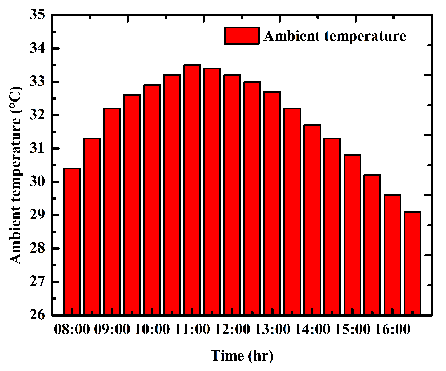
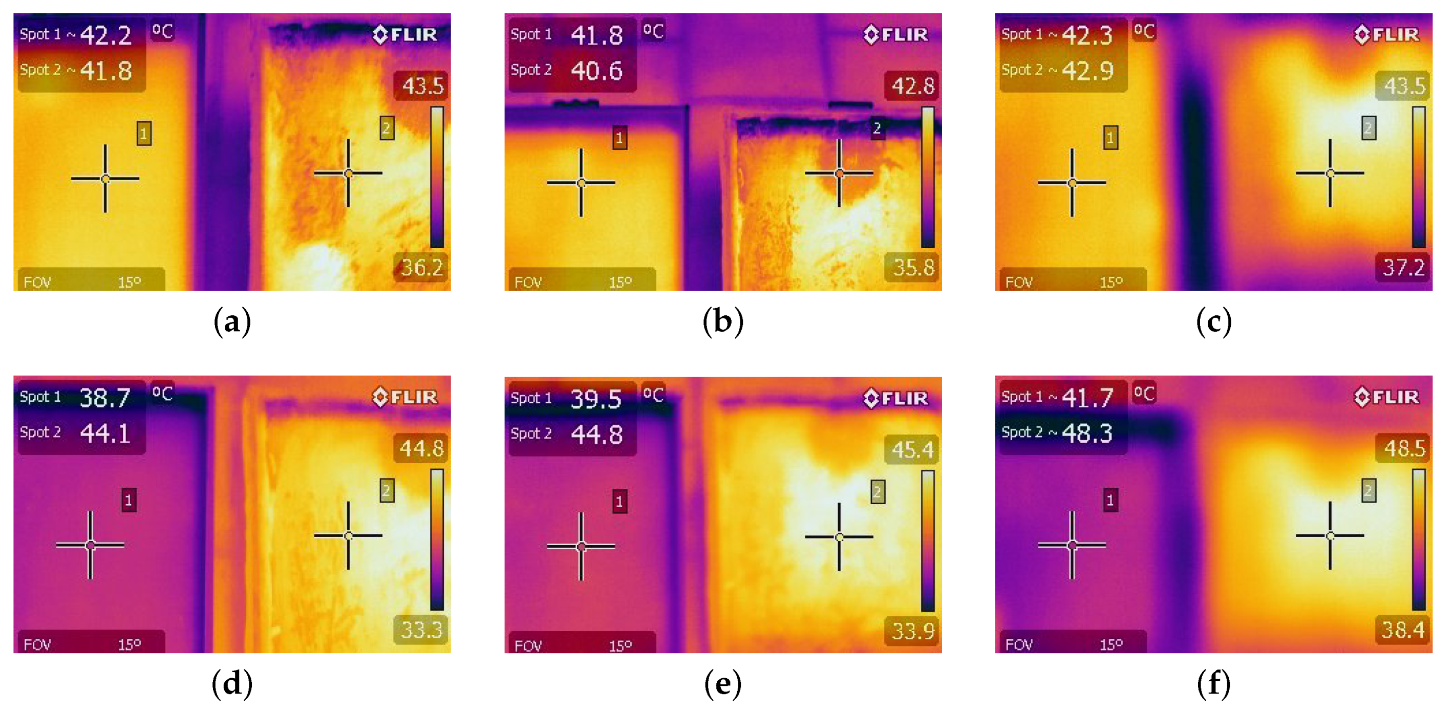
| 8:00 | 42.2 | 44.3 | 41.8 | 27.3 |
| 8:30 | 41.8 | 43.8 | 40.6 | 28.1 |
| 9:00 | 42.3 | 44.6 | 42.9 | 28.9 |
| 9:30 | 38.7 | 43.6 | 44.1 | 32.5 |
| 10:00 | 39.5 | 44.1 | 44.8 | 33.8 |
| 10:30 | 41.7 | 46.8 | 48.3 | 37.5 |
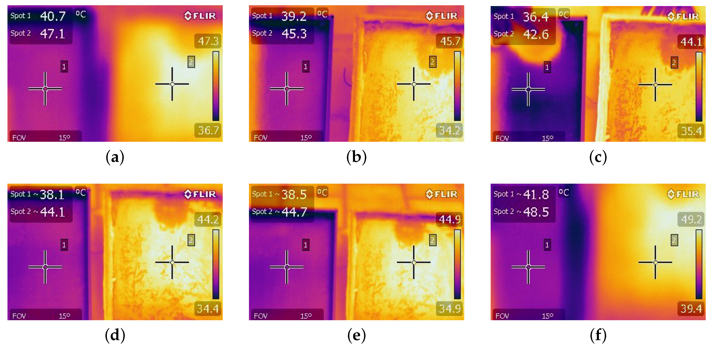
| 11:00 | 40.7 | 46.1 | 47.1 | 38.6 |
| 11:30 | 39.2 | 45.8 | 45.3 | 39.1 |
| 12:00 | 36.4 | 42.8 | 42.6 | 38.4 |
| 12:30 | 38.1 | 44.5 | 44.1 | 38.7 |
| 13:00 | 38.5 | 45.3 | 44.7 | 39.1 |
| 13:30 | 41.8 | 47.1 | 48.5 | 41.9 |
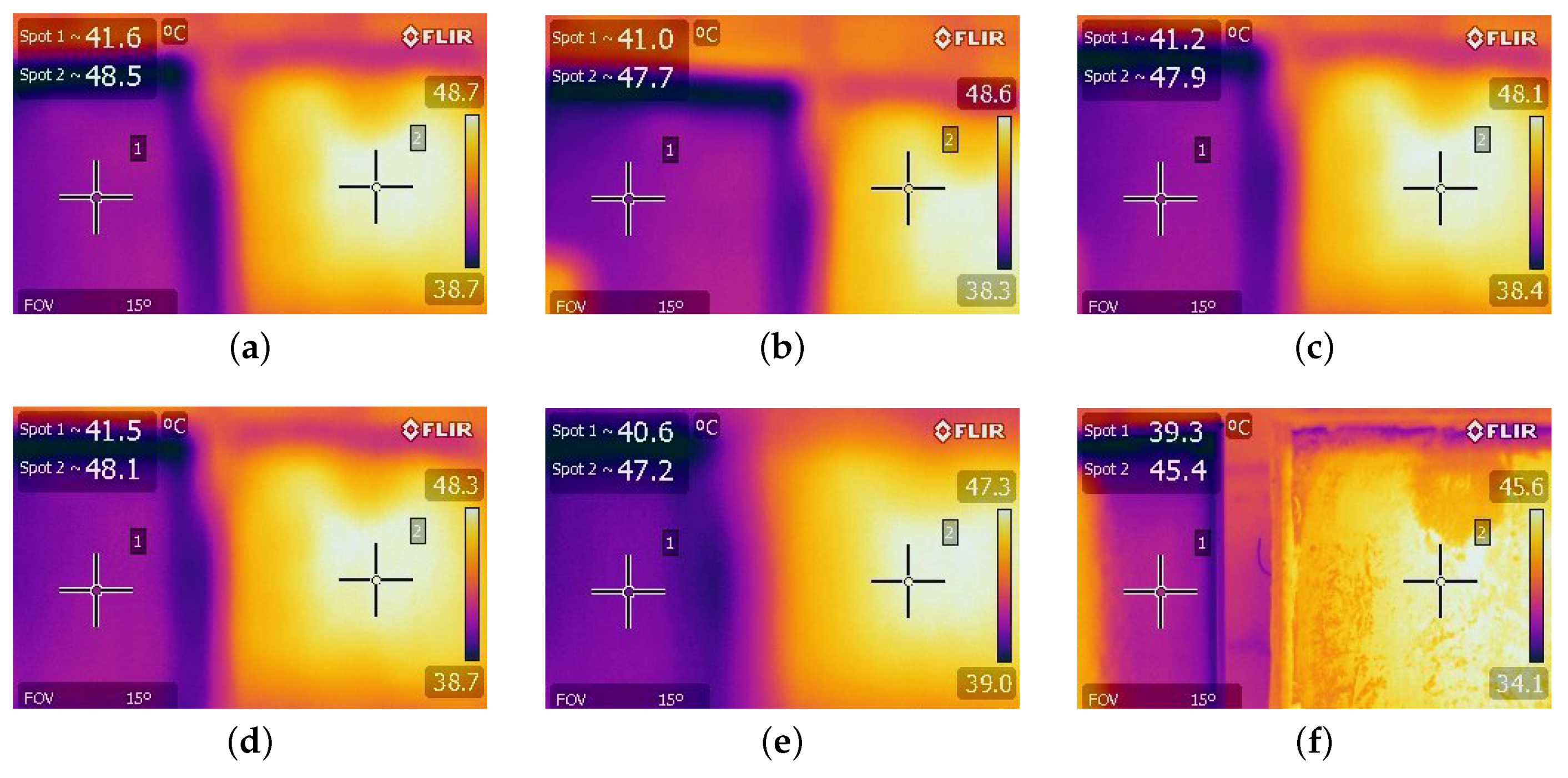
| 14:00 | 41.6 | 47.9 | 48.5 | 41.6 |
| 14:30 | 41 | 47.2 | 47.7 | 41.3 |
| 15:00 | 41.2 | 46.9 | 47.9 | 40.9 |
| 15:30 | 41.5 | 47.1 | 48.1 | 41.5 |
| 16:00 | 40.6 | 46.8 | 47.2 | 41.1 |
| 16:30 | 39.3 | 46.4 | 45.4 | 40.9 |
© 2020 by the authors. Licensee MDPI, Basel, Switzerland. This article is an open access article distributed under the terms and conditions of the Creative Commons Attribution (CC BY) license (http://creativecommons.org/licenses/by/4.0/).
Share and Cite
Elavarasan, R.M.; Velmurugan, K.; Subramaniam, U.; Kumar, A.R.; Almakhles, D. Experimental Investigations Conducted for the Characteristic Study of OM29 Phase Change Material and Its Incorporation in Photovoltaic Panel. Energies 2020, 13, 897. https://0-doi-org.brum.beds.ac.uk/10.3390/en13040897
Elavarasan RM, Velmurugan K, Subramaniam U, Kumar AR, Almakhles D. Experimental Investigations Conducted for the Characteristic Study of OM29 Phase Change Material and Its Incorporation in Photovoltaic Panel. Energies. 2020; 13(4):897. https://0-doi-org.brum.beds.ac.uk/10.3390/en13040897
Chicago/Turabian StyleElavarasan, Rajvikram Madurai, Karthikeyan Velmurugan, Umashankar Subramaniam, A Rakesh Kumar, and Dhafer Almakhles. 2020. "Experimental Investigations Conducted for the Characteristic Study of OM29 Phase Change Material and Its Incorporation in Photovoltaic Panel" Energies 13, no. 4: 897. https://0-doi-org.brum.beds.ac.uk/10.3390/en13040897