Simulation-Based Methodology for Determining the Dynamic Strength of Tire Inflation Restraining Devices


1
Department of Machine Design and Research, Wrocław University of Science and Technology, Łukasiewicza 7/9, 50-371 Wroclaw, Poland
2
Faculty of Marine Engineering, Department of Machine Construction and Materials, Maritime University of Szczecin, Willowa 2, 71-650 Szczecin, Poland
*
Authors to whom correspondence should be addressed.
Energies 2020, 13(4), 991; https://0-doi-org.brum.beds.ac.uk/10.3390/en13040991
Submission received: 7 February 2020
/
Revised: 18 February 2020
/
Accepted: 20 February 2020
/
Published: 22 February 2020
(This article belongs to the Section D: Energy Storage and Application)
Abstract
:The article suggests and supports a simulation-based methodology for determining whether the dynamic strength of tire inflation restraining devices for tire inflation meet quality requirements and ensure operator safety during a potential tire explosion. Dynamic strength tests using an NM-600 safety shield and NK-0728 safety cage during a 29.5 R25X tire explosion at a pressure of 10 bar were presented as an example application of this methodology. The shield was subjected to destructive tests involving the use of a 2200 kg impactor, dropping it so that the minimum kinetic energy reached 20 kJ at the time of impact. Analyzed devices were constructed of S355 steel in accordance with EN 10025. The Cowper–Symonds model of material for strain rate phenomena was used in the calculations. Simulations of a 20 kJ ring impact against the cage were performed. The equivalent stress distribution was determined, and displacement contour lines for the maximum dynamic deformation value and plastic deformation were calculated. The plastic displacement obtained in numerical tests was equal to the permanent deformation recorded in the experimental test. Further, the simulations showed that the examined cage met the assumed strength criteria. The conducted tests confirmed the usefulness of the proposed methodology for assessing the dynamic strength of safety cages and shields for tire inflation. The full-scale, physical cage testing is difficult to implement because it requires placing a ring impacting the cage wall. This is a major boundary for closed cages, as considered in this publication. Thus, simulation-based methods are becoming a principal tool for safety assessment of tire inflation restraining devices.
1. Introduction
Explosions during tire inflation are one of the most significant hazards when servicing wheeled vehicles [1,2,3,4]. The risk increases as the energy of the tire pressure increases, i.e., as the wheel size and tire pressure increase [5,6,7]. An explosion may lead to serious head injury or the death of an operator [8,9,10,11,12]. Operators and mechanics working with agricultural, mining, construction, and building machinery, trans-shipment equipment, tractors, trucks, trailers, and semi-trailers are particularly at risk [13,14,15,16]. There are several documents currently available that list safety requirements during tire inflation [15,17], including standard guidelines for operator safety [18,19].
There are currently no universal international safety standards for large tire inflation, but the local requirements for the strength of the shields and safety rules have been presented in a number of documents [15,18,19,20]. For example, the standard referred to as US DoL OSHA 1910.177 [19] requires the use of a restraining device, which is defined as “an apparatus such as a cage, rack, assemblage of bars and other components that will constrain all rim wheel components during an explosive separation of a multi-piece rim wheel, or during the sudden release of the contained air of a single-piece rim wheel”. The US DoL OSHA 1917.44 standard [18] also states that: “Except as otherwise noted, inflation shall be done within a restraining device such as a cage, rack or other device capable of withstanding the maximum force that would be transferred to it during an explosive wheel separation occurring at 150% of maximum tire specification pressure for the wheels being serviced. The restraining device shall be capable of preventing rim components from being thrown outside the frame of the device for any wheel position within the device. When the wheel assembly is mounted on a vehicle, tires may be inflated without a restraining device only if they have more than 80% of the recommended pressure and if remote control inflation equipment is used and employees are clear of the danger area.”
There are several restraining devices that allow for the inflation of tires mounted on a vehicle, and for loose tires [21]. The first group includes safety shields, while the second group includes clamp-based devices, bag-type restraints, and safety cages [20].
The lack of standards and guidelines concerning testing methodology requirements and criteria for evaluating the restraining devices and supporting structures is a serious problem [22,23,24,25]. Destructive tests can be carried out using test loads for safety shields, but it is a significant challenge to carry out tests on safety cages because dynamic destructive forces during tire explosion act on the supporting structure from the cage interior. The development and use of dedicated equipment (impact hammers/strikers, ring launchers, etc.) for dynamic testing of a cage may be a solution to this problem; however, this is not economically viable due to the different designs of safety cages.
A literature analysis of possible hazards during a tire explosion [1] indicates that an assessment of this type of structure should be guided by an analysis of mechanical hazards [24,26]. Mechanical hazards in the case of tire inflation safety shields and safety cages are related to tire damage caused by the tire being inflated on the rim, or by the sliding of the protective ring [14,20]. In this case, the shield should provide protection against the effects of such incidents. There are a number of simulation-based methodologies that could be used for the analysis of different operational aspects of mechanical systems, including reliability and safety, as well as processes in solid-state materials and in fluids. Such tests might be performed in general by means of the Monte Carlo [27,28] method supported by Fault Tree Analysis (FTA) [29,30], Reliability Block Diagrams (RBD) [31,32], Accelerated Life Testing (ALT) [33], Computational Fluid Dynamics (CFD) [34,35] or the Finite Element Method (FEM) [24,36]. Following the specificity of the analyzed situation (explosion is rapid and extremally dynamic) and of the system that was taken into account (inflation restraining device to which solid-state mechanics are applied), the FEM-based analysis was taken into account as a candidate for the core of the proposed methodology. To sum up, the goal of this study is to develop a safety assessment methodology based on FEMSimulations of safety cages and shields.
Initial testing on a single tire inflation shield showed that the simulation results were consistent with a destructive test carried out using a test load. The approach suggested in this article will enable the verification of structural assumptions of safety cages, without requiring any destructive tests, which will reduce the time and cost of testing safety cages before they are permitted for use.
2. Methodology of Safety Cage Simulation Tests
Figure 1 shows the methodology used to evaluate the dynamic strength of safety cages, proposed and used by the authors in accordance with FEM [7,17,37,38,39]. This methodology allows the mechanical properties of a safety cage to be assessed during the impact of a ring with specified dimensions and impact energy, while taking into account material and geometrical non-linearities.
The use of this methodology was illustrated by an exemplary analysis of a 29.5 R25X tire and a Lena Wilkow NK-0728 cage. For the assumed material characteristics, as well as for the development of a geometric and discrete model of the cage, FEM calculations were conducted using LS-DYNA software (Livermore Software Technology Corporation, Livermore, CA, USA). The calculations were performed for the impact of the ring on the center of the cage, and for the side impact with the ring energy at the moment of impact equal to 20 kJ. For both cases, the following data were obtained: the time function at selected points of the shield, reduced stress contour lines, displacement contour lines, and deformation contour lines. Ultimately, the calculation results were analyzed, and conclusions were drawn regarding the safety of the operator during tire inflation when using the tested cage.
3. Destructive Test
To verify the FEM simulation results, destructive tests were performed. It was assumed that the shield support structure should be made as per the design specifications and meet the following requirements:
- All parts of the shield in the immediate vicinity of workers must be free of sharp corners and edges, and the shield’s texture may not pose an injury risk;
- Class 3 welded joints must be used, and defects found during external inspection should not exceed class W3.
The support structure of the NM-600 shield for wheel inflation meets requirements when the defectiveness of welded joints does not exceed class 3 and when the strain of the shield is insufficient to make it lose its protective function. There must also be no damage to welded joints.
The scope of experimental tests included:
- -
- Checking the dimensions according to design specification;
- -
- Testing the impact to the shield by an impactor;
- -
- Assessing the test impact effects.
The test rig for the dynamic test consisted of:
- A test impactor (Figure 2a) in the form of a steel cylinder with a diameter of 800 mm, a height of 525 mm, and a total mass of 2200 kg, which was placed vertically above the designated point of impact;
- A device to release the test impactor from a sling;
- An overhead crane to lift the test impactor to the required height above the protective shield being tested in order to obtain the required impact energy;
- A digital camera to record the dynamic test footage.
The support structure of the NM-600-wheel inflation shield was rested on the supports (equivalent to a frame), which comprised channel bars and tubular profiles laid on a horizontal concrete foundation. In the central sheath of the NM-600-wheel inflation shield, a circle with a 400 mm radius was mapped as a representation of the test impactor strike area.
Using a lifting device, a test impactor with a mass (m) of 2200 kg was raised vertically above the shield to a height (h) of 0.95 m. The kinetic energy at the time of impact from this height was obtained:
where g = 9.81 m/s2, the standard acceleration of gravity.
After the test impactor struck the shield’s sheathing, it was found that (Figure 2b):
- The NM-600-wheel inflation shield was not punctured at the impact point;
- The maximum permanent deformation of the sheathing was 50 mm, so the strain can be considered acceptable (Figure 2b);
- The supporting elements, hinges, and distance between the sheathing cross-bars did not significantly change;
- The welded joints of the shield were not visibly damaged;
- Neither the joint between the replacement frame nor the shield were affected.
4. Simulation Testing
4.1. Mathematical Model of the Material Properties
The following assumptions were made when calculating the forces acting during the impact of the sliding ring on the cage:
- ▪
- Ring (impactor) mass: 75 kg;
- ▪
- Outer diameter of the ring: 0.8 m;
- ▪
- Assumed tire pressure: 10 bar;
- ▪
- The path, determined by geometric conditions, on which the interaction between the wall and the ring occurs: 0.2 m.
The velocity at which the ring is projected depends on the interior pressure of the tire acting on its side. Since the side of the tire acts as a single lever when the ring is ejected, the force acting on the ring is approximately 50% of the force acting on the side of the tire. The maximum kinetic energy of the sliding ring at the assumed pressure is approximately 17.5 kJ. In the calculations, the kinetic energy was set to 20.0 kJ. For this reason, the velocity of the ring used in the calculations was 23.094 m/s at the moment of impact.
There are two types of static and dynamic characteristics that can be distinguished by using a behavior model for a material. The first one describes qualitative changes occurring in the material, and the second one takes into account both qualitative and quantitative changes related to viscosity. The dynamic characteristics of steel were presented in a previous article [40]. The structural materials of cages, mostly metals, display a variety of behaviors under external forces [37,41,42]. Depending on current and past forces, these materials may experience either plastic or elastic deformation, and they may also be subject to creep, have a strengthening effect, and exhibit elastic or plastic viscosity [37,43,44,45]. Thermodynamic effects are also important when specifying material properties. It can be seen that it is very difficult to fully describe the material characteristics under complex stress conditions over an entire range of force variations. It is possible, however, to simplify this model by recognizing the nature of the loads and the working conditions of the structure.
According to its documentation, the analyzed tire inflation safety cage is made out of S355 steel in accordance with EN 10025. The static material properties are as follows:
- Yield point Remin = 355 MPa;
- Tensile strength Rmmin = 490 ÷ 630 MPa;
- Elongation A5 = 20 ÷ 22%.
Several models of deformation behavior (quality changes) were used for numerical and analytical methods:
- (a)
- Elastic;
- (b)
- Elastic–plastic (bilinear);
- (c)
- Elastic–plastic (multilinear);
- (d)
- Elastic–perfectly plastic;
- (e)
- Rigid–plastic;
- (f)
- Rigid–perfectly plastic;
- (g)
- Models based on material characteristics .
The last group includes a power model (for the plastic part) and the Krupkowski model. The trilinear model of the material with a tangent module equal to ET = 11.95 × 10⁸ MPa, presented in Figure 3, was used for the calculations.
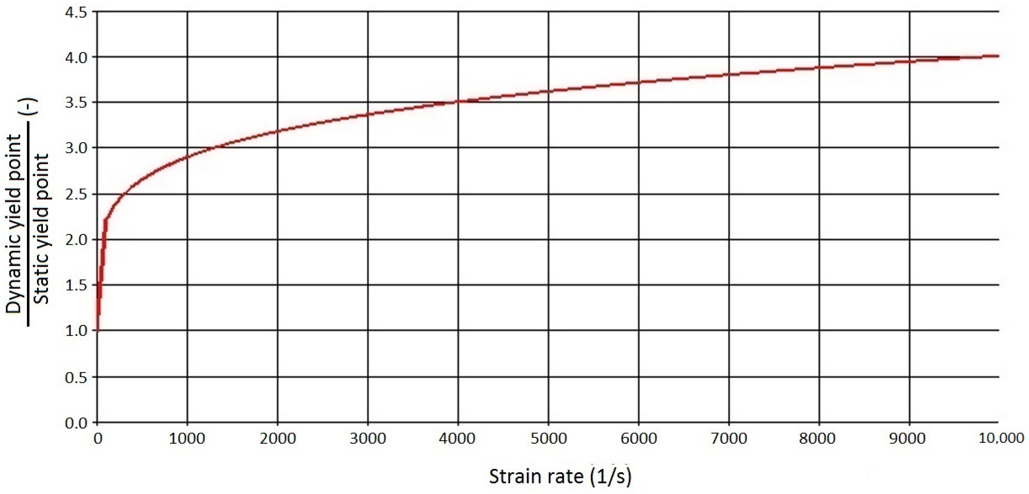
Considering the quantitative changes occurring in the material, i.e., strengthening with the strain rate, the obtained models were based on the assumed visco-plastic properties of the material. An extensive review of these models can be found in Perzyna’s articles [43,44,45]. The strain rate was distributed over the elastic strain rate and the viscoelastic strain rate :
while the stress value is:
where E is the elastic modulus.
In the Finite Element Method, the models based on the above model to describe the strengthening with the strain rate were:
- Cowper–Symonds model
- Johnson–Cook modelwhere: is the static yield point, and p, D are material constants.
Figure 4 shows the effect of strengthening on the dynamic yield point, as calculated using the Cowper–Symonds model.
4.2. Geometric and Discrete Models of Tire Inflation Restraining Devices
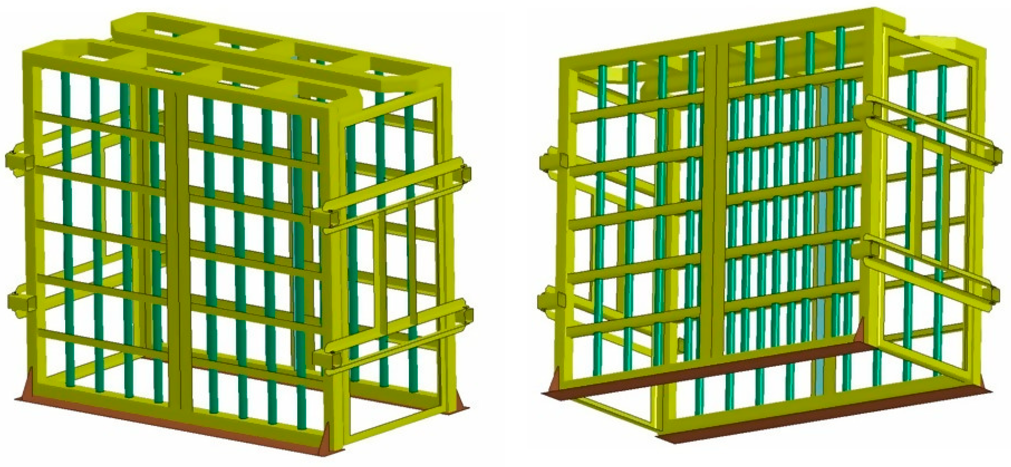
Based on the technical documentation of the safety cage structure, both a geometric model and a discrete model were developed. Strength calculations were carried out using the Finite Element Method. The calculations made it possible to determine the function of displacements, strain rate, and stress in particular elements of the load-bearing system, and the contour lines of displacements, stress, and deformations. The geometric models of the NM-600 safety shield and the NK-0728 safety cage are presented in Figure 5 and Figure 6.
For both types of safety devices, a discrete model was built and divided into finite elements. Non-linear strength FEM calculations of the superstructure were performed during verification testing over a dynamic range: the simulation of a ring impact with a mass of 75 kg and an energy of 20 kJ.
4.3. Impact on the Shield for Inflating Tires Fitted to a Vehicle
The shield’s characteristic points, for which the course of displacements has been determined over time, are shown in Figure 7.
The kinetic energy of the impactor was transferred to the shield after impact, and the maximum dynamic deformation occurred at the impact location (Figure 8 and Figure 9). The velocity of the impactor and the local velocity of the shield were then equalized, and the kinetic energy of the system was converted into the strain energy of the shielding. These phenomena can be seen in the displacement diagram (Figure 8).
The maximum dynamic deformation f1 of the shield was 92 mm for t = 12 ms. During the deformation, the material became plasticized (Figure 9), first in the area where the impactor struck the shield, and then in its posts. The permanent deformation at the impact point was approximately 50 mm.
4.4. Impact on the Cage During Loose Tire Inflation
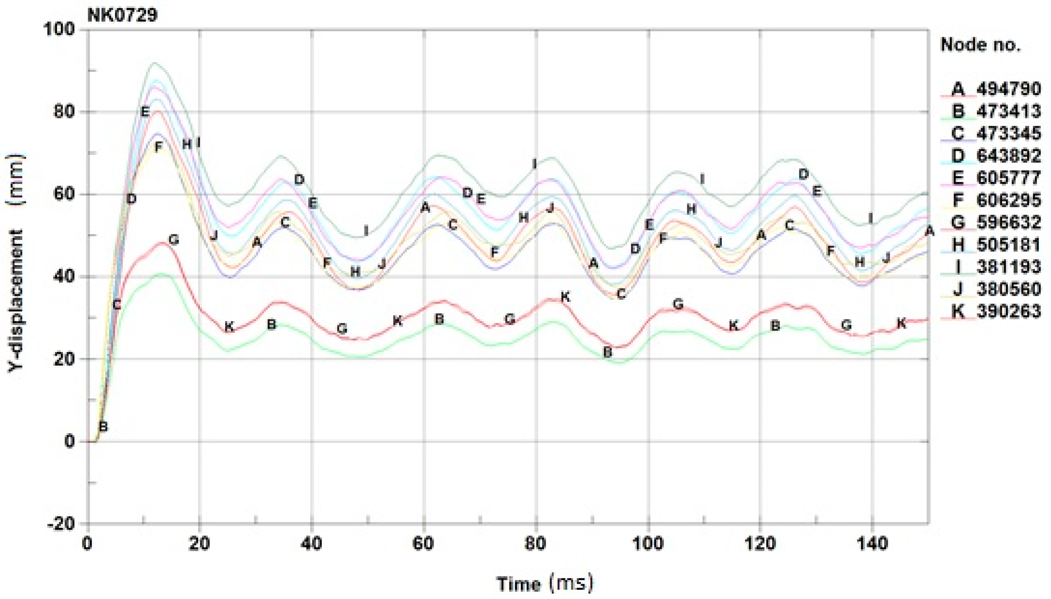
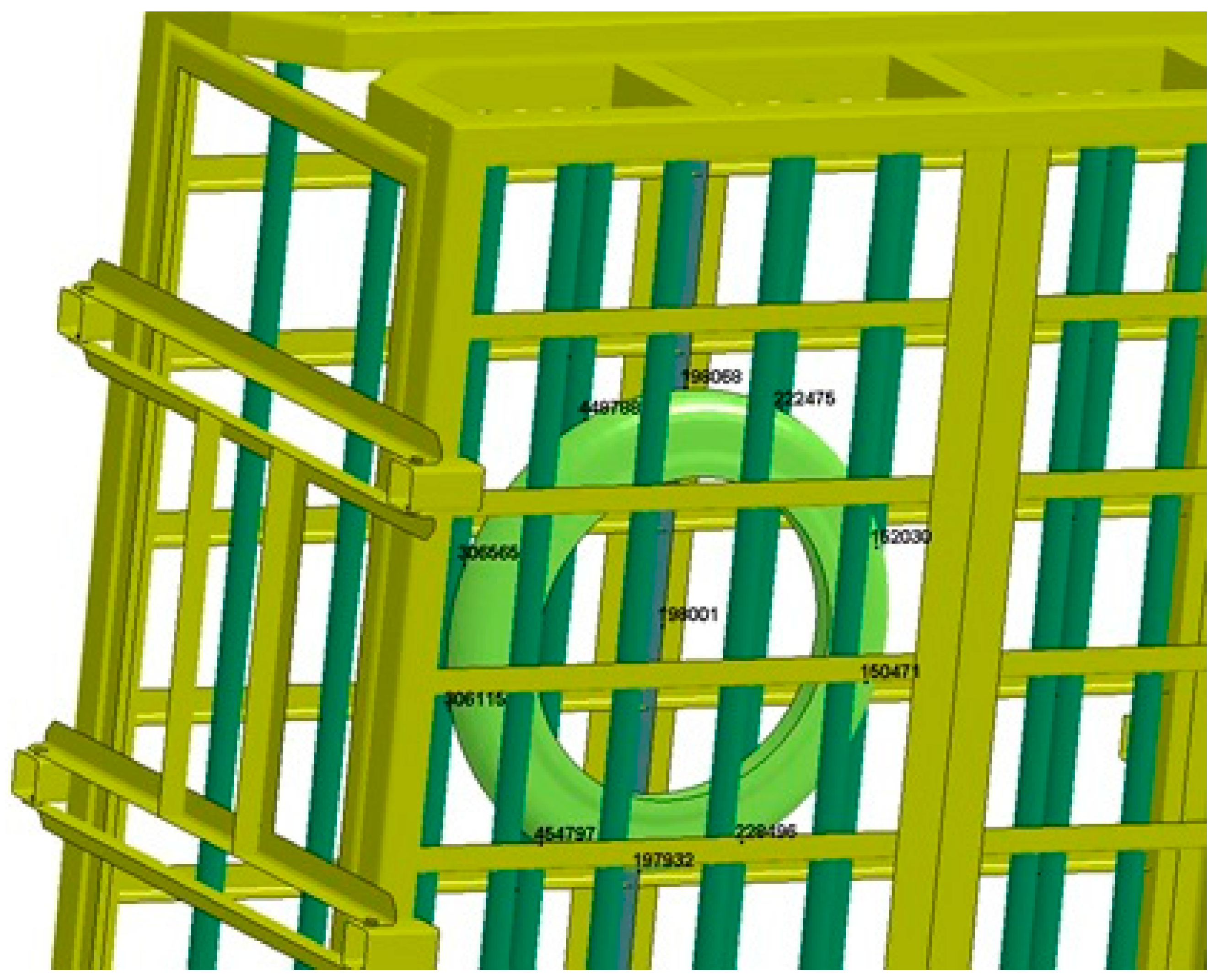
The characteristic points of the shield at which the function of time displacement was determined are both shown within the ring in Figure 10.
The kinetic energy of the impactor (the ring) was transferred to the shield after the moment of contact between the impactor and the shield. The velocity of the impactor and the shield was then locally balanced, and the kinetic energy of the system was converted into deformation energy of the shield. This can be seen in the displacement charts (Figure 11). The maximum plastic deformation occurred at the point of impact with the impactor (Figure 12).
The maximum dynamic deformation value of the shield was f1 = 103 mm for t = 46 ms. During deformation, the material became plasticized, initially at the area of contact between the impactor (the rim) and the shield and then in the columns. The permanent deformation at the impact point was approximately 60 mm.
5. Operator Safety Assessment
The support structure of the NM-600-wheel inflation shield was subjected to experimental destructive tests in accordance with the authors’ methodology, i.e., it was hit vertically by a free-falling test impactor with an energy equal to 20,503 kJ. The shield was not perforated or deformed in the plastic regime in such a way that the safety of its use was reduced, and there was no damage to the welded joints. It was found that the maximum permanent deformation was 50 mm. Therefore, the experiment confirmed that the NM-600-wheel inflation shield met the requirements in accordance with the standard.
Simulation tests of a shield for inflating wheels attached to a vehicle showed that the elastic deformation (deformation at the point of impact) of the shield, if struck on its center, was f1 = 92 mm, while the permanent deformation of the shield (deformation at the point of impact) was f1 = 50 mm. The plastic deformation obtained in simulation tests was equal to the permanent deformation obtained in experimental tests. The tests showed that the support structure of the tire inflation shield of a tire fitted to a vehicle was not damaged under loads resulting from an impact of a 75 kg ring with a kinetic energy of 20 kJ.
Neither the strain caused by the elastic deformation of the shield frame nor permanent deformation pose a threat to rig operators if operators maintain a minimum distance of 250 mm from shield elements during inflation. If anchors are used that bear minimum loads of 160 kN related to tension and 60 kN related to shear, the anchorage of the shield will not be damaged.
The strength analysis of the loose tire inflation cage revealed that the elastic deformation value (deformation at impact) of the cage in the event of an impact on the cage center was f1 = 103 mm, while the plastic deformation of the shield (deformation at impact) was f1 = 60 mm.
The simulations showed that the load-bearing structure of the tested cage for loose tire inflation was not breached at loads resulting from the impact of a 75 kg ring with a kinetic energy of 20 kJ.
Maximum elastic deformation of the shield frame—as well as permanent deformation—did not pose any threat to the station operators, provided the operator maintained a minimum distance of 250 mm from the shield components during inflation. The obtained results demonstrated that the tested cage meets the quality criteria and provides the required operator safety during vehicle tire inflation.
6. Conclusions
The conducted tests showed that the safety shield meets the assumed quality criteria. The agreement between the physical experiment and the FEM simulation results confirmed the usefulness of the simulation methods. This is particularly important in relation to potential testing of safety cages, which are difficult to test in real-life conditions since a ring must be positioned inside a cage before it strikes the cage wall (in the case of cages for inflating wheels demounted from vehicles or work machines).
In this publication, the authors investigated the case where the securing ring is slipping out from the wheel’s rim. This was considered as the worst-case scenario for the operator’s safety since the ring behaves as a projectile, with kinetic energy up to 20.0 kJ. Unlike the tire outburst, the ring acts on a small surface of the cage’s wall, which implies the stress concentration in the cage structure. The conducted tests confirmed the usefulness of the proposed methodology for assessing the dynamic strength of a safety cage for tire inflation. Full-scale, physical, experimental cage testing is difficult to implement because it requires placing a ring impacting the cage wall. This is a major boundary for experimental testing, especially for closed cages, as considered in this publication.
Finite Element Simulations proved to be useful for evaluating the compliance of a safety cage with specified quality criteria. The additional advantage of simulation testing is the possibility of performing multiple analyses using the same cage model, examining the strength at different ring impact points, which requires multiple cages during experimental testing due to their damage in each test. During experimental testing, it is difficult to apply a specific dynamic force at a precise location, and this may require an application of specially designed impact hammers/strikers or an explosion test in controlled conditions [46]. However, these approaches are very expensive compared to numerical tests, and experimental testing requires suitable safeguards and security procedures, which limit its universality.
The strength testing methods presented in this article can be used for testing various types of cages. Due to the lack of detailed quality criteria standards in the case of tire inflation restraining devices, and minimal quantitative requirements in the case of permissible mechanical deformations, the methodology presented in this article supported by other simulation-based methodologies (e.g., those mentioned in the introduction) may serve as the basis for the development of such standards in the future.
Author Contributions
Conceptualization, J.K., M.P., and L.C.; methodology, J.K., M.P., and L.C.; software, J.K., M.P., and L.C.; validation, J.K., M.P., and L.C.; formal analysis, J.K., M.P., and L.C.; investigation, J.K., M.P., and L.C.; resources, J.K., M.P., and L.C.; data curation, J.K., M.P., and L.C.; writing—original draft preparation, J.K., M.P., and L.C.; writing—review and editing, J.K., M.P., and L.C.; visualization, J.K., M.P., and L.C.; supervision, J.K., M.P., and L.C.; project administration, J.K., M.P., and L.C.; funding acquisition, J.K., M.P., and L.C. All authors have read and agree to the published version of the manuscript.
Funding
The publication was developed as part of the project “Strength analysis of safety shield for wheel pumping” (Wroclaw University of Science and Technology, reports 045/2013 and 046/2013), as well as the project LIDER/8/0051/L-8/16/NCBR/2017 funded by the National Centre for Research and Development, Poland, and Grant 1/S/IESO/17 (commenced at the Maritime University of Szczecin).
Conflicts of Interest
The authors declare no conflict of interest. The funders had no role in the design of the study; in the collection, analyses, or interpretation of data; in the writing of the manuscript; or in the decision to publish the results.
References
- Karliński, J.; Ptak, M.; Chybowski, L. A Numerical Analysis of the Working Machine Tyre Inflation Process to Ensure Operator Safety. Energies 2019, 12, 2971. [Google Scholar] [CrossRef] [Green Version]
- Karliński, J.; Ptak, M.; Działak, P.; Rusiński, E. The approach to mining safety improvement: Accident analysis of an underground machine operator. Arch. Civ. Mech. Eng. 2016, 16, 503–512. [Google Scholar] [CrossRef]
- Bahn, S. Workplace hazard identification and management: The case of an underground mining operation. Saf. Sci. 2013, 57, 129–137. [Google Scholar] [CrossRef]
- Karliński, J.; Ptak, M.; Działak, P. Assessment of Safety Cages for Tire Replacement and Inflation. In Proceedings of the Automotive Safety Conference, Rajeckie Teplice, Slovakia, 8–10 April 2014. [Google Scholar]
- Chybowski, L.; Gawdzińska, K.; Ślesicki, O.; Patejuk, K.; Nowosad, G. An engine room simulator as an educational tool for marine engineers relating to explosion and fire prevention of marine diesel engines. Sci. J. Marit. Univ. Szczecin Zesz. Nauk. Akad. Morskiej w Szczecinie 2015, 43, 15–21. [Google Scholar]
- Chybowski, L.; Kazienko, D. The Development of an Explosion Protection System in the Starting Air Manifold of a High Power Engine. Syst. Saf. Hum. Tech. Facil. Environ. 2019, 1, 26–34. [Google Scholar] [CrossRef] [Green Version]
- Baranowski, P.; Bogusz, P.; Gotowicki, P.; Małachowski, J. Assessment of Mechanical Properties of Offroad Vehicle Tire: Coupons Testing and FE Model Development. Acta Mech. Autom. 2012, 6, 17–22. [Google Scholar]
- Kaczyński, P.; Ptak, M.; AO Fernandes, F.; Chybowski, L.; Wilhelm, J.; J Alves de Sousa, R. Development and Testing of Advanced Cork Composite Sandwiches for Energy-Absorbing Structures. Materials 2019, 12, 697. [Google Scholar] [CrossRef] [Green Version]
- Ratajczak, M.; Ptak, M.; Chybowski, L.; Gawdzińska, K.; Będziński, R. Material and Structural Modeling Aspects of Brain Tissue Deformation under Dynamic Loads. Materials 2019, 12, 271. [Google Scholar] [CrossRef] [Green Version]
- Ptak, M. Method to Assess and Enhance Vulnerable Road User Safety during Impact Loading. Appl. Sci. 2019, 9, 1000. [Google Scholar] [CrossRef] [Green Version]
- Hefny, A.F.; Eid, H.O.; Abu-Zidan, F.M. Severe tyre blast injuries during servicing. Injury 2009, 40, 484–487. [Google Scholar] [CrossRef]
- Murty, O.P. Tyre-blast injuries. J. Forensic Leg. Med. 2009, 16, 224–227. [Google Scholar] [CrossRef] [PubMed]
- Karliński, J.; Ptak, M.; Działak, P. Ocena bezpieczeństwa osłon do pompowania kół. Transp. Przem. Masz. Rob. 2014, 2, 153–158. [Google Scholar]
- Guo, H.; Bastien, C.; Blundell, M.; Wood, G. Development of a detailed aircraft tyre finite element model for safety assessment. Mater. Des. 2014, 53, 902–909. [Google Scholar] [CrossRef]
- Goverinment of Western Australia. Department of Mines and Petroleum Use of tyre inflation cages. Mines Saf. Bull. 2015, 122. Montreal, Canada. [Google Scholar]
- Benoit, R. Heavy Vehicles Tire Blowout and Explosion; IRSST: Montreal, QC, Canada, 2009. [Google Scholar]
- Jeong, K.M. Prediction of Burst Pressure of a Radial Truck Tire Using Finite Element Analysis. World J. Eng. Technol. 2016, 04, 228–237. [Google Scholar] [CrossRef] [Green Version]
- United States Department of Labor. Servicing multi-piece and single piece rim wheels. In Occupational Safety and Health Administration Standard 1910.177; OSHA: Washington, DC, USA, 2011. [Google Scholar]
- United States Department of Labor. General rules applicable to vehicles. In Occupational Safety and Health Administration Standard 1917.44; OSHA: Washington, DC, USA, 2011.
- Health and Safety Executive. Safety during Tyre Inflation in Motor Vehicle Repair; HSE: Suffolk, UK, 2010.
- Helth and Safety Executive. Health and Safety in Motor Vehicle Repair and Associated Industries; II; Crown: London, UK, 2011; ISBN 9780717663088.
- Rusiński, E.; Czmochowski, J.; Smolnicki, T. Advanced Finite Element Method for Load-Carrying Structures of Machines; Publishing House of Wrocław University of Technology: Wrocław, Poland, 2000; ISBN 8370854583. [Google Scholar]
- Karliński, J.; Rusiński, E.; Smolnicki, T. Protective structures for construction and mining machine operators. Autom. Constr. 2008, 17, 232–244. [Google Scholar] [CrossRef]
- Derlukiewicz, D.; Ptak, M.; Wilhelm, J.; Jakubowski, K. The numerical-experimental studies of demolition machine operator work. In Lecture Notes in Mechanical Engineering; Springer: Cham, Switzerland, 2017; Volume Part F10, pp. 109–120. [Google Scholar]
- Nozdrzykowski, K.; Chybowski, L. A Force-Sensor-Based Method to Eliminate Deformation of Large Crankshafts during Measurements of Their Geometric Condition. Sensors 2019, 19, 3507. [Google Scholar] [CrossRef] [Green Version]
- Chybowski, L. Safety criterion in assessing the importance of an element in the complex technological system reliability structure. Manag. Syst. Prod. Eng. 2012, 1, 10–13. [Google Scholar]
- Chybowski, L.; Gawdzińska, K. A stochastic simulation-based component importance analysis for complex technical systems. Probl. Eksploat. Maint. Probl. J. Mach. Constr. Maint. 2017, 17, 47–50. [Google Scholar]
- Gucma, L.; Gucma, M.; Perkovič, M.; Vidmar, P. Simulation method for risk assessment in LNG terminal design. In Proceedings of the Sustainable Maritime Transportation and Exploitation of Sea Resources—Proceedings of the 14th International Congress of the International Maritime Association of the Mediterranean, Genova, Italy, 13–16 September 2011; Taylor & Francis Group, CRC Press: London, UK, 2012; Volume 1, pp. 755–776. [Google Scholar]
- Shafiee, M.; Enjema, E.; Kolios, A. An Integrated FTA-FMEA Model for Risk Analysis of Engineering Systems: A Case Study of Subsea Blowout Preventers. Appl. Sci. 2019, 9, 1192. [Google Scholar] [CrossRef] [Green Version]
- Chybowski, L. Importance Analysis of Components of a Multi-Operational-State Power System Using Fault Tree Models. Information 2020, 11, 29. [Google Scholar] [CrossRef] [Green Version]
- Kim, M.C. Reliability block diagram with general gates and its application to system reliability analysis. Ann. Nucl. Energy 2011, 38, 2456–2461. [Google Scholar] [CrossRef]
- Chybowski, L.; Żółkiewski, S. Basic reliability structures of complex technical systems. Adv. Intell. Syst. Comput. 2015, 354, 333–342. [Google Scholar]
- ReliaSoft Corporation. Accelerated Life Testing Reference; Reliasoft Corporation: Tucson, AZ, USA, 2015. [Google Scholar]
- Hansen, O.R.; Hinze, P.; Engel, D.; Davis, S. Using computational fluid dynamics (CFD) for blast wave predictions. J. Loss Prev. Process Ind. 2010, 23, 885–906. [Google Scholar] [CrossRef]
- Díaz-Ovalle, C. A CFD-based Approach to Predict Explosion Overpressure: A Comparison to Current Methods. Chem. Biochem. Eng. Q. J. 2017, 30, 419–427. [Google Scholar] [CrossRef]
- Chybowski, L.; Grządziel, Z.; Gawdzińska, K. Simulation and Experimental Studies of a Multi-Tubular Floating Sea Wave Damper. Energies 2018, 11, 1012. [Google Scholar] [CrossRef] [Green Version]
- Gawdzińska, K.; Chybowski, L.; Przetakiewicz, W. Study of Thermal Properties of Cast Metal- Ceramic Composite Foams. Arch. Foundry Eng. 2017, 17, 47–50. [Google Scholar] [CrossRef] [Green Version]
- Rusiński, E.; Moczko, P.; Odyjas, P.; Pietrusiak, D. Investigation of vibrations of a main centrifugal fan used in mine ventilation. Arch. Civ. Mech. Eng. 2014, 14, 569–579. [Google Scholar] [CrossRef]
- Ptak, M.; Ratajczak, M.; Kwiatkowski, A.; Sawicki, M.; Wilhelm, J.; Fernandesa, F.A.O.; Druszcz, A. Investigation of biomechanics of skull structures damages caused by dynamic loads. Acta Bioeng. Biomech. 2019, 21. [Google Scholar] [CrossRef]
- Wierzbicki, T. Obliczanie Konstrukcji Obciążonych Dynamicznie; Arkady: Warsaw, Poland, 1980. [Google Scholar]
- Gawdzińska, K.; Chybowski, L.; Przetakiewicz, W.; Laskowski, R. Application of FMEA in the Quality Estimation of Metal Matrix Composite Castings Produced by Squeeze Infiltration. Arch. Metall. Mater. 2017, 62, 2171–2182. [Google Scholar] [CrossRef] [Green Version]
- Gawdzińska, K.; Chybowski, L.; Przetakiewicz, W. Proper matrix-reinforcement bonding in cast metal matrix composites as a factor of their good quality. Arch. Civ. Mech. Eng. 2016, 16, 553–563. [Google Scholar] [CrossRef]
- Perzyna, P. Fundamental Problems in Viscoplasticity. Adv. Appl. Mech. 1966, 9, 243–377. [Google Scholar]
- Perzyna, P. Thermo-Elasto-Viscoplasticity and Damage. In Handbook of Materials Behavior Models; Academic Press: Cambridge, MA, USA, 2001. [Google Scholar]
- Perzyna, P. Constitutive modeling of dissipative solids for postcritical behavior and fracture. J. Eng. Mater. Technol. Trans. ASME 1984, 106, 410–419. [Google Scholar] [CrossRef]
- Earthmover Tire Cage Test 8/23/2012. Ken-Tool. Available online: https://www.youtube.com/watch?v=HANwJp8Z5mc (accessed on 29 January 2020).
Figure 1.
Simulation-based process for evaluating the dynamic strength of tire inflation restraining devices.
Figure 1.
Simulation-based process for evaluating the dynamic strength of tire inflation restraining devices.

Figure 2.
Destructive test preparation and results: (a) test impactor raised by the overhead crane above the tested shield; (b) measurement of the maximum plastic displacement of the front face of the shield.
Figure 2.
Destructive test preparation and results: (a) test impactor raised by the overhead crane above the tested shield; (b) measurement of the maximum plastic displacement of the front face of the shield.

Figure 3.
Trilinear elastic–plastic model of the material.

Figure 4.
Influence of the strain rate on the dynamic yield point.

Figure 5.
Geometric model of the shield for inflating wheels fitted to a vehicle—general overview.

Figure 6.
Overview of the geometric model of the safety cage used for loose tire inflation.

Figure 7.
Selected points of the shield after an impact on the shield.

Figure 8.
Displacement diagram over time for selected points of the shield for the impact on its center.
Figure 8.
Displacement diagram over time for selected points of the shield for the impact on its center.

Figure 9.
Reduced stresses according to Huber–Mises hypothesis (GPa) for maximum deformation—impact on the center of the shield.
Figure 9.
Reduced stresses according to Huber–Mises hypothesis (GPa) for maximum deformation—impact on the center of the shield.

Figure 10.
Selected points of the protective shield structure—impact in the middle of the cage.

Figure 11.
Diagram of displacement over time at selected points of the structure for an impact in the center of the cage.
Figure 11.
Diagram of displacement over time at selected points of the structure for an impact in the center of the cage.

Figure 12.
Reduced stress for the maximum displacement value of a cage center impact [GPa] calculated using the Huber–Mieses–Hencky hypothesis.
Figure 12.
Reduced stress for the maximum displacement value of a cage center impact [GPa] calculated using the Huber–Mieses–Hencky hypothesis.

© 2020 by the authors. Licensee MDPI, Basel, Switzerland. This article is an open access article distributed under the terms and conditions of the Creative Commons Attribution (CC BY) license (http://creativecommons.org/licenses/by/4.0/).
Share and Cite
MDPI and ACS Style
Karliński, J.; Ptak, M.; Chybowski, L. Simulation-Based Methodology for Determining the Dynamic Strength of Tire Inflation Restraining Devices. Energies 2020, 13, 991. https://0-doi-org.brum.beds.ac.uk/10.3390/en13040991
AMA Style
Karliński J, Ptak M, Chybowski L. Simulation-Based Methodology for Determining the Dynamic Strength of Tire Inflation Restraining Devices. Energies. 2020; 13(4):991. https://0-doi-org.brum.beds.ac.uk/10.3390/en13040991
Chicago/Turabian StyleKarliński, Jacek, Mariusz Ptak, and Leszek Chybowski. 2020. "Simulation-Based Methodology for Determining the Dynamic Strength of Tire Inflation Restraining Devices" Energies 13, no. 4: 991. https://0-doi-org.brum.beds.ac.uk/10.3390/en13040991
Note that from the first issue of 2016, this journal uses article numbers instead of page numbers. See further details here.