Applications of Triple Active Bridge Converter for Future Grid and Integrated Energy Systems


Department of Electrical Engineering and Computer Science, Tokyo Metropolitan University, Tokyo 192-0397, Japan
*
Author to whom correspondence should be addressed.
Energies 2020, 13(7), 1577; https://0-doi-org.brum.beds.ac.uk/10.3390/en13071577
Submission received: 27 February 2020
/
Revised: 17 March 2020
/
Accepted: 20 March 2020
/
Published: 1 April 2020
(This article belongs to the Special Issue Integration of Renewables in Power Systems by Multi-Energy System Interaction)
Abstract
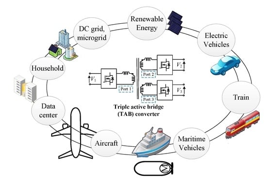
:Renewable energy systems and electric vehicles (EVs) are receiving much attention in industrial and scholarly communities owing to their roles in reducing pollutant emissions. Integrated energy systems (IES), which connect different types of renewable energies and storages, have become common in many applications, such as the grid-connected photovoltaic (PV) and battery systems, fuel cells and battery/supercapacitor in EVs. The advantages of all energy sources are maximized by utilizing connection and control strategies. Because many storage systems and household loads are mainly direct current (DC) types, the DC grid has considerable potential for increasing the efficiency of distribution grids in the future. In IES and future DC grid systems, the triple active bridge (TAB) converter is an isolated bidirectional DC-DC converter that has many advantages as a core circuit. Therefore, this paper reviews the characteristics of the TAB converter in current applications and suggests next-generation applications. First, the characteristics and operation modes of the TAB converter are introduced. An overview of all current applications of the TAB converter is then presented. The advantages and challenges of the TAB converter in each application are discussed. Thereafter, the potential future applications of the TAB converter with an adaptable power transmission design are presented.
1. Introduction
In current years, renewable energy systems and electric vehicles (EVs) have been increasingly used [1,2,3,4,5,6]. Renewable energy systems include, but are not limited to, photovoltaic (PV), wind power, biomass, hydro, and geothermal systems. The rooftop PV system is a common and essential energy source for residential loads. Other than battery EVs and hybrid EVs (HEVs), many fuel cell EVs (FCEVs) are also developed and implemented [7,8,9]. However, the fuel cells have the disadvantage of a slow transient response. Therefore, the battery or supercapacitor is used to adapt to the fast response in EVs and other applications [10]. EVs may use a lithium-ion battery, supercapacitor, fuel cell, or their integration to optimize power density. By connecting different types of energy and storage, electrical systems become integrated energy systems (IES) [11]. For example, a household electrical system connects PV, EVs, and/or storage systems. The EVs use integrated fuel cells, and/or batteries, and/or supercapacitors. The IESs can then optimize the advantages of all the energy systems. Therefore, this type of IES will be developed more in the future.
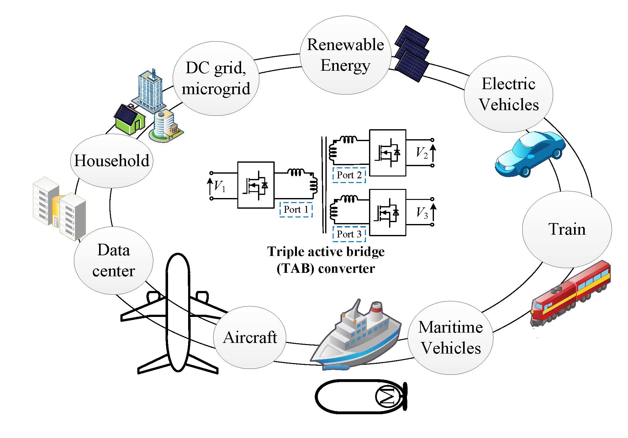
Direct current (DC) grids offer many advantages over alternating current (AC) grids, such as potentially higher efficiencies, and reduced filter effort [12,13,14]. DC-DC converters are one of the most important technologies for future DC grids. They offer precise control ability for power flow with high reliability. Dual active bridge (DAB), an isolated bidirectional dc-dc converter, has been proposed for many applications [15,16]. The DAB converter includes two full-bridge inverters that are connected by an isolation transformer at high-frequency operation, as shown in Figure 1. It has advantages such as a bidirectional power flow with high efficiency. However, it can only connect two ports; thus, many DAB converters need to be used to connect different elements to the DC-bus in the IES. Moreover, it may require a communication bus to control power flow.
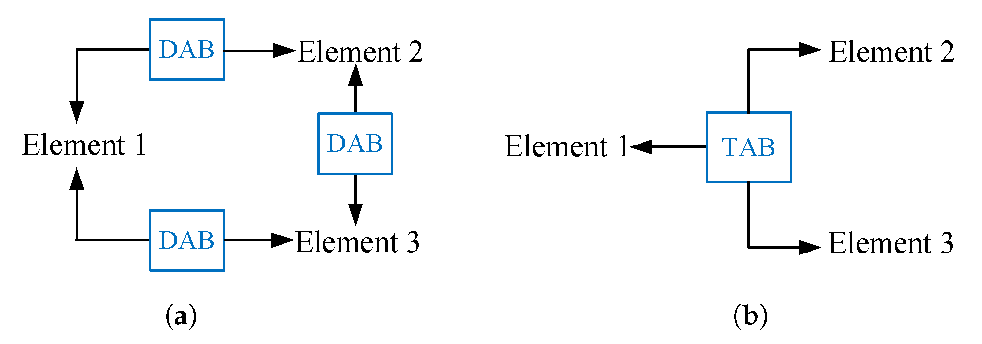
Therefore, the triple-active-bridge (TAB) converter was proposed to connect one more element by adding one more port to the DAB converter, as shown in Figure 2 [17]. The advantages of the DAB converter can be kept in the TAB converter. Moreover, it is not only applicable to one more port but also enables flexible power transmission between three ports, as shown in Figure 3. This shows that three DAB converters are required in Figure 3 to achieve flexible power transmission between three elements, which is achieved by only one TAB converter in Figure 3b. Also, the communication between the three elements is not necessary when using the TAB converter. Therefore, the control of the total system is more straightforward. In addition, in comparison to other multiport converters, the TAB converter has the advantage by using a transformer, which not only converts the voltage ratio but also improves the safety of the system. Therefore, the TAB converter is proposed for many applications in IES and DC grid.
Because there is an increase in the number and types of microgrids [18,19], the TAB converter is proposed to develop micro-grid systems, as shown in [20,21,22,23,24,25]. The future DC grid has potential in household applications, for which the TAB converter has an advantage [19,20,21,22]. It can be used to connect medium and low voltages in the DC distribution grid [26,27,28,29,30]. An uninterruptible power supply (UPS), which uses a battery to support the source in the worst-case scenario, is a suitable application for the TAB converter [31,32,33]. The TAB converter was discussed as an important part that can improve the reliability of the distribution system in the data center [34,35]. The proposed system in EVs applications is discussed in [36,37,38,39,40].
However, researches on the TAB converter focuses on each separated application and characteristic. It loses an overview of the current status, such as the advantages and challenges of the TAB converter in current applications. Also, there are many new applications such as all electrical ships, autonomous underwater vehicles, etc., that involve replacing other energy systems with electricity. Therefore, this paper presents an overview of current applications. The advantages and challenges of the TAB converter in different applications are analyzed. Then, future applications, which use storage systems, are suggested for use with the TAB converter. Also, potential applications and concepts in next-generation applications are proposed. This becomes a reference for researchers and engineers in the related topic for improving the TAB converter in current applications and extending applications.
2. Characteristics of the TAB Converter
2.1. Configuration and Model
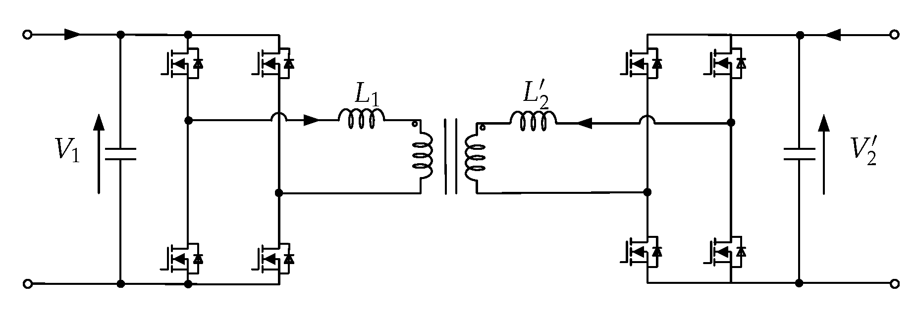
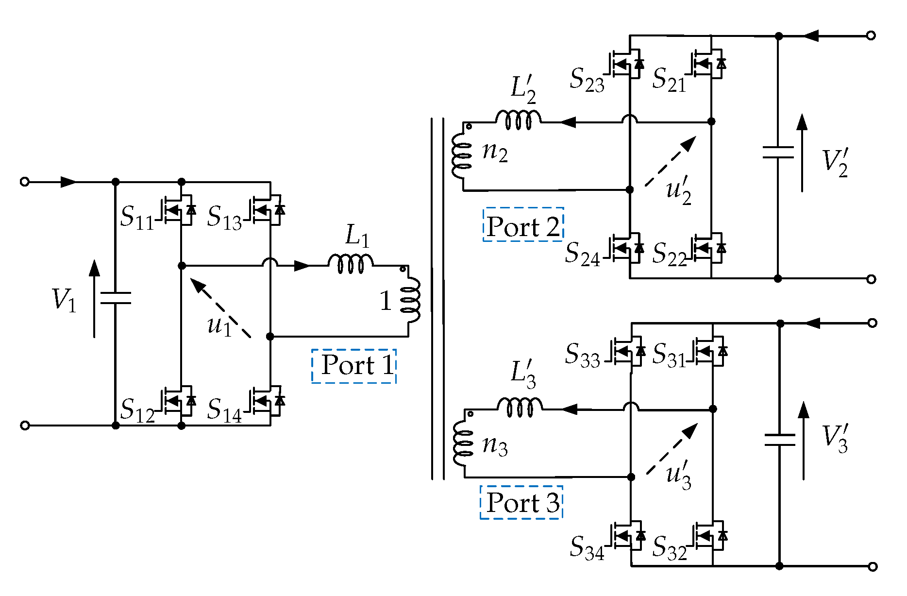
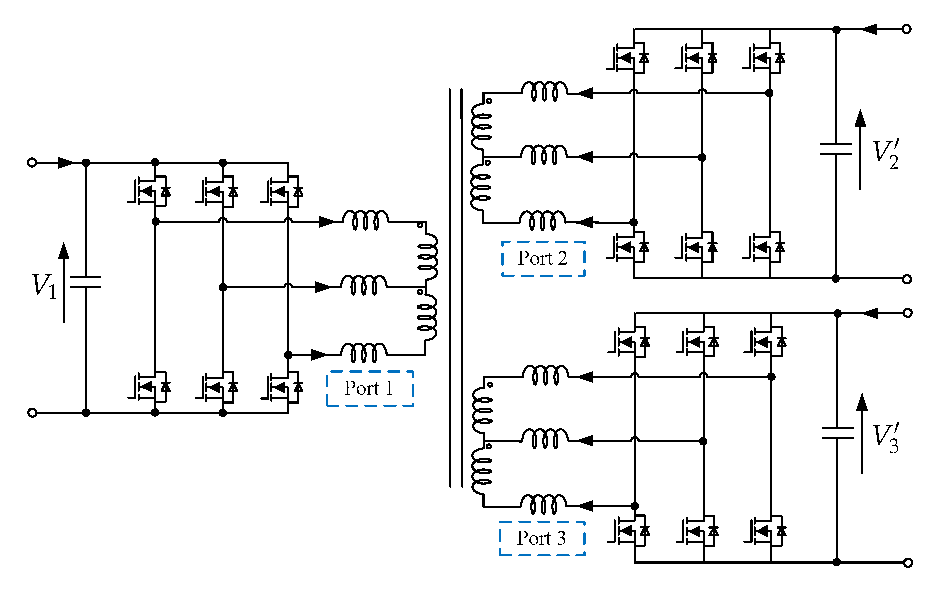
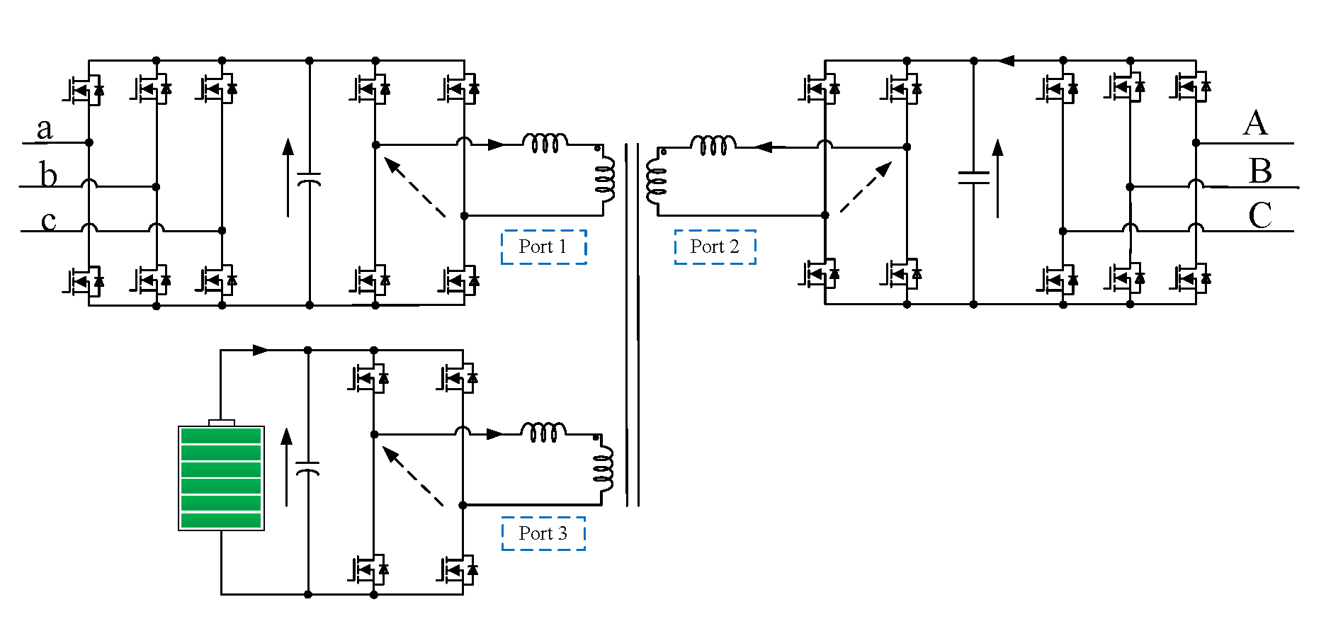
Figure 2 shows the circuit diagram of the TAB converter. It includes a three-winding transformer connecting port-1, port-2 and port-3. Each port has an inductance connected in series, and a full bridge inverter. The series inductances, , , and include the leakage and external inductances on each port. The symbols and are the turn ratios of the port-2 and port-3. The phase voltages between the leg midpoints of each port, , , and , have the amplitudes , , and , respectively. to , to , and to are the control signals of ports -1, -2 and -3, respectively. Figure 4 shows a three-phase TAB converter made by adding one switching leg to each inverter [41]. It is proposed for high power applications. Each phase of the three-phase TAB converter can be modeled as a single-phase TAB converter [26,41].
Figure 5 shows Y-type and -type equivalent circuits of the TAB converter, respectively [40]. The voltages and currents of the port-2 and port-3 refer to the port-1 as the following equation.
where and are the port-1-referred voltages, and and are the port-1-referred currents, respectively. Thus, it has the following equation.
where and are port-1-referred inductances, and and are port-1-referred voltage amplitudes, respectively.
2.2. Power Transmission and Control Methods
Based on the above model, the power transmission of the TAB converter is expressed by the following equations.
where , , and are the transmission powers of the of ports-1, -2, and -3, respectively. f is the switching frequency of the converter. and are phase shift angles on the port-2, and port-3 with reference to the port-1, respectively.
Therefore, the power transmission ability of each port can be controlled by two-phase shift angles, and , as shown in Figure 6a. The phase shift angles between , , and decide amplitude and direction of the transmission power among the three ports [21,22,23,24,25]. The decoupling matrix is implemented into the control loop to remove the interference among the ports [25,40]. Besides, the combined duty cycles and two-phase shift angles methods were discussed to improve the efficiency of the TAB converter, as shown in Figure 6b [38,39,40,42]. , , and are duty cycle variations of , , and , respectively. This technique can extend the soft switching at light load but it reduces the power transmission ability of the converter [42]. Furthermore, upon adding more variables to the system, the control system and calculation of the controller become more complex. Therefore, the two-phase shift angles method is widely used for controlling the TAB converter in many applications. The combined duty cycle and two-phase shift angles method can be considered for applications that usually operate under light load condition.
2.3. Operation Mode and Characteristics
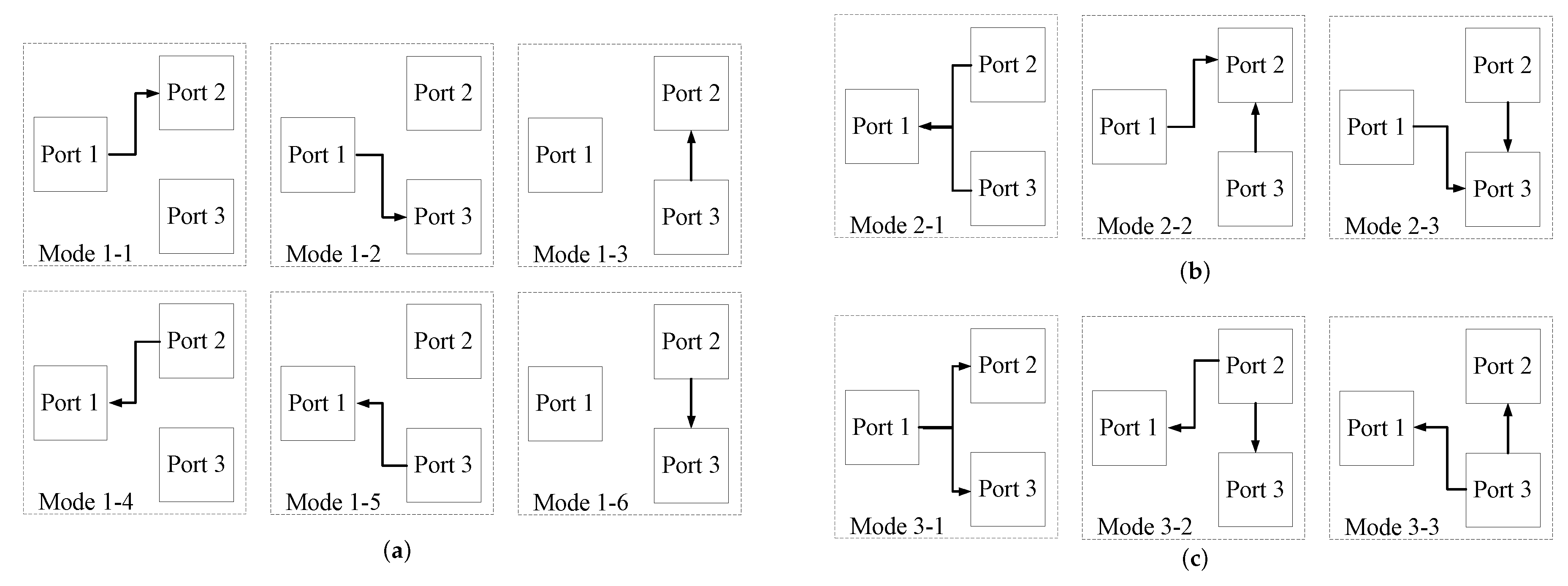
By controlling the phase shift angles, the TAB converter has many working operation modes, as shown in Figure 7.
It can be categorized into three groups. The single input single output (SISO) modes when the power comes from one port to another while the third port does not get power. The dual input single output (DISO) modes, which supplies power to one port from the other two ports. The single input dual output (SIDO) modes when power from one port is supplied to the two other ports. This shows the flexible power transmission ability of the TAB converter.
Figure 8 shows the phase shift operation of the TAB converter in all operation modes by using two phase-shift angles. The horizontal and vertical axes show the phase shift values of port 2 and port 3, and , respectively. The phase shift angles are decided by the operating power, inductance values, and voltages as the relationship in (2)–(4). The series inductances are important elements of the TAB converter. A normalized design method for the inductances was discussed in [21,22]. Voltage variations, which are in many applications, need to be considered in operation modes. Figure 8a shows the phase shift operation when the voltages of the three ports are all 100%. Figure 8b shows the phase shift operation when and are both 100%, whereas is 80%. It shows that the SISO modes are the most critical in the design and control of the TAB converter, where the phase-shift angles are the largest.
The experimental waveform of each port in operation mode 1-2 is shown in Figure 9 to explain the characteristic in one of the most critical operation modes. The figure shows that the root mean square (RMS) and peak current of port 2, , are much higher in the voltage variation condition. In this case, the combined duty cycle and phase shift control can be applied to reduce the RMS and peak currents of port 2 [38,39,40,42].
3. Current Applications of TAB Converter
3.1. Microgrids
A microgrid is an integrated system that combines sources, storage systems, and loads [18,19]. The DC bus Microgrid systems using TAB converter were discussed in [20,21,22]. Figure 10 shows the comparison of a DC bus microgrid using the TAB converter and the conventional converter. It shows that the system using the TAB converter can reduce the required number of DC-DC converters and communication lines. Consequently, the cost of the system is reduced.. The rapidly increasing use of the EVs will bring much change in household electrical systems in the future. The DC household electrical system is discussed in [19]. The TAB converter can be used in household electrical systems for a power range of 10 kilowat (kW), as discussed in [21,22]. The EVs or storage can be charged from the grid or directly from the rooftop PV. In addition, EVs have a high-power battery, which can be a storage and support system for the household load or grid [5]. By using the TAB converter, the DC bus microgrid system becomes more flexible in setup and more optional in operation, which are advantages.
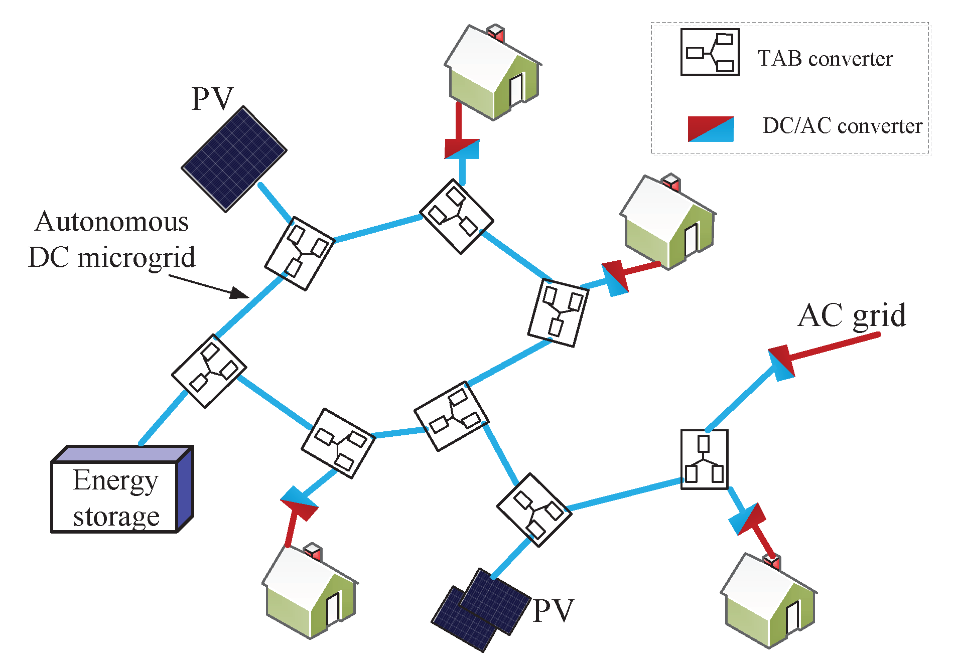
An autonomous DC microgrid using the TAB converter is proposed in [23,24,25], as shown in Figure 11. One port of the TAB converter is connected to one element, and the remaining two ports are connected to the autonomous DC microgrid to control the power and voltage. The TAB converter can change the control target to keep a constant voltage and for different loads depending on the condition of the system. The transformers of the TAB converters isolate all the parts of the microgrid. Therefore, if one element has an error, other elements still work well, and the system is easy to extend at any time. The DC/AC converter can be added to a port that connects to an AC load or source. This idea can be applied to the traditional microgrid system when some elements are used to improve reliability. In the future microgrid system, the TAB converter is a promising circuit when combining two above systems.
3.2. Connection of Medium Voltage Grid and Low Voltage Grid
The medium voltage DC (MVDC) grid has recently created a need for the investigation of the concept of the DC distribution grid [43,44,45]. The overall stability and efficiency of the DC grid are increased by controlling the power flow [26]. Therefore, a three-phase TAB converter is proposed for the MVDC grid in [26,27,28,29,30], as shown in Figure 12. The nominal voltage of the MVDC grid is 5 kV. Two LVDC grids work at 380 V and 760 V, respectively. The 760 V LVDC grid is examined as a ±380 V LVDC grid. The TAB converter can use all operation modes in Figure 7 for this application because the power is required to be transferred in any direction among the three ports. It can operate as an equal three DAB converter as shown in the comparison in Figure 3. Therefore, the system can reduce the number of components and costs by using the TAB converter. In typical operation, the power mainly comes from MVDC to LVDC as the operation modes 1-1, 1-2, and 3-1. However, in some critical situations, the remaining operation modes of the TAB converter can be used for this application. Then, three grids can support each other. This shows that the TAB converter can be optimally utilized for all operation modes in this application.
A three-phase TAB converter rated 150 kW is designed to connect 5 kV MVDC and two LVDC sources in [26,27,28,29,30]. The modulation strategy and transformer design are considered to operate at a rated power [26]. The soft-switching limitation in each port is analyzed. Subsequently, a parallel-phase operation (PPO) is proposed to extend the soft-switching component of the converter [27]. All ports achieve soft switching by applying the multiport duty cycle method. The current and voltage measurements require isolation to the MVDC part, as discussed in [28]. The dynamic of the current control loop is discussed in [29]. The instantaneous current control is applied to the TAB converter to achieve a high dynamic power response. The challenges of using the 1200 V SiC MOSFET for the TAB converter in MVDC and LVDC is discussed in [30].
Other configurations, which can connect multiple single-phase TAB converters, can also be applied to interconnect MVDC and LVDC, as shown in Figure 13 [46,47,48]. It can connect two ports in series and one port in parallel to connect two MVDC grids and one LVDC grid, as shown in Figure 13a. Figure 13b shows the system which connects one port in series and two ports in parallel to connect one MVDC grid and two LVDC grids. The number of modules is selected depending on the available semiconductor devices and operating voltage. The insulated-gate bipolar transistor (IGBT) devices rated 4.5 kV are considered for high voltage applications. More research to utilize the devices and voltage range of each module should be discussed more in the future.
3.3. Uninterrupted Power Supply Systems
The TAB converter was proposed for the uninterrupted power supply (UPS) systems [31,32], as shown in Figure 14. The power source, load, and battery are connected using one TAB converter as discussed in [31,32], where the power source and electric load may require a frequency isolation of 50 Hz and 60 Hz, respectively. The system operates typically in the mode 1-1. However, all remaining modes can be used in an abnormal situation. By using a TAB converter with a three-winding transformer, the safety of the system is improved. The operation of the system is flexible with simple control.
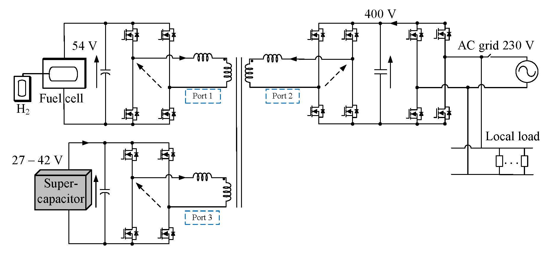
A UPS system powered by a fuel cell is proposed by using a TAB converter in [33,42,49], as shown in Figure 15. The system is flexible and can work on grid-connected or stand-alone modes. The fuel cells have a slow transient response, which is a drawback. The supercapacitor can be used as storage to support the fuel cells to respond quickly in transient time. Depending on the load and the status of the supercapacitor and fuel cell, it may operate in different modes. This could be discussed more in the future. For high power applications, the three-phase TAB converter can also be used. In low power applications, the half-bridge TAB converter is suitable [50]. This shows that the TAB converter is an excellent selection for these proposed systems where all operation modes are achieved by one converter.
3.4. Power Distribution for Data Center
The reliability of the distribution systems for data centers is of the most importance points. Interruptions of power systems in the data center have the high cost of millions of dollars an hour [51]. Therefore, the TAB converter was proposed to improve the reliability and availability of power distribution of data centers in [34,35], as shown in Figure 16. This system can operate as a UPS system to prevent power faults in distribution systems of the data center. The number of converters can be reduced by sharing a battery between two distribution lines. Consequently, using the TAB converter can reduce the cost of the system. Furthermore, two distribution lines can support each other in a critical situation. Therefore, all operation modes of the TAB converter can be used in this application, which maximizes the advantages of the TAB converter.
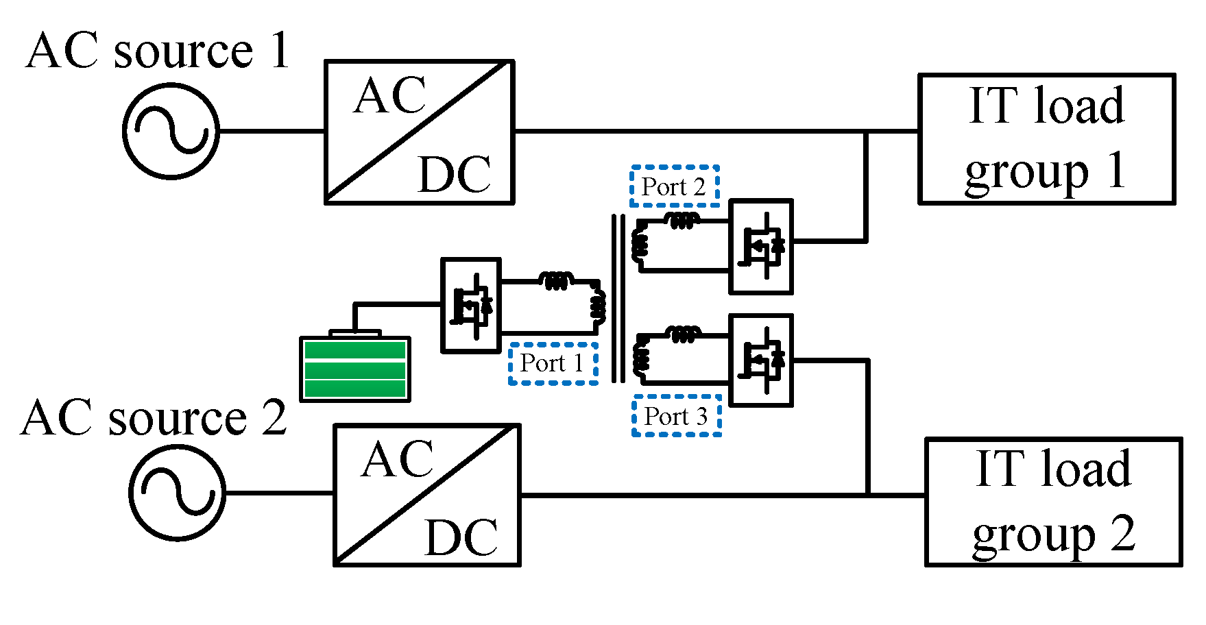
Typically, the data center distribution system has many independent loads. The power requirement at a time is different for each load. Some loads may require high power while others need low power. Balancing the load can improve the sustainability of the system. In order to improve the reliability of the data center distribution system, the TAB converter was proposed to share the power between the distribution lines in [52], as shown in Figure 17. The power distribution in each load group is evaluated. The TAB converter balances the power load for the data center system. This can improve the reliability of the system from 96.00% to 97.53%. Therefore, the TAB converter is a promising candidate in this application. However, the stability and accuracy will be the challenge for controlling the TAB converter in this application because of high-reliability requirements.
3.5. Electric Vehicles
Electric vehicles (EVs) normally have a high voltage (HV) battery of 300 V–400 V and a low voltage (LV) battery of 14 V [53]. The HV battery supplies the main power for the motor. The LV battery supplies power for other facilities such as the fan, light, wiper, radio, etc. The on-board charger is implemented in EVs to charge the EVs at home with a power range of 3–6 kW. Therefore, the DC-DC converter and charger are combined using the TAB converter as shown in Figure 18 [36,37,38,39]. The port-1 is connected to the main battery. The port-2 is connected to the low voltage battery. The port-3 is connected to the DC source after the rectifier from the AC grid. The two DC-DC converters in the conventional system are combined by using one TAB converter. This reduces the components, size, and cost of the system. However, the idling isolation of the charger port is a challenge in this application. Therefore, phase shift combined duty cycles are proposed for this condition to reduce the peak and RMS current [36,37,38,39,40]. This shows that this method can be applied in other applications that have a similar critical condition.
The 42 V bus for EVs was discussed in [40] to increase the power for HEVs. Therefore, the electrical system may have three voltage levels (14 V/42 V/400 V). The TAB converter has many advantages for this system because it separates voltage levels using one converter with a three-winding transformers, as shown in Figure 19. The power can be supplied from three storage systems effectively during start-up or regular running. This shows that all the operation modes of the TAB converter can be applied in this application to maximize the power and lifetime of the system. In the future, the studies on optimal power and operation modes for each condition of the system can be discussed more.
3.6. More Electric Aircraft
Beside electric vehicles, the more electric aircraft (MEA) has been widely researched and discussed to reduce emissions in the world [54,55]. The electrical system in MEA requires improved efficiency, reliability, and reduced implementation costs. The electrical system usually uses a 230 V AC voltage and two DC voltages, of 270 V and 28 V, respectively. The auxiliary power unit (APU) is used to supply power when the MEA is on the ground. It can use a battery and fuel cell system of 270 V or 540 V [55,56,57]. The battery can also be used for emergency situations, to store energy in low load conditions, and support in heavy load conditions. Therefore, the TAB is proposed to regulate power flow in MEAs in [58], as shown in Figure 20. Two DC voltages and APU are connected and supported by one TAB converter and a centralized control system.
Using the TAB converter is an advantage because the power between three elements always works together to achieve high safety and reliability of this application. However, high current and high power design and control are the challenges of this application. More research and verification should be discussed in detail in the future.
4. Future Applications with Battery
In recent years, there have been many new applications which aim to use more electricity as the main energy. There are many types of batteries and techniques that are developing to connect many cells in series and parallel for the high power applications [59,60,61,62]. Therefore, this part aims to propose the TAB converter for new potential applications which use the storage system.
4.1. Autonomous Underwater Vehicles
The autonomous underwater vehicles (AUVs) have spread widely in recent years [63,64,65]. The size and weight of the AUVs are limited, and the data can be corrected if the AUVs can work for a long time. Therefore, the power system of the AUVs is a challenge. The Lithium-ion battery is used for AUVs because of its high power density [63]. The fuel cell system for AUVs is discussed to extend their working time [64]. The integrated fuel cell and battery systems for AUVs have been discussed in recent times [65]. This can achieve a higher power density, which reduces the number of the batteries and increases the power for the AUVs. With the many advantages in the integrated power system, the TAB converter is a promising candidate for this application. A TAB converter can be connected directly between the motor driver (M), fuel cell, and battery, as shown in Figure 21.
It can use a 48 V battery with a capacity of 34 Ah for a small AUVs [65]. A fuel cell can install a 48 V system. The converter operates at 1 to 3 kW. However, this application requires high efficiency and small size. To realize a large power AUVs system, the system can be implemented with an optimal design of the TAB converter, depending on the battery and fuel cell system.
4.2. All-Electric Ships
All-electric ships (AESs) are developed to improve the efficiency of energy in the ships [66,67]. The advantages of MVDC distribution for all-electric ships (AESs) was discussed in [68]. By using MVDC (1–8 kV) distribution, the motor is not connected to a fixed-frequency system and can be designed and operated to maximize efficiency. The advantage of the battery energy storage system (BESS) for the ship was discussed in [69]. Therefore, the electrical ship is a promising application of the TAB converter in the future, as shown in Figure 22.
The battery and supercapacitor can be charged by regenerative energy in the light load condition, and then used for supporting in the heavy load condition. It stabilizes the voltage and current of the electrical grid in the ship. Additionally, the battery and supercapacitor are useful auxiliary power systems for rapid-starting in booster or electric-motor modes. Depending on the size and type of ship, the power system may range from 500 kW to several megawatt. The storage capacity is selected depending on the control strategy. It can be implemented by the 400 V storage system. The TAB converter for AESs application may work at several hundred kW, which is challenged by the high voltage high power design.
5. Future Applications for Controlling Power Flow
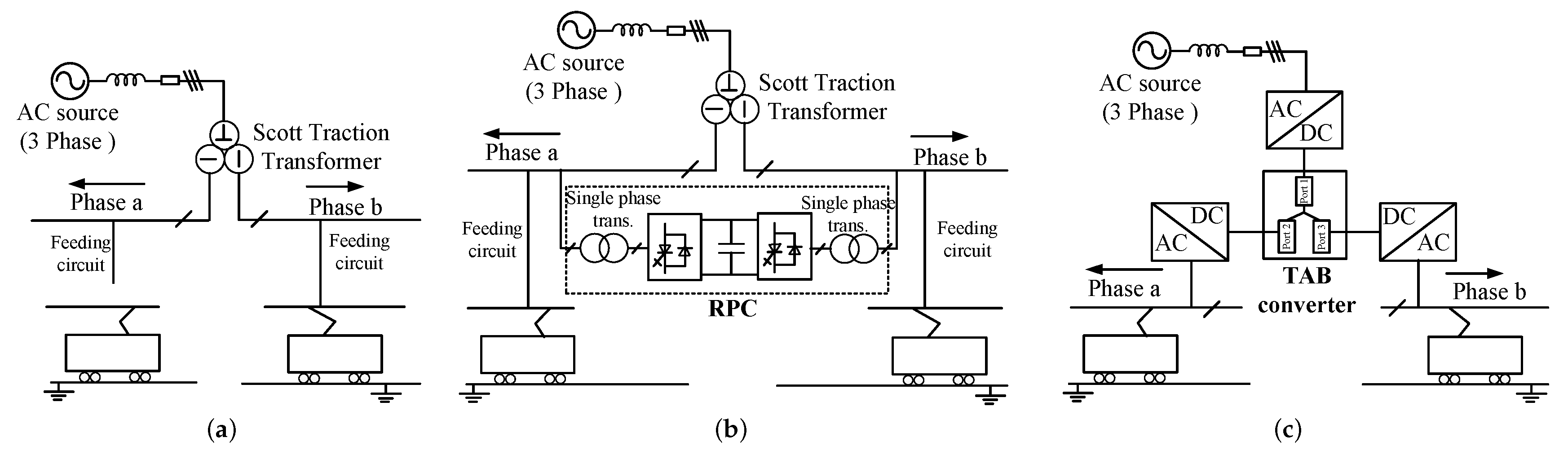
The AC power utility system for a railway, for example, shinkansen in Japan, uses two single-phase AC voltages 25 kV or 20 kV for two direction lines [70,71,72]. The single-phase AC voltages are supplied from a three-phase voltage using a Scott-connected transformer, as shown in Figure 23a. The electric power load of each single-phase voltage may be unbalanced depending on the number and position of the trains in each direction. This affects the three-phase voltage side, which causes a more significant voltage fluctuation. Therefore, a railway static power conditioner (RPC) is developed to control voltage fluctuation on the three-phase voltage side in [72], as shown in Figure 23b. An RPC is constructed from two pulse width modulation (PWM) inverters, which are connected by a large DC link capacitor system. The other side of each inverter is connected to a single-phase voltage by a single-phase transformer.
In this way, the two inverters can work as a static synchronous compensator (STATCOM), and the reactive power is compensated by feeding an active power from one bus to another. The power utility system then needs a scott traction transformer, two inverters, two single-phase transformers, and a DC link capacitor system. Both the Scott transformer and RPC have large-capacity, high weight, and big size.
In this paper, a future concept is suggested for application in the future railway utility by using the TAB converter, as shown in Figure 23c. A TAB converter, which connected 160 kV DC voltage from the rectifier and two 44 kV DC voltages outputs for the train system. It can replace both the Scott transformer and RPC to achieve isolation and power flow control targets. The size, components, and cost are reduced. The reactive power from the load also is compensated. With this new concept, the power of each phase of the AC source is balanced, which improves the stability and reliability of the grid. The connection of many TAB converters in the module can be suggested to solve the challenges of very high voltage and power.
6. Summary and Discussion
The above sections reviewed current applications and proposed new applications of the TAB converter. This section gives a summary all applications of the TAB converter. The advantage and challenges of each application are summarized, as shown in Table 1. For each application, the TAB converter contributes to the different targets to develop conventional systems. There are also different challenges in each application, which also need more development in the future. The normal and abnormal operation modes are listed. It shows that some applications use all operation modes such as distribution systems for data center and more electric aircraft, where the TAB converter is a good selection because of saving cost and improving the reliability. Some applications do not use all operation modes. However, by using the TAB converter, it not only reduces the component but also extends the functionality of the system.
In the future, research into the TAB converter can go in two directions. Firstly, new studies can focus on solving the general issues of the TAB converter. This can have an impact on one or many applications. Secondary, the new investigation can solve a challenge in each application also is the contribution. This suggests that also the new trend of semiconductors and the magnetic components can be discussed to improve the TAB converter. It is also necessary to undertake further study of the TAB converter in these applications, which are high power and high voltage/current.
7. Conclusions
The TAB converter is considered a promising circuit for next-generation DC grid and integrated energy systems, which have vast market prospects. The advantages of the TAB converter include multiple interfacing ports with isolation, achievable implementation of centralized controls, and improved flexibility of electric systems. This paper reviewed the characteristics of the TAB converter and the research status of the current applications. The paper also showed that the TAB converter could be an upgraded solution for conventional systems. Additionally, some potential future applications with the battery were presented. A future concept for AC voltage railway systems was also proposed. The design and performance optimization of the TAB converter for high power applications with high reliability will be the trend in the future.
Author Contributions
V.-L.P. analyzed the operation and characteristics of the TAB converter; V.-L.P. summarized the current applications of the TAB converter; two authors actively proposed new applications of the TAB converter. The paper was written by V.-L.P.; two authors actively participated in revising the paper; the paper was supervised by K.W.; All authors have read and agreed to the published version of the manuscript.
Funding
This research received no external funding.
Conflicts of Interest
The authors declare no conflict of interest.
Abbreviations
The following abbreviations are used in this manuscript:
| MDPI | Multidisciplinary Digital Publishing Institute |
| DOAJ | Directory of open access journals |
| TLA | Three letter acronym |
| LD | linear dichroism |
References
- Chan, C.C. The State of the Art of Electric, Hybrid, and Fuel Cell Vehicles. Proc. IEEE 2007, 95, 704–718. [Google Scholar] [CrossRef]
- Huang, A.Q.; Crow, M.L.; Heydt, G.T.; Zheng, J.P.; Dale, S.J. The Future Renewable Electric Energy Delivery and Management (FREEDM) System: The Energy Internet. Proc. IEEE 2011, 9, 133–148. [Google Scholar] [CrossRef]
- Blaabjerg, F.; Teodorescu, R.; Liserre, M.; Timbus, A.V. Overview of Control and Grid Synchronization for Distributed Power Generation Systems. IEEE Trans. Ind. Electron. 2006, 53, 1398–1409. [Google Scholar] [CrossRef] [Green Version]
- Kim, J.; Yu, C.J.; Khammuang, M.; Lui, J.; Almujahid, A.; Daim, T. Forecasting Battery Electric Vehicles. In Proceedings of the 2017 IEEE Technology & Engineering Management Conference (TEMSCON), Santa Clara, CA, USA, 8–10 June 2017. [Google Scholar]
- Yilmaz, M.; Krein, P.T. Review of the Impact of Vehicle-to-Grid Technologies on Distribution Systems and Utility Interfaces. IEEE Trans. Power Electron. 2013, 28, 5673–5689. [Google Scholar] [CrossRef]
- Longo, M.; Yaïci, W.; Foiadelli, F. Electric Vehicle Charge with Residential’s Roof Solar Photovoltaic System: A Case Study in Ottawa. In Proceedings of the 2017 IEEE 6th International Conference on Renewable Energy Research and Applications (ICRERA), San Diego, CA, USA, 5–8 November 2017; pp. 121–125. [Google Scholar]
- Sharaf, O.Z.; Orhan, M.F. An overview of fuel cell technology: Fundamentals and applications. Renew. Sustain. Energy Rev. 2014, 32, 810–853. [Google Scholar] [CrossRef]
- He, H.; Zhang, Y.; Wan, F. Control strategies design for a fuel cell hybrid electric vehicle. In Proceedings of the IEEE Vehicle Power and Propulsion Conference, Harbin, China, 3–5 September 2008; pp. 1–6. [Google Scholar]
- US Department of Energy. The Department of Energy Hydrogen and Fuel Cells Program Plan; An integrated strategic plan for the research, development, and demonstration of hydrogen and fuel cell technologies; US Department of Energy: Washington, DC, USA, 2011.
- Gao, W. Performance comparison of a fuel cell-battery hybrid powertrain and a fuel cell-ultracapacitor hybrid powertrain. In Proceedings of the Power Electronics in Transportation (IEEE Cat. No.04TH8756), Novi, MI, USA, 21–22 October 2004; pp. 143–150. [Google Scholar]
- Shivarama Krishna, K.; Sathish Kumar, K. A review on hybrid renewable energy systems. Renew. Sustain. Energy Rev. 2015, 52, 907–916. [Google Scholar] [CrossRef]
- Planas, E.; Andreu, J.; Gárate, J.I.; De Alegría, I.M.; Ibarra, E. AC and DC Technology in Microgrids: A Review. Renew. Sustain. Energy Rev. 2015, 43, 726–749. [Google Scholar] [CrossRef]
- Wunder, B.; Ott, L.; Szpek, M.; Boeke, U.; Weis, R. Energy efficient dc-grids for commercial buildings. In Proceedings of the Telecommunications Energy Conference (INTELEC), Vancouver, BC, Canada, 28 September–2 October 2014; pp. 1–8. [Google Scholar]
- Boeke, U.; Wei, R.; Mauder, A.; Hamilton, L.; Ott, L. Efficiency Advantages of ±380 v dc Grids in Comparison with 230 v/400 v ac Grids. Available online: http://dcgrid.tue.nl/files/DCC_G_D6_1_Public_summary_V1_0.pdf (accessed on 27 February 2020).
- Inoue, S.; Akagi, H. A Bidirectional Isolated DC–DC Converter as a Core Circuit of the Next-Generation Medium-Voltage Power Conversion System. IEEE Trans. Power Electron. 2007, 22, 535–542. [Google Scholar] [CrossRef]
- Zhao, B.; Song, Q.; Liu, W.; Sun, Y. Overview of Dual-Active-Bridge Isolated Bidirectional DC–DC Converter for High-Frequency-Link Power-Conversion System. IEEE Trans. Power Electron. 2014, 29, 4091–4106. [Google Scholar] [CrossRef]
- Duarte, J.L.; Hendrix, M.; Simoes, M.G. Three-Port Bidirectional Converter for Hybrid Fuel Cell Systems. IEEE Trans. Power Electron. 2007, 22, 480–487. [Google Scholar] [CrossRef] [Green Version]
- Chowdhury, S.; Chowdhury, S.P.; Crossley, P. Microgrids and Active Distribution Networks, 1st ed.; IET: London, UK, 2009. [Google Scholar]
- Prabhala, V.A.; Baddipadiga, B.P.; Fajri, P.; Ferdowsi, M. An Overview of Direct Current Distribution System Architectures & Benefits. Energies 2018, 11, 2463. [Google Scholar]
- Kado, Y.; Shichijo, D.; Deguchi, I.; Iwama, N.; Kasashima, R.; Wada, K. Power flow control of three-way isolated DC/DC converter for Y-configuration power router. In Proceedings of the 2015 IEEE 2nd International Future Energy Electronics Conference (IFEEC), Taipei, Taiwan, 1–4 November 2015; pp. 1–5. [Google Scholar]
- Pham, V.-L.; Wada, K. Normalization Design of Inductances in Triple Active Bridge Converter for Household Renewable Energy System. IEEJ J. Ind. Appl. 2020, 9, 3. [Google Scholar]
- Pham, V.-L.; Wada, K. Design of Series Inductances in Triple Active Bridge Converter Using Normalization Procedure for Integrated EV and PV System. In Proceedings of the 2019 10th International Conference on Power Electronics and ECCE Asia (ICPE 2019—ECCE Asia), Busan, Korea, 27–30 May 2019. [Google Scholar]
- Kado, Y.; Shichijo, D.; Wada, K.; Iwatsuki, K. Multiport power router and its impact on future smart grids. Radio Sci. 2016, 51, 1234–1246. [Google Scholar] [CrossRef]
- Nishimoto, K.; Kado, Y.; Wada, K. Implementation of Decoupling Power Flow Control System in Triple Active Bridge Converter Rate 400 V, 10 kW, and 20 kHz. IEEJ J. Ind. Appl. 2018, 7, 410–415. [Google Scholar]
- Nakagawa, S.; Arai, J.; Kasashima, R.; Nishimoto, K.; Kado, Y.; Wada, K. Dynamic performance of triple-active bridge converter rated at 400 V, 10 kW, and 20 kHz. In Proceedings of the IEEE International Future Energy Electronics Conference and ECCE Asia, Kaohsiung, Taiwan, 3–7 June 2017; pp. 1090–1094. [Google Scholar]
- Neubert, M.; Gorodnichev, A.; Gottschlich, J.; De Doncker, R.W. Performance analysis of a triple-active bridge converter for interconnection of future dc-grids. In Proceedings of the 2016 IEEE Energy Conversion Congress and Exposition (ECCE), Milwaukee, WI, USA, 18–22 September 2016; pp. 1–8. [Google Scholar]
- Neubert, M.; Van Hoek, H.; Gottschlich, J.; De Doncker, R.W. Soft-switching operation strategy for three-phase multiport-active bridge DC-DC converters. In Proceedings of the IEEE 12th International Conference on Power Electronics and Drive Systems (PEDS), Honolulu, Hawaii, USA, 12–15 December 2017; pp. 1207–1213. [Google Scholar]
- Gottschlich, J.; Weiler, P.; Neubert, M.; De Doncker, R.W. Delta-sigma modulated voltage and current measurement for medium-voltage DC applications. In Proceedings of the 2017 19th European Conference on Power Electronics and Applications (EPE’17 ECCE Europe), Warsaw, Poland, 11–14 September 2017; pp. 1–9. [Google Scholar]
- Neubert, M.; Engel, S.P.; Gottschlich, J.; De Doncker, R.W. Dynamic power control of three-phase multiport active bridge DC-DC converters for interconnection of future DC-grids. In Proceedings of the IEEE 12th International Conference on Power Electronics and Drive Systems (PEDS), Honolulu, HI, USA, 12–15 December 2017; pp. 639–646. [Google Scholar]
- Engelmann, G.; Sewergin, A.; Neubert, M.; De Doncker, R.W. Design Challenges of SiC Devices for Low- and Medium-Voltage DC-DC Converters. In Proceedings of the 2018 International Power Electronics Conference (IPEC-Niigata 2018-ECCE Asia), Niigata, Japan, 20–24 May 2018; pp. 3979–3984. [Google Scholar]
- Zhao, C.; Kolar, J.W. A novel three-phase three-port UPS employing a single high-frequency isolation transformer. In Proceedings of the 2004 IEEE 35th Annual Power Electronics Specialists Conference (IEEE Cat. No.04CH37551), Aachen, Germany, 20–25 June 2004; pp. 4135–4141. [Google Scholar]
- Ahmed Adam, A.H.; Hou, S.; Chen, J. Analysis, Design, and Performance of Isolated Three-Port UPS Converter for High-Power Applications. In Proceedings of the 2019 IEEE International Conference on Environment and Electrical Engineering and 2019 IEEE Industrial and Commercial Power Systems Europe (EEEIC / I&CPS Europe), Genova, Italy, 10–14 June 2019; pp. 1–7. [Google Scholar]
- Tao, H.; Duarte, J.L.; Hendrix, M.A.M. Line-Interactive UPS Using a Fuel Cell as the Primary Source. IEEE Trans. Ind. Electron. 2008, 55, 3012–3021. [Google Scholar]
- Yu, Y.; Masumoto, K.; Wada, K.; Kado, Y. A DC Power Distribution System in a Data Center Using a Triple Active Bridge DC-DC Converter. IEEJ J. Ind. Appl. 2018, 7, 202–209. [Google Scholar] [CrossRef] [Green Version]
- Yu, Y.; Masumoto, K.; Wada, K.; Kado, Y. Power Flow Control of a Triple Active Bridge DC-DC Converter Using GaN Power Devices for a Low-Voltage DC Power Distribution System. In Proceedings of the 2017 IEEE 3rd International Future Energy Electronics Conference and ECCE Asia (IFEEC 2017—ECCE Asia), Kaohsiung, Taiwan, 3–7 June 2017; pp. 772–777. [Google Scholar]
- Kim, S.Y.; Song, H.; Nam, K. Idling Port Isolation Control of Three-Port Bidirectional Converter for EVs. IEEE Trans. Power Electron. 2012, 27, 2495–2506. [Google Scholar] [CrossRef]
- Kim, S.Y.; Jeong, I.; Nam, K.; Song, H.S. Three-Port Full Bridge Converter Application as a Combined Charger for PHEVs. In Proceedings of the 2009 IEEE Vehicle Power and Propulsion Conference, Dearborn, MI, USA, 7–10 September 2009; pp. 461–465. [Google Scholar]
- Ling, Z.; Wang, H.; Yan, K.; Gan, J. Optimal Isolation Control of Three-Port Active Converters as a Combined Charger for Electric Vehicles. Energies 2016, 9, 715. [Google Scholar] [CrossRef] [Green Version]
- Nguyen, D.D.; Fujita, G.; Ta, M.C. New Soft-Switching Strategy for Three-Port Converter to be Applied in EV Application. In Proceedings of the 2017 IEEE 3rd International Future Energy Electronics Conference and ECCE Asia, Kaohsiung, Taiwan, 3–7 June 2017. [Google Scholar]
- Zhao, C.; Round, S.D.; Kolar, J.W. An Isolated Three-Port Bidirectional DC-DC Converter with Decoupled Power Flow Management. IEEE Trans. Power Electron. 2008, 23, 2443–2453. [Google Scholar] [CrossRef]
- Tao, H.; Duarte, J.L.; Hendrix, M.A.M. High-Power Three-Port Three-Phase Bidirectional DC-DC Converter. In Proceedings of the IEEE Industry Applications Annual Meeting, New Orleans, LA, USA, 23–27 Septemper 2007; pp. 2022–2029. [Google Scholar]
- Tao, H.; Kotsopoulos, A.; Duarte, J.L.; Hendrix, M.A. Transformer-Coupled Multiport ZVS Bidirectional DC-DC Converter with Wide Input Range. IEEE Trans. Power Electron. 2008, 23, 771–781. [Google Scholar] [CrossRef] [Green Version]
- Mura, F.; De Doncker, R. Design aspects of a medium-voltage direct current (MVDC) grid for a university campus. In Proceedings of the 8th International Conference on Power Electronics—ECCE Asia, Jeju, Korea, 30 May–3 June 2011; pp. 2359–2366. [Google Scholar]
- Priebe, J.; Wehbring, N.; Moser, A. Design of Medium Voltage DC Grids– Impact of Power Flow Control on Grid Structure. In Proceedings of the 2018 53rd International Universities Power Engineering Conference (UPEC), Glasgow, Scotland, 4–7 September 2018; pp. 1–6. [Google Scholar]
- Stieneker, M.; Mortimer, B.J.; Hinz, A.; Müller-Hellmann, A.; De Doncker, R.W. MVDC Distribution Grids for Electric Vehicle Fast-Charging Infrastructure. In Proceedings of the 2018 International Power Electronics Conference (IPEC-Niigata 2018-ECCE Asia), Niigata, Japan, 20–24 May 2018; pp. 598–606. [Google Scholar]
- Tran, Y.; Dujic, D. A multiport medium voltage isolated DC-DC converter. In Proceedings of the IECON 2016—42nd Annual Conference of the IEEE Industrial Electronics Society, Florence, Italy, 23–26 October 2016; pp. 6983–6988. [Google Scholar]
- Ilango, S.; Viju Nair, R.; Chattopadhyay, R.; Bhattacharya, S. Photovoltaic and Energy Storage Grid Integration with Fully Modular Architecture using Triple Port Active Bridges and Cascaded H-Bridge Inverter. In Proceedings of the IECON 2018—44th Annual Conf. of the IEEE Industrial Electronics Society, Washington, DC, USA, 21–23 October 2018; pp. 1400–1405. [Google Scholar]
- Schäfer, J.; Bortis, D.; Kolar, J.W. Multi-port multi-cell DC/DC converter topology for electric vehicle’s power distribution networks. In Proceedings of the 2017 IEEE 18th Workshop on Control and Modeling for Power Electronics (COMPEL), Stanford, CA, USA, 9–12 July 2017; pp. 1–9. [Google Scholar]
- Michon, M.M.J.A.; Duarte, J.L.; Hendrix, M.; Simoes, M.G. A three-port bi-directional converter for hybrid fuel cell systems. In Proceedings of the 2004 IEEE 35th Annual Power Electronics Specialists Conference, Aachen, Germany, 20–25 June 2004; pp. 4736–4742. [Google Scholar]
- Tao, H.; Duarte, J.L.; Hendrix, M.A.M. Three-Port Triple-Half-Bridge Bidirectional Converter with Zero-Voltage Switching. IEEE Trans. Power Electron. 2008, 23, 782–792. [Google Scholar]
- Wiboonrat, M. An empirical study on data center system failure diagnosis. In Proceedings of the 3rd International Conference on Internet Monitoring and Protection, Bucharest, Romania, 29 June–5 July 2008. [Google Scholar]
- Yu, Y.; Wada, K. Simulation Study of Power Management for a Highly Reliable Distribution System using a Triple Active Bridge Converter in a DC Microgrid. Energies 2018, 11, 3178. [Google Scholar] [CrossRef] [Green Version]
- Yilmaz, M.; Krein, P.T. Review of battery charger topologies, charging power levels, and infrastructure for plug-in electric and hybrid vehicles. IEEE Trans. Power Electron. 2013, 28, 2151–2169. [Google Scholar] [CrossRef]
- Sarlioglu, B.; Morris, C.T. More Electric Aircraft: Review, Challenges, and Opportunities for Commercial Transport Aircraft. IEEE Trans. Transp. Electrif. 2015, 1, 54–64. [Google Scholar] [CrossRef]
- Wheeler, P.W.; Clare, J.C.; Trentin, A.; Bozhko, S. An overview of the more electrical aircraft. J. Aerosp. Eng. 2012, 227, 578–585. [Google Scholar] [CrossRef]
- Roboam, X.; Langlois, O.; Piquet, H.; Morin, B.; Turpin, C. Hybrid power generation system for aircraft electrical emergency network. IET Electr. Syst. Transp. 2011, 1, 148–155. [Google Scholar] [CrossRef] [Green Version]
- Wu, S.; Li, Y. Fuel cell applications on more electrical aircraft. In Proceedings of the 17th International Conference on Electrical Machines and Systems (ICEMS), Hangzhou, China, 24–25 October 2014; pp. 198–201. [Google Scholar]
- Giuliani, F.; Buticchi, G.; Liserre, M.; Dehnonte, N.; Cova, P.; Pignoloni, N. GaN-based triple active bridge for avionic application. In Proceedings of the 2017 IEEE 26th International Symposium on Industrial Electronics (ISIE), Edinburgh, Edinburgh, Scotland, 19–21 June 2017; pp. 1856–1860. [Google Scholar]
- Li, J.; Zhou, S.; Han, Y. Review of structures ans control of battery- supercapacitor hybrid energy storage system for electric vehicles. In Advances in Battery Manufacturing, Service, and Management Systems; Wiley-IEEE Press: Hoboken, NJ, USA, 2017; pp. 303–318. [Google Scholar]
- Pham, V.L.; Duong, V.T.; Choi, W. A Low Cost and Fast Cell-to-Cell Balancing Circuit for Lithium-Ion Battery Strings. Electronics 2020, 9, 248. [Google Scholar] [CrossRef] [Green Version]
- Pham, V.L.; Khan, A.B.; Nguyen, T.-T.; Choi, W. A Low Cost, Small Ripple, and Fast Balancing Circuit for Lithium-Ion Battery String. In Proceedings of the IEEE Transportation Electrification Conference and Expo Asia-Pacific, ITEC 2016, Busan, Korea, 1–4 June 2016; pp. 861–865. [Google Scholar]
- Pham, V.L.; Nguyen, T.T.; Tran, D.H.; Vu, V.B.; Choi, W. A New Cell-to-Cell Fast Balancing Circuit for Lithium-Ion Battery in Electric Vehicles and Energy Storage System. In Proceedings of the IEEE 8th International Power Electronic and Motion Control Conference (IPEMC-ECCE Asia), Hefei, China, 22–25 May 2016; pp. 2461–2465. [Google Scholar]
- Bradley, A.M.; Feezor, M.D.; Singh, H.; Sorrell, F.Y. Power systems for autonomous underwater vehicles. IEEE J. Ocean. Eng. 2001, 26, 526–538. [Google Scholar] [CrossRef]
- Hyakudome, T.; Nakatani, T.; Yoshida, H.; Tani, T.; Ito, H.; Sugihara, K. Development of fuel cell system for long cruising lange Autonomous Underwater Vehicle. In Proceedings of the 2016 IEEE/OES Autonomous Underwater Vehicles (AUV), Tokyo, Japan, 6–9 November 2016; pp. 165–170. [Google Scholar]
- Albarghot, M.M.; Iqbal, M.T.; Pope, K.; Rolland, L. Sizing and dynamic modeling of a power system for the MUN explorer autonomous underwater vehicle using a fuel cell and batteries. J. Energy 2019, 2019, 4531497. [Google Scholar] [CrossRef] [Green Version]
- Thongam, J.S.; Tarbouchi, M.; Okou, A.F.; Bouchard, D.; Beguenane, R. All-electric ships—A review of the present state of the art. In Proceedings of the 2013 Eighth International Conference and Exhibition on Ecological Vehicles and Renewable Energies (EVER), Monte Carlo, Monaco, 27–30 March 2013; pp. 1–8. [Google Scholar]
- Seenumani, G.; Sun, J.; Peng, H. Real-Time Power Management of Integrated Power Systems in All Electric Ships Leveraging Multi Time Scale Property. IEEE Trans. Control Syst. Technol. 2012, 20, 232–240. [Google Scholar] [CrossRef]
- Tessarolo, A.; Castellan, S.; Menis, R.; Sulligoi, G. Electric generation technologies for all-electric ships with Medium-Voltage DC power distribution systems. In Proceedings of the 2013 IEEE Electric Ship Technologies Symposium (ESTS), Arlington, VA, USA, 22–24 April 2013; pp. 275–281. [Google Scholar]
- Kim, K.; Park, K.; Ahn, J.; Roh, G.; Chun, K. A study on applicability of Battery Energy Storage System (BESS) for electric propulsion ships. In Proceedings of the 2016 IEEE Transportation Electrification Conference and Expo, Asia-Pacific (ITEC Asia-Pacific), Busan, Korea, 1–4 June 2016; pp. 203–207. [Google Scholar]
- Morimoto, H.; Ando, M.; Mochinaga, Y.; Kato, T. Development of railway static power conditioner used at substation for shinkansen. In Proceedings of the Power Conversion Conference-Osaka 2002 (Cat. No.02TH8579), Osaka, Japan, 2–5 April 2002; pp. 1108–1111. [Google Scholar]
- Uzuka, T.; Hase, S.; Mochinaga, Y.; Takeda, M.; Miyashita, T.; Ueda, T. A static voltage fluctuation compensator for AC electric railway. In Proceedings of the 2004 IEEE 35th Annual Power Electronics Specialists Conference (IEEE Cat. No.04CH37551), Aachen, Germany, 20–25 June 2004; pp. 1869–1873. [Google Scholar]
- Uzuka, T.; Ikedo, S.; Ueda, K.; Mochinaga, Y.; Funahashi, S.; Ide, K. Voltage fluctuation compensator for Shinkansen. Electr. Eng. Jpn. 2008, 162, 25–33. [Google Scholar] [CrossRef]
Figure 1.
Dual active bridge (DAB) converter circuit.

Figure 2.
Triple-active-bridge (TAB) converter circuit.

Figure 3.
Comparison of a system using DAB and TAB converters. (a) System using DAB converter, (b) System using TAB converter.
Figure 3.
Comparison of a system using DAB and TAB converters. (a) System using DAB converter, (b) System using TAB converter.

Figure 4.
Three-phase TAB converter.

Figure 5.
Equivalent circuit of the TAB converter. (a) Y-type, (b) -type.

Figure 6.
Control methods of the TAB converter.

Figure 7.
Operation modes of TAB converter: (a) Single input single output (SISO), (b) Dual input single output (DISO), (c) Single input dual output (SIDO).
Figure 7.
Operation modes of TAB converter: (a) Single input single output (SISO), (b) Dual input single output (DISO), (c) Single input dual output (SIDO).

Figure 8.
Phase shift operation of TAB converter in two different voltage states: (a) , , and are all 100%, (b) and are both 100%, is 80%.
Figure 8.
Phase shift operation of TAB converter in two different voltage states: (a) , , and are all 100%, (b) and are both 100%, is 80%.

Figure 9.
Experimental waveform of TAB converter in mode 1-2: (a) , , and are all 100%; (b) and are both 100%, is 80%.
Figure 9.
Experimental waveform of TAB converter in mode 1-2: (a) , , and are all 100%; (b) and are both 100%, is 80%.

Figure 10.
Comparison of DC bus microgrid using the TAB converter and the conventional DC-DC converter. (a) The system uses the conventional DC-DC converter. (b) The system uses the TAB converter.
Figure 10.
Comparison of DC bus microgrid using the TAB converter and the conventional DC-DC converter. (a) The system uses the conventional DC-DC converter. (b) The system uses the TAB converter.

Figure 11.
TAB converter for an autonomous DC microgrid system.

Figure 12.
TAB converter connection medium-voltage direct current (MVDC) and low-voltage direct current (LVDC).
Figure 12.
TAB converter connection medium-voltage direct current (MVDC) and low-voltage direct current (LVDC).

Figure 13.
Multiple TAB converter for high voltage high power application: (a) two ports in series, one port in parallel; (b) one port in series, two ports in parallel.
Figure 13.
Multiple TAB converter for high voltage high power application: (a) two ports in series, one port in parallel; (b) one port in series, two ports in parallel.

Figure 14.
TAB converter in UPS application.

Figure 15.
TAB converter in line-interactive UPS using fuel cell and supercapacitor application.

Figure 16.
TAB converter in power distribution for data center application.

Figure 17.
Improving the reliability of power distribution for data center by using TAB converter.

Figure 18.
TAB converter for electric vehicles (EVs) application as an integrated on-board charger and DC-DC converter.
Figure 18.
TAB converter for electric vehicles (EVs) application as an integrated on-board charger and DC-DC converter.

Figure 19.
DC-DC converter in EVs application using the TAB converter.

Figure 20.
TAB converter in more electric aircraft application.

Figure 21.
Proposed TAB converter for autonomous underwater vehicles (AUVs).

Figure 22.
Proposed TAB converter for future all-electric ships.

Figure 23.
Proposed future concept for shinkansen power supply using the TAB converter: (a) conventional railway power utility system, (b) railway static power conditioner to balance voltage, (c) future concept using TAB converter.
Figure 23.
Proposed future concept for shinkansen power supply using the TAB converter: (a) conventional railway power utility system, (b) railway static power conditioner to balance voltage, (c) future concept using TAB converter.


Table 1.
Summary the characteristics of applications of TAB converter.
| Part | Application | Meaning of the | Challenges | Operation Modes | Suggest/Note | ||
|---|---|---|---|---|---|---|---|
| TAB Converter | Normal | Abnormal | Do Not Use | ||||
| III.A | DC-bus microgrid (Figure 10) | Reducing the components and cost; centralizing control in each household; | Variation voltage from variation connection to each house hold system; | 1-1; 1-2; 3-1; | 1-3; 1-6; 2-2; 2-3; | 1-4; 1-5; 1-6; 2-1; 3-2; 3-3; | By combining two ideas, the TAB can develop the future micro grid system. |
| Autonomous microgrid (Figure 11) | Easy to be extended or maintained any time; | Still large number of converter complex control of the system level; | All | N/A | No | ||
| III.B | Connection of MVDC and LVDC grid (Figure 12) | Connecting three voltage systems by only one converter with central control; | High voltage (5 kV) high power (150 kW) design and measurement (transformer, inductor, voltage, and current) | 1-1; 1-2; 3-1; | Remain modes | No | N/A |
| III.C | UPS with AC source (Figure 14) | Improving safety and reliability; flexible operation modes; | Performance of AC grid; | 1-1; | Remain modes; | No; | N/A |
| UPS system using fuel cell (Figure 15) | Fast transient response strategy; | 1-1; | 1-2; 1-3; 2-2; 3-1; | 1-4; 1-5; 1-6; 2-1; 2-3; 3-2; 3-3; | N/A | ||
| III.D | Data center 1 (Figure 16) | Reducing the components, cost, and size; balancing two loads; | Stability and accuracy of the system; | No | All | No | Break time of data center has high cost as millions dollar an hour; |
| Data center 2 (Figure 17) | Balancing three loads, increasing reliability of the system from 96.00% to 97.53%; | No | All | No | |||
| III.E | EVs 1 (Figure 18) | Reduce the components, cost, and size of the system; | Virtually isolating the AC charger side; | 1-1; 1-3; 1-5; 3-3; | 1-4; 2-1; 2-2; | 1-2; 1-6; 2-3; 3-1; 3-2; | N/A |
| EVs 2 (Figure 19) | Optimal transmission power of each element; | 1-1; 1-2; 1-6; 3-1; | 1-3; 1-4; 1-5; 2-1; 2-2; | No | N/A | ||
| III.F | More Electric Aircraft (Figure 20) | Improving the reliability of the system; | High current and power design; | All | No | No | Increase voltage of the system to reduce operating current; |
| IV.A | AUV [proposed] (Figure 21) | Central power control by only one converter; | High efficiency and high power density; | 1-4; 1-5; 1-6; | 1-2; 2-1; 2-3; 3-2; | 1-1; 1-3; 2-2; 3-1; 3-3; | N/A |
| IV.B | AES [proposed] (Figure 22) | DC grid for ship to maximize the advantages; central power control by only one converter; | High voltage (1–8 kV) and high power 500 kW-MW design and measurement; | 1-1; 1-2; 1-4; 1-5; 2-1; 3-1; | 1-3; 1-6; 2-2; 2-3; 3-2; 3-3 | No | Connecting many TAB converter in module for very high power and voltage application; |
| V | Power supply for train [proposed] (Figure 23) | Reducing the component, size and cost; | Very high voltage (160 kV) and very high power (20 MW) design and measurement; | 1-1; 1-2; 3-1; | remain modes | No | |
© 2020 by the authors. Licensee MDPI, Basel, Switzerland. This article is an open access article distributed under the terms and conditions of the Creative Commons Attribution (CC BY) license (http://creativecommons.org/licenses/by/4.0/).
Share and Cite
MDPI and ACS Style
Pham, V.-L.; Wada, K. Applications of Triple Active Bridge Converter for Future Grid and Integrated Energy Systems. Energies 2020, 13, 1577. https://0-doi-org.brum.beds.ac.uk/10.3390/en13071577
AMA Style
Pham V-L, Wada K. Applications of Triple Active Bridge Converter for Future Grid and Integrated Energy Systems. Energies. 2020; 13(7):1577. https://0-doi-org.brum.beds.ac.uk/10.3390/en13071577
Chicago/Turabian StylePham, Van-Long, and Keiji Wada. 2020. "Applications of Triple Active Bridge Converter for Future Grid and Integrated Energy Systems" Energies 13, no. 7: 1577. https://0-doi-org.brum.beds.ac.uk/10.3390/en13071577
Note that from the first issue of 2016, this journal uses article numbers instead of page numbers. See further details here.