Study of PTC System with Rectangular Cavity Receiver with Different Receiver Tube Shapes Using Oil, Water and Air


1
Process Design Development Research Group, Center for Process Systems Engineering, Institute of Autonomous Systems, Universiti Teknologi Petronas, 32610 Seri Iskandar, Perak 300-22-8887, Malaysia
2
Department of Biosystems Engineering, Tarbiat Modares University, Tehran 111-14115, Iran
3
Department of Development, Aviation Australia, Brisbane 4007, Australia
*
Author to whom correspondence should be addressed.
Energies 2020, 13(8), 2114; https://0-doi-org.brum.beds.ac.uk/10.3390/en13082114
Submission received: 20 March 2020
/
Revised: 17 April 2020
/
Accepted: 17 April 2020
/
Published: 24 April 2020
(This article belongs to the Section A2: Solar Energy and Photovoltaic Systems)
Abstract
:Today, application of cavity receivers in solar concentrator systems is suggested as an interesting and novelty research subject for increasing thermal performance. In this research, a parabolic trough concentrator (PTC) with a rectangular cavity receiver was energetically investigated. The cavity receiver was studied with smooth and corrugated tubes. Different solar heat transfer fluids were considered, including water, air, and thermal oil. The effect of different operational parameters, as well as structural parameters, was investigated. The results showed that the linear rectangular cavity receiver with corrugated tube showed higher amounts of the absorbed heat and energy performance compared to the smooth tube as the cavity tube. Thermal performance of the rectangular cavity was improved using the application of water as the solar heat transfer fluid, which was followed by thermal oil and, finally, air, as the solar heat transfer fluid. Finally, it could be recommended that the rectangular cavity receiver with smooth tube using air as the solar heat transfer fluid is more appropriate for coupling this system with a Bryton cycle, whereas the rectangular cavity receiver with the corrugated tube using water or oil as the solar heat transfer fluid is recommended for achieving higher outlet temperature of the heat transfer fluid.
1. Introduction
Today, renewable energy is investigated as promising technique for reducing the environmental problem due to fossil fuel application [1]. There are different kinds of the renewable energies for power generation, including solar energy, wind power, geothermal energy, etc. [2]. The solar energy is suggested as an interesting kind of the renewable energy for providing the requested social energy [3]. The solar energy can be converted in the form of thermal energy using solar collectors [4]. Generally, the solar collectors behave as a heat exchanger for converting the solar energy to the internal thermal energy of solar heat transfer fluids that are flowing in the solar collectors. The solar collectors can be divided as concentrator collectors and non-concentrator collectors [5,6,7]. The concentrator collectors have a higher aperture area compared to the absorber aperture area. In other words, all of the incoming solar beam irradiation will be concentrated at a focal point of focal line where the absorber will be located [8]. The concentrator collectors are used for medium to high-temperature application [9,10].
Parabolic trough concentrators (PTCs) are accounted for as a kind of the solar concentrators [11,12]. Generally, there are two types of receiver for the PTCs, including conventional receiver and cavity receivers. The conventional receivers consist of a receiver tube with a glass cover where the solar heat transfer fluid enters from one side and exits from another side [13,14]. Generally, the cavity receivers, due to special structure, have higher thermal performance compared to the conventional receivers [15]. Most parts of the incoming solar beam irradiation at the cavity aperture will be absorbed by cavity tubes due to the radiation and re-radiation. The outsides of the cavity receiver, except for the cavity aperture, are covered by insulation for reducing the cavity heat losses [16]. In addition, the cavity aperture is covered with a glass for decreasing the radiation and convection heat losses from the cavity aperture. This superior structure of the cavity receiver is introduced as an effective and interesting shape of receiver in the concentrator solar collectors.
Much research has numerically and experimentally investigated cavity receivers as the solar absorber in solar concentrators. Yan et al. [17] optimized a cylindrical cavity receiver as the solar receiver of a dish concentrator. They presented a new type of dish concentrator as the solar concentrator with some discrete mirrors. They studied application of the solar dish concentrator with the cavity receiver for power generation. Yang et al. [18] suggested a new type of a cavity receiver for a dish concentrator. They found that the suggested new design of the cavity receiver has a higher thermal performance compared to conventional receivers. Loni et al. [19] numerically considered different cavity shapes, including a rectangular, cylindrical, and hemispherical, for the cavity receiver. Different solar heat transfer fluids were considered, including water and thermal oil. They concluded that the hemispherical cavity receiver has the highest performance compared to other investigated cavity receivers. In addition, good agreement was found between the numerical and experimental results. Uzair et al. [20] investigated heat losses from a dish concentrator with cavity receiver. The effect of wind speed and inclination angle of wind was numerically studied. They found that the dish orientation and position of the dish concentrator has an effective influence on the cavity heat losses.
Yang et al. [21] proposed a new shape of modified cavity receiver with forced air circulation system to reduce the convective heat loss. They found that the anticlockwise mode of the air circulation caused higher performance for reducing heat losses. Soltani et al. [22] optically and thermally studied a cylindrical cavity receiver based on a new numerical method. They found some optimum parameters where the cavity performance can be improved by selecting them during the cavity design. Karimi et al. [23] investigated thermal performance of a cylindrical cavity receiver in detail. Loni et al. [24] experimentally tested a cylindrical cavity receiver with carbon nanotube/oil nanofluid as the solar heat transfer fluid. They suggested some equations for thermal performance prediction for the cylindrical cavity receiver with the nanofluid and pure oil as the solar heat transfer fluid.
In addition, there has been some research related to the application of linear cavity receiver in solar concentrators, such as Fresnel collectors. Tsekouras et al. [25] investigated a linear Fresnel system with a linear rectangular cavity. They evaluated thermal performance and cavity heat losses of the cavity receiver under variation of heat transfer fluid inlet temperature. Roostaee and Ameri [26] optimized a linear Fresnel collector with a cavity receiver thermally. They found that the optimized parameters have an effective influence on the collector performance. Dabiri et al. [27] evaluated heat losses of a linear Fresnel collector with a rectangular cavity receiver. They found that the heat losses enhanced by increasing cavity angle. Lin et al. [28] numerically and experimentally studied a linear Fresnel collector with different shapes of cavity receiver. They considered the linear Fresnel collector optically and thermally.
Reddy and Kumar [29] numerically considered a linear Fresnel collector with a rectangular cavity receiver. They studied heat losses of the cavity receiver under variation of cavity aperture area, cavity temperature, and wind speed. They concluded that the cavity structure ca be optimized by minimizing the cavity heat losses. Qiu et al. [30] optically and thermally considered a linear Fresnel collector with a rectangular cavity receiver. They found that the cavity coating is an important parameter for achieving the highest optical and thermal performance. Finally, some researchers numerically investigated cavity receivers as the absorber of solar PTC. Liang et al. [31] suggested a new design of a cavity receiver for a solar PTC system. The numerical modeling was validated, based on some experimental tests. They found that the cavity thermal performance can be improved by improving the physical property parameters of the collector. Liang et al. [32] investigated heat losses from a PTC system using a cavity receiver. Application of a cover was suggested for the PTC system with the cavity receiver. They found that the thermal performance of the PTC can be improved using the movable cover. Bader et al. [33] numerically investigated a solar PTC system with a new design of cavity receiver. Different cavity receivers were investigated with air as the solar heat transfer fluid. The system was optically and thermally considered.
As seen from the aforementioned literature review, application of cavity receiver in solar concentrator systems is an interesting subject for improving thermal performance. In the current research, a PTC system with a tubular cavity receiver was investigated. A rectangular cavity receiver with smooth and corrugated tube was studied. Different solar heat transfer fluids were considered, including water, air, and thermal oil. The main aim of this research was thermal investigation of the PTC using the cavity receiver using different types of cavity tube, as well as different solar heat transfer fluids. In addition, the effect of different parameters was investigated, including solar beam irradiation, inlet temperature, and flow rate of the heat transfer fluid.
2. Material and Method
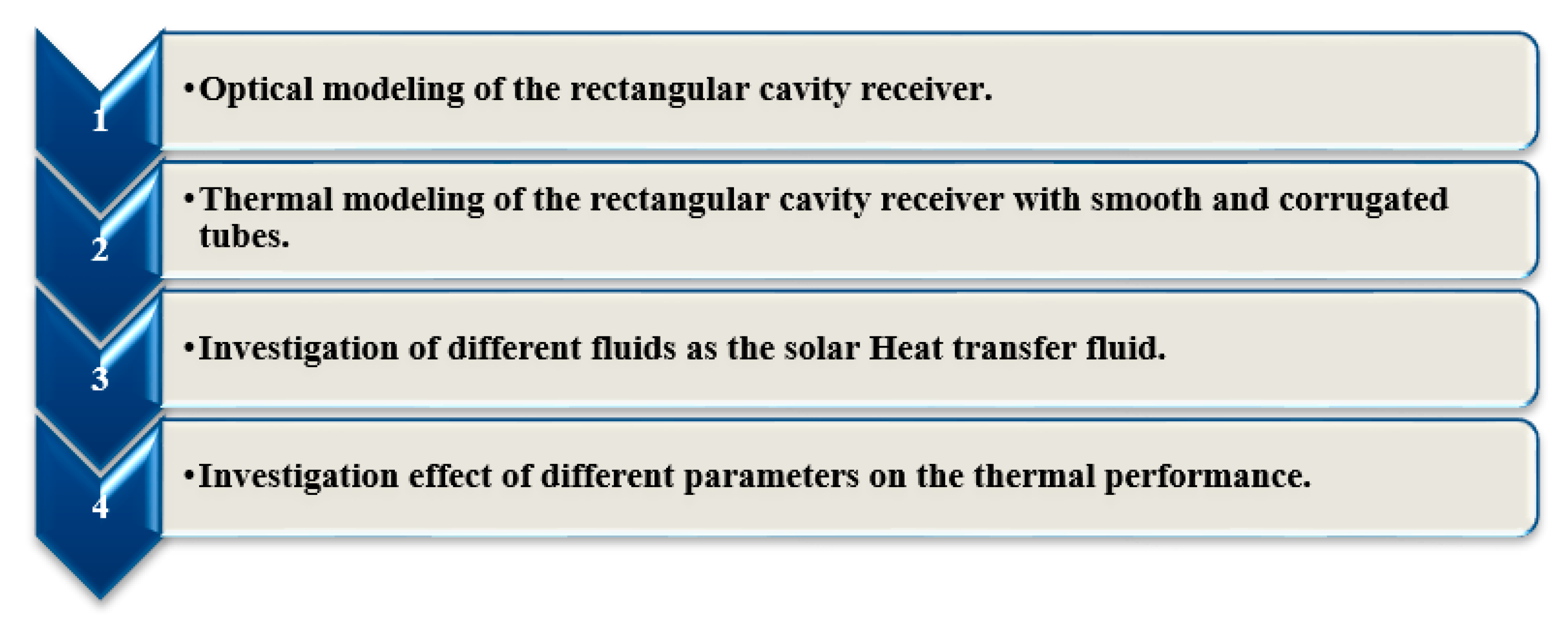
In this research, a solar PTC system with a rectangular cavity receiver was investigated, based on optical and energy aspects. The linear rectangular cavity receiver was investigated using different kinds of cavity tube, including smooth and corrugated tubes. Different solar heat transfer fluids were studied, including air, water, and thermal oil. The solar PTC system with the rectangular cavity receiver was energetically evaluated. The modeling was conducted as follows:
- -
- Optical modeling of the rectangular cavity receiver at optimization dimensions.
- -
- Thermal modeling of the rectangular cavity receiver with smooth and corrugated tubes at optimization dimensions.
- -
- Investigation of different fluids, including air, water, and thermal oil in the solar system.
- -
- Investigation effect of different parameters on the thermal performance of the PTC system, including solar beam irradiation, inlet temperature, and volume flow rate.
A summary of the modeling processes in the current research is presented Figure 1.
2.1. Optical and Thermal Modeling
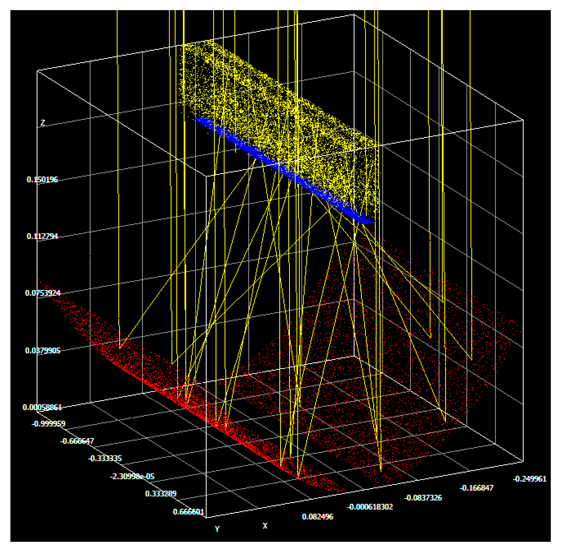
A solar PTC system with a rectangular cavity receiver was optically and thermally investigated. SolTrace software was used, as free and acceptable software developed at the National Renewable Energy Laboratory (NREL), USA, for optical simulation of solar concentrators [16,34]. Figure 2 depicts a view of the optical analysis of the solar PTC system in the SolTrace software. Some constants were assumed during the optical analysis, including: the optical error of 10 mrad, tracking error of 1°, sun-shape of pillbox, number of ray intersections of 10.000, and cavity walls reflectance of 0.15 (see Table 1).
2.2. Thermal Modeling
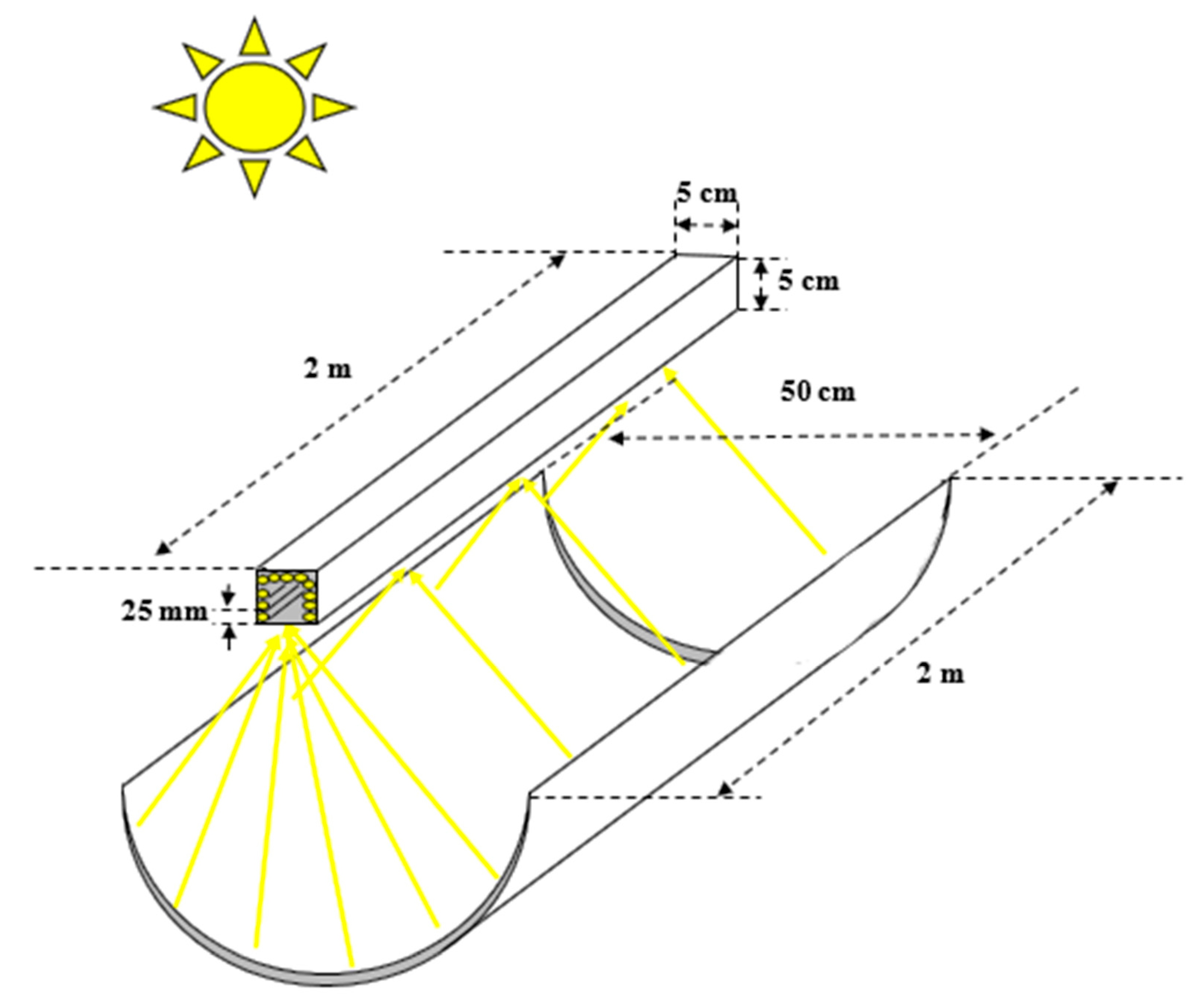
A schematic of the simulated PTC system with rectangular cavity receiver is presented in Figure 3. Different dimensions of the investigated PTC system are presented Figure 3. Solar heat transfer fluid enters the cavity receiver from a side wall and exits from the top wall after circulating the whole length of the cavity tube. The PTC system was thermally modeled based on the energy balance equations that will be presented in detail in the next sections. Different solar heat transfer fluids, including water, air, and thermal oil, were used in this research. Thermal properties of the solar working fluids are presented in Appendix A.
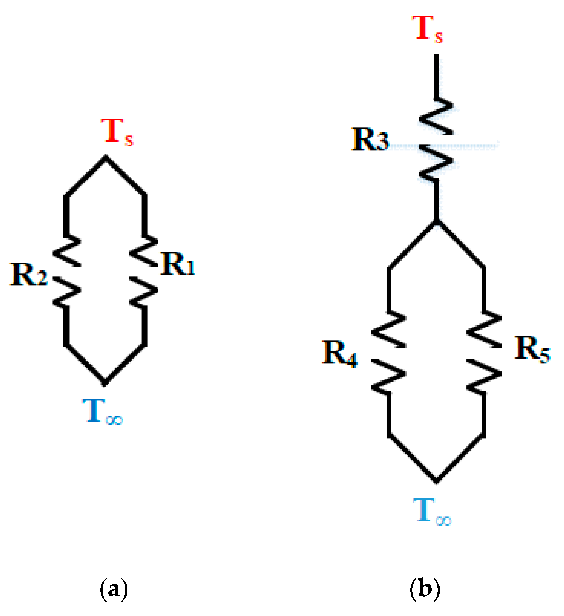
As mentioned, the thermal modeling of the PTC system was conducted based on the energy balance equations using writing codes in Maple software. A schematic of the cavity heat losses based on the thermal resistance method is depicted in Figure 4. The cavity heat losses can be divided as the cavity internal heat losses (Figure 4a) and cavity external heat losses (Figure 4b). In Figure 4a, R1 displays the internal heat losses due to the convection heat losses, and R2 presents the internal heat losses due to the radiation heat losses. On the other side, the cavity walls were covered by insulation except to the cavity aperture. It should be mentioned that R3 in Figure 4b depicts the external heat losses due to the conduction heat losses from the cavity insulation layer. R4 in Figure 4b presents the external heat losses due to the convection heat losses, and R5 shows the external heat losses due to the radiation heat losses. All of the mentioned heat losses will be explained in detail in the next paragraphs.
- Internal Mixed Heat Loss
Thermal heat losses from the linear rectangular cavity receiver due to the convection and radiation heat losses can be estimated by Reference [35]. This study was the closest research for prediction of the internal heat losses of the investigated cavity receiver in the current study. The Nusselt number () for a rectangular cavity receiver due to the convection and radiation heat losses is predicted as follows:
where
Consequently, the internal mixed heat losses can be calculated as:
- External Heat Loss
As mentioned previously, there are external heat losses, including the conduction and mixed external convection heat losses. The conduction heat losses are due to the insulation layer that covered the external sides of the cavity receiver except the cavity aperture. A mineral wool was used as the cavity insulation [36]. The mixed external convection heat losses are due to the heat transfer from the insulation layer to the surrounding environment. The external heat losses of the cavity receiver can be defined based on the thermal resistance method (see Figure 4b) as follows:
- Smooth and Corrugated Tube Simulation
In this research, the rectangular cavity receiver was investigated using smooth and corrugated tube. Effect of both cavity tube kinds on the cavity thermal performance was considered in this section. Internal convection of the heat transfer fluid in the receiver tube can be defined as follows:
where
Using Equations (8) and (9):
Finally, the internal convection of the solar heat transfer fluid in the cavity tube can be calculated as follows:
In this equation, is the internal heat transfer coefficient of the heat transfer fluid in the cavity tube. This coefficient can be calculated as follows:
For the corrugated tube:
For the smooth tube:
- Method to Determine the Optimum Structure of Receiver
The thermal performance of the cavity receiver was determined using solving equations of the cavity received net heat and internal convection of the heat transfer fluid. For improving the accuracy of the calculation, the cavity tube was divided in smaller length, and each length was assumed as an element.
The absorbed net heat by the cavity tube can be calculated as follows:
In this equation, presents the absorbed net heat by element ‘n’, and presents the cavity surface temperature by element ‘n’ as the unknown parameters for each elements. It should be mentioned that is amount of the received solar beam irradiation by each element that was calculated using the SolTrace software. In addition, the internal convection of the solar heat transfer fluid in the cavity tube can be estimated as follows for each element:
Finally, by solving Equations (16) and (17) at the same time using the Newton–Raphson Method [37], and having the same number of the equations and unknown parameters, amounts of the , and for each element are determined. Energy performance of the cavity receiver can be determined using the following equation:
2.3. Validation
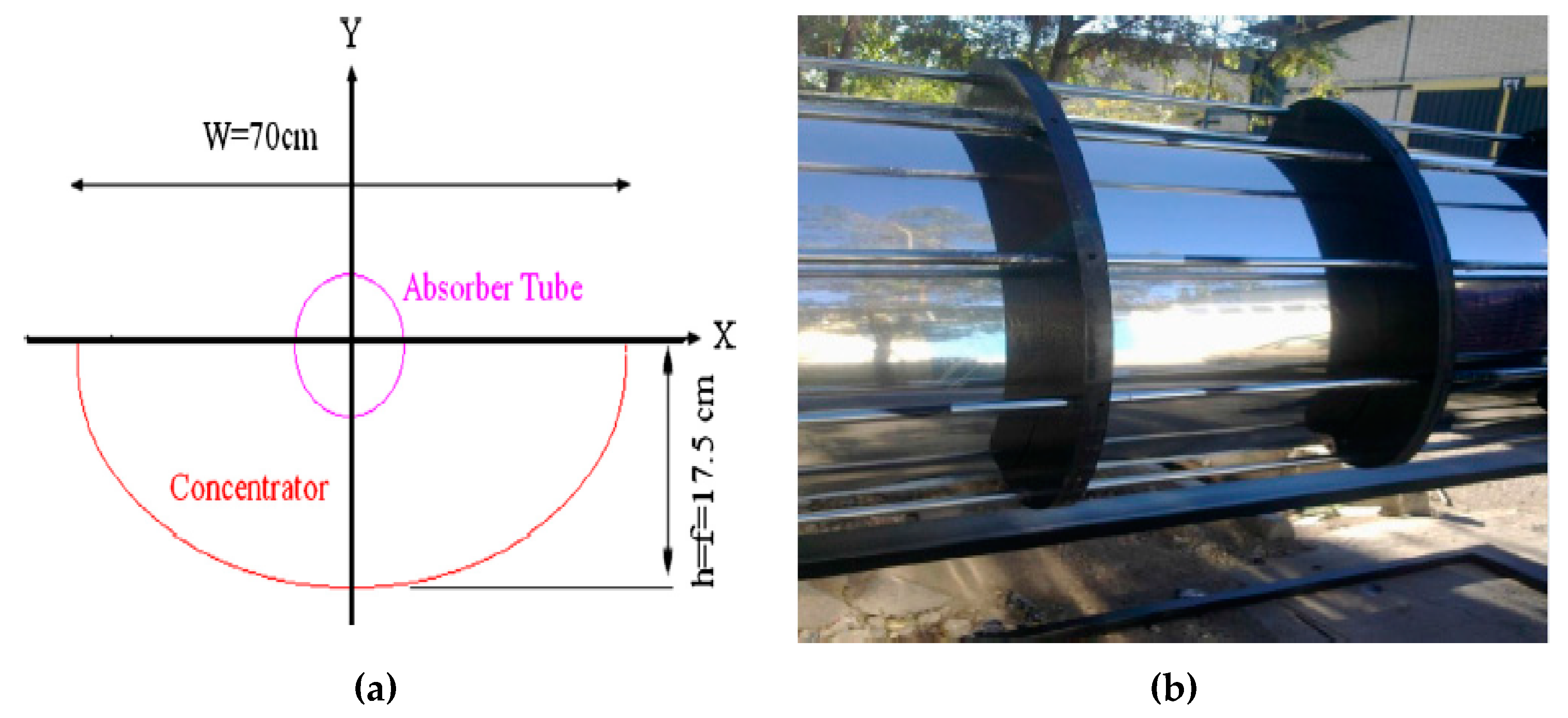
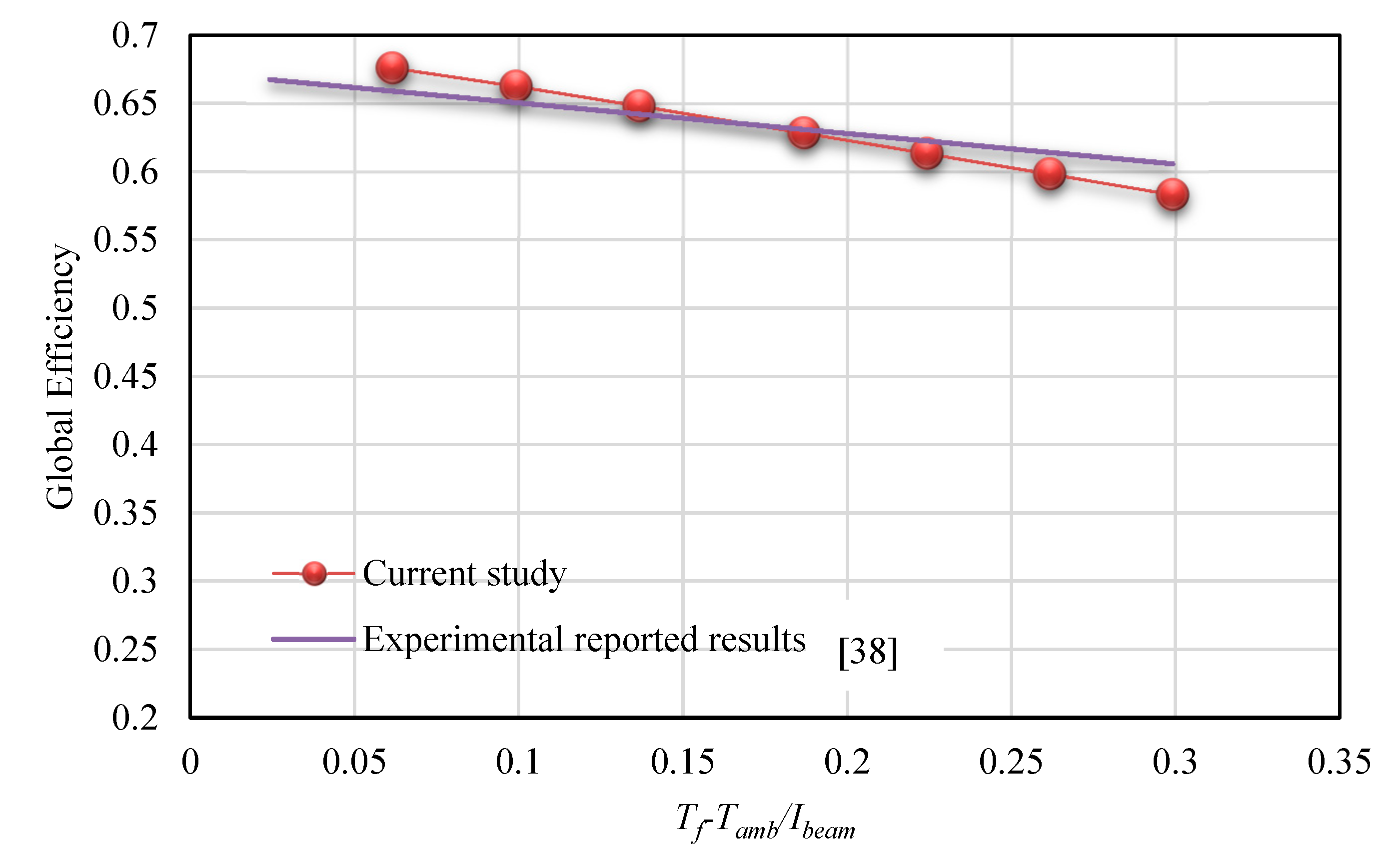
In this research, reported experimental results of a parabolic trough concentrator that was built and tested at Tehran University in Tehran, Iran, was used for validation [38]. The dimensions of the experimental setup are presented in Figure 5. In addition, dimensions of the investigated PTC are presented in Table 2. A PTC system was numerically developed for validation with the same dimensions of the experimental setup. Comparison between the reported experimental results by Reference [31], and the results of the current research are Figure 6. As seen, there is a good agreement between the current numerical results and the measured experimental results by Reference [31].
3. Result and Discussion
In this section, influence of application of different kinds of cavity tube and solar working fluid on thermal performance of the solar PTC system is presented.
3.1. Comparison between Two Kinds of Cavity Tube
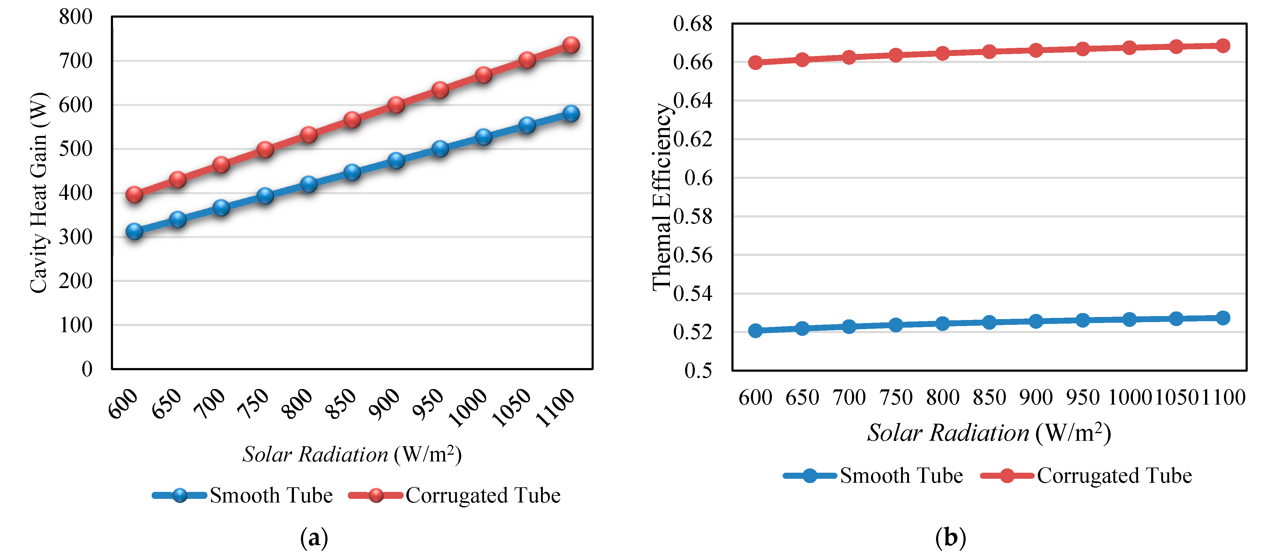
In this part, the influence of different parameters were considered on thermal performance of the solar system, using corrugated, and smooth tube as the cavity tube. Figure 7a,b depict variation of absorbed heat and energy performance of the rectangular cavity receiver with variation of solar beam irradiation in the range of 600 W/m2 to 1100 W/m2 for smooth and corrugated tubes as the cavity tube, respectively. It should be mentioned that thermal oil with inlet temperature of 50 °C and flow rate of 50 mL/s was used as the solar heat transfer fluid. It can be seen that thermal performance of the cavity receiver for both types of the cavity tube improved with increasing solar beam irradiation.
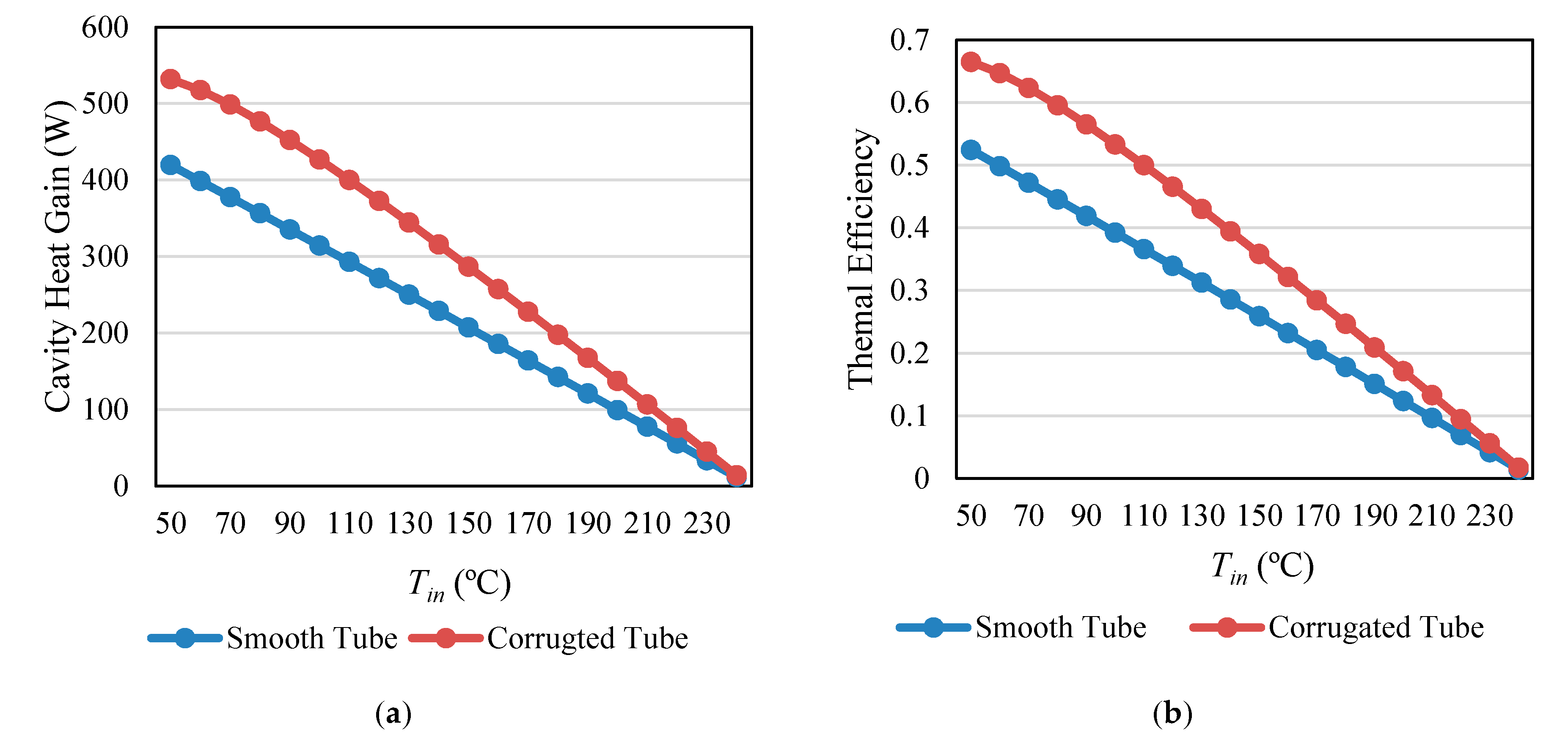
In addition, Figure 8a,b present the variation of the absorbed heat and energy performance of the rectangular cavity receiver under changes of inlet temperature in the range of 50 °C to 230 °C, respectively. The rectangular cavity receiver with two types of the cavity tube, including smooth and corrugated tubes, was investigated. The solar beam irradiation equal to 800 W/m2 and heat transfer fluid as 50 mL/s were assumed in this analysis. It should be mentioned that thermal oil was used as the solar heat transfer fluid. The results showed the absorbed heat and energy performance of the cavity receiver decreased with increasing heat transfer fluid inlet temperature. So, application of the heat transfer fluid is more efficient for achieving higher thermal performance.
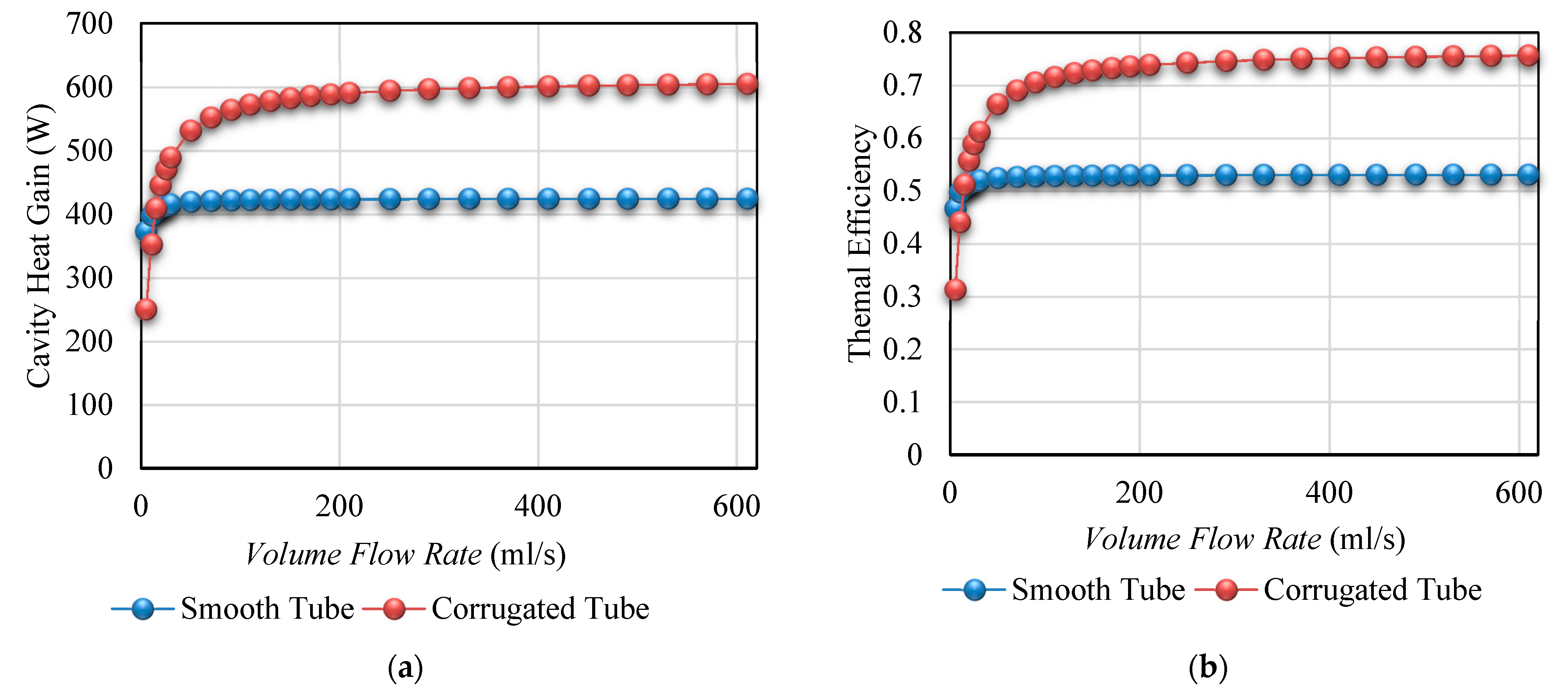
On the other side, variation of absorbed heat and energy performance of the rectangular cavity receiver under variation of flow rate in the range of 0.001 mL/s to 600 mL/s were displayed in Figure 9a,b, respectively. Two types of the cavity tube, including smooth and corrugated tubes, were investigated as the cavity tube. The solar beam irradiation as 800 W/m2 and inlet temperature of heat transfer fluid equal to 50 °C were investigated in this analysis. As concluded, thermal performance of the cavity receiver, including the absorbed heat and thermal performance, increased with increasing heat transfer fluid inlet temperature. So, application of the heat transfer fluid with higher flow rate of the heat transfer fluid is more effective for achieving higher thermal performance.
As seen in Figure 7, Figure 8 and Figure 9, thermal performance of the rectangular cavity was improved using the corrugated tube compared to the smooth tube as the cavity tube. Consequently, the rectangular cavity receiver with corrugated tube showed higher amounts of the absorbed heat and energy performance compared to the smooth tube as the cavity tube. This is because of the higher internal heat transfer of the heat transfer fluid in the corrugated tube compared to the smooth tube. In addition, the trend of the energy performance is similar to the cavity heat. It can be recommended that higher thermal performance can be achieved with corrugated tube as the cavity tube.
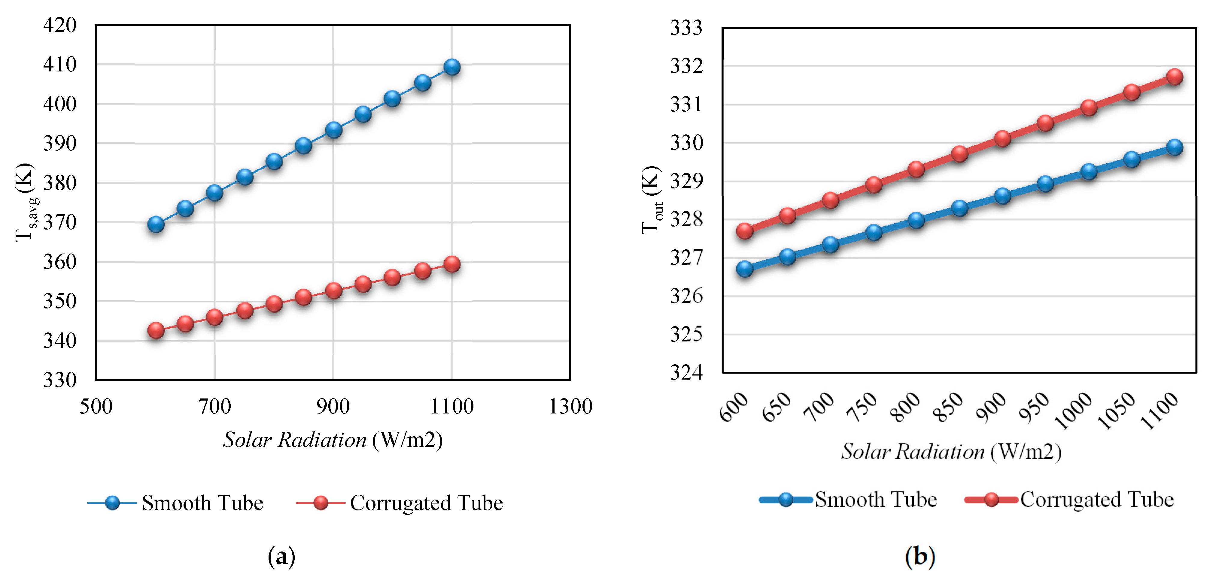
In this part, the influence of different parameters on temperature of cavity walls, and oil were studied, using corrugated, and smooth tube as the cavity tube. Variation of cavity surface temperature, and heat transfer fluid outlet temperature under variation of solar beam irradiation in the range of 600 W/m2 to 1100 W/m2 were presented in Figure 10a,b, respectively. Two types of tube, including smooth and corrugated tubes, were used as the cavity tube. Solar heat transfer fluid was investigated with inlet temperature of 50 °C and flow rate of 50 mL/s. As seen from Figure 10, the cavity surface temperature and outlet temperature of the cavity receiver for both types of the cavity tube enhanced with increasing solar beam irradiation.
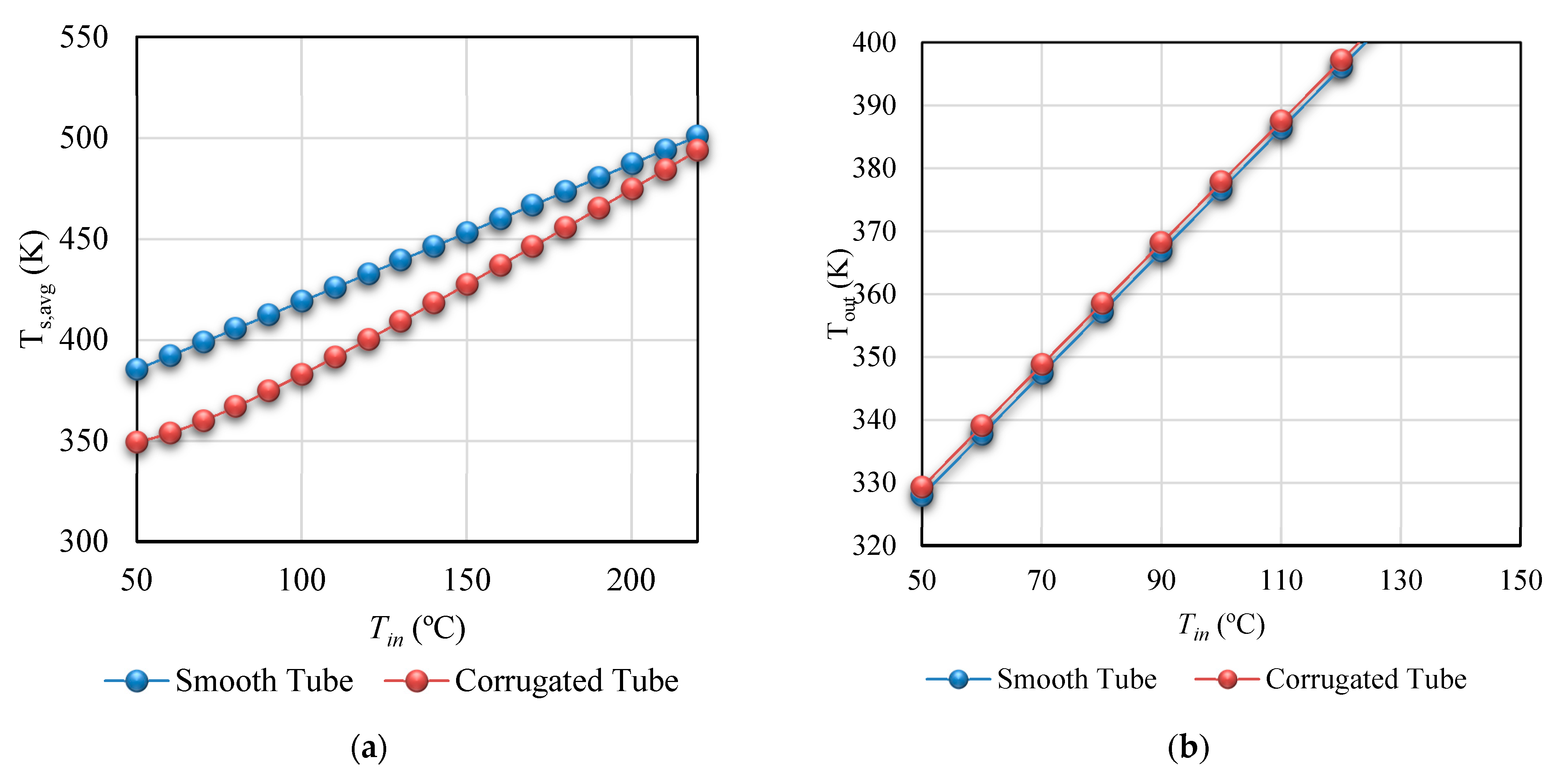
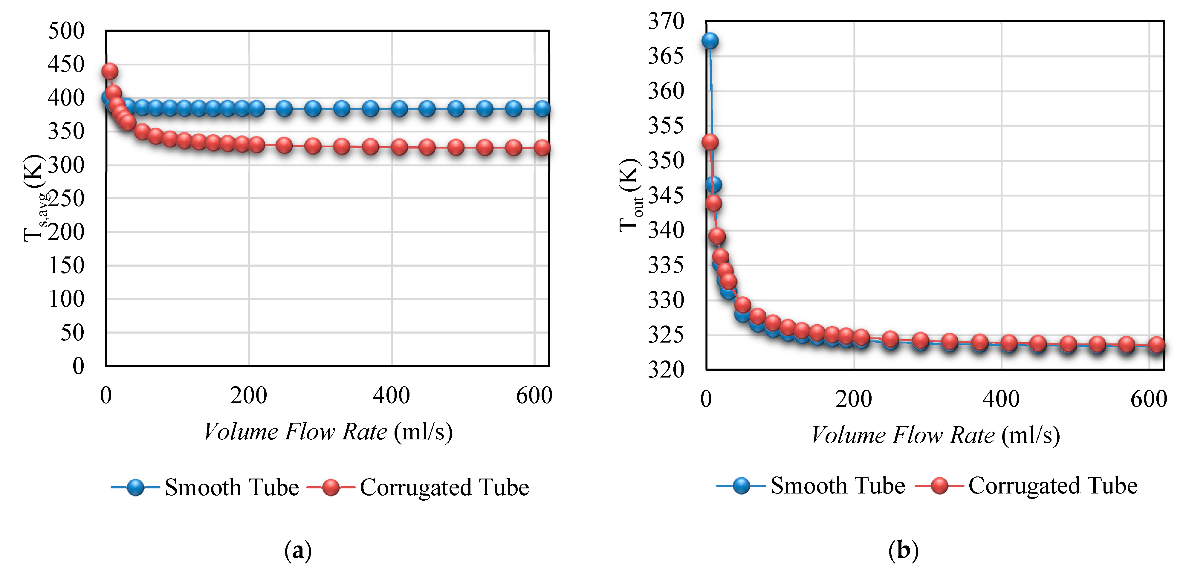
In addition, Figure 11a,b presented the variation temperature of cavity walls and oil under changes of inlet temperature in the range of 50 °C to 230 °C, respectively. These analyses were conducted for rectangular cavity receiver with corrugated, and smooth tube as the cavity tube. It should be mentioned that thermal oil was considered as the solar heat transfer at solar beam irradiation equal to 800 W/m2 and flow rate of 50 mL/s. Results shown in Figure 11 show increasing inlet temperature of the solar heat transfer fluid, as well as increasing cavity wall temperature and oil outlet temperature. On the other side, variation of the temperature of cavity walls and oil under changes of flow rate in the range of 0.001 mL/s to 600 mL/s are presented Figure 12a,b, respectively. The rectangular cavity receiver with smooth and corrugated tubes was investigated as the PTC receiver. It should be mentioned that the solar beam irradiation equal to 800 W/m2 and inlet temperature of heat transfer fluid as 50 °C were assumed in this analysis. As seen in Figure 12, increasing the flow rate of the heat transfer fluid decreased temperature of the cavity walls and oil.
As depicted in Figure 10a, Figure 11a and Figure 12a, the cavity wall temperature with the smooth tube showed higher amounts compared to the corrugated tube as the cavity tube. This is due to the improving internal heat transfer using the corrugated tube. In addition, as seen in the results in Figure 10b, Figure 11b and Figure 12b the outlet temperature of the rectangular cavity receiver with corrugated tube improved. This is caused higher absorbed heat and thermal performance of the rectangular cavity tube with corrugated tube as the cavity tube, as presented in Figure 7, Figure 8 and Figure 9. It can concluded that the rectangular cavity receiver with smooth tube is more appropriate for coupling this system with a Bryton cycle, whereas the rectangular cavity receiver with the corrugated tube is recommended for achieving higher outlet temperature of the heat transfer fluid.
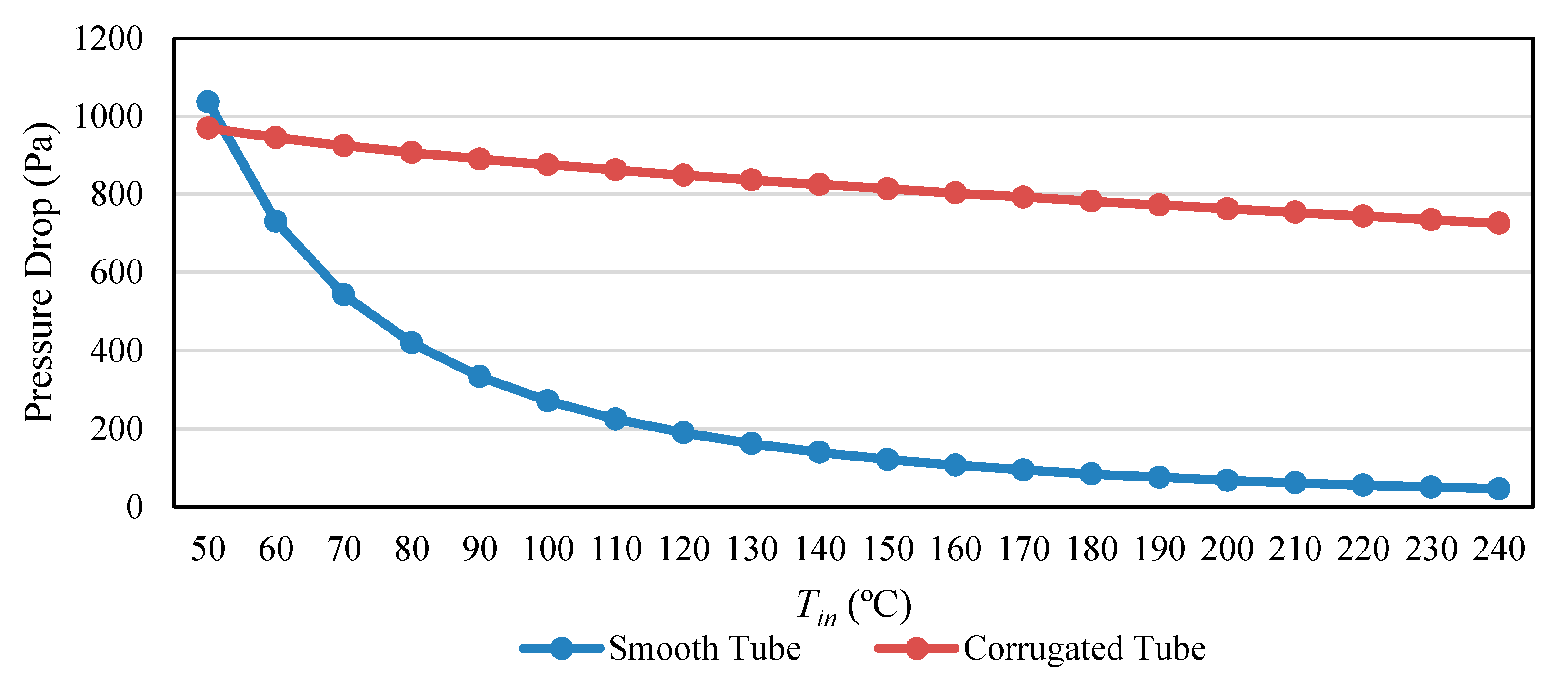
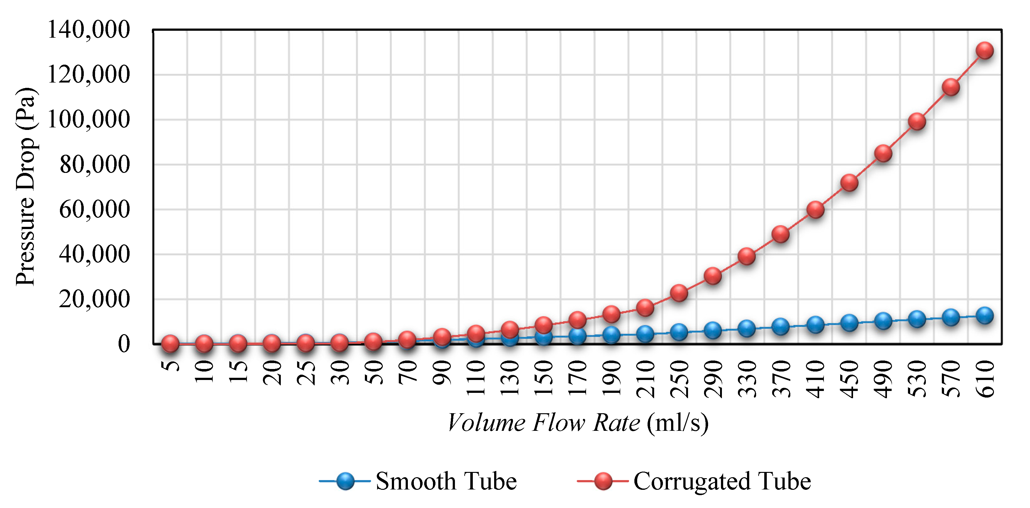
In this part, variation of pressure drop was considered under changes of the inlet temperature and flow rate of solar heat transfer fluid. Figure 13 presents the variation of pressure drop under variation of inlet temperature between 50 °C to 230 °C. The rectangular cavity receiver was investigated for the smooth and corrugated tube as the cavity tube. This analysis was conducted at solar beam irradiation equal to 800 W/m2 and flow rate of 50 mL/s. As seen from Figure 13, the pressure drop of the cavity receiver decreased with increasing oil temperature. In addition, variation of pressure drop under variation of flow rate in the range of 0.001 mL/s to 600 mL/s is presented in Figure 14. The rectangular cavity receiver with two types of the cavity tube, including smooth and corrugated tubes, was studied as the solar PTC receiver. This analysis was conducted under the solar beam irradiation of 800 W/m2. Thermal oil with inlet temperature of 50 °C was used. As Figure 14, the pressure drop increased with increasing volume flow rate of the heat transfer fluid. In Figure 13 and Figure 14, the cavity pressure drop increased with application of the rectangular cavity receiver with the corrugated tube. It can be recommended that lower pressure drop can be achieved with a smooth tube as the cavity tube.
3.2. Comparison of Different Heat Transfer Fluids
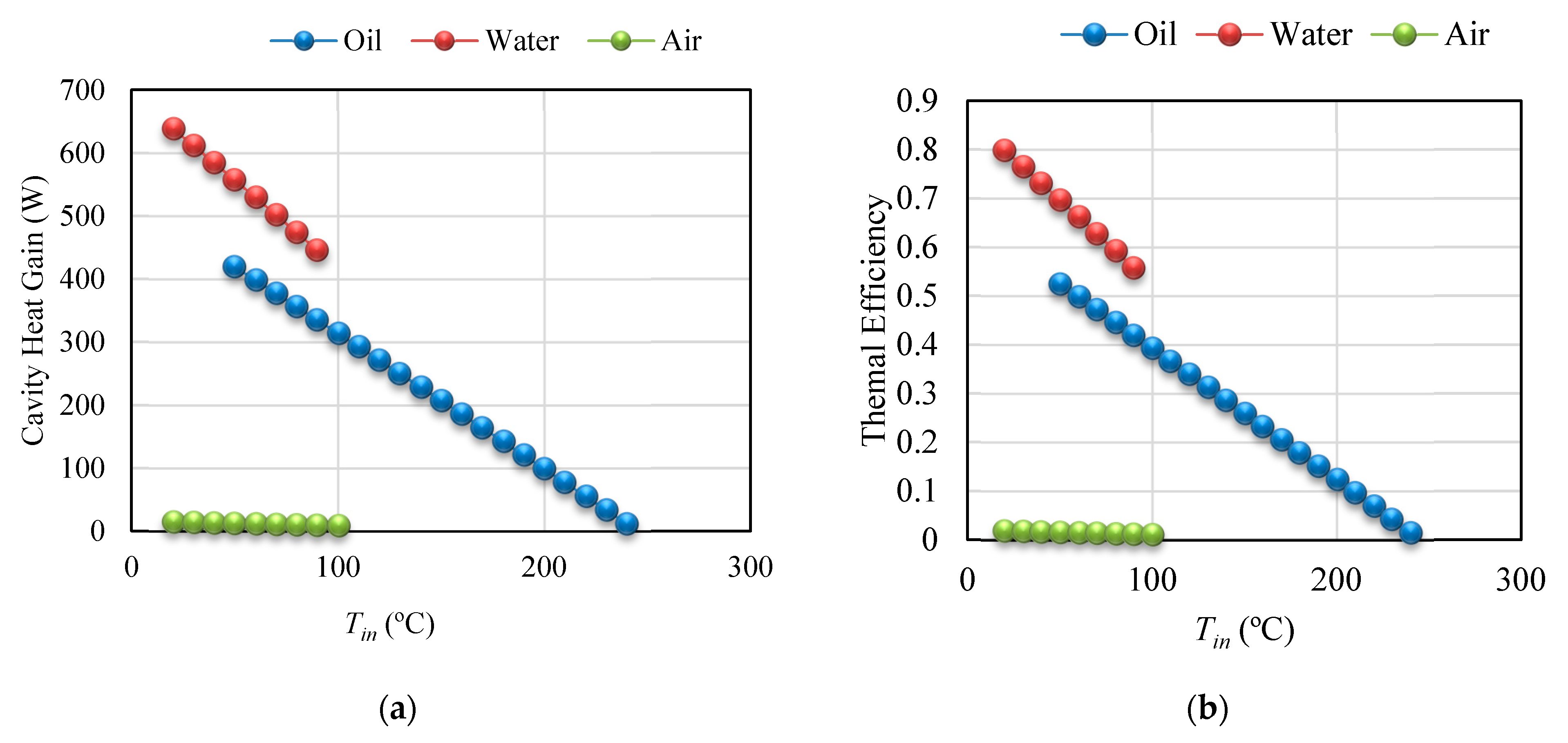
In this part, variation of energy performance under changes of solar beam irradiation, inlet temperature, and flow rate for different heat transfer fluids is considered. Table 3 presents variation of the absorbed heat and energy performance versus different solar beam irradiation in the range of 600 W/m2 to 1100 W/m2. Different fluids, including water, air, and thermal oil, were studied as the solar heat transfer fluid of a rectangular cavity receiver. The rectangular cavity receiver with the smooth tube was considered as the solar PTC receiver. Figure 15a,b depict the variation of absorbed heat and energy performance of the rectangular cavity receiver under changes of inlet temperature in the range of 50 °C to 230 °C, respectively. Three kinds of fluids were considered as the solar heat transfer fluids, including water, air, and thermal oil. The rectangular cavity receiver with a smooth tube was used as the solar PTC receiver. This analysis was conducted at the solar beam irradiation of 800 W/m2 and flow rate of the heat transfer fluids equal to 50 mL/s. Results showed that thermal performance decreased with increasing inlet temperature of three investigated solar heat transfer fluids.
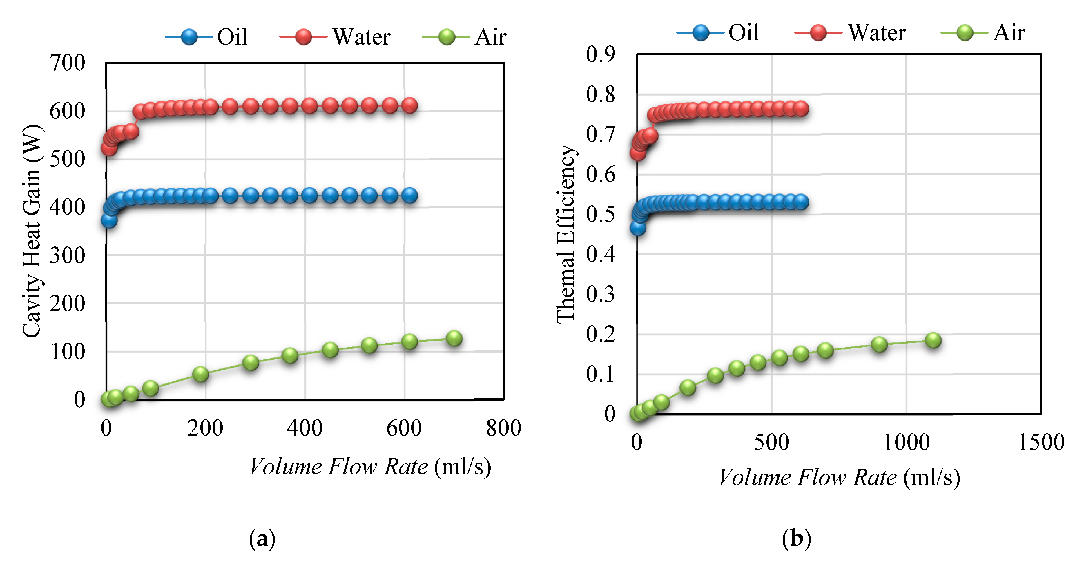
On the other side, Figure 16a,b present the variation of absorbed heat and energy performance of the rectangular cavity receiver under variation of flow rate in the range of 0.001 mL/s to 600 mL/s, respectively. The linear rectangular cavity with smooth tube was applied. Three different fluids, including water, air, and thermal oil, were used as the solar heat transfer fluid. It should be mentioned that the solar beam irradiation equal to 800 W/m2 and inlet temperature of heat transfer fluids equal to 50 °C were assumed in this analysis. As seen, amounts of the absorbed heat and energy performance of the PTC system with the rectangular cavity receiver enhanced with increasing flow rate. As seen from Table 3, Figure 15 and Figure 16, thermal performance of the rectangular cavity was improved using the application of water as the solar heat transfer fluid, which was followed by thermal oil and, finally, air, as the solar heat transfer fluid. As a result, water as the solar heat transfer fluid is appropriate for low-temperature application, whereas the thermal oil as the solar heat transfer fluid is suitable for high-temperature application.
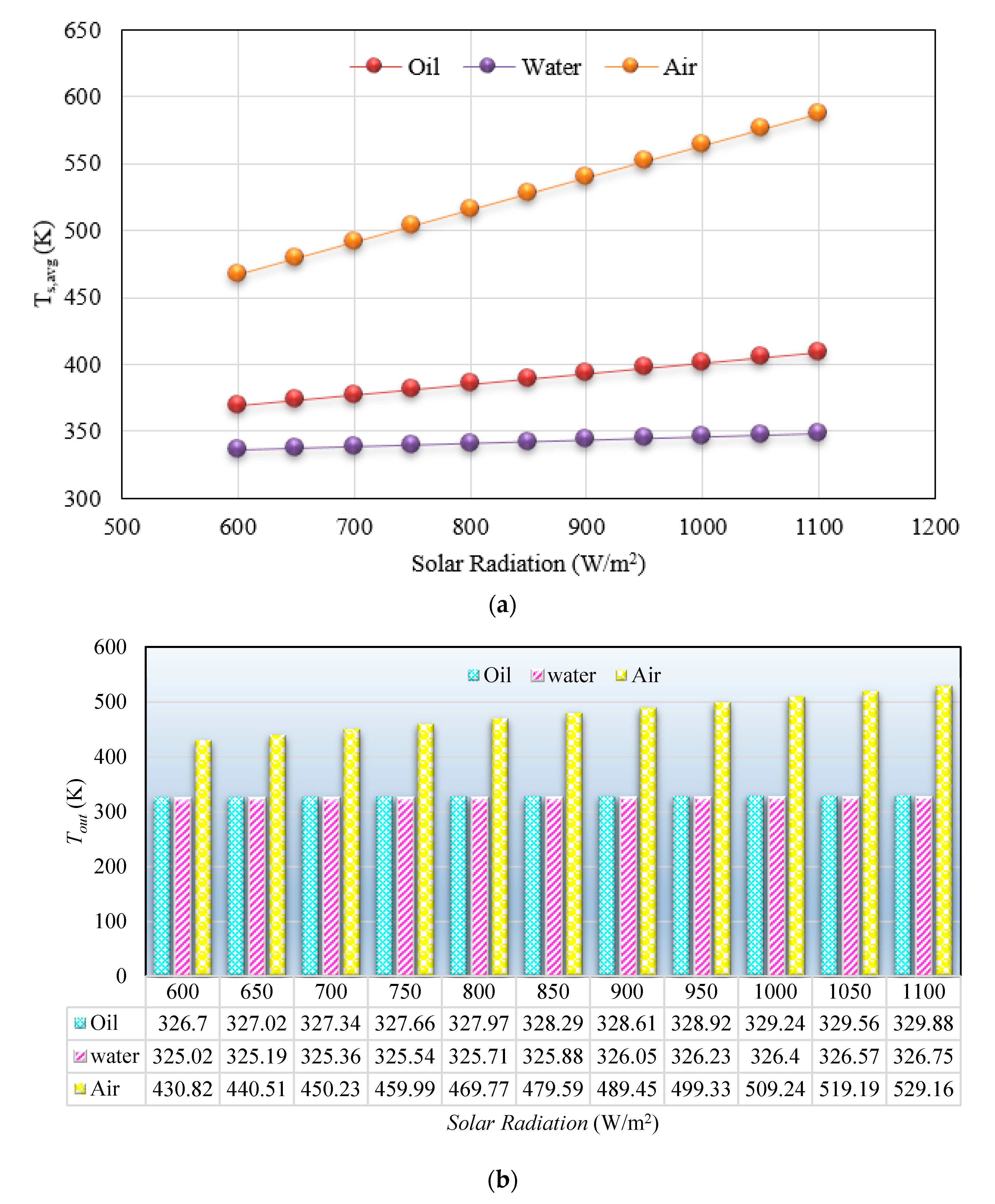
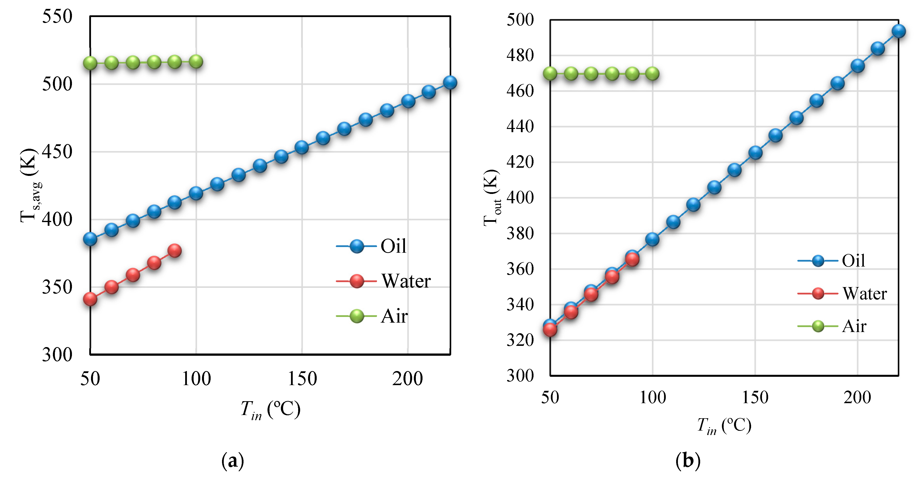
Figure 17a,b depict temperature of cavity walls and heat transfer fluids under variation of solar beam irradiation in the range of 600 W/m2 to 1100 W/m2 for three investigated heat transfer fluids, including water, thermal oil, and air, respectively. The linear rectangular cavity with smooth tube was used. The heat transfer fluids were evaluated under inlet temperature of 50 °C, and flow rate of 50 mL/s. As concluded from Figure 17, the temperature of cavity walls and heat transfer fluids for the three investigated solar heat transfer fluids increased with increasing solar beam irradiation. On the other hand, Figure 18a,b display variation of the cavity surface temperature and heat transfer fluid outlet temperature under changes of inlet temperature in the range of 50 °C to 230 °C for the three investigated heat transfer fluids, including water, thermal oil, and air, respectively. The rectangular cavity receiver with a smooth tube was used. The considered solar heat transfer fluid was studied as flow rate of 50 mL/s, and the solar beam irradiation was investigated equal to 800 W/m2, during these analyses. Results in Figure 18 show higher amounts of the cavity surface temperature and higher outlet temperature of the solar heat transfer fluid, using application of the solar heat transfer fluids with higher inlet temperature for the three investigated solar heat transfer fluids.
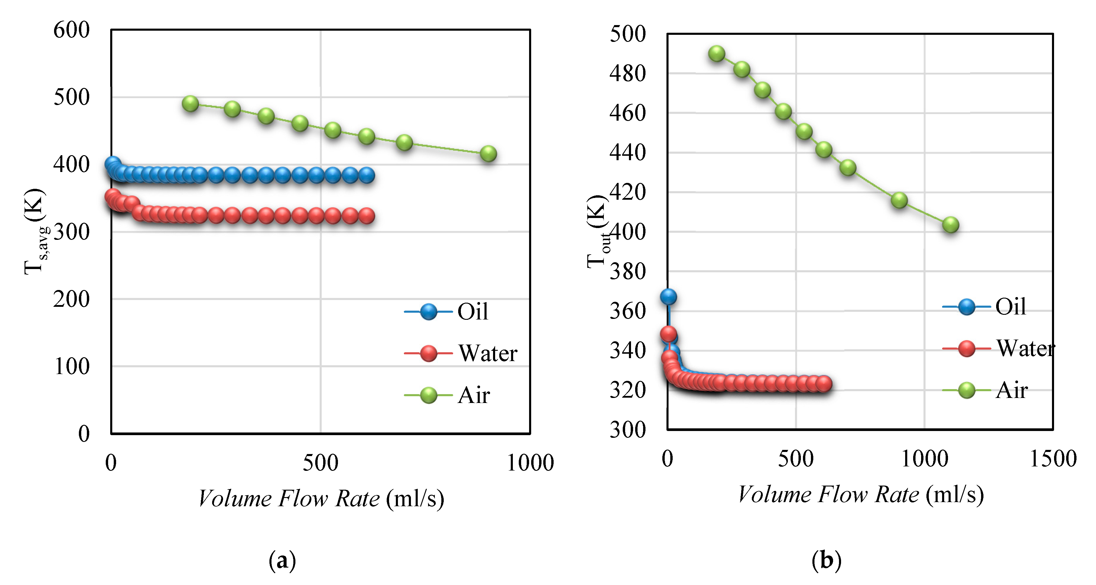
In addition, Figure 19a,b show variation of the temperature of cavity walls and heat transfer fluids under changes of flow rate in the range of 0.001 mL/s to 600 mL/s. The linear rectangular cavity receiver with smooth was investigated. It should be mentioned that the solar beam irradiation equal to 800 W/m2 and inlet temperature of heat transfer fluids as 50 °C were investigated in this analysis. As presented in Figure 19, the temperature of cavity walls and heat transfer fluids decreased with increasing the flow rate of the heat transfer fluid. As concluded from Figure 17, Figure 18 and Figure 19 amounts of the temperature of cavity walls and air as the solar heat transfer fluid presented the highest amount, followed by thermal oil and, finally, water, which showed lowest amounts of the temperature of cavity walls and heat transfer fluids. It could be recommended that the rectangular cavity receiver with air is suitable as the heat source of a Brayton cycle, whereas the rectangular cavity receiver with water as the solar heat transfer fluid can be suggested for achieving the highest thermal performance in low-temperature application. Finally, thermal oil as the solar heat transfer fluid of the rectangular cavity receiver can be recommended as achieving the highest thermal performance in high-temperature application.
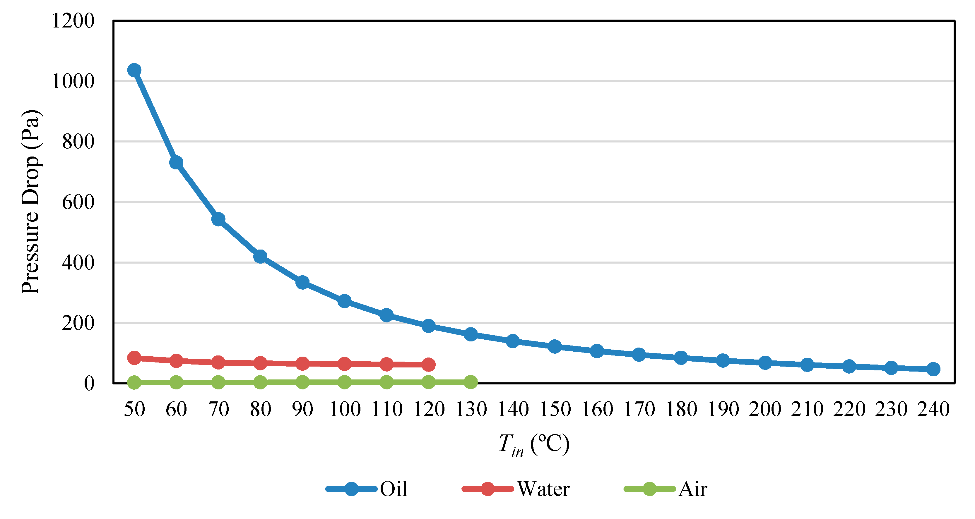
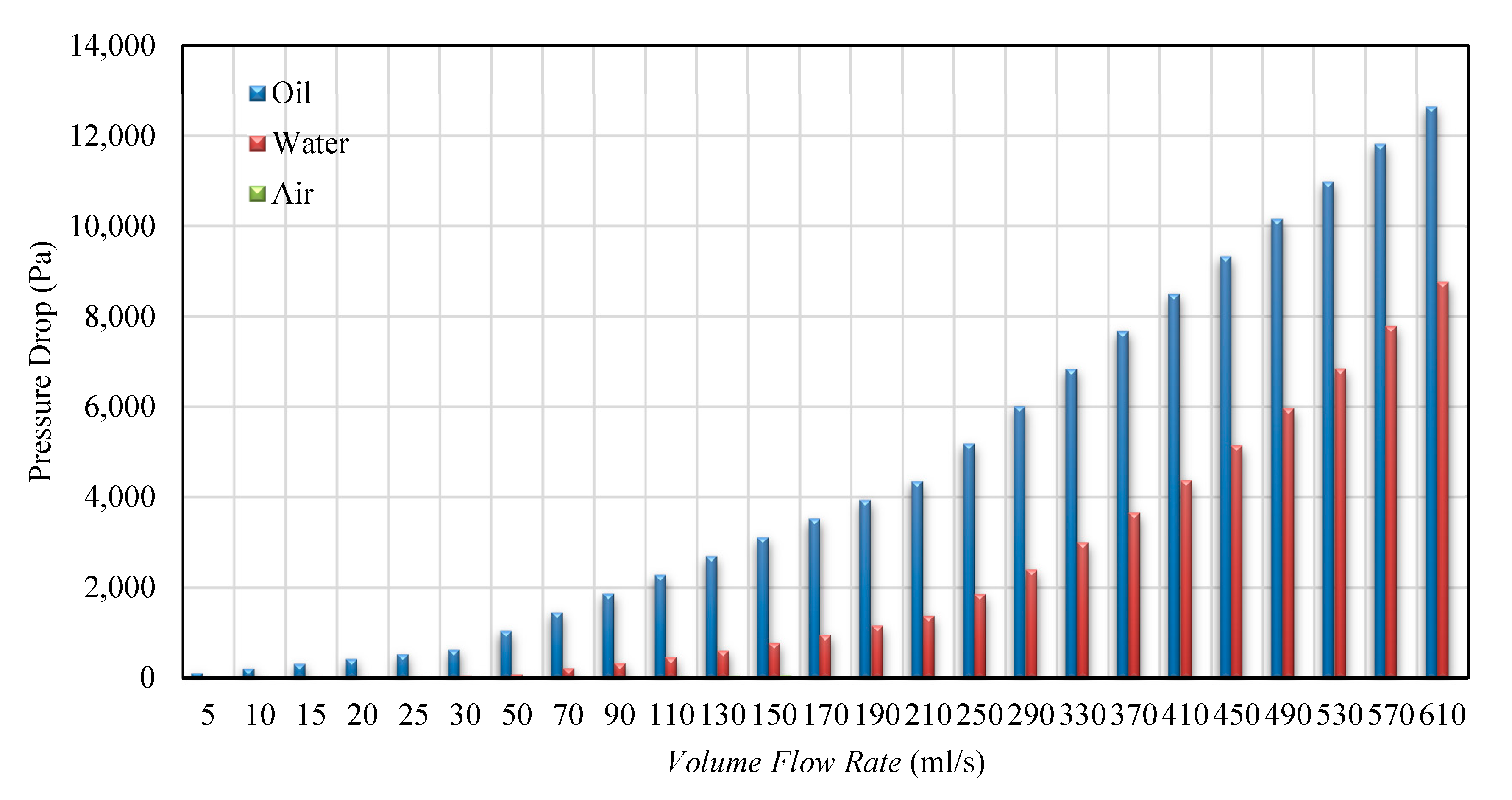
In this section, the variation of pressure drop was considered with the variation of the inlet temperature, and flow rate of solar heat transfer fluids. Variation of pressure drop of the rectangular cavity receiver under variation of inlet temperature between 50 °C to 230 °C is depicted in Figure 20. The rectangular cavity receiver with smooth tube was studied. As mentioned, three different solar heat transfer fluids, including water, thermal oil, and air, were investigated. This study was conducted at solar beam irradiation equal to 800 W/m2, and flow rate of 50 mL/s. As presented in Figure 20, the pressure drop has decreased with increasing inlet temperature of the heat transfer fluid for the three investigated heat transfer fluids. Figure 21 displays variation of pressure drop of the solar system with smooth tube under variation of flow rate in the range of 0.001 mL/s to 600 mL/s for the three investigated solar heat transfer fluids, including thermal oil, water, and air. It should be mentioned that this analysis was conducted for the solar system with inlet temperature of the solar heat transfer fluids equal to 50 °C and the solar beam irradiation of 800 W/m2. As concluded from Figure 21, the pressure drop increased with increasing volume flow rate of the heat transfer fluids for all of the investigated solar heat transfer fluids. As concluded from Figure 20 and Figure 21, the rectangular cavity receiver with thermal oil as the solar heat transfer fluid resulted in the highest pressure drop. On the other side, the rectangular cavity receiver with air as the solar heat transfer fluid showed the lowest pressure drop.
4. Conclusions
In this research, a parabolic trough concentrator with a linear rectangular cavity was investigated. The rectangular cavity receiver was studied using smooth and corrugated cavity tube. Different fluids were evaluated as the solar working of the investigated solar system, including water, thermal oil, and air. Thermal performance of the rectangular cavity receive was considered, using different cavity tube types and application of different solar heat transfer fluids. The results of this study can be summarized as follows:
- -
- It can be seen that absorbed heat and energy performance of the cavity receiver for both types of the cavity tube, using different solar heat transfer fluids, improved with increasing solar beam irradiation, decreasing inlet temperature, and increasing flow rate of the heat transfer fluids. On the other side, the rectangular cavity receiver with corrugated tube showed higher amounts of the absorbed heat and energy performance compared to the smooth tube as the cavity tube. It can be recommended that higher thermal performance can be achieved with corrugated tube as the cavity tube.
- -
- The pressure drop of the cavity receiver using both types of the cavity tube decreased with increasing inlet temperature of the heat transfer fluid, as well as decreasing flow rate of all of the investigated solar heat transfer fluids. On the other side, the cavity pressure drop increased with application of the rectangular cavity receiver with the corrugated tube compared to the smooth tube. It can be recommended that lower pressure drop can be achieved with smooth tube as the cavity tube.
- -
- The thermal performance of the rectangular cavity improved using the application of water as the solar heat transfer fluid, which was followed by thermal oil and, finally, air, as the solar heat transfer fluid. It can be recommended that the rectangular cavity receiver with air, water, and oil is suitable as the heat source of a Brayton cycle, low-temperature application, and high-temperature application, respectively.
Author Contributions
A.R. and R.L. methodology; T.Y. and R.L. formal analysis; A.R. and R.L. writing—original draft preparation; G.N. and R.L. writing—review and editing. All authors have read and agree to the published version of the manuscript.
Funding
Authors are grateful to the Tarbiat Modares University (http://www.modares.ac.ir) for financial supports given under IG/39705 grant for renewable Energies of Modares research group.
Acknowledgments
We thank our colleagues from TMU Renewable Energies Research Institute who provided insight and expertise that greatly assisted this research.
Conflicts of Interest
The authors declare no conflict of interest.
Nomenclature
| A | Area, m2 |
| Aa | Aperture area, m2 |
| PTC aspect ratio, - | |
| a | Nominal cavity aperture, m |
| cp | Specific heat capacity, kJ/kgK |
| c2 | Constant parameter, - |
| dtube | Tube diameter, mm |
| D | Cavity height, m |
| f | Focal distance, cm |
| Fi-j | View factor, - |
| g | Earth’s gravity, m/s2 |
| Heat convection coefficient, W/m2K | |
| Ibeam | Direct beam solar irradiation, W/m2 |
| k | Thermal conductivity, W/mK |
| L | Parabola length, m |
| Mass flow rate, mL/s | |
| m2 | Constant parameter, - |
| Nu | Nusselt number, - |
| Heat rate, W | |
| Absorbed solar energy, W | |
| R | Thermal resistance, Km2/W |
| Re | Reynolds number, - |
| Ra | Rayleigh number, - |
| Pr | Prandtl number, - |
| tins | Insulation thickness, m |
| T | Temperature, °C |
| Tam | Ambient temperature, °C |
| Ts,Ave | Receiver surface average temperature, °C |
| W | Aperture wide, m |
| Vwind | Wind speed, m/s |
Greek Symbols
| Coefficient of thermal expansion (equal to approximately 1/T, for ideal gases) | |
| ΔP | Pressure drop, Pa |
| ε | Emittance, - |
| ηglob | Collector global efficiency, - |
| ηth | Receiver thermal efficiency, - |
| ηopt | Optical efficiency of the receiver, - |
| ηrefl | Concentrator reflectance, - |
| θ | Cavity side angle, ° |
| ν | Kinematic viscosity |
| ρ | Density, kg/m3 |
| σ | Stefan-Boltzmann constant, W/m2K4 |
| φ | Rim angle, ° |
Subscripts and Superscripts
| 0 | at inlet |
| ab | absorbed |
| ap | aperture |
| C | cold |
| cond | conduction |
| conv | convection |
| ext | external |
| f | fluid |
| glob | global |
| H | hot |
| in | inlet |
| int | internal |
| ins | insulation |
| loss | thermal losses |
| n | element number |
| net | useful production |
| out | outlet |
| outer | outer |
| rad | radiation |
| solar | solar energy |
| total | total |
| environmental |
Abbreviations
| PTC | Parabolic trough concentrator |
Appendix A. Thermal Properties of the Heat Transfer Fluid
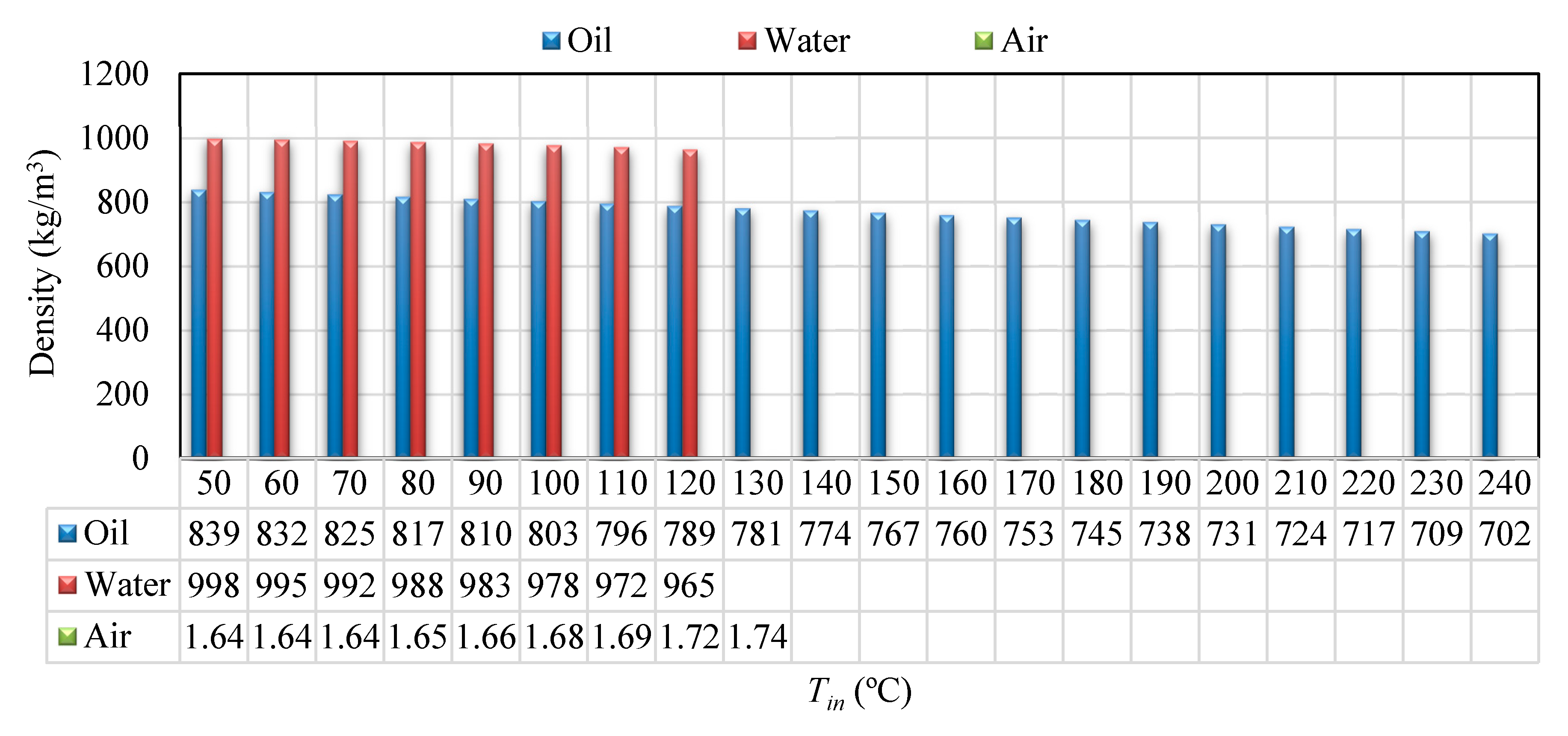
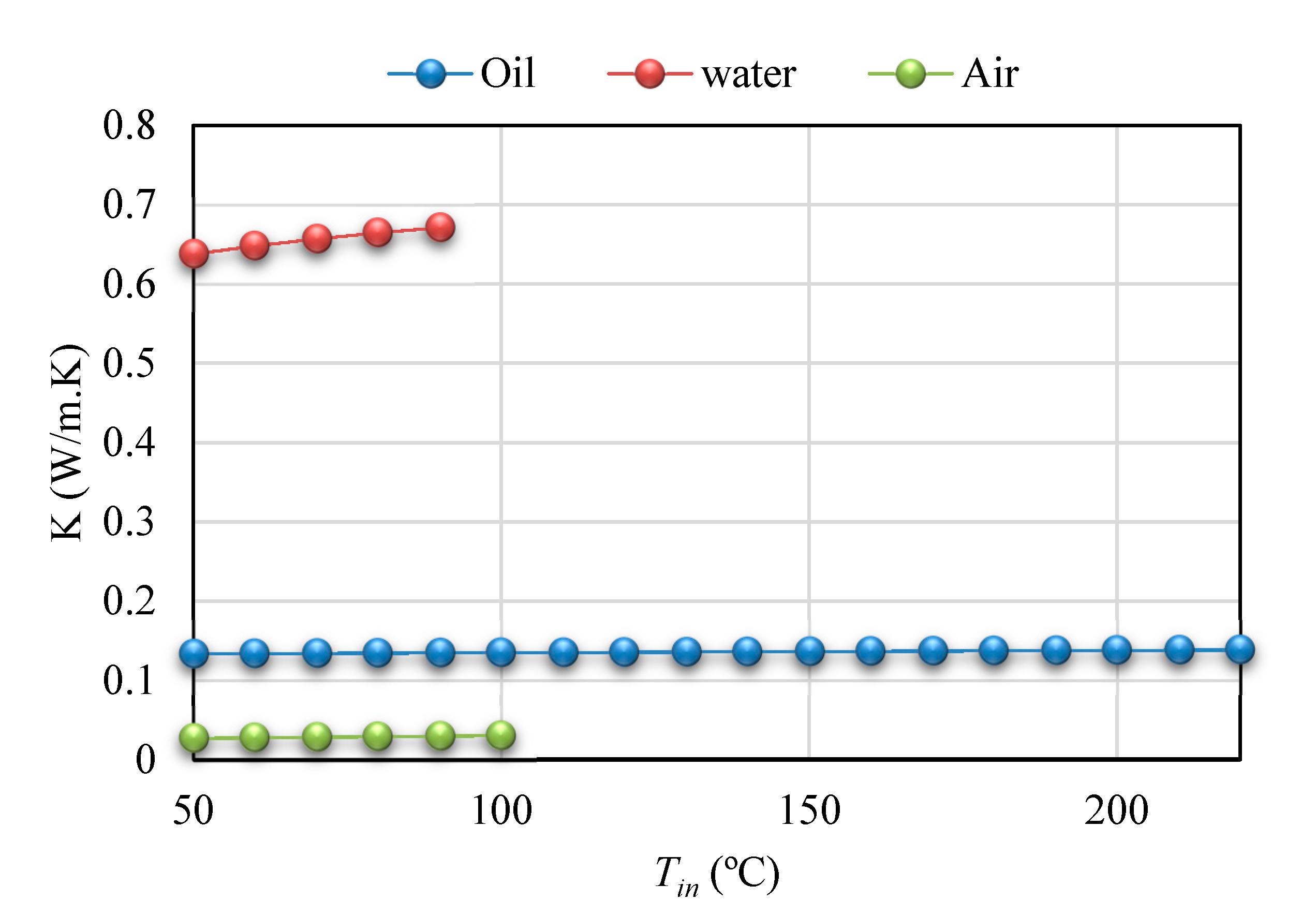
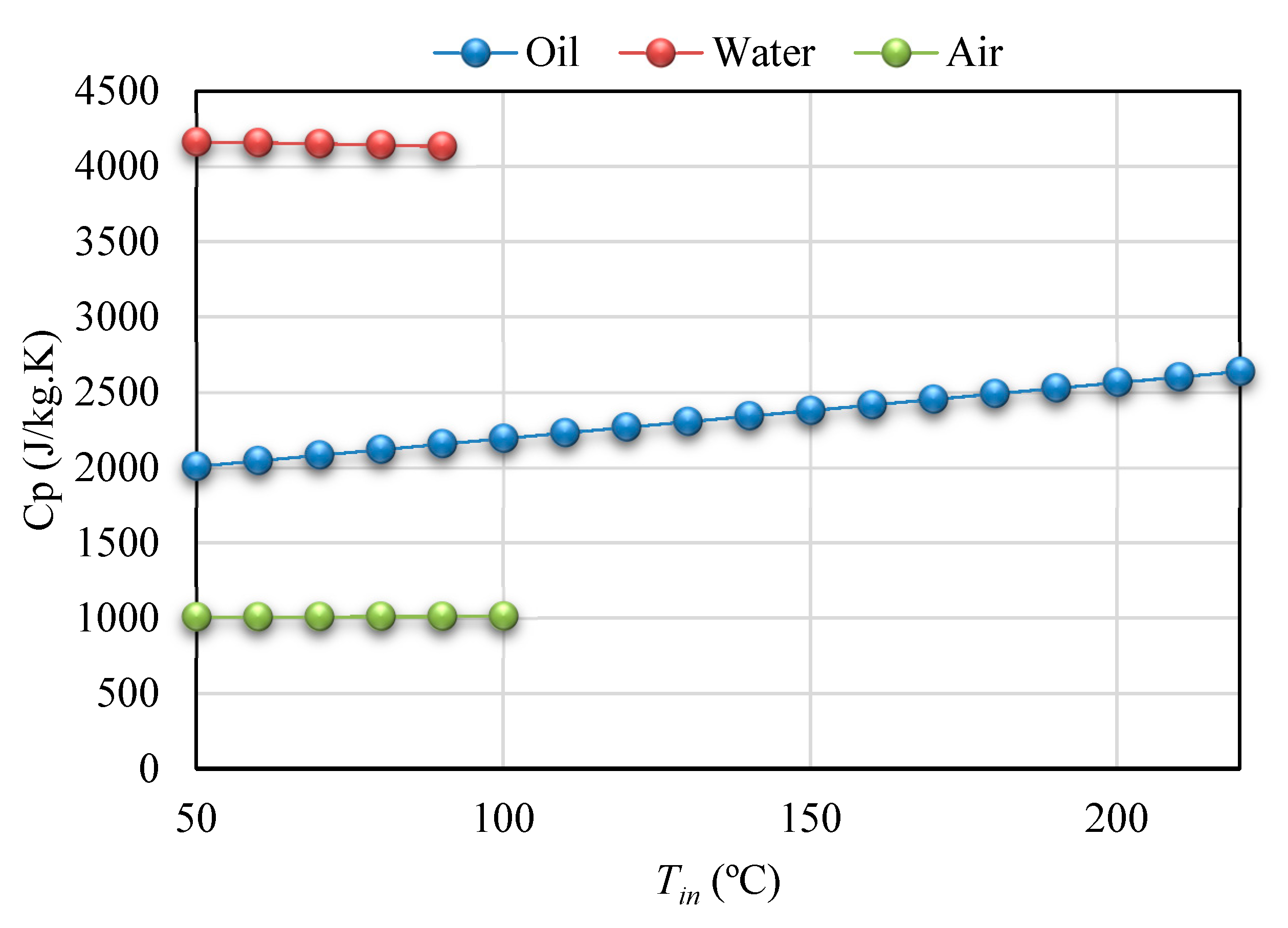
Thermal properties of different heat transfer fluids, including water, air and thermal oil, with variation of the heat transfer fluid temperature are presented in this section. Variation of density, thermal conductivity, and heat capacity of the heat transfer fluid in different temperature are depicted in Figure A1, Figure A2 and Figure A3, respectively [37,39].
Figure A1.
Variation of density versus variation of Heat transfer fluid temperature for water, air, and oil as the heat transfer fluids.
Figure A1.
Variation of density versus variation of Heat transfer fluid temperature for water, air, and oil as the heat transfer fluids.

Figure A2.
Variation of thermal conductivity versus variation of Heat transfer fluid temperature for water, air, and oil as the heat transfer fluids.
Figure A2.
Variation of thermal conductivity versus variation of Heat transfer fluid temperature for water, air, and oil as the heat transfer fluids.

Figure A3.
Variation of heat capacity versus variation of Heat transfer fluid temperature for water, air, and oil as the heat transfer fluids.
Figure A3.
Variation of heat capacity versus variation of Heat transfer fluid temperature for water, air, and oil as the heat transfer fluids.

References
- Bulut, U.; Muratoglu, G. Renewable energy in Turkey: Great potential, low but increasing utilization, and an empirical analysis on renewable energy-growth nexus. Energy Policy 2018, 123, 240–250. [Google Scholar] [CrossRef]
- Guo, S.; Liu, Q.; Sun, J.; Jin, H. A review on the utilization of hybrid renewable energy. Renew. Sustain. Energy Rev. 2018, 91, 1121–1147. [Google Scholar] [CrossRef]
- Phillips, L. Solar energy. In Managing Global Warming: An Interface of Technology and Human Issues; Letcher, T.M., Ed.; Elsevier: Amsterdam, The Netherlands, 2018; pp. 317–332. [Google Scholar]
- Chung, K.-M.; Chen, C.-C.; Chang, K.-C. Effect of diffuse solar radiation on the thermal performance of solar collectors. Case Stud. Therm. Eng. 2018, 12, 759–764. [Google Scholar] [CrossRef]
- Qin, J.; Hu, E.; Nathan, G.J.; Chen, L. Concentrating or non-concentrating solar collectors for solar Aided Power Generation? Energy Convers. Manag. 2017, 152, 281–290. [Google Scholar] [CrossRef]
- Rashid, K.; Mohammadi, K.; Powell, K. Dynamic simulation and techno-economic analysis of a concentrated solar power (CSP) plant hybridized with both thermal energy storage and natural gas. J. Clean. Prod. 2020, 248, 119193. [Google Scholar] [CrossRef]
- Calise, F.; d’Accadia, M.D.; Piacentino, A. A novel solar trigeneration system integrating PVT (photovoltaic/thermal collectors) and SW (seawater) desalination: Dynamic simulation and economic assessment. Energy 2014, 67, 129–148. [Google Scholar] [CrossRef]
- Kincaid, N.; Mungas, G.; Kramer, N.; Wagner, M.; Zhu, G. An optical performance comparison of three concentrating solar power collector designs in linear Fresnel, parabolic trough, and central receiver. Appl. Energy 2018, 231, 1109–1121. [Google Scholar] [CrossRef]
- Rashid, K.; Sheha, M.N.; Powell, K.M. Real-time optimization of a solar-natural gas hybrid power plant to enhance solar power utilization. In Proceedings of the 2018 Annual American Control Conference (ACC), Milwaukee, WI, USA, 27–29 June 2018; pp. 3002–3007. [Google Scholar]
- Nkwetta, D.N.; Smyth, M. The potential applications and advantages of powering solar air-conditioning systems using concentrator augmented solar collectors. Appl. Energy 2012, 89, 380–386. [Google Scholar] [CrossRef]
- Bellos, E.; Tzivanidis, C.; Antonopoulos, K.A. A detailed working fluid investigation for solar parabolic trough collectors. Appl. Therm. Eng. 2017, 114, 374–386. [Google Scholar] [CrossRef]
- Bellos, E.; Tzivanidis, C.; Tsimpoukis, D. Enhancing the performance of parabolic trough collectors using nanofluids and turbulators. Renew. Sustain. Energy Rev. 2018, 91, 358–375. [Google Scholar] [CrossRef]
- Reddy, K.; Satyanarayana, G. Numerical study of porous finned receiver for solar parabolic trough concentrator. Eng. Appl. Comput. Fluid Mech. 2008, 2, 172–184. [Google Scholar] [CrossRef] [Green Version]
- Rashid, K.; Ellingwood, K.; Safdarnejad, S.M.; Powell, K.M. Designing Flexibility into a Hybrid Solar Thermal Power Plant by Real-Time, Adaptive Heat Integration. In Computer Aided Chemical Engineering; Elsevier: Amsterdam, The Netherlands, 2019; Volume 47, pp. 457–462. [Google Scholar]
- Loni, R.; Kasaeian, A.; Asli-Ardeh, E.A.; Ghobadian, B. Optimizing the efficiency of a solar receiver with tubular cylindrical cavity for a solar-powered organic Rankine cycle. Energy 2016, 112, 1259–1272. [Google Scholar] [CrossRef]
- Loni, R.; Kasaeian, A.; Asli-Ardeh, E.A.; Ghobadian, B.; Le Roux, W. Performance study of a solar-assisted organic Rankine cycle using a dish-mounted rectangular-cavity tubular solar receiver. Appl. Therm. Eng. 2016, 108, 1298–1309. [Google Scholar] [CrossRef]
- Yan, J.; Peng, Y.-D.; Cheng, Z.-R. Optimization of a discrete dish concentrator for uniform flux distribution on the cavity receiver of solar concentrator system. Renew. Energy 2018, 129, 431–445. [Google Scholar] [CrossRef]
- Yang, S.; Wang, J.; Lund, P.D.; Jiang, C.; Huang, B. Design and performance evaluation of a high-temperature cavity receiver for a 2-stage dish concentrator. Sol. Energy 2018, 174, 1126–1132. [Google Scholar] [CrossRef]
- Loni, R.; Asli-Ardeh, E.A.; Ghobadian, B.; Bellos, E.; Le Roux, W.G. Numerical comparison of a solar dish concentrator with different cavity receivers and working fluids. J. Clean. Prod. 2018, 198, 1013–1030. [Google Scholar] [CrossRef]
- Uzair, M.; Anderson, T.N.; Nates, R.J. Modeling of convective heat loss from a cavity receiver coupled to a dish concentrator. Sol. Energy 2018, 176, 496–505. [Google Scholar] [CrossRef]
- Yang, S.; Wang, J.; Lund, P.D.; Wang, S.; Jiang, C. Reducing convective heat losses in solar dish cavity receivers through a modified air-curtain system. Sol. Energy 2018, 166, 50–58. [Google Scholar] [CrossRef]
- Soltani, S.; Bonyadi, M.; Avargani, V.M. A novel optical-thermal modeling of a parabolic dish collector with a helically baffled cylindrical cavity receiver. Energy 2018, 168, 88–98. [Google Scholar] [CrossRef]
- Karimi, R.; Gheinani, T.T.; Avargani, V.M. A detailed mathematical model for thermal performance analysis of a cylindrical cavity receiver in a solar parabolic dish collector system. Renew. Energy 2018, 125, 768–782. [Google Scholar] [CrossRef]
- Loni, R.; Asli-Ardeh, E.A.; Ghobadian, B.; Kasaeian, A. Experimental study of carbon nano tube/oil nanofluid in dish concentrator using a cylindrical cavity receiver: Outdoor tests. Energy Convers. Manag. 2018, 165, 593–601. [Google Scholar] [CrossRef] [Green Version]
- Tsekouras, P.; Tzivanidis, C.; Antonopoulos, K. Optical and thermal investigation of a linear Fresnel collector with trapezoidal cavity receiver. Appl. Therm. Eng. 2018, 135, 379–388. [Google Scholar] [CrossRef]
- Roostaee, A.; Ameri, M. Effect of Linear Fresnel Concentrators field key parameters on reflectors configuration, Trapezoidal Cavity Receiver dimension, and heat loss. Renew. Energy 2018, 134, 1447–1464. [Google Scholar] [CrossRef]
- Dabiri, S.; Khodabandeh, E.; Poorfar, A.K.; Mashayekhi, R.; Toghraie, D.; Zade, S.A.A. Parametric investigation of thermal characteristic in trapezoidal cavity receiver for a linear Fresnel solar collector concentrator. Energy 2018, 153, 17–26. [Google Scholar] [CrossRef]
- Lin, M.; Sumathy, K.; Dai, Y.; Zhao, X. Performance investigation on a linear Fresnel lens solar collector using cavity receiver. Sol. Energy 2014, 107, 50–62. [Google Scholar] [CrossRef]
- Reddy, K.; Kumar, K.R. Estimation of convective and radiative heat losses from an inverted trapezoidal cavity receiver of solar linear Fresnel reflector system. Int. J. Therm. Sci. 2014, 80, 48–57. [Google Scholar] [CrossRef]
- Qiu, Y.; He, Y.-L.; Wu, M.; Zheng, Z.-J. A comprehensive model for optical and thermal characterization of a linear Fresnel solar reflector with a trapezoidal cavity receiver. Renew. Energy 2016, 97, 129–144. [Google Scholar] [CrossRef]
- Liang, H.; Zhu, C.; Fan, M.; You, S.; Zhang, H.; Xia, J. Study on the thermal performance of a novel cavity receiver for parabolic trough solar collectors. Appl. Energy 2018, 222, 790–798. [Google Scholar] [CrossRef]
- Liang, H.; Fan, M.; You, S.; Xia, J.; Zhang, H.; Wang, Y. An analysis of the heat loss and overheating protection of a cavity receiver with a novel movable cover for parabolic trough solar collectors. Energy 2018, 158, 719–729. [Google Scholar] [CrossRef]
- Bader, R.; Pedretti, A.; Barbato, M.; Steinfeld, A. An air-based corrugated cavity-receiver for solar parabolic trough concentrators. Appl. Energy 2015, 138, 337–345. [Google Scholar] [CrossRef]
- Le Roux, W.G.; Bello-Ochende, T.; Meyer, J.P. The efficiency of an open-cavity tubular solar receiver for a small-scale solar thermal Brayton cycle. Energy Convers. Manag. 2014, 84, 457–470. [Google Scholar] [CrossRef] [Green Version]
- Natarajan, S.K.; Reddy, K.; Mallick, T.K. Heat loss characteristics of trapezoidal cavity receiver for solar linear concentrating system. Appl. Energy 2012, 93, 523–531. [Google Scholar] [CrossRef]
- Melcome, S.; Khanlari, K.; Mouradian, A.; Ajemian, A.; Ohan, N. Technical Information. Pashme Sang Iran Eng. Design Dep. 2002. Available online: http://pashmesangiran.ir/wp-content/uploads/2020/04/English-Catalogue.pdf (accessed on 24 April 2020).
- Cengel, Y.A.; Ghajar, A.J.; Kanoglu, M. Heat and Mass Transfer: Fundamentals & Applications; McGraw-Hill New York: New York, NY, USA, 2011; Volume 4. [Google Scholar]
- Kasaeian, A.; Daviran, S.; Azarian, R.D.; Rashidi, A. Performance evaluation and nanofluid using capability study of a solar parabolic trough collector. Energy Convers. Manag. 2015, 89, 368–375. [Google Scholar] [CrossRef]
- Baghernejad, A.; Yaghoubi, M. Thermoeconomic methodology for analysis and optimization of a hybrid solar thermal power plant. Int. J. Green Energy 2013, 10, 588–609. [Google Scholar] [CrossRef]
Figure 1.
A summary of the modeling processes in the current research.

Figure 2.
A view of optical analysis of the solar system in the SolTrace software.

Figure 3.
A schematic of the solar Parabolic Trough Concentrator (PTC) with rectangular cavity receiver.
Figure 3.
A schematic of the solar Parabolic Trough Concentrator (PTC) with rectangular cavity receiver.

Figure 4.
A schematic of the cavity heat losses based on thermal resistance method: (a) internal heat losses and (b) external heat losses.
Figure 4.
A schematic of the cavity heat losses based on thermal resistance method: (a) internal heat losses and (b) external heat losses.

Figure 5.
Investigated PTC system (a) dimensions of designed parabola and (b) built PTC system [38].
Figure 5.
Investigated PTC system (a) dimensions of designed parabola and (b) built PTC system [38].

Figure 6.
Comparison between the reported experimental results by Reference [38] and the results of the current research.
Figure 6.
Comparison between the reported experimental results by Reference [38] and the results of the current research.

Figure 7.
Influence of solar radiation on thermal performance of the system including: (a) Variation of absorbed heat and (b) Variation of energy performance with variation of solar beam irradiation for smooth and corrugated tube as the cavity tube.
Figure 7.
Influence of solar radiation on thermal performance of the system including: (a) Variation of absorbed heat and (b) Variation of energy performance with variation of solar beam irradiation for smooth and corrugated tube as the cavity tube.

Figure 8.
Influence of inlet temperature on thermal performance of the system including: (a) variation of absorbed heat and (b) variation of energy performance with variation inlet temperature for smooth and corrugated tube as the cavity tube.
Figure 8.
Influence of inlet temperature on thermal performance of the system including: (a) variation of absorbed heat and (b) variation of energy performance with variation inlet temperature for smooth and corrugated tube as the cavity tube.

Figure 9.
Influence of flow rate of solar working fluid on thermal performance of the system including variation of: (a) absorbed heat and (b) energy performance with variation volume flow rate for smooth and corrugated tube as the cavity tube.
Figure 9.
Influence of flow rate of solar working fluid on thermal performance of the system including variation of: (a) absorbed heat and (b) energy performance with variation volume flow rate for smooth and corrugated tube as the cavity tube.

Figure 10.
Influence of solar radiation on temperature of the cavity and working fluid including variation of: (a) cavity surface temperature and (b) outlet temperature with variation solar beam irradiation for smooth and corrugated tube as the cavity tube.
Figure 10.
Influence of solar radiation on temperature of the cavity and working fluid including variation of: (a) cavity surface temperature and (b) outlet temperature with variation solar beam irradiation for smooth and corrugated tube as the cavity tube.

Figure 11.
Influence of inlet temperature on temperature of the cavity and working fluid including variation of: (a) cavity surface temperature and (b) outlet temperature with variation inlet temperature for smooth and corrugated tube as the cavity tube.
Figure 11.
Influence of inlet temperature on temperature of the cavity and working fluid including variation of: (a) cavity surface temperature and (b) outlet temperature with variation inlet temperature for smooth and corrugated tube as the cavity tube.

Figure 12.
Influence of flow rate on temperature of the cavity and working fluid including variation of: (a) cavity surface temperature and (b) outlet temperature with variation volume flow rate for smooth and corrugated tube as the cavity tube.
Figure 12.
Influence of flow rate on temperature of the cavity and working fluid including variation of: (a) cavity surface temperature and (b) outlet temperature with variation volume flow rate for smooth and corrugated tube as the cavity tube.

Figure 13.
Variation of pressure drop with variation inlet temperature for smooth and corrugated tube as the cavity tube.
Figure 13.
Variation of pressure drop with variation inlet temperature for smooth and corrugated tube as the cavity tube.

Figure 14.
Variation of pressure drop with variation volume flow rate for smooth and corrugated tube as the cavity tube.
Figure 14.
Variation of pressure drop with variation volume flow rate for smooth and corrugated tube as the cavity tube.

Figure 15.
Influence of inlet temperature on thermal performance of the solar system including variation of: (a) absorbed heat and (b) energy performance versus variation of inlet temperature for different solar heat transfer fluids.
Figure 15.
Influence of inlet temperature on thermal performance of the solar system including variation of: (a) absorbed heat and (b) energy performance versus variation of inlet temperature for different solar heat transfer fluids.

Figure 16.
Influence of flow rate on thermal performance of the solar system including variation of: (a) absorbed heat and (b) energy performance with variation volume flow rate for different solar heat transfer fluids.
Figure 16.
Influence of flow rate on thermal performance of the solar system including variation of: (a) absorbed heat and (b) energy performance with variation volume flow rate for different solar heat transfer fluids.

Figure 17.
Influence of solar radiation on temperature of cavity and working fluid including variation of: (a) cavity surface temperature and (b) outlet temperature versus solar beam irradiation for different solar heat transfer fluids.
Figure 17.
Influence of solar radiation on temperature of cavity and working fluid including variation of: (a) cavity surface temperature and (b) outlet temperature versus solar beam irradiation for different solar heat transfer fluids.

Figure 18.
Influence of inlet temperature on temperature of cavity and working fluid including variation of: (a) cavity surface temperature and (b) outlet temperature versus variation of inlet temperature for different solar heat transfer fluids.
Figure 18.
Influence of inlet temperature on temperature of cavity and working fluid including variation of: (a) cavity surface temperature and (b) outlet temperature versus variation of inlet temperature for different solar heat transfer fluids.

Figure 19.
Influence of flow rate on temperature of cavity and working fluid including variation of: (a) cavity surface temperature and (b) outlet temperature with variation volume flow rate for different solar heat transfer fluids.
Figure 19.
Influence of flow rate on temperature of cavity and working fluid including variation of: (a) cavity surface temperature and (b) outlet temperature with variation volume flow rate for different solar heat transfer fluids.

Figure 20.
Variation of pressure drop with variation inlet temperature for different solar heat transfer fluids.
Figure 20.
Variation of pressure drop with variation inlet temperature for different solar heat transfer fluids.

Figure 21.
Variation of pressure drop with variation volume flow rate for different solar heat transfer fluids.
Figure 21.
Variation of pressure drop with variation volume flow rate for different solar heat transfer fluids.


Table 1.
The SolTrace modeling’s assumed constants.
| The optical error1 | 0–35 mrad |
| The tracking error2 | 1° |
| The sun-shape | pillbox |
| The half-angle width | 4.65 mrad |
| Number of ray intersections | 10,000 |
| The reflectance of the cavity walls (black cobalt coating) | 15% |
1. Optical error = (4(slope error2) + (secularity error2)) 1/2; 2. Error between a movement of mirror surface and receiver.
Table 2.
Dimensions of steel mirror reflector.
| Description | Dimension |
|---|---|
| Parabola length (L) | 2 m |
| Parabola aperture (w) | 70 cm |
| Focal distance (f) | 17.5 cm |
| Aperture area (Aa) | 1.4 m2 |
| Rim angle () | 90° |
| Thickness (mean value) | 0.8 mm |
Table 3.
Variation of the absorbed heat and energy performance versus different solar beam irradiation for different heat transfer fluids.
Table 3.
Variation of the absorbed heat and energy performance versus different solar beam irradiation for different heat transfer fluids.
| Ibeam (W/m2) | 600 | 650 | 700 | 750 | 800 | 850 | 900 | 950 | 1000 | 1050 | 1100 |
|---|---|---|---|---|---|---|---|---|---|---|---|
| Absorbed Heat (W) | |||||||||||
| Oil | 312.43 | 339.21 | 365.99 | 392.76 | 419.53 | 446.29 | 473.06 | 499.82 | 526.57 | 553.33 | 580.07 |
| Water | 414.90 | 450.48 | 486.07 | 521.65 | 557.24 | 592.82 | 628.41 | 663.99 | 699.57 | 735.15 | 770.74 |
| Air | 8.99 | 9.79 | 10.60 | 11.42 | 12.23 | 13.05 | 13.87 | 14.69 | 15.52 | 16.35 | 17.18 |
| Energy Performance | |||||||||||
| Oil | 0.521 | 0.522 | 0.523 | 0.524 | 0.524 | 0.525 | 0.526 | 0.526 | 0.527 | 0.527 | 0.527 |
| Water | 0.691 | 0.693 | 0.694 | 0.696 | 0.697 | 0.697 | 0.698 | 0.699 | 0.700 | 0.700 | 0.701 |
| Air | 0.015 | 0.015 | 0.015 | 0.015 | 0.015 | 0.015 | 0.015 | 0.015 | 0.016 | 0.016 | 0.016 |
© 2020 by the authors. Licensee MDPI, Basel, Switzerland. This article is an open access article distributed under the terms and conditions of the Creative Commons Attribution (CC BY) license (http://creativecommons.org/licenses/by/4.0/).
Share and Cite
MDPI and ACS Style
Rafiei, A.; Loni, R.; Najafi, G.; Yusaf, T. Study of PTC System with Rectangular Cavity Receiver with Different Receiver Tube Shapes Using Oil, Water and Air. Energies 2020, 13, 2114. https://0-doi-org.brum.beds.ac.uk/10.3390/en13082114
AMA Style
Rafiei A, Loni R, Najafi G, Yusaf T. Study of PTC System with Rectangular Cavity Receiver with Different Receiver Tube Shapes Using Oil, Water and Air. Energies. 2020; 13(8):2114. https://0-doi-org.brum.beds.ac.uk/10.3390/en13082114
Chicago/Turabian StyleRafiei, Alireza, Reyhaneh Loni, Gholamhassan Najafi, and Talal Yusaf. 2020. "Study of PTC System with Rectangular Cavity Receiver with Different Receiver Tube Shapes Using Oil, Water and Air" Energies 13, no. 8: 2114. https://0-doi-org.brum.beds.ac.uk/10.3390/en13082114
Note that from the first issue of 2016, this journal uses article numbers instead of page numbers. See further details here.