Advanced Control of a Compensator Motor Driving a Variable Speed Diesel Generator with Rotating Stator


1
Wind Energy Research Laboratory (WERL), Université du Québec à Rimouski, Rimouski, QC G5L 3A1, Canada
2
Department of Computer Science and Engineering, Université du Québec à Rimouski, Rimouski, QC G5L 3A1, Canada
3
Electrical Engineering Department, Ecole de Technologie Superieure, Montréal, QC H3C 1K3, Canada
*
Author to whom correspondence should be addressed.
Energies 2020, 13(9), 2224; https://0-doi-org.brum.beds.ac.uk/10.3390/en13092224
Submission received: 4 April 2020
/
Revised: 19 April 2020
/
Accepted: 22 April 2020
/
Published: 2 May 2020
Abstract
:Variable speed generators can improve overall genset performance by allowing the diesel engine to reduce its speed at lower loads. In this project, a variable speed diesel generator (VSDG) uses a rotating stator driven by a compensator motor. At lower loads, the stator turns in the opposite direction of the rotor, a process that can be used for purposes like maintaining a fixed relative speed between the two components of a generator. This allows the diesel engine to turn at a lower speed (same as the rotor) and to increase its efficiency. The present research addresses the control of the compensator motor driving the generator’s stator using a variable-frequency drive that adapts the speed to its optimal value according to the load. The performance of the proposed control strategy was tested using a Freescale microcontroller card programmed in C-code to determine the appropriate voltage for the variable-frequency drive. The control algorithm uses a real-time application implemented on an FDRM-KL25Z signal processor board. The control performance of a 2 kW asynchronous motor (LabVolt EMS 8503-00/208 V/3 ϕ/60(50) Hz) was demonstrated experimentally at different operating conditions.
1. Introduction
Nowadays, several electric production applications such as hybrid standalone or grid-connected applications are still using diesel generators (DGs). Despite the huge growth of renewable energy contributions in electric production, DG performance optimization is critical due to its important role in electric energy production. This research focuses on the optimization of a variable speed diesel generator (VSDG) based on a new rotating stator technology for an electric generator. The stator rotation and synchronization with the rotor is controlled by a compensator variable speed AC motor. This section addresses the state-of-the-art of existing technologies related to the project.
1.1. Variable Speed Diesel Generator
Conventional diesel generators (DGs) generally operate at fixed speeds, 1800 or 1500 rpm, to produce 60 or 50 Hz of current, respectively. During operation, the electric load varies and affects the operation regime of the DG; for lower loads, while maintaining the fixed rotational speed, genset efficiency drops, and specific fuel consumption (the fuel quantity required to produce a given amount of energy) and greenhouse gas (GHG) emissions increase [1]. The reason is that at lower loads, the efficiency of the diesel engine decreases as it operates at the constant speed required by the electrical generator to maintain power quality [2]. In this paper, we address the control of a variable speed generator that allows for the operation of the genset at maximum efficiency by adapting the diesel engine speed to the load. For higher loads close to the nominal regime, the genset operates at its nominal speed, either 1800 or 1500 rpm to produce 60 or 50 Hz of current, respectively. With a variable speed generator, when the load decreases, one can reduce the diesel engine speed such as to operate at optimal efficiency. In this research, we address the constraints to increase diesel engine efficiency and maintain power quality to reduce the complexity and the costs of the entire genset.
Several solutions are available in the literature [3,4] to adapt diesel engine (DE) speed to electric load variations in order to avoid unnecessary torque production. In [5], a variable-ratio transmission allows for the maintenance of a constant generator speed, while engine speed slows down at lower loads. According to the authors, continuous variable transmission (CVT) simultaneously offers variable engine speeds adapted to the load with constant mechanical torque for the power generator. This CVT consists of two toroidal traction discs connected together with actuated rollers. This shiftless transmission allows the input to be variable within its operation range [6].
One way to drive a DE at variable speed is to use power converters. They consist of different power devices such as power switches, inductors, and capacitors. Meanwhile, system efficiency augmentation, unwilling noise reduction, and precise output control are different parameters that need to be considered. Therefore, researchers employ sophisticated control schemes using dq-projection to control the performance of power devices to have ideal sinusoidal voltage and current [7]. Power converters connected with energy storage systems can also produce a constant voltage and frequency at the output point during different load conditions. Fault protection, protective relays, and high standard electric production are some advantages of using power converters [8]. However, genset performance is always limited by the power converter, as engine speed cannot decrease or increase beyond the power converter capacity.
In this paper, we explore a new VSDG technology that uses a rotating stator driven by a compensator motor. The diesel engine shaft is solidly fixed to the generator rotor and turns at the same speed. To allow for diesel engine speed reduction at lower loads, the stator turns in the opposite direction of the rotor to maintain a fixed relative speed between the two components of the generator. As such, it is possible to maintain a constant current, voltage, and frequency and to lower diesel engine speed (same as the rotor) to increase its efficiency. A variable speed AC motor, fed directly from the generator, drives the stator at the required synchronized speed with the rotor. The control of this compensator motor driving the stator uses a variable-frequency drive that adapts the speed to its optimal value according to the load. In the following sections, we present the detailed description of this variable speed diesel generator; here, we review the literature regarding the variable speed AC motor.
1.2. Variable Speed AC Motor
More than 60% of electric load consumption belongs to AC motors in industrial and residential sectors [9]. Several control methods are available to adjust AC motor speed to meet different application conditions [9]. Vector control is an integrated control method for AC motor speed based on a dynamic model. Vector control integrates torque, magnetic flux, and rotor position elements. The implementation of these space vector methods, which requires precise and fast mathematical calculations, increased significantly with the development of more powerful microcontrollers in the past few decades, as detailed in [10,11]. Vector control techniques are complex and expensive, but they can accurately control the speed of motors in large intervals from zero to more than the rated speed. Generally, proportional integral and derivative (PID) regulators in inner and outer control loops simultaneously achieve a variable voltage and variable frequency regulation [12]. This strategy improves motor response time and decreases unreliable performance. The flux production of armature and stator magnetic field are of main interest. The magnitude of the rotating magnetic field is proportional to the fluctuation of both voltage and frequency. Therefore, the value of the rotating magnetic field keeps constant if the change of both voltage and frequency magnitude keep constant. As such, machine speed varies its speed without any disturbance [13,14]. For instance, in [15], a closed-loop space vector control method employed a hysteresis, current controlled, voltage source inverter. The author proposed an integral plus proportional controller, based on a sinusoidal pulse-width modulation (SPWM) inverter, as an effective method to achieve a fast dynamic response and linear performance of the AC motor. Another important parameter in motor speed control is magnetic torque. Commonly, the treatment of the motor-phase current is an effective way to proportionally change motor speed and electric torque [16]. Finally, significant improvements to control the speed of AC motors are using vector control methods [17]. Power converters facilitate control within a wide range of speeds and induction torques, specific to different applications. Industrial automation can rely on electric drives (EDs), leading to a higher productivity and better efficiency. However, the fast growth and wide variety of EDs in industrial applications may impair power quality and induce harmonic pollution into the power system.
2. Variable Speed Diesel Generator (VSDG) with Rotating Stator
In this research, we adjusted the diesel engine speed to the load using a new generator concept based on a rotating stator. Unlike in other generators, here, the stator rotation is driven by a “compensator” AC motor in such a way to maintain a fixed relative speed between the stator and the rotor [18]. Therefore, the generator speed is no longer limited to the rotor speed. Subsequently, synchronous speed is achieved using rotor speed, stator speed, or a combination of both. Rotating-stator technology reduces the need for power electronics to maintain a constant voltage and frequency. As such, the generator maintains its synchronous speed using stator rotation, while the diesel engine can adapt its speed to operate at the maximum efficiency dictated by the operation conditions [19]. Based on the explanation above, the synchronous generator (SG) speed is the sum or difference between rotor and stator speed, respectively, if they turn in opposite or same direction:
Consequently, at lower loads, the diesel engine slows down to avoid unnecessary torque production, and, simultaneously, the stator turns at the required speed to meet power quality standards. Figure 1 illustrates the general operation of the proposed VSDG using a controlled compensator motor to drive the stator. The compensator motor automatically starts once the grid consumption drops under a threshold value. Based on the real-time load variation, a speed control algorithm was developed for the induction motor (compensator motor). The compensator motor (CM) is connected to the stator of the synchronous generator (SG) using a small gearbox and is powered by the SG itself. The rotating stator technology improves the performance and efficiency of VSDG applications and reduces the role of power converters. The variable-speed operation reduces fuel consumption when the system operates under a low electric load regime [20]. No power converter is used on the SG’s end, as the variable speed is achieved by controlling the stator speed. This technology reduces the risk of power capacitor shortage in the power converter and improves system flexibility because the DE speed is no longer limited by the power converter capacity. However, adding a compensator motor increases the mechanical complexity and maintenance process of the machine [21].
The main objective of this research was to improve the efficiency of the VSDG at low load regime. For instance, if, at a given load, the optimal efficiency of the diesel engine is at 1500 rpm, it means that the generator rotor should also turn at 1500 rpm. Consequently, the CM turns the stator at 300 rpm in the opposite direction of the rotor. Synchronous generator speed reaches 1800 rpm while the diesel engine speed stays at 1500 rpm, as required by its optimal operation.
3. Architecture of the VSDG with Rotating Stator
Figure 2 illustrates the architecture of the VSDG with a rotating stator and compensator motor. This new technology increases the overall performance of the VSDG by allowing the DE to operate at maximum efficiency speed. In a conventional genset, the engine and generator speed are fixed. Moreover, an SG needs to rotate at its synchronous speed to produce the required power quality when it operates at either a low or full load. The engine shaft coupled with the generator’s rotor rotates at the SG’s nominal speed at all regimes. Therefore, an oscillation of the DE speed affects power quality. Load oscillation is another factor that reduces system efficiency in fixed gensets. These phenomena affect power quality and increase DE fuel consumption. In addition, the DE is not able to follow these oscillations, and its poor performance is not independent of the fuel governor device [22].
This VSDG technology uses several rows of bearings installed between the outer frame of the stator and the generator in order to allow for the independent rotation of the stator. These bearings have minimum friction with the generator housing. The stator frame and the rotor shaft are also mounted in the generator housing on both sides with the use of robust bearings. This modification allows for both parts of the generator, the rotor and stator, to rotate around the same axis. It is important to mention that the stator windings, core, and connections remain the same as those of a conventional generator [23].
A pulley is coupled to the stator frame and mounted on the generator casing. By applying mechanical force on the pulley itself, the stator starts to rotate at the desired speed and direction. A small-size compensator motor is fixed above the generator casing and is connected to the stator pulley with a timing belt. A small mechanical gearbox is installed on the SG’s housing and fixed on the CM shaft. The reason for having this gearbox is to easily connect the CM shaft with the timing belt and to adjust the stator speed to the desired value. In the patent describing the technology, the speed of CM shaft is converted to 250 rpm using the mechanical gearbox. However, depending on the optimum speed efficiency of the DE, the mechanical gearbox may be adjusted [24]. CM electricity is supplied by the genset itself and is able to run at either 50 or 60 Hz. During low load, the DE speed decreases to save fuel, and the CM begins to rotate the stator at the appropriate speed and direction to keep the generator at synchronous speed. For instance, if engine speed falls to 1500 rpm for efficiency purposes, the CM adjusts stator speed at 300 rpm in the opposite direction of the rotor. The result is that the generator keeps its speed at 1800 rpm to support electric demand, whereas the DE speed adjusts at its most efficient point.
The aim of this project was to control the CM speed with a reliable and robust method to achieve an efficient diesel-generator operation. This technology alleviates system complexity by eliminating power converters from generators’ rotors and stators [20]. A much smaller-scale electronic controller ensures CM control and operation. This results in better fuel consumption profile, a robust speed controller method, and a vast range of variable speeds without limitation by converter capacity [22].
4. Sensor-Less Space Vector Modulation (SVM) Speed Controller Based on Constant V/F
Frequency drives offer many advantages such as low harmonic distortion, bidirectional power flow, and fast dynamic response [25]. In this work, we connected a programmed microcontroller with a power drive using the direct power control and space vector modulation (DPC-SVM) method. Figure 3 shows the configuration of the voltage source converter (VSC) based on a constant switching frequency operation. To eliminate high-switching frequency, we introduced a passive resistor/capacitor (RC) filter [26,27]. However, in this structure, three-phase power is used as variable feedback for the PWM controller to mitigate low order harmonics in case of unbalanced loads.
In this configuration, L is an inductor to repel the current oscillations, the opto-isolators are the filters to regulate the input signals, and the drives are transistors to precisely trigger the IGBTs. The DPC method makes it possible to send appropriate signals by estimating the instantaneous position of the rotor. AC motors need the precise AC voltage signals to have the oscillations that are proportional to the frequency. For this reason, variable frequency drives (VFDs) are always arranged in a way to regulate output Voltage/Frequency to a constant ratio and value. VFDs create variable voltage and frequency to change AC motor speed. Accordingly, the speed of the AC motor varies with the change in frequency, and the higher the frequency applied to the motor, the faster the motor rotates [28]. The control principle of the VSC uses the SVM-PWM method by separating the voltage and current components. One of the reasons for connecting the feedback control loop in the SVM method is to adjust the instantaneous active power (P) toward its reference value. The second reason is to follow and evaluate the reactive power (Q) to directly regulate the DC-Link. The unit power factor can also be acquired by monitoring the reactive power. In this method, both P and Q are calculated in α and β reference frames using Clark’s transformation as follows:
where ,, , and represent components on α and β axes for the output voltage and current, respectively. DPC-SVM estimates the reference stator voltage to minimize the torque and current ripples. Based on SVM modulates, PWM creates appropriate signals to generate reliable sinusoidal waveforms using constant switching frequency. (ideal motor speed) is a produced voltage signal coming from a microcontroller card. The power converter receives a treated voltage signal , which is 0–10 V and creates the requested frequency at the output point to control the motor speed. In conclusion, for this part, the VFD using the DPC method receives treated as input from the microcontroller and produces constant torque and variable speed using a constant ratio V/F strategy.
5. AC Motor Speed Control with Microcontrollers
Microcontrollers are programmable, reusable, and cost-effective devices that create sine pulse width modulation signals for switching purposes [29]. In this research, we used a Freescale FRDM–KL25Z microcontroller card programmed with the MCUXpresso software. After compiling the required code, the FreeMASTER software was used as a run-time developer application to monitor the real-time experiment. The aim of this section was to propose a simple control algorithm to achieve ideal speeds for an induction motor coupled with the stator of a VSDG. There were several objectives associated with this approach:
- High reliability achieved by a self-correction loop.
- Ease of integration with VFDs.
- Fast processing speed and high accuracy.
- High efficiency due to accurate switching command.
Figure 4 shows a complete diagram of a simple and robust application for controlling motor speed based on the load fluctuation. Several parameters must be set on the digital signal processor (DSP) controllers to create a sine wave simulator. The default mode of this controller is only able to process 12-bit DC signals and send the requested response to its output ports. In this application, we needed a controlled 0–10 V AC voltage at the output port of the DSP card to trigger the VFD system. To start encoding the analog-to-digital conversion board (ADC), we needed to initialize some parameters including the signal processing time and the number of samples per cycle. The FreeMASTER software could recognize the internal and external ports of the DSP for its control algorithm. However, the input and output port voltages were 0–3 and 0–5 V, respectively. This board is capable of receiving DC current and voltage signals from its input and sending the appropriate voltage signal to the AC power converter. Therefore, additional devices were required to adapt the microcontroller card to the power converter and the measuring devices (sensors).
Figure 5 illustrates the complete bit space definition and its domain based on DSP card limits. The input values were converted into DC signals and inserted in the control algorithm based on specific current and voltage limits. Near to 250 sample signals were embedded each 1 ms to create high-quality sinusoidal waveform and reduce graph discretization. Our objective was to regulate the AC motor speed based on the load oscillation. Therefore, both feedbacks illustrated in Figure 4 came from the current and voltage measurement devices. They were able to track the load variation and send an appropriate signal to the DSP input ports.
6. Design of the Speed Control Algorithm and Numerical Simulation
The objective of this section was to develop the control algorithm for the AC motor used as a compensator for the rotating stator VSDG. The AC motor drives the stator of a VSDG, such as the diesel engine, and the rotor reduces their speed to avoid producing unnecessary energy during low electric demand.
Unlike numerous studies focusing on the generator’s electric output treatment with a power converter, we varied the speed of the DG using a new technology based on a rotating stator. Thus, the AC motor shaft was coupled to the rotating stator and compensated for the required speed of the electric generator to avoid harmonic distortion when the diesel engine slowed down. As a result, the control algorithm was able to regulate the speed of the compensator motor by tracking the electric load variation. Different loops and conditions in this algorithm ensure that motor performance is always within the intended area. The microcontroller receives voltage and current signals to calculate the instantaneous active power every one millisecond following the control algorithm structure. The algorithm structure adds every voltage and current value based on the time domain to produce an appropriate voltage signal. The microcontroller sends voltage signal to the VFD to control the CM speed. Figure 6 shows the structure of the control algorithm based on load power calculation. The three most important steps to define the control algorithm are as follows:
1. Workspace Generation. The first step to program every microcontroller is to provide an ideal environment with accurate classifications and specifications. The workspace may consist of several source code files that create a large environment. For this application, voltage and current sensors and a host computer were the external peripheral devices to be recognized by the software workspace and DSP ports. Workspace unfolds input signals every time the control algorithm requires them. Moreover, appropriate DSP ports found on the electric card’s data sheet should be well-recognized by the software parameters.
2. Speed Control Implementation. Two main inputs were embedded in the controller coming from voltage and current measurement devices. These components were transformed into voltage signals, using limiters, before being processed by the algorithm. Both voltage and current parameters measured from the demand side are used in the equation below to determine the load power. The principle of the control algorithm is based on the instantaneous power formula. Accordingly, the control program runs by sending commands from the host computer to the microcontroller card. The control algorithm processes the input signals and produces appropriate signals for the power converter based on instantaneous electric grid consumption. One advantage of such a controller is the fast motor response and high electric torque production.
Real electric load varies asymptotically, and it consists of the active and reactive parts. Apparent power represents the total electric power value considering the angle between voltage and current. As this project aimed to synchronize the DE production with demanded mechanical torque applied on the DE shaft, for the mathematical calculations, only the active power was considered; the apparent power was not calculated. In addition, the instantaneous calculation of active power reduced the complexity of the control algorithm and resulted in a fast microcontroller response.
The proposed algorithm plan (Figure 6) was implemented in the microcontroller. Small ADC cards were integrated with motor peripherals to reduce application complexity and increase reliability. The motor terminals were connected with the microcontroller using the VFD. The algorithm showed a rapid time response by using high-sampling frequency and different control loops. Moreover, these control schemes reduced switching noise by giving a precise signal to the VFD.
3. Rules and Conditions. The final step before sending the voltage signal to the VFD input is to compare the load power with the predetermined thresholds. Three different load power intervals define the ideal speed condition into the control algorithm as follows. The goal of having such conditions was to adapt the main application (VSDG) with the load variation. Therefore, during a low electric load, the diesel engine slows down to avoid producing unnecessary mechanical torque. On the other hand, the AC motor with the robust control algorithm starts compensating for the required speed for the stator of the electrical generator.
600 W Load Power (Per Phase) 1000 W-------------------Motor Speed = 1200 RPM
400 W Load Power (Per Phase) 600 W--------------------Motor Speed = 1500 RPM
200 W Load Power (Per Phase) 400 W--------------------Motor Speed = 1800 RPM
Figure 7 and Table 1 reproduce the response data of the control algorithm using different pure resistive load values. These responses were from the motor speed and VFD output. I axis is a state-space model created in the workspace, and the time axis is an indicator to demonstrate the sampling time on which motor reaction was evaluated. More precisely, Table 1 shows the specific speed and active power of the electric load separately for every graph.
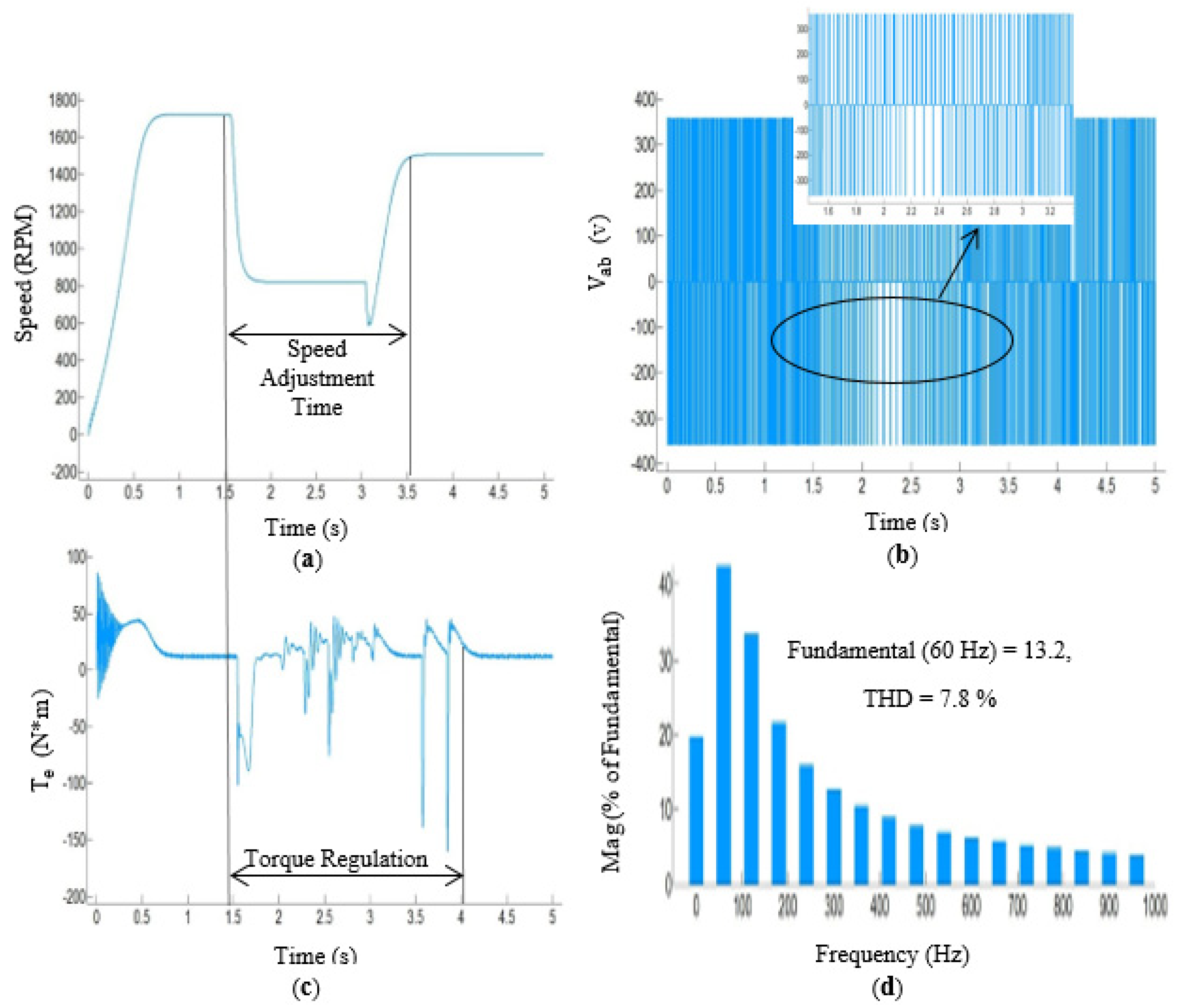
Figure 8 focuses on the transient effect of the load variation on different parameters of the AC motor. In this scenario, the electric load increased one-step from 300 to 500 W per each phase. Figure 8a represents the required time for the control application to regulate the motor speed based on the load variation. Figure 8b indicates the VFD output voltage during the load fluctuation. The results showed an appropriate sine PWM waveform for the induction motor. The fast electromagnetic torque stabilization process appears in Figure 8c. The VFD using DPC and power correction loops programmed on the microcontroller achieved this. Figure 8d illustrates the total harmonic distortion (THD) of the VFD output while the motor was running at 1500 rpm.
7. Implementation and Experiments
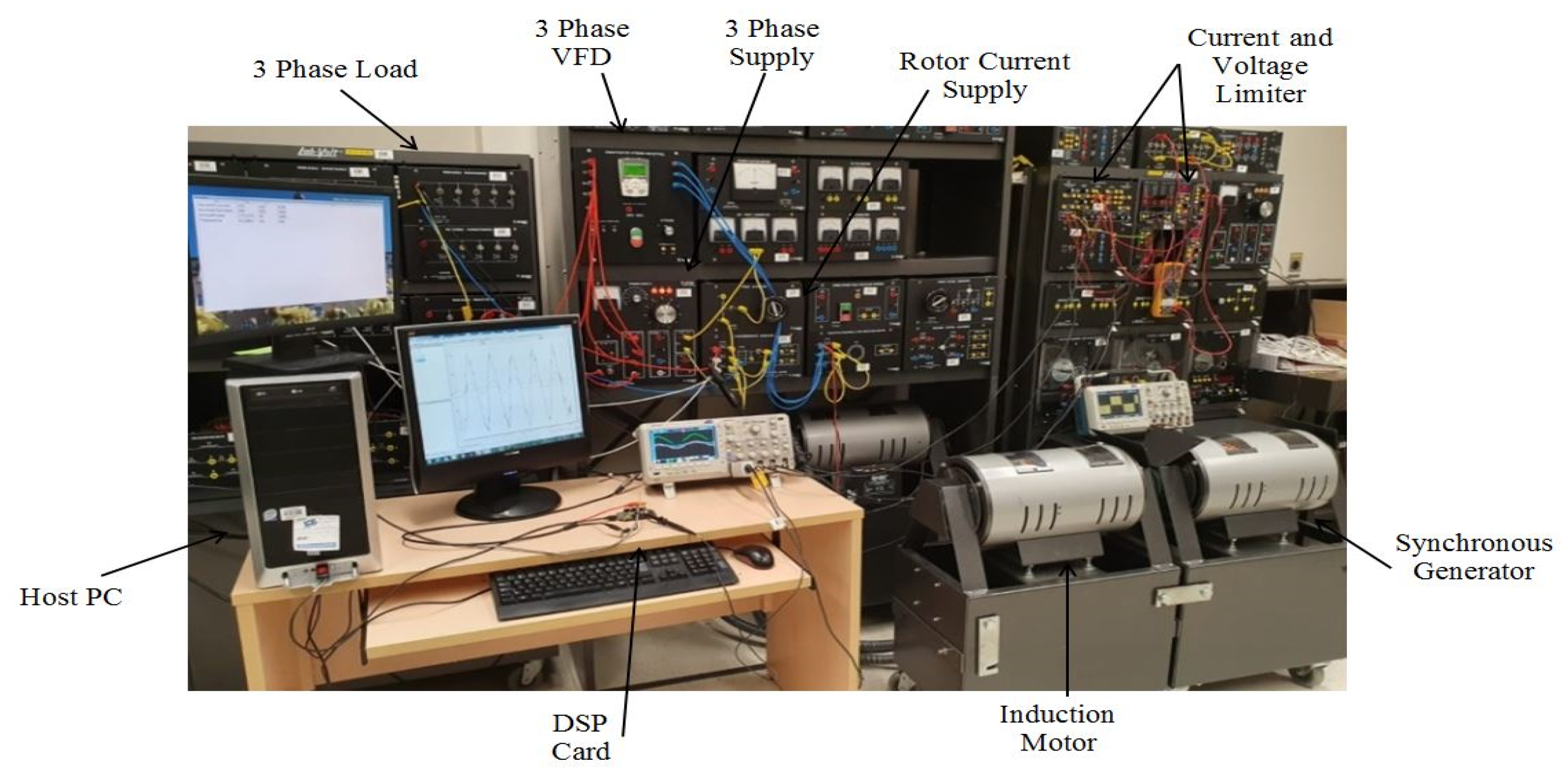
The control algorithm operated on the FDRM-KL25Z signal processor board. The load power tracking control strategy and DPC-PWM were used in this application to achieve a fast and reliable response of motor speed. The experimental setup appears in Figure 9. Table 2 gives more details of the motor speed control application.
As a variable speed diesel generator uses an AC motor to rotate the generator’s stator, we used a synchronous generator as a mechanical load for the induction motor instead of the rotating stator. The induction motor and the synchronous generator were coupled. Consequently, the mechanical load applied on the AC motor shaft varied by changing the electrical load connected to the synchronous generator. The induction motor was equipped with rotor damper winding to limit induced voltage and increase motor torque. The controlled system supplies 208 V at 50/60 Hz and operates at three different rpm steps. In this experiment, electrical loads were manually changed to see the reaction of different components and simultaneously monitor the motor behavior and the control algorithm.
8. Results and Discussion
The results below indicated the response of a 2 kW induction motor during the electric load step variation. The three-phase Fluke multimeter analyzer measured the power quality of the VFD output and motor frequency. In Figure 10, we present the results for two different load power levels. For the first step, the 482 W electric load per phase was applied to the synchronous generator. Based on the conditions defined on the controller, the AC motor speed increased to 1497 rpm. This behaviour proved that motor speed variation followed the control algorithm. While the experiment was running, the electric load was manually reduced to 295 W per phase. Consequently, the control program increased motor speed to 1798 rpm to meet the predetermined operating conditions. Therefore, during low load values, the VSDG speed control was able to compensate for the necessary rpm while the diesel engine slowed down. Figure 10 (a1, b1) represent the motor frequency response, as dictated by the control algorithm conditions. The green and blue graphs shown in Figure 10 (a2, b2) are voltage and current signals coming from signal limiters apparatuses. The pink graph indicates a reference signal produced by the microcontroller itself. The yellow graph shows the load current used by the microprocessor to calculate the instantaneous power.
Table 3 indicates the CM and VFD behavior during electric load switching process between the two conditions defined in the control algorithm implemented in a microcontroller. The three-phase power and its corresponding frequency for different loads appear below. Precise speed adjustment for the CM was achieved using load consumption tracking strategy. Power factors, currents, and harmonics were received from the VFD, and load power was measured separately from the load panel.
9. Experimental Validation
This section presents a comparison between the numerical and experimental simulations of the 2 kW induction motor speed control application. The numerical simulation used MATLAB/Simulink environment following the algorithm described in Section 6.
In Table 4, we present the target speed values of the AC motor for each load and a comparison between the achieved values of the rpm using numerical and experimental approaches. The comparative analysis of load vs rpm showed reliable performance of the control algorithm. During the operation of the test bench, the motor speed increased and decreased several times according to predetermined load variation. Each time, a steady state condition was achieved within 1–3 s, which demonstrated a good synchronicity between the VFD and controlled program in producing electromagnetic torque. This response time showed that the AC motor speed adjusted rapidly in the case of a sudden load change. Finally, the fast and robust response of the AC motor to the load variation resulted in minimum electric disturbances at the VSDG output and motor shaft oscillations.
10. Conclusions
One of the solutions to increase electricity production efficiency using gensets is to use VSDGs. A recently developed technology uses a rotating stator as a solution to allow the diesel engine to slow down and operate at better efficiency with reduced loads. An AC compensator motor drives the generator’s stator and adjusts its speed according to the VSDG electric load such that the stator speed increases when the VSDG electric load decreases. In this paper, we developed a control algorithm for the AC compensator motor that follows the load variation. The numerical and experimental results demonstrated an efficient and robust control algorithm. The main advantages for introducing this control approach with the rotating stator VSDG technology are the increased efficiency operation and reduced fuel consumption and GHG emissions of the diesel engine. The fast time response of the AC motor ensures current quality without the use of complex power electronics.
Author Contributions
Writing the paper, M.M.; experimental design and setup, B.T.; refining the manuscript, M.R. and A.I. All authors have read and agreed to the published version of the manuscript.
Funding
This research received no external funding.
Conflicts of Interest
The authors declare no conflict of interest.
Abbreviations
The following abbreviations are used in this manuscript:
| VSDG | Variable Speed Diesel Generator |
| DG | Diesel Generator |
| DE | Diesel Engine |
| AC | Alternative Current |
| GHG | Greenhouse Gases |
| CVT | Continuous Variable Transmission |
| PID | Proportional Integral and Derivative |
| ED | Electric Drive |
| CM | Compensatory Motor |
| SG | Synchronous Generator |
| DPC | Direct Power Control |
| VSI | Voltage Source Inverter |
| SVM | Space Vector Modulation |
| DQ | Direct Quadrature |
| VSC | Voltage Source Converter |
| RC | Resistor/Capacitor |
| PWM | Pulse Width Modulation |
| IGBT | Insulated-Gate Bipolar Transistor |
| VFD | Variable Frequency Drive |
| ADC | Analog to Digital Converter |
| THD | Total Harmonic Distortion |
| RPM | Revolution Per Minute |
References
- Leuchter, J.; Rerucha, V.; Krupka, Z.; Bauer, P. Dynamic behavior of mobile generator set with variable speed and diesel engine. In Proceedings of the 2007 IEEE Power Electronics Specialists Conference, Orlando, FL, USA, 17–21 June 2007; pp. 2287–2293. [Google Scholar]
- Ibrahim, H.; Younès, R.; Basbous, T.; Ilinca, A.; Dimitrova, M. Optimization of diesel engine performances for a hybrid wind–diesel system with compressed air energy storage. Energy 2011, 36, 3079–3091. [Google Scholar] [CrossRef]
- Kawabata, Y.; Oka, T.; Ejiogu, E.; Kawabata, T. Variable speed constant frequency stand-alone power generator using wound-rotor induction machine. In Proceedings of the 4th International Power Electronics and Motion Control Conference (IPEMC 2004), Xi’an, China, 14–16 August 2004; Volume 1773, pp. 1778–1784. [Google Scholar]
- Lee, J.; Lee, S.; Sul, S. Variable-Speed Engine Generator With Supercapacitor: Isolated Power Generation System and Fuel Efficiency. IEEE Trans. Ind. Appl. 2009, 45, 2130–2135. [Google Scholar] [CrossRef]
- Brace, C.; Deacon, M.; Vaughan, N.; Horrocks, R.; Burrows, C. An operating point optimizer for the design and calibration of an integrated diesel/continuously variable transmission powertrain. Proc. Inst. Mech. Eng. Part D J. Automob. Eng. 1999, 213, 215–226. [Google Scholar] [CrossRef]
- Brown, D. Variable Speed Gensets; CVT Corp: Intelligent Energy Systems, LLC: Anchorage, AK, USA, 2013; pp. 1–17. [Google Scholar]
- Pena, R.; Clare, J.; Asher, G. Doubly fed induction generator using back-to-back PWM converters and its application to variable-speed wind-energy generation. IEE Proc. Electr. Power Appl. 1996, 143, 231–241. [Google Scholar] [CrossRef] [Green Version]
- Waris, T.; Nayar, C.V. Variable speed constant frequency diesel power conversion system using doubly fed induction generator (DFIG). In Proceedings of the 2008 IEEE Power Electronics Specialists Conference, Rhodes, Greece, 15–19 June 2008; pp. 2728–2734. [Google Scholar]
- Ferdiansyah, I.; Rusli, M.R.; Praharsena, B.; Toar, H.; Ridwan; Purwanto, E. Speed Control of Three Phase Induction Motor Using Indirect Field Oriented Control Based on Real-Time Control System. In Proceedings of the 2018 10th International Conference on Information Technology and Electrical Engineering (ICITEE), Kuta, Indonesia, 24–26 July 2018; pp. 438–442. [Google Scholar]
- Ahmad, M. Vector Control of Induction Motor Drives. In High Performance AC Drives: Modelling Analysis and Control; Springer: Berlin/Heidelberg, Germany, 2010; pp. 47–75. [Google Scholar]
- Chattopadhyay, A. Advances in vector control of ac motor drives—A review. Sadhana-Acad. Proc. Eng. Sci. 1997, 22, 797–820. [Google Scholar] [CrossRef]
- Achanta, R.K.; Pamula, V.K. DC motor speed control using PID controller tuned by jaya optimization algorithm. In Proceedings of the 2017 IEEE International Conference on Power, Control, Signals and Instrumentation Engineering (ICPCSI), Chennai, India, 21–22 September 2017; pp. 983–987. [Google Scholar]
- Doan, P.T.; Bui, T.L.; Kim, H.K.; Kim, S.B. Sliding-mode observer design for sensorless vector control of AC induction motor. In Proceedings of the 2013 9th Asian Control Conference (ASCC), Istanbul, Turkey, 23–26 June 2013; pp. 1–5. [Google Scholar]
- Wang, X.; Reitz, M.; Yaz, E.E. Field Oriented Sliding Mode Control of Surface-Mounted Permanent Magnet AC Motors: Theory and Applications to Electrified Vehicles. IEEE Trans. Veh. Technol. 2018, 67, 10343–10356. [Google Scholar] [CrossRef] [Green Version]
- Singh, B.N.; Singh, B.; Singh, B.P. Performance analysis of a closed-loop field oriented cage induction motor drive. Electr. Power Syst. Res. 1994, 29, 69–81. [Google Scholar] [CrossRef]
- Kővári, A.; Schmidt, I.; Kádár, I. Current-control of induction motor drives: Comparison of inverter control methods. In Proceedings of the IEEE Postgraduate Conference on Electric Power Systems, Budapest, Hungary, 11–14 August 2002; pp. 45–50. [Google Scholar]
- Mitronikas, E.D.; Safacas, A.N. An improved sensorless vector-control method for an induction motor drive. IEEE Trans. Ind. Electron. 2005, 52, 1660–1668. [Google Scholar] [CrossRef]
- Mobarra, M.; Issa, M.; Rezkallah, M.; Ilinca, A. Performance Optimization of Diesel Generators Using Permanent Magnet Synchronous Generator with Rotating Stator. Energy Power Eng. 2019, 11, 24. [Google Scholar] [CrossRef] [Green Version]
- Mobarra, M.; Fiset, J.; Ilinca, A. Modeling and optimization of the energy production based on Eo-Synchro. Power Eng. 2017, 3, 3–9. [Google Scholar]
- Issa, M.; Fiset, J.; Ibrahim, H.; Ilinca, A. Eco-Friendly Selection of Diesel Generator Based on Genset-Synchro Technology for Off-Grid Remote Area Application in the North of Quebec. Energy Power Eng. 2019, 11, 16. [Google Scholar] [CrossRef] [Green Version]
- Issa, M.; Ibrahim, H.; Lepage, R.; Ilinca, A. A Review and Comparison on Recent Optimization Methodologies for Diesel Engines and Diesel Power Generators. J. Power Energy Eng. 2019, 7, 31. [Google Scholar] [CrossRef] [Green Version]
- Issa, M.; Fiset, J.; Mobarra, M.; Ibrahim, H.; Ilinca, A. Optimizing the performance of a 500kW Diesel Generator: Impact of the Eo-Synchro concept on fuel consumption and greenhouse gases. Power Eng. 2018, 23, 22–31. [Google Scholar]
- Issa, M.; Ait-Yahia, K.; Lepage, R.; Ibrahim, H.; Ilinca, A.; Ghandour, M. Integrated A Variable Frequency Drive for a Diesel-Generating Set Using the Genset-Synchro Concept. Int. J. Eng. Res. Technol. 2019, 8, 232–239. [Google Scholar]
- Fiset, J. Mechanical Regulation of Electrical Frequency In An Electrical Generation System. Canadian Intellectual Property Office-Patent No. 2697420, 22 February 2010. [Google Scholar]
- Thomas Howard, B. Variable Frequency Drive Systems. In Energy Production Systems Engineering; IEEE: Hoboken, NJ, USA, 2017; pp. 441–466. [Google Scholar]
- Ejlali, A.; Khaburi, D.A. Power quality improvement using nonlinear-load compensation capability of variable speed DFIG based on DPC-SVM method. In Proceedings of the 5th Annual International Power Electronics, Drive Systems and Technologies Conference (PEDSTC 2014), Tehran, Iran, 5–6 February 2014; pp. 280–284. [Google Scholar]
- Malinowski, M.; Jasinski, M.; Kazmierkowski, M.P. Simple direct power control of three-phase PWM rectifier using space-vector modulation (DPC-SVM). IEEE Trans. Ind. Electron. 2004, 51, 447–454. [Google Scholar] [CrossRef]
- Petruzella, F. Electric Motors and Control Systems; McGraw-Hill, Inc.: New York, NY, USA, 2009. [Google Scholar]
- Ali, Y.; Noor, S.; Bashi, S.; Hassan, M. Microcontroller performance for DC motor speed control system. In Proceedings of the National Power Engineering Conference (PECon 2003), Bangi, Malaysia, 15–16 December 2003; pp. 104–109. [Google Scholar]
Figure 1.
Configuration of the variable speed diesel generator (VSDG).

Figure 2.
Architecture of the VSDG with rotating stator.

Figure 3.
Direct power control of the induction motor (IM) based on sensor-less space vector modulation (SVM) applied to the VSDG.
Figure 3.
Direct power control of the induction motor (IM) based on sensor-less space vector modulation (SVM) applied to the VSDG.

Figure 4.
Closed-loop control diagram of variable speed motor application.

Figure 5.
Domain and frequency definition on a 12 bit analog-to-digital conversion board (ADC).

Figure 6.
Autonomous AC motor speed control algorithm based on variable input surveillance.

Figure 7.
Received signals from motor phase terminal voltages and currents.

Figure 8.
Transient effect of load variation on: (a) motor speed; (b) variable frequency drive (VFD) phase-to-phase output voltage; (c) motor electric torque; and (d) current harmonic distortion rate.
Figure 8.
Transient effect of load variation on: (a) motor speed; (b) variable frequency drive (VFD) phase-to-phase output voltage; (c) motor electric torque; and (d) current harmonic distortion rate.

Figure 9.
Hardware implementation.

Figure 10.
Results for the 2 kW AC motor speed control application using the FDRM-KL25Z DSP card; (a1,b1) motor frequency response to sudden increase/decrease of electric load; (a2,b2) voltage (green) and current (blue) response to sudden increase/decrease of the load (reference signal of microcontroller in pink and load current in yellow).


Table 1.
Supplementary details of Figure 7.
Table 1.
Supplementary details of Figure 7.
| RPM | Sample Counter | Number Samples | Active Power | Frequency | Figure 7 |
|---|---|---|---|---|---|
| 1200 | 126 unit | 245 DEC | 653.736 W | 40.8163 Hz | a |
| 1500 | 120 unit | 197 DEC | 485.672 W | 50.7614 Hz | b |
| 1800 | 118 unit | 169 DEC | 270.041 W | 59.1716 Hz | c |
Table 2.
Parameters of variable speed induction motor.
| Application Specification | Quantity |
|---|---|
| Squirrel-Cage Motor | 2 KW |
| pole | 4 |
| Stator Winding | Star or Delta |
| Torque | 10.8 N·m |
| Efficiency | 80% |
| Microcontroller Card | FRDM-KL25Z |
| Frequency | 48MHz |
| Sensor | MMA8451Q |
| Connectivity | MCU IMCU I/O |
| Power Converter | ABB ACS355-0 3E |
| PN | 4 KW (5HP) |
| U1 | 3–400 V/ 480 V |
| I1 | 14 A /6.4 A |
| f1 | 48–63 Hz |
| Variable Resistance | 2 KW |
| Resistance | 240/120/60/60/30 Ω |
| Accuracy | 5% |
| Nominal Voltage | 120 V—AC/DC |
| Current/Voltage Isolator | 0.2 KW |
| Maximum Continuous Current | 1/5 A |
Table 3.
Measured values of the induction motor and VFD output voltage.
| Phase A | Phase B | Phase C | ||||
|---|---|---|---|---|---|---|
| Power (KW) | 0.482 | 0.259 | 0.527 | 0.276 | 0.433 | 0.295 |
| Current (A) | 7 | 5 | 9 | 6 | 7 | 4 |
| Frequency (Hz) | 49.24 | 59.96 | 49.24 | 59.96 | 49.24 | 59.96 |
| Harmonic (%) | 7.3 | 7.7 | 7.3 | 7.7 | 7.3 | 7.7 |
| V (RMS) | 119.37 | 121.34 | 119.3 | 121.7 | 119.4 | 122.2 |
| Power Factor | 0.69 | 0.61 | 0.63 | 0.38 | 0.41 | 0.37 |
Table 4.
Validation results.
| Speed (rpm) | 1000 | 1200 | 1500 | 1800 |
| Load Power Per Phase (W) | 1000 | 600 | 400 | 200 |
| Numerical (rpm) | 971 | 1182 | 1482 | 1792 |
| Experiment (rpm) | 955 | 1167 | 1497 | 1798 |
| Error % | 1.64 | 1.26 | 1.01 | 0.33 |
© 2020 by the authors. Licensee MDPI, Basel, Switzerland. This article is an open access article distributed under the terms and conditions of the Creative Commons Attribution (CC BY) license (http://creativecommons.org/licenses/by/4.0/).
Share and Cite
MDPI and ACS Style
Mobarra, M.; Tremblay, B.; Rezkallah, M.; Ilinca, A. Advanced Control of a Compensator Motor Driving a Variable Speed Diesel Generator with Rotating Stator. Energies 2020, 13, 2224. https://0-doi-org.brum.beds.ac.uk/10.3390/en13092224
AMA Style
Mobarra M, Tremblay B, Rezkallah M, Ilinca A. Advanced Control of a Compensator Motor Driving a Variable Speed Diesel Generator with Rotating Stator. Energies. 2020; 13(9):2224. https://0-doi-org.brum.beds.ac.uk/10.3390/en13092224
Chicago/Turabian StyleMobarra, Mohammadjavad, Bruno Tremblay, Miloud Rezkallah, and Adrian Ilinca. 2020. "Advanced Control of a Compensator Motor Driving a Variable Speed Diesel Generator with Rotating Stator" Energies 13, no. 9: 2224. https://0-doi-org.brum.beds.ac.uk/10.3390/en13092224
Note that from the first issue of 2016, this journal uses article numbers instead of page numbers. See further details here.