Ηydrodynamic Response and Produced Power of a Combined Structure Consisting of a Spar and Heaving Type Wave Energy Converters


Department of Civil Engineering and Geomatics, Cyprus University of Technology, Limassol 3036, Cyprus
Energies 2021, 14(1), 225; https://0-doi-org.brum.beds.ac.uk/10.3390/en14010225
Submission received: 30 November 2020
/
Revised: 21 December 2020
/
Accepted: 29 December 2020
/
Published: 4 January 2021
(This article belongs to the Special Issue Power System Dynamics and Renewable Energy Integration)
Abstract
:During the past years, researchers have studied both numerically and experimentally multibody wave-wind combined energy structures supporting wind turbines and different types of Wave Energy Converters (WECs); rigid body hydrodynamic assumptions have been adopted so far for the development of their numerical models and the assessment of their produced power. In the present paper a numerical model that is based on the use of generalized modes addressing wave-structure interaction effects for the case of a multibody wave-wind combined structure is developed and presented. Afterwards, the developed numerical model is used for the assessment of the hydrodynamic response and the prediction of the produced power of different possible configurations of the updated WindWEC concept which consists of a spar supporting a wind turbine and one, two, three or four heaving type WEC buoys. The combined effects of the center-to-center distance of the WEC and spar platform, the number of the WECs and the grid configuration of spar and WECs on the hydrodynamic interaction between the different floating bodies, spar and WEC buoys, and consequently on their response and wave power production are examined for regular and irregular waves. Strong hydrodynamic interaction effects exist for small distance between spar and WECs that result to the decrease of the produced power. Power matrices of the updated WindWEC concept are presented for all examined configurations with different number of WECs. Moreover, the annual produced power of the updated WindWEC in two sites is estimated and presented. The generalized modes analysis presented in this paper is generic and can be used for the early stage assessment of wave-wind combined energy structures with low computational cost. The updated WindWEC can be used in sea sites with different environmental characteristics while extracting valuable amount of wave power.
1. Introduction
Offshore Wind Turbines (OWTs) technology can be considered as the leading technology in the ocean renewable energy sector, which has the greatest potential for being developed extensively in the years to come and become the backbone of the global energy system. New offshore wind farms are now in operation or are scheduled for development in the coming years [1]. Floating OWTs can be effectively used as an alternative to the fixed bottom OWTs in intermediate and deep water areas. Among several concepts proposed so far Hywind is a successful example already in operation off the north-east coast of Scotland [2] in the world’s first floating wind farm.
On the other hand, Wave Energy Converters (WECs) after forty years of unsuccessful wide industrialization are in a reconsideration phase as far as numerical analysis and design methods that should be used. Many different types of WECs have been proposed so far by a big number of researchers during the past decades [3,4,5]. Wavestar [6,7] is a good WEC example that may efficiently produce electricity due to the simple mode of operation. Although the WECs were proposed earlier than OWTs, offshore wind technology experienced a very rapid and intense growth. The maturity of OWTs and WECs is different although both are subjected to similar challenges related with the harsh marine environment and hydrodynamic loadings.
It might be beneficial to investigate the possibility of extracting ocean energy resources, offshore wind and wave energy, simultaneously by sharing common marine infrastructures aiming to reduce the overall cost to increase the advantage use of the resources to ensure the efficient use of the ocean space [8,9,10,11]. Combining WECs with OWTs may result in several advantages including the possible reduction of construction, installation and maintenance costs related with infrastructures, equipment, mooring and anchoring systems, subsea power cables, survey and monitoring methods, and power storage. Also, the combined production of wind and wave energy may result in power output smoothing and in zero produced power reduction as the frequency range of the fluctuation in mean produced power by the OWTs greatly differs from the relevant range produced by WECs. Moreover, the WECs may act as a damper for the OWT system while harnessing the incoming wave loads. Several researchers [12,13,14,15,16,17,18] have studied numerically and experimentally wave-wind combined energy concepts utilizing different floating support platforms with different WEC types. An innovative wave-wind combined concept that consists of the Hywind spar and one Wavestar type WEC has been introduced in [19] and named as WindWEC is very critical at the beginning of the development of a specific concept basic questions about the effect of the number of the WECs as well as the effect of the distance between the different bodies to be on the hydrodynamic response of both spar and WECs and produced power to be addressed.
The design and analysis of combined energy structures present increasing complexity and require efficient computational models and numerical analysis methods as well as suitable physical model tests to ensure structural integrity and efficient performance. For the implementation of the numerical analysis of the combined concept that is a multibody marine structure, in time or in frequency domain, rigid body hydrodynamic assumptions and interconnected bodies with flexible or rigid elements have been very commonly adopted and used [14,15,16,17]. Excitation wave loads and hydrodynamic coefficients between the different interconnected bodies are calculated based on the six rigid body degrees of freedom for each body and relevant hydrodynamic analysis.
Generalized modes analysis has been developed by [20] and is mainly used to describe structural deformations of floating structures [21], motions of hinged and/or interconnected bodies [22,23,24], hydroelasticity of floating structures [25,26] and viscous dissipation in relation with marine engineering problems [27].
In the present paper, the dynamic characteristics and the wave power performance of the updated wave-wind combined concept WindWEC is presented for different possible design configurations. Updated WindWEC consists of a spar supporting a wind turbine and one, two, three or four heaving type WECs in different grid configurations. For estimating the hydrodynamic response and the produced wave power, a numerical model has been developed and presented which is based on the use of generalized modes. Spar oscillates in the six rigid body degrees of freedom while WECs are oscillating in two additional generalized modes, one of which related to the produced wave power. Details about the development of the generic generalized modes analysis are presented at the beginning of the paper. Afterwards with the use of the proposed numerical model, the effects of the total number of floating bodies comprising WindWEC, and consequently its grid configuration, and of the center-to-center distance between the bodies on the hydrodynamic interaction effects and on the produced wave power are examined. Strong hydrodynamic interaction effects exist for small distance between the spar and WECs resulting to the decrease of the produced power and should be avoided. The examined configuration with four WECs results to the largest produced wave power. Power matrices of the updated WindWEC concept are presented for all examined configurations with different number of WECs. The increase of the number of the bodies, and consequently the increase of the hydrodynamic interaction between the different bodies, results to the decrease of the produced power if the distance between the spar and the different bodies remains the same. Moreover, the annual produced power of the updated WindWEC in two different sea sites is estimated and presented in order a direct estimation of the expected annual produced power of the updated WindWEC to be presented. An early-stage assessment of the updated combined concept WindWEC with low computational cost has been achieved with the use of the generalized modes analysis developed and presented in this paper.
2. Numerical Modeling of Wave-Wind Combined Structures with the Use of Generalized Modes
The numerical modeling that will be presented in this section is generic and can be applied for combined concepts consisting of different bodies for the evaluation of their wave-structure interaction effects and produced power. Also, it can be used if hydroelasticity is important for one or more of the bodies of the combined structure. In the present paper the developed numerical modeling is used for the case of the WindWEC concept combining the technologies of Hywind OWT and a heaving type WEC. WindWEC was introduced in [19] and originally analyzed as a two-body structure consisting of the spar platform and one WEC in time domain with rigid body hydrodynamic assumptions for everybody. A schematic layout of the original design configuration of WindWEC combined concept is presented in Figure 1.
In the present paper and contrary to the original design of WindWEC [19] the combined concept consists of the moored spar-type floating wind turbine Hywind OWT and one, two, three or four heaving type WECs. Four different possible grid configurations of WindWEC have been examined consisting of two, three, four and five bodies in total. The spar platform is capable to carry the NREL 5MW wind turbine for offshore applications. The WEC used in the present paper has a cylindrical geometry with a conical bottom end and its relative dimensions compared to the spar floating structure are small (2.2% of the total spar displacement and 2.1% of the spar mass); it is noted that this type of WEC is based on the design philosophy of Wavestar but is not exactly the same. Details and characteristics about the platform, wind turbine and WECs are presented in Table 1. For both spar and WECs similar design characteristics have been used compared to the unit characteristics as proposed in the original design of this combined concept in [19]. It should be noted that for the calculation of the characteristics, and when it is necessary, the coordinate system in which the characteristics are calculated is at the mean water level of each body with the Z-axis pointing upward and X-axis to the right. For the calculation of the characteristics the hull of the spar (including ballast and steel weight), rotor, nacelle and tower are accounted for.
The spar platform and the WEC buoys are interconnected through a rigid structural arm (e.g., a frame structure or a rigid bar) that allows the WECs to move relatively with the spar platform in different degrees of freedom that can be adjusted. In the present paper we consider that WECs can move freely related with the spar’s motions in heave and pitch degrees of freedom. The structural configuration (e.g., connectors, steel thickness, dimensions), as well as the final engineering design of the arm, is out of the scope of the present paper. Moreover, it is assumed that the arm can withstand all the internal loads without any structural integrity problems and behaves rigidly. The Power Take-Off (PTO) that transforms the relative heave motion of the two bodies, WEC and spar, into useful power is positioned at the edge of the rigid structural arm and behaves as a linear damper. It is stated that PTO stiffness effects have not been examined in the present paper. On the other hand, the spar is considered to move in six rigid body degrees of freedom.
The multibody hydrodynamic analysis of the WindWEC subjected to incident regular waves is conducted in the frequency domain and is based on the three-dimensional linear wave diffraction theory appropriately modified to account generalized modes for the representation of the motions of WECs. The hydrodynamic analysis of the WindWEC is taking into account the hydrodynamic interaction between the WECs and spar. The six degrees of freedom of the spar, namely, surge (ξ1), sway (ξ2), heave (ξ3), roll (ξ4), pitch (ξ5) and yaw (ξ6) are numerically simulated as six rigid body degrees of freedom while the two degrees of freedom of each of the WECs are numerically simulated as: (a) two additional generalized modes ξj, j = 7 and 8, for the case that WindWEC consists of one WEC, (b) four additional generalized modes ξj, j = 7, 8, 9 and 10, for the case that WindWEC consists of two WECs, (c) six additional generalized modes ξj, j = 7, 8, 9, 10, 11 and 12, for the case that WindWEC consists of three WECs and (d) eight additional generalized modes ξj, j = 7, 8, 9, 10, 11, 12, 13 and 14, for the case that WindWEC consists of four WECs. As a result, and for the grid configuration that WindWEC consists in total of two bodies, spar and one WEC, the total degrees of freedom of the numerical model are eight, namely, the six rigid body degrees of the spar platform, ξ1, ξ2, ξ3, ξ4, ξ5 and ξ6, and the two generalized modes of each WEC, ξ7 and ξ8, representing heave and pitch of the WEC, respectively. Same considerations apply to the rest examined configurations with three, four and five bodies with eight, ten, twelve and fourteen total degrees of freedom, respectively.
Based on linear potential theory, the flow is assumed irrotational and incompressible. The fluid is considered inviscid while its motion can be described with the use of the velocity potential. The velocity potential, φ, satisfies the Laplace equation, and is described as below:
where φ0 is the potential of the incident waves, φD is the diffraction potential, φs is the scattered potential due to WECs and spar, φj, j = 1,…, N, is the radiation potential of each mode associated with the waves that are radiated due to the forced motions of the floating bodies (six rigid body degrees of freedom of spar and additional generalized modes of WECs), ξj j = 1,…, N, are the complex amplitudes of the degrees of freedom of the combined structure, ω is the wave frequency, g is the gravitational acceleration, and N is the number of the total degrees of freedom (e.g., N = 8, 10, 12 and 14 for two, three, four and five bodies, respectively, as discussed previously). For φj, j = 1,…,6, the radiation potential corresponds to the rigid body degrees of freedom of the spar. While, for φj, j = 7,…, N, the potential is related only with the additional generalized modes that correspond to the heave and pitch motions of the WECs.
The boundary value problem is solved based on the three-dimensional panel method utilising Green’s theorem. Appropriate boundary conditions are used on the free surface, on the sea bottom, and on the floating body, and the radiation condition for the outgoing waves is adopted [20,24]. Τhe velocity potential ϕ should satisfy the Laplace equation and the following linearized boundary conditions (2–5):
where Equation (2) is the combined kinematic and dynamic free-surface condition, k is the wave number, Equation (3) is the bottom boundary condition for depth d, and Equations (4) and (5) are the Neumann conditions, which should hold on the wet surfaces of all the bodies of the combined structure with nj denoting the normal unit vector of the bodies for all j degrees of freedom in the vertical direction.
The additional generalized degrees are numerically defined as a unit deformation of all panels of the wet surface of the WEC in the specific degree of freedom; e.g., for the 7th degree of freedom all the panels of the wet surface of the WEC obtain a value equals to one in heave direction only. The radiation potential for all modes, φj, j = 1,…, N, is subjected to the following boundary condition on the WECs and spar body [20]:
where nx, ny, nz are the unit normal vectors on the wet surface of the body and uj, vj, wj are the components of the displacement vector of the generalized mode φj, j = 1,…, N in x, y, z directions, respectively; e.g., for the 7th degree of freedom the displacement vector is u7 = 1, v7 = 0 and w7 = 0.
For both the spar and the WEC bodies, uniform mesh is used for the panel model discretization of their wet surface. The number of panels is selected after an appropriate convergence study. The amplitudes of all body’s motions, ξj, j = 1,…, N, (rigid body and additional generalized) are calculated from the solution of the following linear system of equations (for i = 1,…, N):
where Mij and Kij,i, j = 1,…, N, are the entire mass of the system and stiffness elements in all degrees of freedom. With regards to the hydrodynamic coefficients, namely, added mass, Aij, i, j = 1,…, N, radiation damping, Bij, and wave excitation loads, Xi, are calculated after the solution of the first-order boundary value problem according to the following equations:
where ni, i = 1,…, N, is the normal component of the i-th mode shape (both rigid body and generalized degrees of freedom) on the mean body wetted surface, SB, and ρ is the mass density of the water. Moreover in Equation (4), Cij, i, j = 7,…, N, are the coefficients of the hydrostatic stiffness matrix given with the use of the following equation [20]:
where dr is the draft of the floating body, Di is the divergence of the displacement vector, and ρs and ρ are the mass density of the structure and the water, respectively.
With regard to the PTO damping elements, , and since the PTO function is related with the heave motion of the WECs, the coefficients that are nonzero are related with the heave degree of freedom of the WECs. It is stated that the present paper emphasizes on the hydrodynamic analysis of this type of the combined structure; aerodynamic damping loads or structural viscous loads are not considered during the analysis. In the present paper four different configurations of the combined concept will be examined consisting of one, two, three and four WECs. As a result, and for the case that the combined concept consists of four WECs and the spar, the degrees of freedom of the numerical model that correspond to the heave motion of the WECs are the 7th, 9th, 11th and 13th. Similar considerations can be made for the case that the combined concept consists of different number of WECs. The elements depending to the number of WECs that are used are calculated as follow:
or
The response of the floating body in all the examined degrees of freedom, rigid and additional generalized modes, is expressed in terms of the Response Amplitude Operator, RAO, (Equation (13)):
where is the amplitude of the complex quantity ξj and A is the amplitude of the incident waves defined at the beginning of the analysis equal to one.
The time-averaged produced wave power, , of the k-th WEC extracted from the regular waves is calculated with the following Equation [28]:
where j depends upon the WEC that produces power. The total produced power, , of the WindWEC is:
where n is the total number of WECs that are used for the examined configuration of WindWEC. The time averaged power output for irregular waves is calculated as:
where is the total produced power of WindWEC for ω wave frequency, is a power spectrum, Hs is the significant wave height and Tp is the peak wave period. For the purposes of the present paper the Pierson-Moskowitz spectrum is adopted as below:
where βJ is a factor that depends upon the γ factor that is considered equal to 3.3 and σ a constant value depends upon the wave frequency.
Finally, the annual averaged produced power of WindWEC for a specific sea site is calculated as follows:
where is the probability of occurrence that corresponds to the wave climate at a specific ocean site defined as a set of sea states related with the significant wave height and wave energy period.
3. Examined Configurations of WindWEC
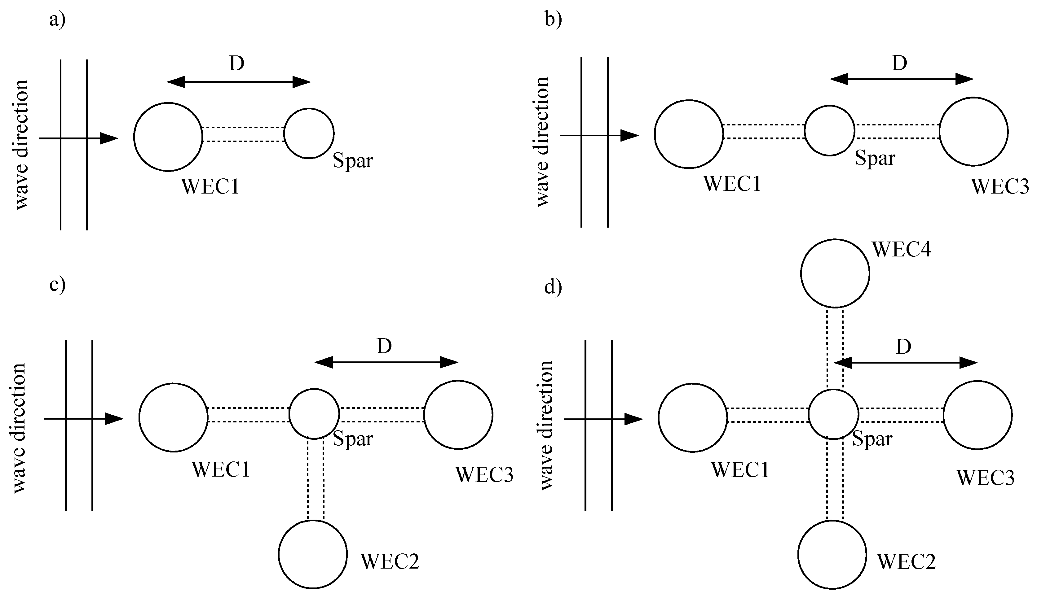
As far as the examined wave environment, the combined multibody structure is placed in infinite water depth (deep water approximations) while the incident wave direction equals to 0° (surge motion of spar aligns with wave direction) (Figure 2). Forty-seven wave periods are totally examined between 3 and 24 s and the amplitude of incident waves, A, is considered equals to 1.
Four different configuration cases of the WindWEC, CFi, i = 1~4 are examined (Figure 2). The examined configuration CF1 consists of the spar platform and WEC1, configuration CF2 consists of the spar platform, WEC1 and WEC3, CF3 consists of the spar platform, WEC1, WEC2 and WEC3, and CF4 consists of the spar platform, WEC1, WEC2, WEC3 and WEC4. In all the examined cases, D is the center-to-center distance between the spar platform and WECs. Four different D values are examined for each of the configurations equal to 10 m, 20 m, 30 m and 40 m in order to study the combined effect of the D value and grid configuration on the hydrodynamic response of WindWEC and the produced wave power. In total four configurations and four D values have been examined in the present paper resulting to 16 different examined cases; one of the examined configurations corresponds to the original design of WindWEC. The examined configurations, as well as their total degrees of freedom, are presented in Table 2. The examined configurations correspond to the case with two, three, four and five bodies with eight, ten, twelve and fourteen degrees of freedom, respectively. In all examined cases the first six degrees of freedom correspond to the rigid body degrees of freedom of spar. The natural periods of heave and pitch motions of both spar and WEC are presented in Table 3.
A constant value of BPTO has been selected for all the examined cases which is equal with the radiation damping of the WEC for its natural period in heave degree of freedom, [29] in order maximum energy absorption to be achieved at the natural period of a single WEC. Based on relevant hydrodynamic analysis the heave radiation damping that corresponds to Tn3 = 4.25 s is used. The damping coefficient that is used for all the examined cases in the present paper equals to BPTO = 88,482.7 Nm/s.
4. Results and Discussion
With the examined configurations studied in the present paper the effect of the position of the WECs concerning the spar and the effect of grid configuration are intended to be highlighted. Those configurations will be feasible with an appropriate mooring system design in order to stabilize the combined structure. In the following subsections the results of the generalized modes based numerical model are presented and discussed. Initially hydrodynamic coefficients, namely, the added mass, radiation damping and excitation wave loads, are presented for different WindWEC configurations and D values. Next, results are presented for the motions of WECs and spar as well as for the produced wave power by the WECs focusing on examining the effects of the D values between spar and WECs for a specific configuration, as well as, of the different grid configurations of the WindWEC.
In Figure 3 the heave added mass coefficients are presented for different WECs and examined configurations. The 7th degree of freedom corresponds to the heave generalized mode of the WEC1 for all the examined configurations. The heave added mass coefficient of the WEC considered as a single body (without any interaction effect) is also presented in Figure 3 with a black solid line. For WEC1 (Figure 3a,b) and for all examined cases a large interaction effect of the A77 added mass coefficient exists for all examined wave periods and for the case where the center-to-center distance D equals to 10 m. For the same D value and compared to the heave added mass coefficient of the single WEC the differences are large for all examined configurations CF1, CF2, CF3 and CF4. For D = 10 m and as the number of the bodies consisting WindWEC increases, the effects on the A77 added mass coefficient are larger for all examined wave periods attributed to the intense hydrodynamic interaction. For the rest examined center-to-center distances, namely, 20 m, 30 m and 40 m the A77 coefficients are different compared to the added mass coefficient of a single WEC for wave periods smaller than 14 s. Large differences are observed close to the natural period Tn3 of the WEC; as the distance D increases the resonant effects become smaller.
Similar observations exist for WEC2 of CF3 and CF4 configurations (Figure 3c), and WEC3 of CF2 and CF4 configurations (Figure 3d) regarding the heave added mass coefficient of the WECs; for D = 10 m the effects are large and observed for all the examined wave periods while for the rest examined D values the interaction effects exist for wave periods smaller than 14 s. As far as the heave added mass coefficients of the spar, A33, of the combined concept WindWEC the effect of the configuration and number of bodies of WindWEC on the A33 coefficient (Figure 4a) is large only for the case of CF4 configuration consisting of five bodies and mainly for D = 10 m and D = 20 m, while for the pitch degree of freedom (Figure 4b) the effect of the number of bodies of WindWEC on the A55 coefficient is not significant even for the case of small D values and CF4 where strong interaction effects exist. With regards to the pitch motion of WEC1 which is the 8th degree of freedom in the numerical analysis model of WindWEC, the A88 coefficient of CF1 and CF4 (Figure 4c) is largely affected mainly for small center-to-center distances, D = 10 m and D = 20 m, between WECs and spar.
Apart from the diagonal terms of the added mass matrix that are affected by the WindWEC configuration and distance between the different bodies comprising the combined structure, the non-diagonal terms of the added mass matrix are affected too and should be accounted when dealing with the analysis of wind-wave combined structures. In Figure 4d the A73 coefficient for WEC1 of CF1 and CF4 are presented for all examined D values; A73 is the added mass coefficient of heave motion of WEC1 due to the heave motion of the spar. Large effects exist for all examined wave periods attributed to both the D value and the configuration of WindWEC.
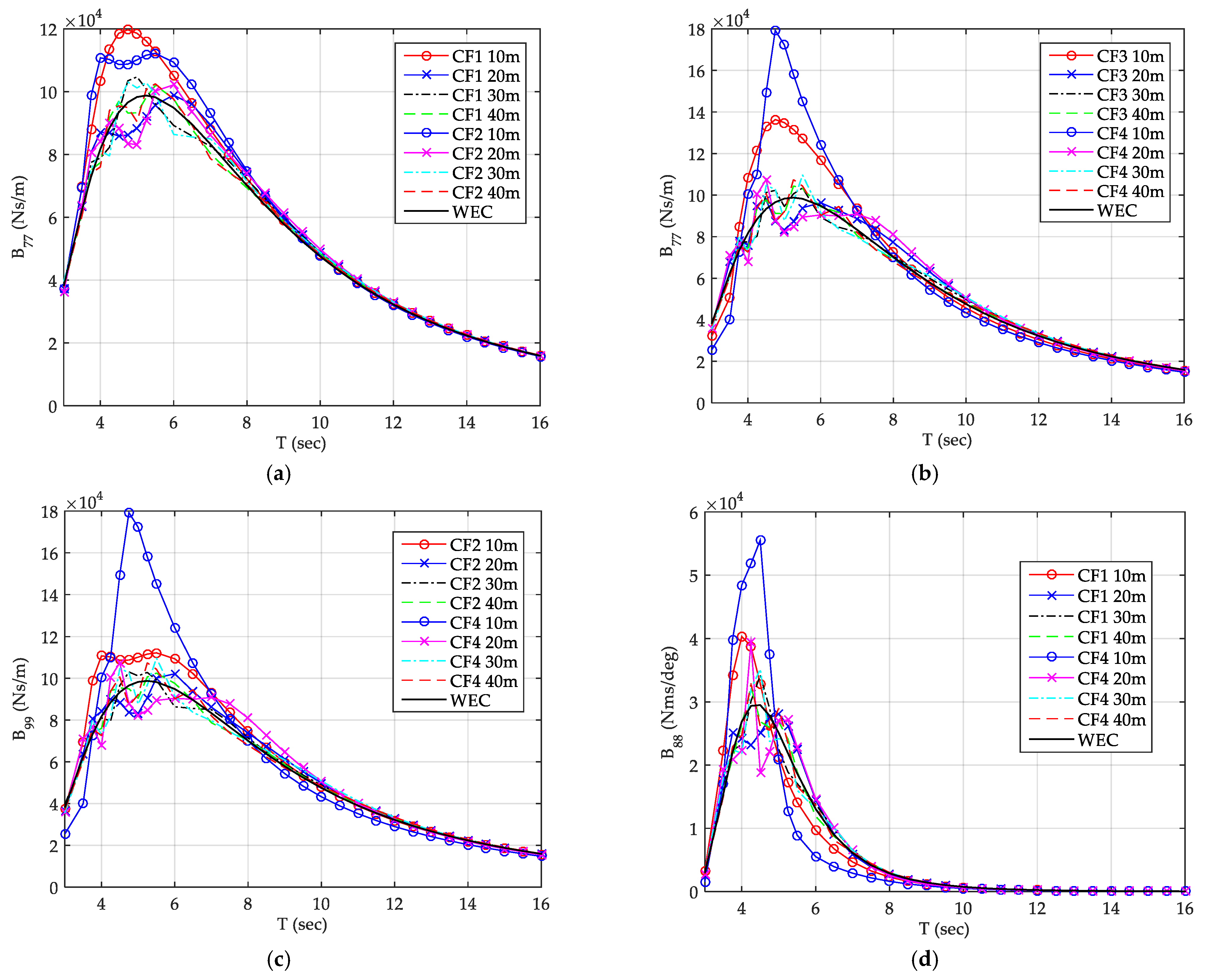
In Figure 5a,b the heave radiation damping coefficients are presented for WEC1 and all examined configurations. It is stated that in all the Figures the heave radiation damping coefficient of the WEC calculated for the WEC considered as a single body without any interaction is also presented with a black solid line. For all the examined WindWEC configurations and irrespectively of the examined D value, the effect of the D value for a specific configuration on the heave radiation damping coefficient exists only for wave periods up to 10 s. The interaction effects on the B77 value are larger for all the examined configurations with D = 10 m and are observed for wave periods close to the Tn3 natural period of WEC. Similar trends are observed for WEC3 of CF2 and CF4 configurations (Figure 5c); for the case where five bodies are comprising WindWEC the heave radiation damping coefficients obtain very large values for wave periods close to the natural period of the WEC in heave degree of freedom. With regard to the second additional generalized degree of freedom of the numerical analysis (pitch motion of the WEC1) of CF1 and CF4, the B88 coefficient (Figure 5d) is largely affected mainly for D = 10 m, while the interaction effects on the B88 values are larger for CF4 configuration compared to the rest examined configurations.
The effect of the D value between the different bodies as well as of the number of bodies of WindWEC on the wave excitation loads, Xi, applied on WECs and spar are presented in Figure 6. Compared to the heave excitation loads of a single WEC body (black solid line), as the number of the bodies increases the interaction effects on the X7 excitation loads of WEC1 (Figure 6a,b) become more intense and for wider wave period range. Irrespectively of the number of the bodies and WindWEC configurations, the effects on the excitation loads are more intense as the D value decreases. Regarding the WEC3 and heave generalized mode excitation load (Figure 6c) the interaction effects are smaller compared to WEC1 and X7. However, for the presented interaction effects the larger values are observed for the smaller examined D value and configuration CF4. As far as the spar heave excitation loads (Figure 6d), the interaction effects are small for most of the examined configurations and D values, apart from CF4 and D = 10 m where large interaction effects exist resulting to a decrease of the excitation loads for periods close to spar’s natural period in heave, as well as a second peak is presented related with the natural period of the WECs and coupling between the two motions.
Τhe effect of the D value and of the grid configuration on the motion responses is shown in Figure 7, where the variation of RAOs of WECs and spar of the WindWEC configuration as a function of wave period is presented. For the case of WEC1 and RAO7 (heave motion of WEC1 in Figure 7a,b), in most of the presented curves the variation of RAO7 is characterized by the existence of two distinctive peaks one attributed to the occurrence of the resonance in heave motion and the other to the rapid increase of relevant wave exciting forces in heave. The existing large interaction effects on added mass and excitation loads for the examined cases with D = 10 m, do not result to the largest heave RAO values. For all the examined configurations the largest values of RAO7 are observed for D value equals to 20 m followed by a rapid decrease and a second peak.
With regards to the heave RAO of WEC3 (Figure 7c) of CF2 and CF4 examined configurations, the amplitudes of heave RAOs are presenting intense variations only for the case where D = 10 m and for examined wave periods smaller than 8 s, attributed to relevant intense excitation loads for this wave period range. For the rest examined cases in Figure 7c, the heave RAO curves are increasing smoothly and obtaining their largest values for wave periods larger than 8 s. The values of WEC3 heave RAOs are smaller compared to the relevant heave RAOs values of WEC1 for wave periods close to the Tn3 of WEC attributed to the wake hydrodynamic interaction effects between the different bodies of the examined configurations resulting to the decrease of the heave amplitudes of the WEC3. The effect of the D value on the response of heave motion of WECs is presented in Figure 7d; the increase of the D value from 20 m to 40 m results to the decrease of the heave motion in most WECs for wave periods smaller than 10 s. With regards to the RAOs of spar of CF1 and CF4 and specifically for the heave motion of spar, RAO3, (Figure 7e) the effect of the D value and of the grid configuration results to insignificant changes of the amplitudes of the heave motion of spar.
As far as the produced wave power of the WECs of WindWEC, in Figure 8 the total produced power, as calculated by Equation (14), is presented. For CF1 configuration (Figure 8a) and for all examined D values the peaks of the produced wave power curves exist close to the resonance of the WECs in the heave degree of freedom. The largest produced power is observed for distance value D = 20 m. The curve of the produced power varies smoothly and obtains one peak value. Similar observations exist for the examined configuration CF2 (Figure 8b). It is clear that a linear trend between the increase of the D with the produced power does not exist. For the case of D = 40 m and for all examined configurations a quite irregular pattern of the produced power curves exist with multiple peaks and minima. For D = 10 m and D = 30 m the examined configuration CF2 is not producing large amount of wave power since heave RAO of WEC3 obtains small values even in examined wave periods close to heave motion resonance. For both CF3 and CF4 examined configurations, WindWEC produces similar amount of wave energy irrespective of the examined D value apart from the smallest D value equals to 10 m, attributed to the strong interaction effects that result to smaller heave motion amplitudes close to the resonance period of WECs for the heave motion. For both examined configurations CF3 and CF4 the largest values of the produced wave power are presented for D value equals to 40 m, but with small difference compared to the rest maximum values of produced power for D = 20 m and D = 30 m.
In Figure 9a comparison is presented of the produced wave power, Ptot, for CF1, CF2, CF3 and CF4 configurations and for D = 20 m (Figure 9a), and of the PWECk of all the WECs of CF4 configuration with D = 20 m. The curve of Ptot for CF4 is obtaining not only the largest value of the wave power but also the curve has wider characteristics and large values up to wave periods equal to 16 s; this curve pattern results to more effective use of WindWEC in a larger number of sea sites that possibly WindWEC can be placed and produce power effectively. For CF4 and D = 20 m, the larger contribution of wave power is produced by WEC1 for wave periods close to the resonance of the WEC in heave motion while for the rest wave periods all the WECs are contributing in the total produced power of WindWEC similarly. WEC3 has a small contribution on the total produced wave power due to hydrodynamic wake effects and wave direction; but in order WindWEC to have produced wave power independent of the wave direction all WECs should be used.
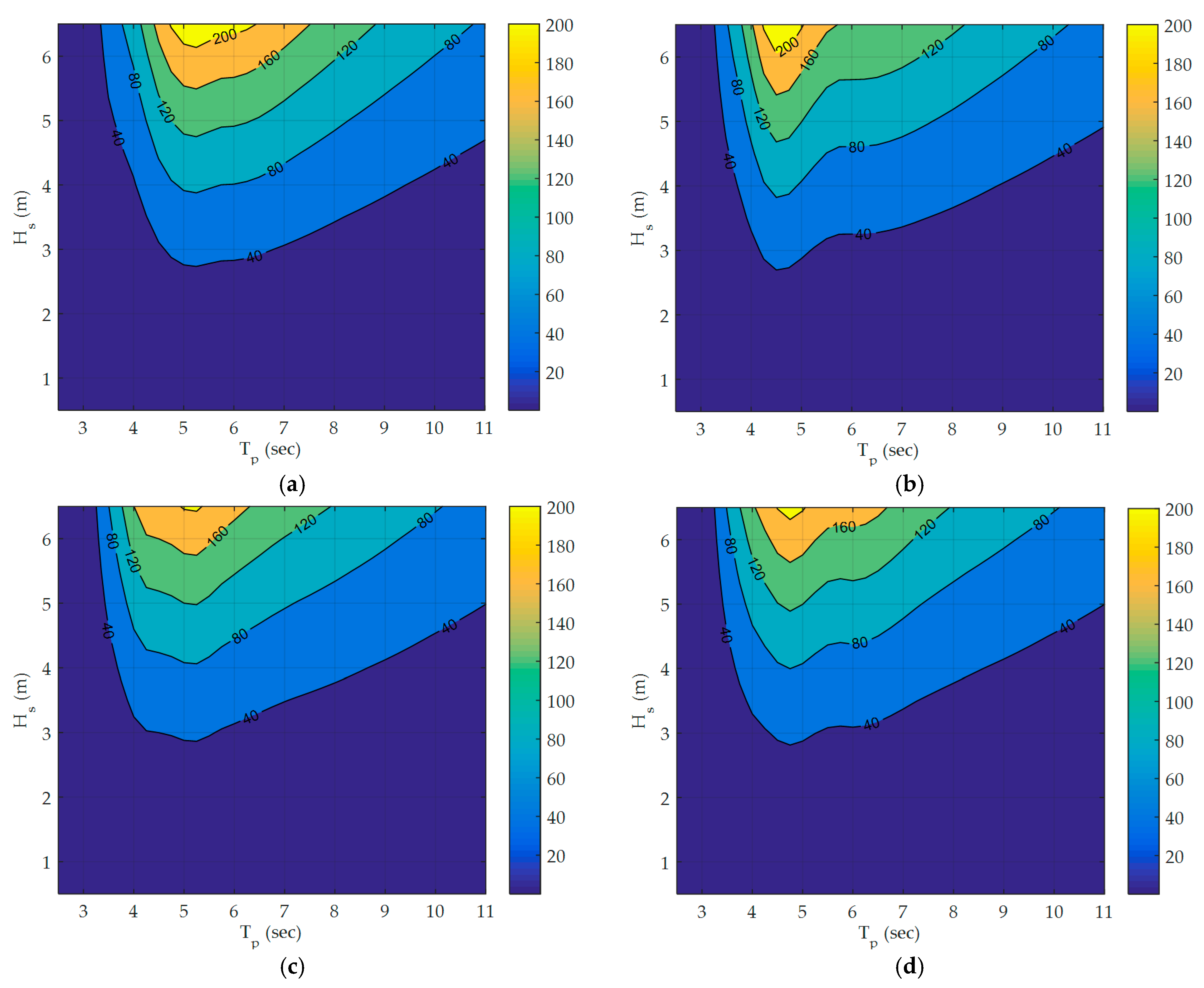
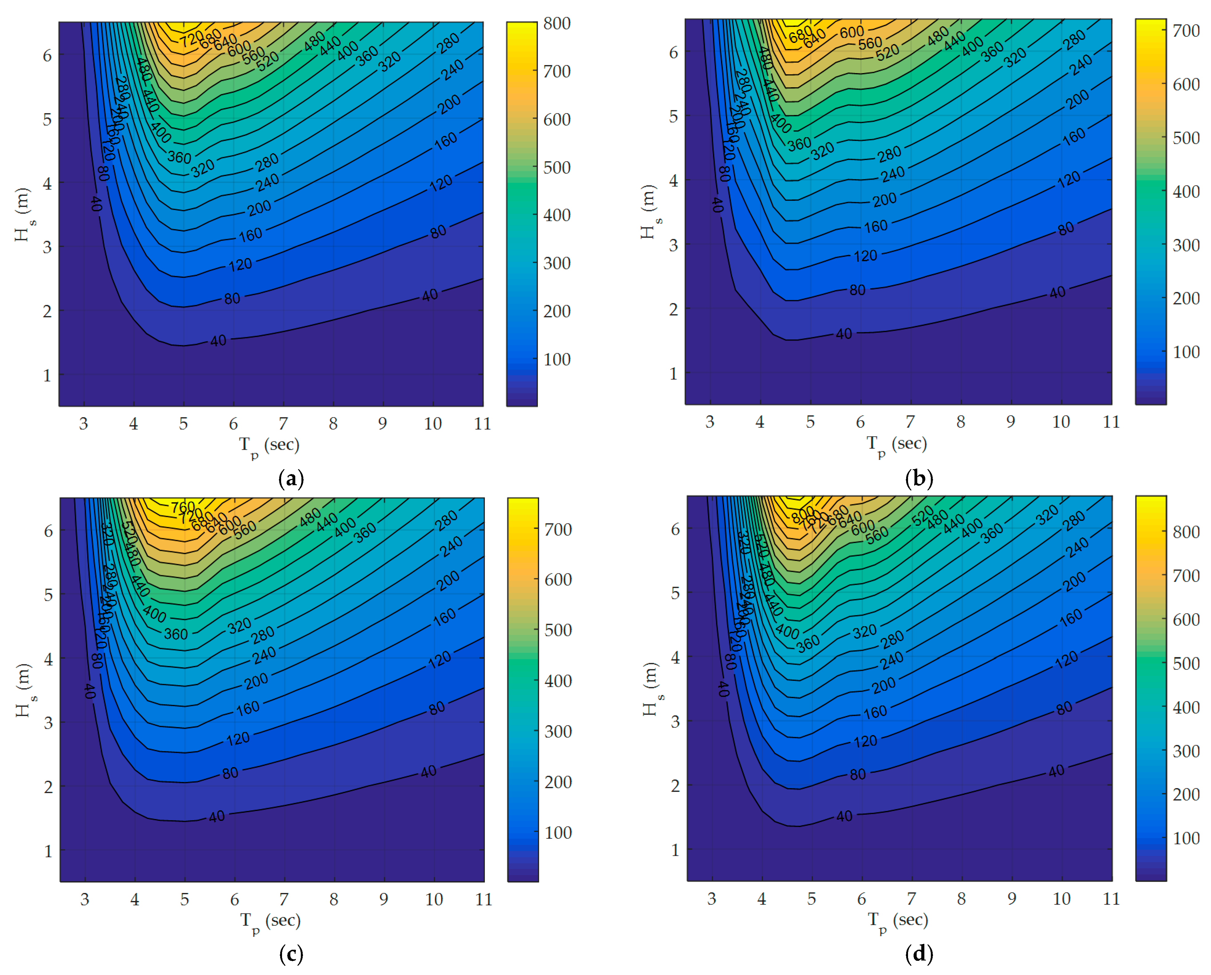
In Figure 10, Figure 11, Figure 12 and Figure 13 we can see the produced wave power (kW) contours (power matrix) for irregular waves, Pirr, of WindWEC for CF1, CF2, CF3 and CF4 examined configurations, respectively, for all the examined values of the distance between the spar and the WECs. For the calculation of the Pirr Equation (16) has been used and applied. It is noted that no control has been used for the damping BPTO of the PTO and a constant damping has been selected equal with the radiation damping of the WEC for its natural period in heave degree of freedom. Based on relevant hydrodynamic analysis the heave radiation damping that corresponds to Tn3 = 4.25 s is used. As it is expected the increase of the number of the WECs results to the increase of the produced power of the combined concept for similar irregular wave conditions. For both CF3 and CF4 examined configurations WindWEC produces power for mild wave conditions. The value of the distance between the spar and WECs plays a dominating factor for the power matrices. For each of the CF1 and CF2, the examined case with D = 20 m results to the larger produced power while for each of the CF3 and CF4 the examined case with D = 40 m has the better performance in terms of produced power for different examined irregular wave cases. The increase of the number of the bodies, and consequently the increase of the hydrodynamic interaction between the different bodies, results to the decrease of the produced power if the distance between the spar and the different bodies remains the same. For the case that a large number of WECs are utilized the distance between the spar and WECs should increase in order the interaction effects not to have negative impact on the produced power.
In order to compare the produced power of the different examined configurations of WindWEC in real sea conditions, the annual-averaged produced wave power, Pannual, (Equation (18)) for two sea states is calculated and presented. The first examined site (Site 1) is presented in [30] and is based on Danish Hydraulic Institute (DHI) MetOcean data portal for the case of a Danish small island in the Baltic Sea while the second one (Site 2) corresponds to the National Wave Energy Test site located off the Annagh Head west of Belmullet [31]. It is stated that the wave climate at a specific site is defined by a set of sea states, defined by their significant wave height, Hs, and peak period, Tp, values, and the probability of occurrence p(Hs,Tp) in one year period. For the examined sites the wave climate matrices are presented in Table 4 and Table 5 below. In Table 6 the annual averaged produced power, Pannual, in kWh/year for all examined configurations and two examined sites are presented. In the same Table it is also presented the value Pannual/number of WECs in kWh/year. For the case that one and two WECs are utilized the largest annual produced power corresponds for D value equals to 20 m, while, for the case that three and four WECs are used the D value that corresponds to the largest annual produced power corresponds to 40 m. The largest produced power is presented for the CF4 configuration with D = 40 m and equals to 191,260 kWh for Site1 and 653,340 kWh for Site2.
5. Conclusions
In the present paper the hydrodynamic response and the prediction of the produced power of different possible configurations of the updated WindWEC concept based on generalized modes analysis is presented for regular and irregular waves. Updated WindWEC consists of a spar and one, two, three or four heaving type WEC buoys. Initially the development of the generalized modes numerical model is presented. With the use of the developed numerical model the effects of structural design parameters on the hydrodynamic response and produced wave power are examined. The structural design parameters are the center-to-center distance of the WECs and spar platform, the number of the WECs and the grid configuration of spar and WECs. Numerical analysis is made in frequency domain and power matrices of the updated WindWEC concept are presented for all examined configurations with different number of WECs. Moreover, the annual produced power of the updated WindWEC in two sites is estimated and presented.
Based on the results the main findings can be summarized in this paragraph. The decrease of the distance between the different bodies results to the decrease of the produced power due to strong hydrodynamic interaction effects. The value of natural period of WEC dominates both the hydrodynamic response and produced power. The combined concept with larger number of WECs in use results to increase of produced power in wider number of wave characteristics; in this case the WECs should be placed in large distance from the central spar body. Hydroelastic analysis can be used efficiently when dealing with combined structures for early-stage assessment of the hydrodynamic response and produced power of WECs. The updated WindWEC can be used in sea sites with different environmental characteristics while extracting valuable amount of wave power.
Moreover, and based on the findings it can be concluded that, the effect of the center-to-center distance between the spar and WECs is large on the hydrodynamic response of, mainly, the WECs for all the examined configurations of updated WindWEC. For the smaller examined value of center-to-center distance, intense hydrodynamic interaction effects exist but are not resulting to the larger produced wave power of updated WindWEC. It is very critical the assessment of the effects of the center-to-center distance on the power performance of the combined concepts.
Large interaction effects exist not only for the diagonal coefficients of added mass and radiation damping matrices but also for the nondiagonal coefficients. Those coefficients should be accounted and used when dealing with the analysis of combined energy concepts consisting of different floating bodies.
The effect of the grid configuration, and consequently of the number of the spar and WECs bodies, is large on the hydrodynamic response for all the examined center-to-center distance values. As the number of the bodies increases the interaction effects are larger.
Irrespectively of the examined center-to-center distance value and grid configuration, the interaction effects on the motions of the WECs are large close to the heave natural period value of WECs, while the interaction effects on the motions of spar platform are insignificant for all examined cases.
With regards to the total produced power of updated WindWEC, CF4 results to the larger maximum total produced power as well as to a wider produced power curve. The smaller examined center-to-center distance value results to the small, produced wave power for all examined configurations attributed to the strong hydrodynamic interaction effects. For the case that a large number of WECs are utilized the distance between the spar and WECs should increase in order the interaction effects not to have negative impact on the produced power.
The generalized modes analysis that is presented in this paper is generic and can be used for the early-stage assessment of combined energy concepts.
The updated WindWEC can be used in sea sites with different environmental characteristics while extracting valuable amount of wave power.
Different possible future studies may arise from this paper related to the WindWEC combined concept; the design of the mooring line system and the design of the arm of the WindWEC for the CF4 configuration is prioritized in relevant fully coupled time domain analysis models. Moreover, the shape optimization of the WEC of the WindWEC for maximizing the produced wave power is also prioritized as a future study.
Author Contributions
The author has read and agreed to the published version of the manuscript.
Acknowledgments
The author would like to acknowledge the “CUT Open Access Author Fund” for covering the open access publication fees of the paper.
Conflicts of Interest
The author declares no conflict of interest.
References
- European Wind Energy Association. Offshore Wind in Europe Key Trends and Statistics 2019; Wind Europe: Brussels, Belgium, 2020. [Google Scholar]
- Hywind Scotland. Available online: https://en.wikipedia.org/wiki/Hywind_Scotland (accessed on 25 May 2020).
- Falcao, A. Wave energy utilization: A review of the technologies. Renew. Sustain. Energy Rev. 2010, 14, 899–918. [Google Scholar] [CrossRef]
- Falnes, J. A review of wave-energy extraction. Mar. Struct. 2007, 20, 185–201. [Google Scholar] [CrossRef]
- Michele, S.; Buriani, F.; Renzi, E.; van Rooij, M.; Jayawardhana, B.; Vakis, A.I. Wave Energy Extraction by Flexible Floaters. Energies 2020, 13, 6167. [Google Scholar] [CrossRef]
- Wave Star Energy. Available online: http://wavestarenergy.com (accessed on 25 May 2020).
- Hansen, R.H.; Kramer, M.M.; Vidal, E. Discrete Displacement Hydraulic Power Take-Off System for the Wavestar Wave Energy Converter. Energies 2013, 6, 4001–4044. [Google Scholar] [CrossRef]
- TROPOS. Available online: http://www.troposplatform.eu/ (accessed on 25 May 2020).
- Marina Platform. Available online: https://www.msp-platform.eu/projects/marina-platform (accessed on 25 May 2020).
- Lavidas, G.; Venugopal, V. Energy Production Benefits by Wind and Wave Energies for the Autonomous System of Crete. Energies 2018, 11, 2741. [Google Scholar] [CrossRef] [Green Version]
- Pham, T.D.; Shin, H. A New Conceptual Design and Dynamic Analysis of a Spar-Type Offshore Wind Turbine Combined with a Moonpool. Energies 2019, 12, 3737. [Google Scholar] [CrossRef] [Green Version]
- Soulard, T.; Babarit, A.; Borgarino, B.; Wyns, M.; Harismendy, M. C-HYP: A combined wave and wind energy platform with balanced contributions. In Proceedings of the 32nd International Conference on Ocean, Offshore and Arctic Engineering, Nantes, France, 4–9 June 2013. [Google Scholar]
- Aubult, A.; Alves, M.; Sarmento, A.; Roddier, D.; Peiffer, A. Modeling of an oscillating water column on the floating foundation WindFloat. In Proceedings of the 30th International Conference on Ocean, Offshore and Arctic Engineering, Rotterdam, The Netherland, 19–24 June 2011. [Google Scholar]
- Muliawan, M.J.; Karimirad, M.; Moan, T. Dynamic response and power performance of a combined spar-type floating wind turbine and coaxial floating wave energy converter. Renew. Energy 2013, 50, 47–57. [Google Scholar] [CrossRef]
- Michailides, C.; Gao, Z.; Moan, T. Experimental study of the functionality of a semisubmersible wind turbine combined with flap-type Wave Energy Converters. Renew. Energy 2016, 93, 675–690. [Google Scholar] [CrossRef]
- Wang, Y.; Zhang, L.; Michailides, C.; Wan, L.; Shi, W. Hydrodynamic Response of a Combined Wind–Wave Marine Energy Structure. J. Mar. Sci. Eng. 2020, 8, 253. [Google Scholar] [CrossRef] [Green Version]
- Gao, Z.; Moan, T.; Wan, L.; Michailides, C. Comparative numerical and experimental study of two combined wind and wave energy concepts. J. Ocean Eng. Sci. 2016, 1, 36–51. [Google Scholar] [CrossRef] [Green Version]
- Ren, N.X.; Zhu, Y.; Ma, Z.; Wu, H.B. Comparative study of hydrodynamic responses of two combined wind turbine and wave energy converter systems under typical operational sea cases. In Proceedings of the 37th International Conference on Ocean, Offshore and Arctic Engineering (OMAE), Madrid, Spain, 17–22 June 2018. [Google Scholar]
- Karimirad, M.; Koushan, K. WindWEC: Combining Wind and Wave Energy Inspired by Hywind and Wavestar. In Proceedings of the International Conference on Renewable Energy Research and Applications, Birmingham, UK, 20–23 November 2016. [Google Scholar]
- Newman, J.N. Wave Effects on Deformable Bodies. Appl. Ocean Res. 1994, 6, 47–59. [Google Scholar] [CrossRef]
- Riggs, H.R.; Ertekin, R.C.; Mills, T.R.J. A Comparative study of RMFC and FEA models for the wave-induced response of a MOB. Mar. Struct. 2000, 13, 217–232. [Google Scholar] [CrossRef]
- Fu, S.; Moan, T.; Chen, X.; Cui, W. Hydroelastic Analysis of Flexible Floating Interconnected Structures. Ocean Eng. 2007, 34, 1516–1531. [Google Scholar] [CrossRef]
- Fu, S.; Weicheng, C.; Chen, X.; Cong, W. Hydroelastic analysis of a nonlinearly connected floating bridge subjected to moving loads. Mar. Struct. 2005, 18, 85–107. [Google Scholar]
- Karimirad, M.; Michailides, C.; Nematbakhsh, A. Offshore Mechanics: Structural and Fluid Dynamics for Recent Applications, 1st ed.; John Wiley & Sons, Inc.: Hoboken, NJ, USA, 2018. [Google Scholar]
- Lee, C.H.; Newman, J.N. An Assessment of Hydroelasticity for Very Large Hinged Vessels. J. Fluids Struct. 2000, 14, 957–970. [Google Scholar] [CrossRef]
- Michailides, C.; Loukogeorgaki, E.; Angelides, D.C. Influence of Connectors’ Stiffness on the Performance of Flexible Floating Breakwaters. In Proceedings of the Nineteenth International Offshore and Polar Engineering Conference, Osaka, Japan, 21–26 July 2009; Volume 3, pp. 1094–1101. [Google Scholar]
- Lee, C.H.; Zhu, X. Application of Hyper-Singular Integral Equations for a Simplified Model of Viscous Dissipation. In Proceedings of the 28th International Ocean and Polar Engineering Conference, Sapporo, Japan, 10–15 June 2018. [Google Scholar]
- Falnes, J. Wave-energy conversion through relative motion between two single-mode oscillating bodies. J. Offshore Mech. Arct. Eng. 1999, 121, 32–38. [Google Scholar] [CrossRef]
- Falnes, J. Ocean Waves and Oscillating Systems: Linear Interactions Including Wave-Energy Extraction, 1st ed.; Cambridge University Press: Cambridge, UK, 2002; pp. 17–20. [Google Scholar]
- Margheritini, L.; Kofoed, J.P. Weptos Wave Energy Converters to Cover the Energy Needs of a Small Island. Energies 2019, 12, 423. [Google Scholar] [CrossRef] [Green Version]
- Cahill, B.G.; Lewis, T. Weptos Wave energy resource characterisation of the Atlantic Marine Energy Test Site. Int. J. Mar. Energy 2013, 1, 3–15. [Google Scholar] [CrossRef]
Figure 1.
WindWEC combined concept as originally proposed.

Figure 2.
(a) CF1 examined configuration of WindWEC, (b) CF2 examined configuration of WindWEC, (c) CF3 examined configuration of WindWEC and (d) CF4 examined configuration of WindWEC.
Figure 2.
(a) CF1 examined configuration of WindWEC, (b) CF2 examined configuration of WindWEC, (c) CF3 examined configuration of WindWEC and (d) CF4 examined configuration of WindWEC.

Figure 3.
Heave added mass coefficients for the: (a) WEC1 of CF1 and CF2, (b) WEC1 of CF3 and CF4, (c) WEC2 of CF3 and CF4 and (d) WEC3 of CF2 and CF4.
Figure 3.
Heave added mass coefficients for the: (a) WEC1 of CF1 and CF2, (b) WEC1 of CF3 and CF4, (c) WEC2 of CF3 and CF4 and (d) WEC3 of CF2 and CF4.

Figure 4.
(a) A33 of spar for CF1 and CF4, (b) A55 of spar for CF1 and CF4, (c) A88 of WEC1 for CF1 and CF4 and (d) A73 of WEC1 for CF1 and CF4.
Figure 4.
(a) A33 of spar for CF1 and CF4, (b) A55 of spar for CF1 and CF4, (c) A88 of WEC1 for CF1 and CF4 and (d) A73 of WEC1 for CF1 and CF4.

Figure 5.
Radiation damping coefficients for: (a) WEC1 of CF1 and CF2, (b) WEC1 of CF3 and CF4, (c) WEC3 of CF2 and CF4, and (d) B88 coefficient for WEC1 of CF1 and CF4 configurations.
Figure 5.
Radiation damping coefficients for: (a) WEC1 of CF1 and CF2, (b) WEC1 of CF3 and CF4, (c) WEC3 of CF2 and CF4, and (d) B88 coefficient for WEC1 of CF1 and CF4 configurations.

Figure 6.
Heave excitation loads of WECs and spar for: (a) WEC1 of CF1 and CF2, (b) WEC1 of CF3 and CF4, (c) WEC3 of CF2 and CF4, and (d) spar of CF1 and CF4.
Figure 6.
Heave excitation loads of WECs and spar for: (a) WEC1 of CF1 and CF2, (b) WEC1 of CF3 and CF4, (c) WEC3 of CF2 and CF4, and (d) spar of CF1 and CF4.

Figure 7.
Heave RAOs of WECs, for: (a) WEC1 of CF1 and CF2, (b) WEC1 of CF3 and CF4, (c) WEC3 of CF2 and CF4, (d) WEC1, WEC2, WEC3 and WEC4 of CF4 and (e) spar of CF1 and CF4.
Figure 7.
Heave RAOs of WECs, for: (a) WEC1 of CF1 and CF2, (b) WEC1 of CF3 and CF4, (c) WEC3 of CF2 and CF4, (d) WEC1, WEC2, WEC3 and WEC4 of CF4 and (e) spar of CF1 and CF4.

Figure 8.
Produced wave power Ptot of WindWEC for: (a) CF1 and all D examined values, (b) CF2 and all D examined values, (c) CF3 and all D examined values, and (d) CF4 and all D examined values.
Figure 8.
Produced wave power Ptot of WindWEC for: (a) CF1 and all D examined values, (b) CF2 and all D examined values, (c) CF3 and all D examined values, and (d) CF4 and all D examined values.

Figure 9.
(a) Produced wave power Ptot of WindWEC for CF1, CF2 CF3 and CF4 for D = 20 m and (b) PWECk of WECs of CF4 configuration and D = 20 m.
Figure 9.
(a) Produced wave power Ptot of WindWEC for CF1, CF2 CF3 and CF4 for D = 20 m and (b) PWECk of WECs of CF4 configuration and D = 20 m.

Figure 10.
Produced wave power Pirr contour of WindWEC for CF1 examined configuration and: (a) D = 10 m, (b) D = 20 m, (c) D = 30 m and (d) D = 40 m.
Figure 10.
Produced wave power Pirr contour of WindWEC for CF1 examined configuration and: (a) D = 10 m, (b) D = 20 m, (c) D = 30 m and (d) D = 40 m.

Figure 11.
Produced wave power Pirr contour of WindWEC for CF2 examined configuration and: (a) D = 10 m, (b) D = 20 m, (c) D = 30 m and (d) D = 40 m.
Figure 11.
Produced wave power Pirr contour of WindWEC for CF2 examined configuration and: (a) D = 10 m, (b) D = 20 m, (c) D = 30 m and (d) D = 40 m.

Figure 12.
Produced wave power Pirr contour of WindWEC for CF3 examined configuration and: (a) D = 10 m, (b) D = 20 m, (c) D = 30 m and (d) D = 40 m.
Figure 12.
Produced wave power Pirr contour of WindWEC for CF3 examined configuration and: (a) D = 10 m, (b) D = 20 m, (c) D = 30 m and (d) D = 40 m.

Figure 13.
Produced wave power Pirr contour of WindWEC for CF4 examined configuration and: (a) D = 10 m, (b) D = 20 m, (c) D = 30 m and (d) D = 40 m.
Figure 13.
Produced wave power Pirr contour of WindWEC for CF4 examined configuration and: (a) D = 10 m, (b) D = 20 m, (c) D = 30 m and (d) D = 40 m.


Table 1.
Characteristics of different components of the WindWEC [19].
Table 1.
Characteristics of different components of the WindWEC [19].
| Spar | WEC | ||
|---|---|---|---|
| Displacement | 8016 m3 | Diameter | 10 m |
| Diameter (free surface) | 6.5 m | Draft | 3 m |
| Diameter (bottom) | 9.4 m | Conic length | 1 m |
| Entire mass | 8216 × 103 kg | Entire mass of WEC | 180 × 103 kg |
| Center of gravity | −78.5 m | Center of gravity | −1.5 m |
| Center of buoyancy | −62.0 m | Center of buoyancy | −1.17 m |
| Mass moment of inertia, IXX | 69.84 × 10⁹ kg·m2 | Mass moment of inertia, IXX | 1.690 × 10⁶ kg·m2 |
| Mass moment of inertia, IZZ | 16.78 × 10⁷ kg·m2 | Mass moment of inertia, IZZ | 3.018 × 10⁶ kg·m2 |
Table 2.
Examined configurations of the WindWEC.
| WindWEC Configuration | Utilized WECs | Total Degrees of Freedom, N |
|---|---|---|
| CF1 | WEC1 | 8 |
| CF2 | WEC1 and WEC3 | 10 |
| CF3 | WEC1, WEC2 and WEC3 | 12 |
| CF4 | WEC1, WEC2, WEC3 and WEC4 | 14 |
Table 3.
Natural periods of heave, Tn3, and pitch, Tn5, motions of spar and WEC.
| Examined Body | Heave (sec) | Pitch (sec) |
|---|---|---|
| Spar | 20.50 | 30.50 |
| WEC | 4.25 | 4.00 |
Table 4.
Wave climate matrix of the examined Site1.
| Tp (sec) | Total (%) | ||||||||||||
|---|---|---|---|---|---|---|---|---|---|---|---|---|---|
| 1.5 | 2.5 | 3.5 | 4.5 | 5.5 | 6.5 | 7.5 | 8.5 | 9.5 | 10.5 | 11.5 | |||
| Hs (m) | 0.25 | 0.02277 | 3.21038 | 12.3179 | 7.57058 | 2.9827 | 1.10428 | 0.13661 | 0 | 0.01138 | 0.01138 | 0 | 27.3679 |
| 0.75 | 0 | 0 | 4.61066 | 15.255 | 7.82104 | 2.4704 | 1.1612 | 0.67168 | 0.3643 | 0.04554 | 0 | 32.3998 | |
| 1.25 | 0 | 0 | 0 | 1.54827 | 12.2154 | 3.9276 | 1.03597 | 0.43261 | 0.148 | 0 | 0 | 19.3078 | |
| 1.75 | 0 | 0 | 0 | 0 | 1.5255 | 7.61612 | 0.9449 | 0.43261 | 0.07969 | 0.05692 | 0 | 10.6557 | |
| 2.25 | 0 | 0 | 0 | 0 | 0 | 2.43625 | 3.44945 | 0.50091 | 0 | 0.01138 | 0.02277 | 6.42077 | |
| 2.75 | 0 | 0 | 0 | 0 | 0 | 0.18215 | 1.42304 | 0.80829 | 0 | 0.03415 | 0.01138 | 2.45902 | |
| 3.25 | 0 | 0 | 0 | 0 | 0 | 0 | 0.10246 | 0.5123 | 0.13661 | 0.02277 | 0 | 0.77414 | |
| 3.75 | 0 | 0 | 0 | 0 | 0 | 0 | 0 | 0.05692 | 0.17077 | 0 | 0 | 0.22769 | |
| 4.25 | 0 | 0 | 0 | 0 | 0 | 0 | 0 | 0.02277 | 0.13661 | 0.04554 | 0 | 0.20492 | |
| 4.75 | 0 | 0 | 0 | 0 | 0 | 0 | 0 | 0 | 0.01138 | 0.17077 | 0 | 0.18215 | |
| Total (%) | 0.02277 | 3.21038 | 16.9285 | 24.3739 | 24.5446 | 17.7368 | 8.25364 | 3.43807 | 1.05874 | 0.39845 | 0.03415 | 100 | |
Table 5.
Wave climate matrix of the examined Site2.
| Te (sec) | Total (%) | |||||||||||
|---|---|---|---|---|---|---|---|---|---|---|---|---|
| 5.5 | 6.5 | 7.5 | 8.5 | 9.5 | 10.5 | 11.5 | 12.5 | 13.5 | 14.5 | |||
| Hs (m) | 0.25 | 0.1 | 0.5 | 0.6 | 0.1 | 0 | 0 | 0 | 0 | 0 | 0 | 1.3 |
| 0.75 | 0.8 | 2.8 | 4.4 | 2.3 | 0.7 | 0 | 0 | 0 | 0 | 0 | 11 | |
| 1.25 | 0.8 | 3.8 | 4.8 | 4.5 | 2.4 | 0.5 | 0 | 0 | 0 | 0 | 16.8 | |
| 1.75 | 0.1 | 2.8 | 3.7 | 3 | 3.3 | 1.4 | 0.3 | 0 | 0 | 0 | 14.6 | |
| 2.25 | 0 | 0.7 | 3.4 | 3 | 2.5 | 1.8 | 0.6 | 0.1 | 0 | 0 | 12.1 | |
| 2.75 | 0 | 0.1 | 1.6 | 2.8 | 2 | 1.8 | 0.9 | 0.1 | 0 | 0 | 9.3 | |
| 3.25 | 0 | 0 | 0.4 | 2.1 | 1.7 | 1.5 | 1.2 | 0.5 | 0.1 | 0 | 7.5 | |
| 3.75 | 0 | 0 | 0.1 | 1.4 | 1.9 | 1.4 | 1 | 0.5 | 0.2 | 0 | 6.5 | |
| 4.25 | 0 | 0 | 0 | 0.4 | 1.5 | 1.4 | 1 | 0.5 | 0.3 | 0 | 5.1 | |
| 4.75 | 0 | 0 | 0 | 0.1 | 0.9 | 1.3 | 0.9 | 0.4 | 0.2 | 0.1 | 3.9 | |
| 5.25 | 0 | 0 | 0 | 0 | 0.3 | 1.1 | 0.9 | 0.5 | 0.2 | 0.1 | 3.1 | |
| 5.75 | 0 | 0 | 0 | 0 | 0.2 | 0.7 | 0.6 | 0.5 | 0.2 | 0.1 | 2.3 | |
| 6.25 | 0 | 0 | 0 | 0 | 0 | 0.4 | 0.5 | 0.4 | 0.2 | 0.1 | 1.6 | |
| 6.75 | 0 | 0 | 0 | 0 | 0 | 0.2 | 0.4 | 0.3 | 0.2 | 0.1 | 1.2 | |
| 7.25 | 0 | 0 | 0 | 0 | 0 | 0.1 | 0.3 | 0.4 | 0.2 | 0.1 | 1.1 | |
| 7.75 | 0 | 0 | 0 | 0 | 0 | 0 | 0.2 | 0.2 | 0.2 | 0.1 | 0.7 | |
| 8.25 | 0 | 0 | 0 | 0 | 0 | 0 | 0.1 | 0.2 | 0.2 | 0.1 | 0.6 | |
| 8.75 | 0 | 0 | 0 | 0 | 0 | 0 | 0 | 0.1 | 0.1 | 0 | 0.2 | |
| 9.25 | 0 | 0 | 0 | 0 | 0 | 0 | 0 | 0.1 | 0.1 | 0.1 | 0.3 | |
| 9.75 | 0 | 0 | 0 | 0 | 0 | 0 | 0 | 0 | 0.2 | 0.1 | 0.3 | |
| 10.25 | 0 | 0 | 0 | 0 | 0 | 0 | 0 | 0 | 0 | 0.1 | 0.1 | |
| Total (%) | 1.8 | 10.7 | 19 | 19.7 | 17.4 | 13.6 | 8.9 | 4.8 | 2.6 | 1.1 | 99.6 | |
Table 6.
Annual averaged produced power, Pannual, for all examined configurations and two examined sites.
Table 6.
Annual averaged produced power, Pannual, for all examined configurations and two examined sites.
| WindWEC Configuration | Pannual (kWh per Year) | Pannual/Number of WECs (kWh per Year) | Pannual (kWh per Year) | Pannual/Number of WECs (kWh per Year) |
|---|---|---|---|---|
| Site1 | Site2 | |||
| CF1 10 m | 46,576 | 46,576 | 167,420 | 167,420 |
| CF1 20 m | 54,437 | 54,437 | 176,150 | 176,150 |
| CF1 30 m | 46,050 | 46,050 | 161,620 | 161,620 |
| CF1 40 m | 46,674 | 46,674 | 161,520 | 161,520 |
| CF2 10 m | 91,739 | 45,870 | 328,790 | 164,395 |
| CF220 | 94,684 | 47,342 | 341,230 | 170,615 |
| CF2 30 m | 90,014 | 45,007 | 321,230 | 160,615 |
| CF2 40 m | 91,957 | 45,979 | 322,800 | 161,400 |
| CF3 10 m | 136,190 | 45,397 | 490,990 | 163,663 |
| CF3 20 m | 134,020 | 44,673 | 483,820 | 161,273 |
| CF3 30 m | 137,440 | 45,813 | 483,080 | 161,027 |
| CF3 40 m | 140,690 | 46,897 | 492,960 | 164,320 |
| CF4 10 m | 186,000 | 46,500 | 650,520 | 162,630 |
| CF4 20 m | 177,100 | 44,275 | 640,620 | 160,155 |
| CF4 30 m | 185,560 | 46,390 | 646,110 | 161,528 |
| CF4 40 m | 191,260 | 47,815 | 653,340 | 163,335 |
Publisher’s Note: MDPI stays neutral with regard to jurisdictional claims in published maps and institutional affiliations. |
© 2021 by the author. Licensee MDPI, Basel, Switzerland. This article is an open access article distributed under the terms and conditions of the Creative Commons Attribution (CC BY) license (http://creativecommons.org/licenses/by/4.0/).
Share and Cite
MDPI and ACS Style
Michailides, C. Ηydrodynamic Response and Produced Power of a Combined Structure Consisting of a Spar and Heaving Type Wave Energy Converters. Energies 2021, 14, 225. https://0-doi-org.brum.beds.ac.uk/10.3390/en14010225
AMA Style
Michailides C. Ηydrodynamic Response and Produced Power of a Combined Structure Consisting of a Spar and Heaving Type Wave Energy Converters. Energies. 2021; 14(1):225. https://0-doi-org.brum.beds.ac.uk/10.3390/en14010225
Chicago/Turabian StyleMichailides, Constantine. 2021. "Ηydrodynamic Response and Produced Power of a Combined Structure Consisting of a Spar and Heaving Type Wave Energy Converters" Energies 14, no. 1: 225. https://0-doi-org.brum.beds.ac.uk/10.3390/en14010225
Note that from the first issue of 2016, this journal uses article numbers instead of page numbers. See further details here.