A Novel Co-Phase Power-Supply System Based on Modular Multilevel Converter for High-Speed Railway AT Traction Power-Supply System


Institute of Traction Power Supply, School of Electrical Engineering, Beijing Jiaotong University, Beijing 100044, China
*
Author to whom correspondence should be addressed.
Energies 2021, 14(1), 253; https://0-doi-org.brum.beds.ac.uk/10.3390/en14010253
Submission received: 21 November 2020
/
Revised: 24 December 2020
/
Accepted: 25 December 2020
/
Published: 5 January 2021
(This article belongs to the Special Issue Power Quality in Electrified Transportation Systems)
Abstract
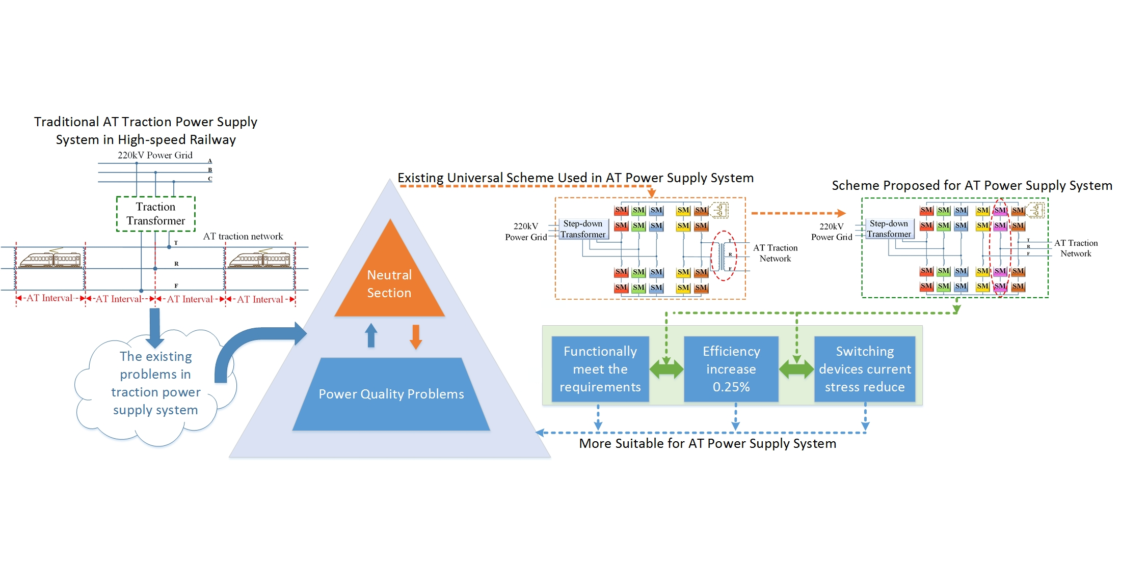
:The existing problems of the traction power-supply system (i.e., the existence of the neutral section and the power quality problems) limit the development of railways, especially high-speed railways, which are developing rapidly worldwide. The existence of the neutral section leads to the speed loss and traction loss as well as mechanical failures, all of which threaten the fast and safe operation of the train and the system. Meanwhile, the power quality problems (e.g., the negative sequence current, the reactive power, and the harmonic) can bring a series of problems that cannot be ignored on the three-phase grid side. In response, many researchers have proposed co-phase power-supply schemes to solve these two problems simultaneously. Given that the auto-transformer (AT) power-supply mode has become the main power-supply mode for the high-speed railway traction power-supply system, it has a bright future following the rapid development of the high-speed railway. In addition, there is no co-phase power-supply scheme designed for AT power-supply mode in the existing schemes. Therefore, the main contribution of this paper is to propose a specifically designed power-supply mode more suitable for the AT, as well as to establish the control systems for the rectifier side and the inverter side. In addition, for the proposed scheme, the operation principle is analyzed, the mathematical model is built, and the control system is created, and its functionality is verified by simulation, and its advantages are compared and summarized finally. The result proves that it can meet functional requirements. At the same time, compared with the existing co-phase power-supply scheme, it saves an auto-transformer in terms of topology, reduces the current stress by in terms of the current stress of the switching device, and reduces the power loss by in terms of the entire system power loss, which will result in a larger amount of electricity being saved. All of this makes it a more suitable co-phase power-supply scheme for the AT power-supply mode.

1. Introduction
There are still two significant problems in the current railway traction power-supply system:
- (1)
- Neutral Section:
Due to the single-phase, non-linear, random fluctuating load characteristics of the locomotive, the railway traction power-supply system adopts the rotating phase sequence method to supply power to the locomotive (i.e., the phase of the traction network will change every 20 km–25 km). Therefore, the areas of different phase sequences need to be isolated, which leads to the existence of a non-electrical zone, which is the neutral section [1].
The neutral section results in the loss of the speed and the traction of the train as well as the mechanical wear and tear in traction power-supply systems and locomotives. In addition, there already have some cases of train ramp accidents and substation tripping accidents due to the neutral section. Thus, it really brings major safety hazards to the fast and safe operation of the train and system. In particular, high-speed railways will pass through the neutral section more frequently because of their high speed. For the development of railways, especially high-speed railways, it is necessary to solve the problem of the neutral section [2].
In response to the problems brought by the neutral section, researchers have proposed many schemes. Recently, more attention has been paid to the continuous power passing through neutral section scheme. e.g., mechanical switches ground auto-passing neutral section scheme [3], electronic switches ground auto-passing neutral section scheme [4,5], flexible ground auto-passing neutral section scheme [6]. Although these schemes can solve the power problems brought by the neutral section to some extent, such as reduce the time of power loss and reduce the over-voltage and over-current in the process of passing through the neutral section, they do not fundamentally eliminate the neutral section area on the traction network, so the mechanical weakness is still there, which still cause mechanical losses and economic costs.
- (2)
- Power Quality Problem:
The locomotive loads with non-linear, single-phase, and random fluctuation characteristics bring the power quality problems to the power grid, e.g., the negative sequence current, harmonics, and reactive power.
The power quality problems will pose a hazard to the grid and equipment. Negative sequence currents can be harmful to generators, asynchronous motors, transformers, transmission lines, and communication systems. Harmonics, especially the high-order harmonics brought by the “AC-DC-AC” electric locomotives that have been widely used in high-speed railways and heavy-haul railways in recent years, are prone to cause high-frequency resonance, which can easily cause damage to electrical equipment and accidents. Reactive power can increase the loss of lines and equipment, increase the voltage drop of lines and transformers, and bring adverse effects to the power grid and equipment [7,8,9].
In response to the power quality problems, researchers have proposed many schemes. A passive filter in [10] was used to solve the harmonics and reactive power problems. The Static Var Compensator (SVC) in [11,12] was used to address the negative sequence current and reactive power, while it is quite limited in its ability to suppress harmonics. The Static Synchronous Compensator (STATCOM) in [13] has better harmonic characteristics and can use for negative sequence current, reactive power, and harmonics compensation. The Active Power Filter (APF) in [14] can solve power quality problems effectively, but the cost is relatively high. However, these solutions are only proposed to address power quality issues, but do not attempt to address the problem of the neutral section.
Recently, some researchers have proposed co-phase power-supply schemes to simultaneously solve the neutral section and power quality problems. Among them, one category is the compensation co-phase power-supply scheme, and the other category is the through co-phase power-supply scheme. The compensation co-phase power-supply schemes can solve the power quality problems and the neutral section at the same time. However, it can only eliminate the neutral section at the substation but cannot eliminate the neutral section in the entire traction network. This kind of co-phase power-supply schemes includes China’s first co-phase power-supply unit, which is put into operation at the Mershan substation in 2010 [10] and the first single three-phase combined co-phase power-supply unit at the Shangyu substation in 2014 [15], as well as the Active Power Compensator (APC) [16], the Railway Power Conditioner (PRC) [17,18], the Hybrid Power Quality Conditioner (HPQC) [19,20,21,22], and the Hybrid Electrical Magnetic Power Quality Compensator (HEMPQC) [23]. The through co-phase power-supply schemes can simultaneously and completely solve the power quality problems and eliminate all neutral section of the whole traction network, making the traction network whole line through, e.g., the schemes based on the Cascaded H-Bridge (CHB) converter in [24,25] and the schemes based on the Modular Multilevel Converter (MMC) in [26].
However, these co-phase power-supply schemes are not specifically detailed in terms of the specific power-supply mode. As is well known, high-speed railways are developing rapidly all over the world since they attract great attention from many countries due to their high speed, large transportation capacity, low average energy consumption, light environmental impact, and good economic benefits. To improve the power-supply capacity of the traction network, reduce the number of traction substation and the electromagnetic interference to the adjacent metal conductors, Japan first use the AT power-supply mode in high-speed railways [27].
As for the two prominent problems existing in the railway system. The existence of the neutral section is a common problem in existing electrified railways, and it exists worldwide. At the present stage, there are problems of the neutral section in electrified railways in China, Japan, France, and the United Kingdom. Only Germany built a power grid on the railway with a frequency different from that of the public grid to isolate it from the public grid, achieve the same phase across the entire line, cancel the neutral section, and realize the co-phase power-supply system. Power quality is also a common problem in electrified railways worldwide. The Japanese Shinkansen used STATCOM [28] and RPC [29,30] to solve the power quality problem in 1993 and 2002, respectively. With the rapid development of high-speed railways, the AT power-supply mode has been vigorously promoted and has become the main power-supply mode for high-speed railways [31]. In view of the wide application of AT power-supply mode in high-speed railways and its bright prospects, scheme to these two prominent problems in AT power-supply system are valuable to study.
Therefore, the main contribution and innovation of this paper is that under the background that there is no co-phase power-supply scheme designed for AT power-supply mode, a co-phase power-supply scheme designed for AT power-supply mode and more suitable for it is proposed, and the control systems for the rectifier side and the inverter side is created, and the control section that can make the newly added bridge arm voltage balance is added to the control system of the inverter side. In addition, for this scheme, its operation principle is analyzed, its mathematical model is established, its control system is created, its functionality is verified by simulation, and finally, its superiority over other schemes when applied to the AT power-supply mode is analyzed and summarized. The results prove that the topology proposed in this paper is superior for AT power-supply system in the following aspects, in terms of topology, it eliminates an auto-transformer, in terms of current stress of the insulated gate bipolar transistor (IGBT) of the bridge arm of the inverter, it reduces the current stress by , in terms of power loss, it reduces the power loss of the system by , which means that for a 40 MW traction substation, 100 kWh of power can be saved in one hour, and the long-term power savings of many substations will be significant.
This paper is organized as follows. In Section 2, the operating principle and mathematical model of the proposed scheme are described. In Section 3, the control system is illustrated. In Section 4, the simulation verification and advantages analysis of the proposed topology are elaborated. In Section 6, the conclusion is stated.
2. Operation Principle of the Proposed Co-Phase Power-Supply Scheme
2.1. The Topology of the Proposed Scheme
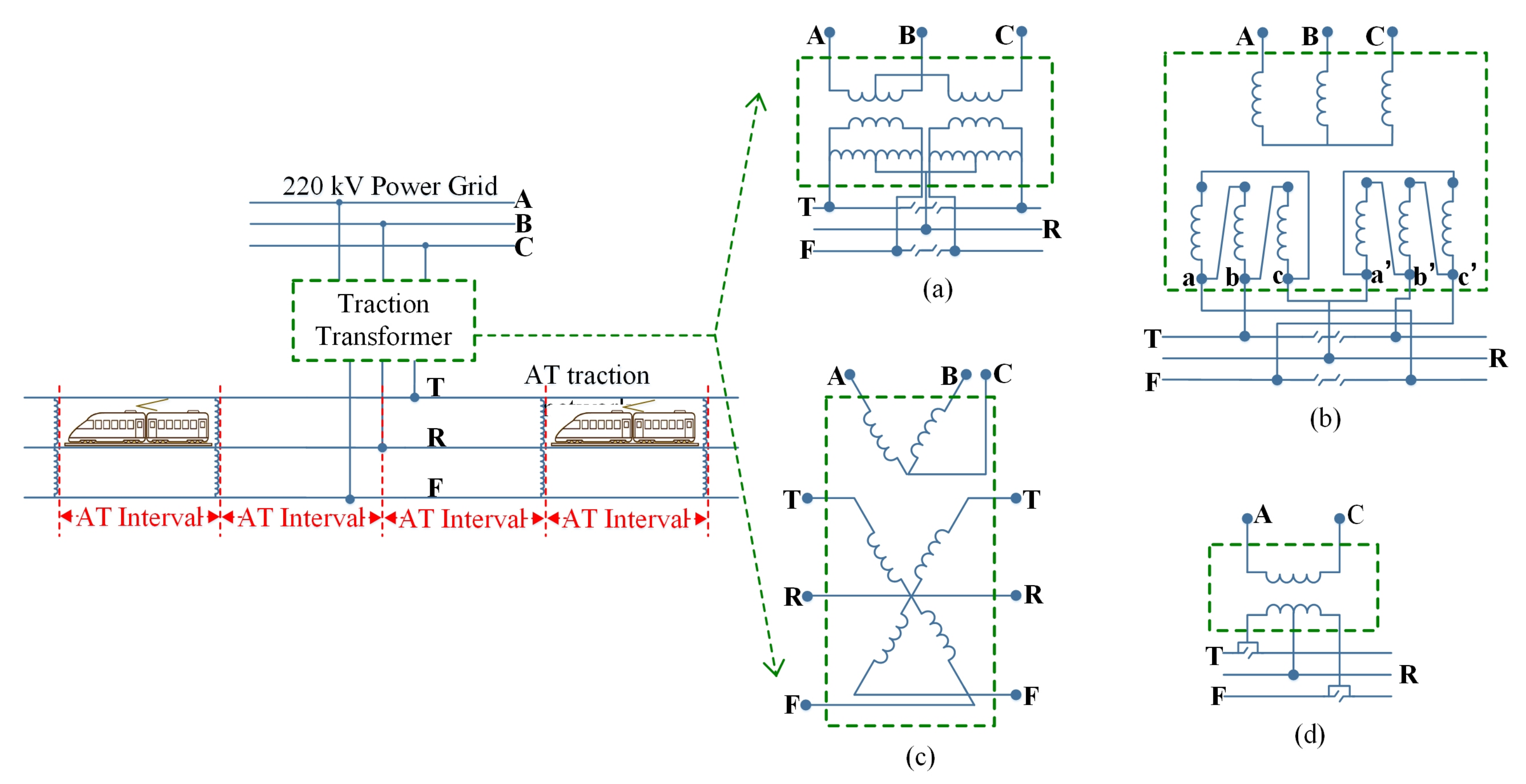
In the existing railway power-supply system, the Auto-Transformer (AT) power-supply mode can not only reduce the interference of the electrified railway to the adjacent communication lines but also has good technical and economic indexes for the traction power-supply system, which make it more suitable to the operation of high-speed and high-power electric locomotives. In terms of structure, as shown in Figure 1, AT power-supply mode is composed of traction transformer, auto-transformer, catenary, steel rail, and positive feeder. The wiring form of traction transformer in AT power-supply mode can be divided into the three-phase–two-phase balanced transformer shown in Figure 1a (taking the most widely used Scott wiring three-phase-two-phase balanced transformer [32] as an example, and adding the required auto-transformer in the substation to the secondary side), the three-phase crossing wiring traction transformer shown in Figure 1b [33], the V/X wiring traction transformer shown in Figure 1c [34], and the secondary midpoint withdrawable single-phase wiring traction transformer shown in Figure 1d [35]. The auto-transformer in the AT power-supply mode is connected in parallel between the contact suspension and the positive feeder, eliminating the segmentation caused by the addition of the transformer to the contact network. The distance between two auto-transformers is generally 8–15 km.
Researchers have proposed several schemes to the existing problems of neutral section and power quality in the system. Among them, the schemes to neutral section can be divided into power-off neutral section passing scheme and live-line neutral section passing scheme according to whether the main circuit breaker is closed or not. The live-line neutral section passing schemes can be divided into column switch neutral section passing scheme, mechanical switch ground automatic neutral section passing scheme, electronic switch ground automatic neutral section passing scheme and flexible ground automatic neutral section passing scheme [36]. The performance of each scheme in terms of functionality, operation, cost and maintenance has been listed in Table 1 below.
It can be seen from the table that in terms of functionality, power loss time and over-voltage, the three ground automatic neutral section passing schemes have a shorter power-loss time, which brings less speed loss, and at the same time, less over-voltage impact. Among them, the best is the flexible ground automatic neutral section passing scheme, which realizes the complete uninterrupted power supply and no over-voltage shock. The other solutions have relatively long power-loss time, relatively large speed loss, and over-voltage impact. Manual power-off neutral section passing scheme is the worst, since the power-loss time is long, and the speed loss is large, and it is easy to cause over-voltage impact. In operation, according to the fatigue degree of the train crew, except for the manual power-off neutral section passing scheme, there is no need for the train crew to operate, which will not cause the passing through the neutral section with electricity caused by human operation errors. In terms of cost and maintenance, the three ground automatic neutral section passing schemes are more expensive to invest in, with the flexible above-ground automatic over-phase being the most expensive. In terms of switch lifetime, the three ground automatic neutral section passing scheme involve switches. The mechanical switch has a short lifetime and high maintenance costs. The switches involved in the electronic switch ground automatic neutral section passing scheme and the flexible ground automatic neutral section passing scheme have a long lifetime and the maintenance cost is not high [4,6,36,37,38].
Those schemes to power quality problems include passive filter, Static Var Compensator (SVC), Static Synchronous Compensator (STATCOM), Active Power Filter (APF), Railway Power Conditioner (RPC). As shown in Table 2, in comparison, passive filters are used to control harmonics and reactive power, but they can only eliminate specific harmonics. In addition, it is easy to resonate with the system impedance and cause harmonic amplification. Since the device cannot follow the dynamic changes in time, the fixed capacitor value in each passive filter cannot totally compensate the frequently change reactive power, then cannot reach a unitary power factor correction [39]. SVC is used for negative sequence and reactive power compensation, but its suppression effect on harmonics is limited, and it will bring harmonic problems by itself. In addition, may produce series and parallel resonance. Compared to the SVC, STATCOM behaves as a bidirectional reactive power compensator, with a faster response time, larger load capability, lower harmonic contents and more compact design structure [39]. APF can eliminate harmonics well, but when APF is used to compensate negative sequence and reactive power, its cost is high, so it is usually used in combination with passive compensation. PRC is a relatively successful power management program, which effectively realizes the comprehensive compensation of reactive power, negative sequence and harmonic current [39,40,41].
Recently, the co-phase power-supply scheme proposed by researchers can simultaneously and well solve the problems of neutral section and power quality. These co-phase power-supply schemes can be divided into compensative co-phase power-supply schemes and continuous co-phase power-supply schemes. Compensative co-phase power-supply schemes include combined co-phase power-supply schemes, APC, RPC, HPQC, etc. Continuous co-phase power-supply schemes include continuous co-phase power-supply schemes based on cascaded H-bridge structure and continuous co-phase power-supply schemes based on modular multilevel converter (MMC). The compensative co-phase power-supply scheme is to combine with the transformer to supply power to the traction network. The negative sequence reactive harmonics are compensated by the installed power electronic devices on the secondary side of the traction transformer, but it can only eliminate the neutral section in the substation. The neutral sections where the districts are located are still there, and the full line continuous cannot be achieved. The continuous co-phase power-supply scheme uses a back-to-back power electronic structure to directly hang to the traction network. The amplitude and phase of the output voltage of this structure can be controlled. It can achieve the same phase of the traction network across the entire line, thereby achieving a full line continuous. At the same time, it can also compensate the negative sequence current, reactive power and harmonics well.
The continuous co-phase power-supply scheme replaces the traction transformer in the traditional traction power-supply system, which connects the three-phase power grid and the traction network with a co-phase power-supply device, which is generally a back-to-back structure consisting of switching devices. By controlling the rectifier side of the back-to-back structure, the power quality problems (i.e., negative sequence current, reactive power, and harmonics) that may be brought to the power grid side can be addressed. At the same time, by controlling the inverter side in the back-to-back structure, the amplitude, phase, and frequency of the output voltage supplied to the traction network are controllable to achieve the same phase of the output voltage of the substations, thereby achieving the same phase of the entire traction network, thereby eliminating the neutral section. Therefore, the through co-phase power supply can wholly and simultaneously solve the problems of the neutral section and power quality problems.
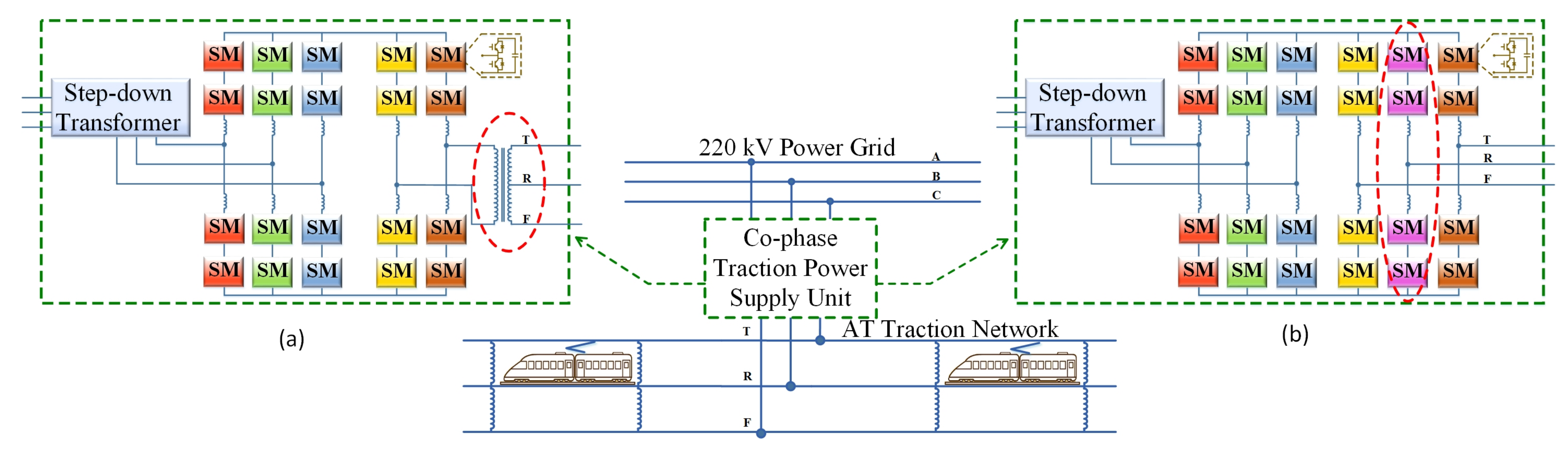
If the co-phase power-supply scheme that has been proposed in the most paper is applied to the AT power-supply system, as shown in Figure 2a, an auto-transformer is required between the back-to-back structure of the topology and the traction network. The structure proposed in this paper, as shown in Figure 2b, uses a bridge leg to replace the role of the auto-transformer. The newly added bridge leg should be connected to the rail (i.e., the R line in Figure 2), and the modules on it should be controlled to ensure that the voltage between the contact grid (i.e., the T line in Figure 2) and the rail, as well as the voltage between the positive feeder (i.e., the F line in Figure 2) and the rail, are 27.5 kV single-phase AC voltages of equal amplitude and 180 degrees difference in phase, i.e., and . The functionality and advantages of this scheme will be analyzed and illustrated in detail in Section 4.
2.2. The Mathematical Model of the Proposed Scheme
As for the mathematical model, the topology proposed in this paper is a back-to-back structure consisting of the rectifier side, which is composed of three bridge legs corresponding to the three-phase step-down transformer, and the inverter side, which is composed of three bridge legs corresponding to the two single-phase output voltages to the traction network. The mathematical model of the rectifier side and the inverter side will be illustrated separately below.
2.2.1. The Rectifier Side
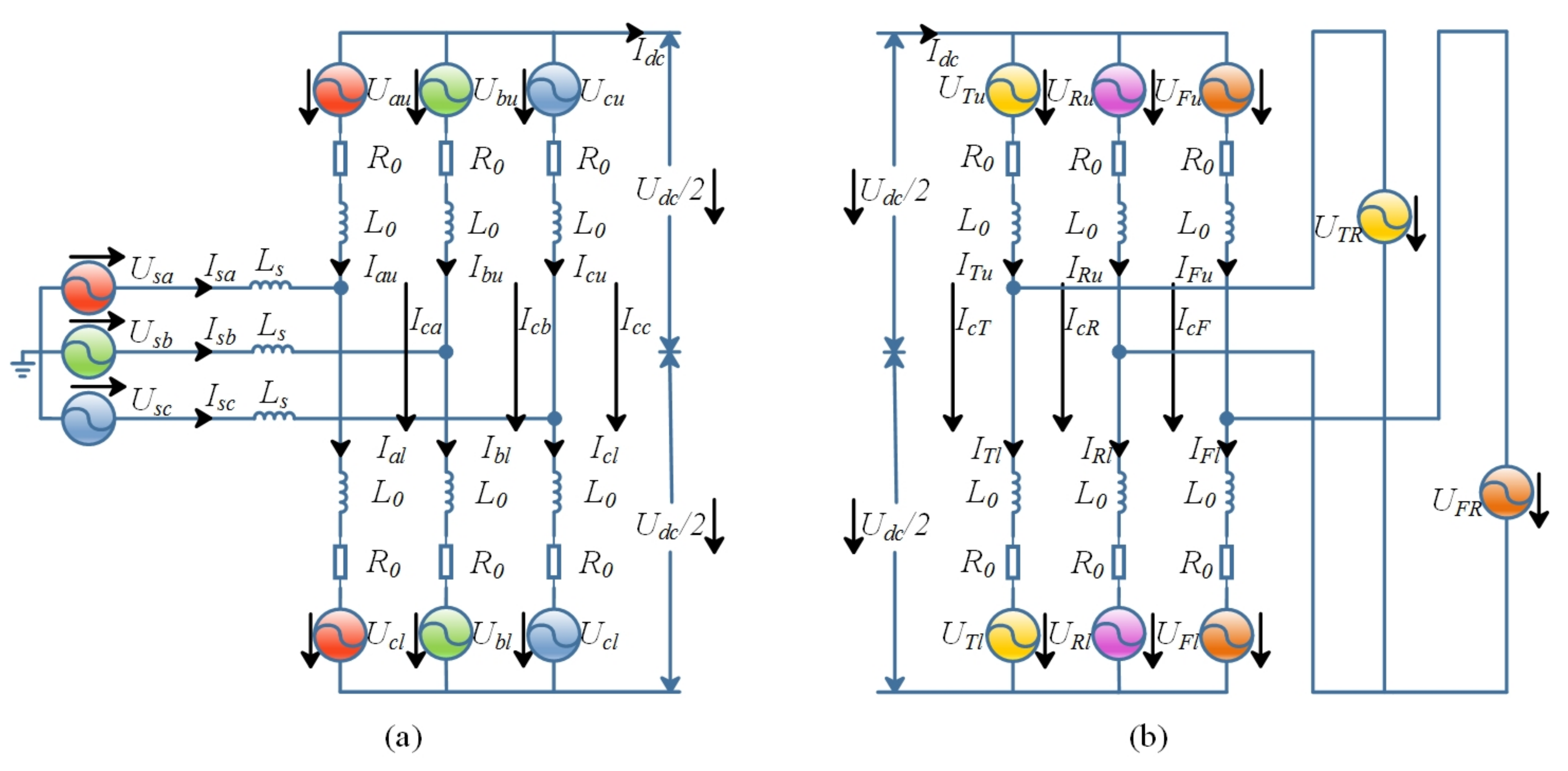
According to the equivalent circuits as shown in Figure 3 and Kirchhoff’s voltage law, we have Equation (1) [42]
In Equation (1), , and is so small that can be ignored. Bringing in , adding and subtracting the two-equation in (1) from each other yields (2)
As shown in Figure 3, is the AC side source current, is the circulating current, is the upper arm current, is the lower arm current, and is the DC bus current, the relationship between them is as follows [43].
As for the instantaneous power, the rectifier side was analyzed, and the results were as follows [43]
The expression for instantaneous power is obtained by bringing (7) and (8) into (6).
2.2.2. The Inverter Side
The inverter side uses a bridge leg to replace the AT self-coupling transformer. As for voltage of the inverter side, the voltage between the T line and the R line as well as the voltage between the F line and the R line are two 27.5 kV single-phase AC voltages of equal amplitude and difference in phase, i.e., and .
As for the current of the inverter side, the current in the upper and lower bridge arms is a superposition of the AC side current and the circulating current, while the circulating current is a superposition of the fundamental frequency component, the double frequency component, and the DC component, which is come from the DC bus current. In addition, regarding the output side current, When the train is within one AT interval before or after the substation, there will be current on the R line. In contrast, when the train is not within one AT interval before or after the substation, there will be no current on the R line, and the T/F line current’s amplitude is a constant value.
As for the instantaneous power, there will be an equal distribution of the direct-current across the three bridge legs, ignoring the harmonic component, and the expressions for the voltages are as below [43].
And the current expressions are as below [43].
And the expression for the instantaneous power in the bridge legs are as follows.
3. Control System for The Proposed Topology
According to the analysis of the operation principle above, the control objectives below need to be met as a co-phase power-supply device, For the rectifier side, the control objectives of no negative sequence current, reactive current, and harmonic component on the rectifier side should be met, and at the same time, the DC bus voltage should be stabilized near the reference value, so as to avoid power quality problems caused by the traction network and to maintain the stability of the DC side. For the inverter side, it is necessary to achieve the control objectives of controllable amplitude and phase of the output voltage to ensure that the entire traction network substations have the voltage of the same phase and amplitude. In addition, because of the newly added bridge leg, it is necessary to ensure that the voltage between the contact network and the rail as well as the voltage between the positive feeder and the rail are 27.5 kV single-phase AC voltages of equal amplitude and in phase.
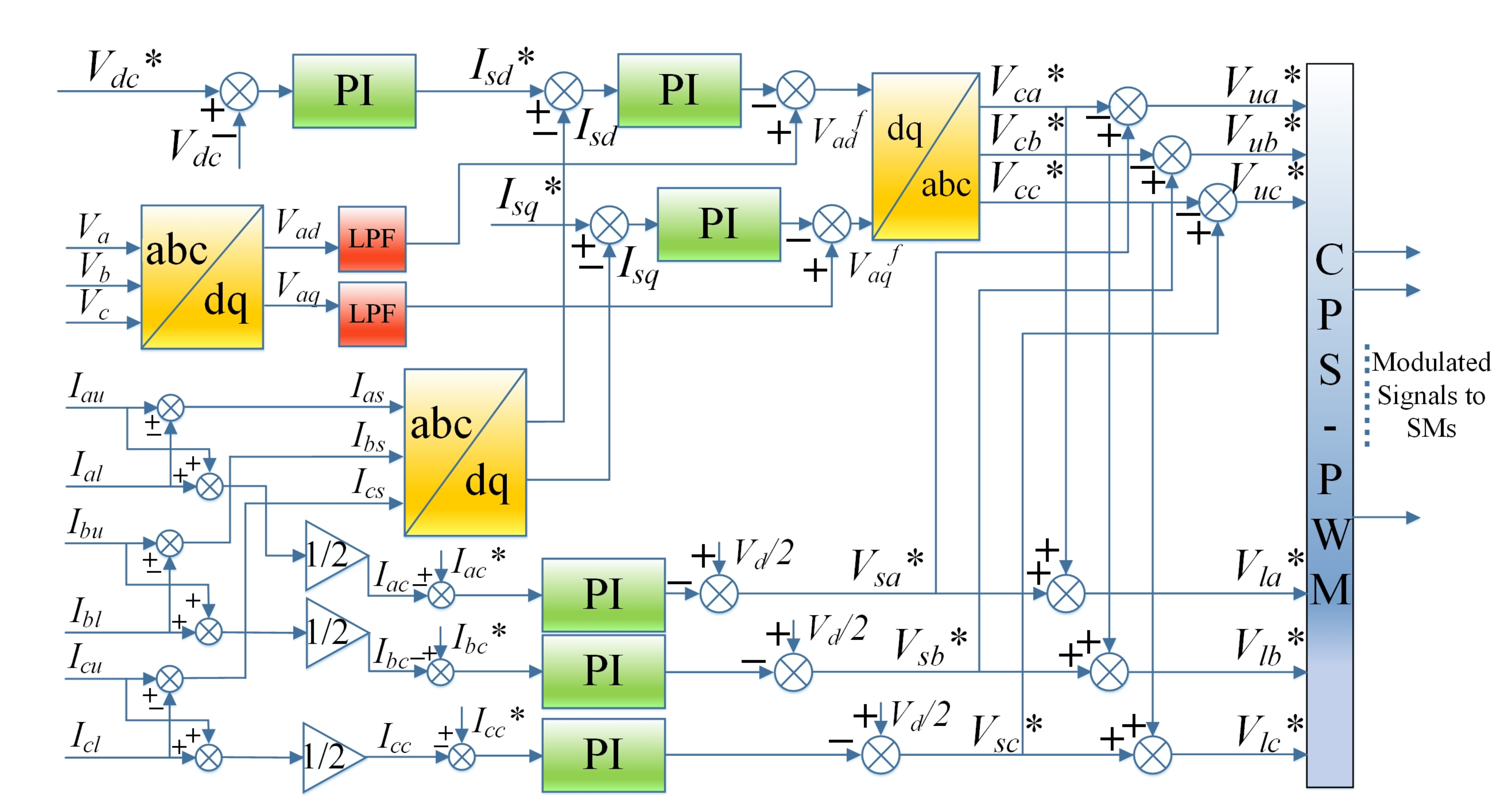
3.1. The Control System for the Rectifier Side
As for the rectifier side, according to the mathematical model in Section 2, add and subtract Equation (1) to each other, the following equation can be obtained [43].
Defining as and as , we can get the following equation [43].
And we can get and if there is and [43].
By using the PI controller, according to the following expression, we can get and .
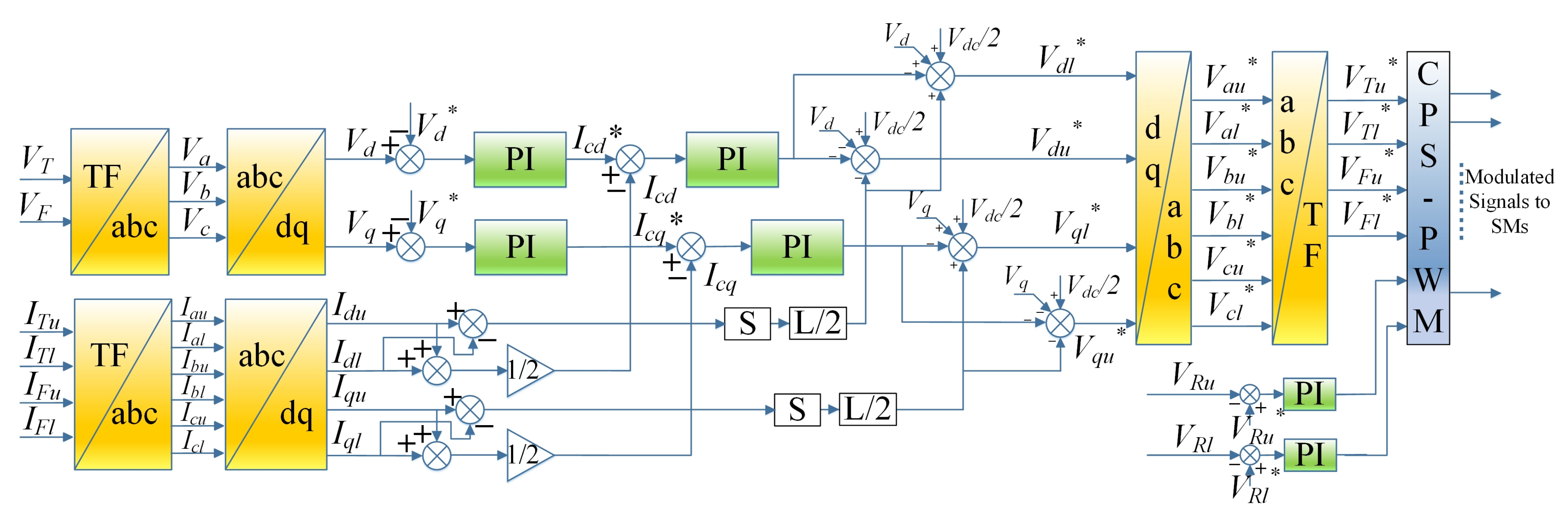
3.2. The Control System for the Inverter Side
As for the inverter side, based on the mathematical model built for the inverter side, the following expression can be obtained [42].
Taking the T line as an example, with the PI controller, we can get the upper and lower bridge arm reference voltages by the following expression.
From this, the control system on the inverter side can be get.
As shown in Figure 5, since the output voltages are two single-phase AC voltages of equal amplitude and difference in phase, if we want to convert them to the coordinate system for control, we need to converter them to the ABC coordinate system first. By converting to the A-phase and to the sum of the B phase and C phase, we can convert them to the ABC coordinate system and then control them.
4. The Verification of the Proposed Topology by Simulation
In this section, the functionality of the proposed topology is verified by simulation. The simulation builds a realistic model of AC-DC-AC substation. The grid voltage of the system is 220 kV. Then connect the grid to a step-down transformer to transfer the voltage to the rated phase voltage of 27.5 kV on the AC grid side. Then connect the secondary side of the step-down transformer to the MMC-based back-to back structure. The rated voltage of the DC bus of the back-to-back structure is 80 kV. In addition, the rated phase voltage on the output side is 27.5 kV.
As for the functions that the device needs to meet, as analyzed above, the proposed co-phase power-supply device for the AT power-supply mode needs to meet the following functions: the rectifier side should eliminate negative sequence current, reactive current, and harmonics to ensure that it does not bring power quality problems for the power grid, and the DC bus voltage needs to be stabilized near the reference value. As for the inverter side, it is necessary to ensure that the output voltage’s amplitude and phase can be controlled at the control reference value.
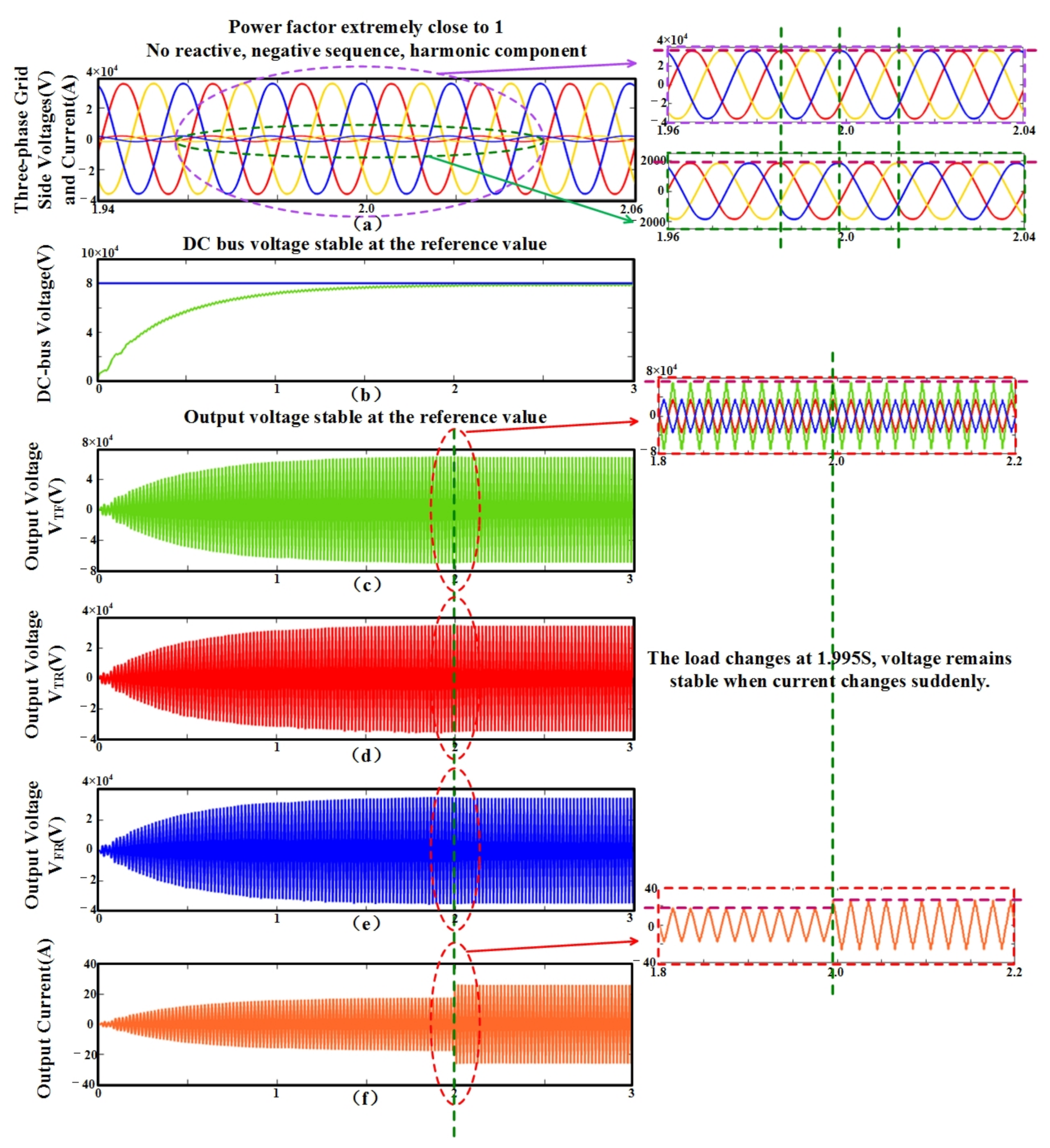
It can be seen from Figure 6a that the voltage and current on the rectifier side basically have no phase difference, i.e., their power factor is basically 1, which means that there is no reactive current component. The three-phase voltage and current waveforms have stable amplitude and good waveforms without negative sequence and harmonic components, meeting the functional requirements of the co-phase power-supply scheme on the rectifier side.
It can be seen from Figure 6b that the DC bus voltage can rise and stabilize at the reference value with minimal fluctuations, meeting the requirement of the DC bus voltage.
It can be seen from Figure 6c,d that the voltage’s amplitude and phase on the output side can be stabilized at the reference value. And to verify that when the current changes suddenly, the voltage remains stable and basically unchanged. The load mutation is set at 1.995 s, and the current changes suddenly with it. It can be seen from Figure 6c,d that the voltage remains stable and basically unchanged. Therefore, the inverter side can meet the functional requirements of the co-phase power-supply scheme.
In summary, the simulation verified that the entire system can meet the functional requirements of the co-phase power-supply scheme.
5. The Advantages Analysis of the Proposed Topology
After verifying that the proposed co-phase power-supply device topology can meet the functional requirements of the co-phase power-supply scheme, the advantages of the proposed topology needs to be analyzed and discussed.
Then the two schemes need to be compared in the same scenario. It is assumed that the scenarios of the two schemes are both AC-DC-AC substations with a rated power of 40 MW. The step-down transformer transfers the 220 kV grid voltage to the rated grid-side phase voltage of 27.5 kV, the system rated DC bus voltage is 80 kV, and the system output side rated phase voltage is 27.5 kV. As for the MMC structure, there are both three bridge legs on the rectifier side and the inverter side. Each bridge leg is divided into the upper and lower bridge arms. There are 40 sub-modules on each bridge arm. The rated capacitor voltage of the sub-module is 2 kV, and the switching device is selected to be Infineon-FZ1500R33HE3.
The following section will specifically analyze the advantages and disadvantages of the two schemes in different aspects under this scenario.
5.1. The Comparative Analysis of Current Stress of the Switching Devices
From the perspective of the current stresses borne by switching devices in the topology, qualitative analysis shows that since the inverter side adds a bridge leg, the DC component flowing from the DC bus into the inverter side bridge leg is changed from the original two equal parts to three equal parts, so that the DC component in the bridge leg decreases. As for the AC output side, when the locomotive is in one AT interval before or after the substation, there will be a current inflow on the newly added bridge leg, because the sum of the TRF line current is zero, T line current outflow, and R and F line current inflow, so the current’s amplitude of the bridge leg connected to the F line is reduced. In addition, when the locomotive is not located in one AT interval before or after the substation, there is no difference in the AC current with other topology. Therefore, in a comprehensive view, when the power is constant, the current stress of the switching devices in the inverter side bridge leg of the topology proposed in this paper is smaller.
At the same time, quantitative analysis shows that the current stress value of the inverter side switching device is indeed smaller. The calculation is based on the system rated at 40 MW, and the calculation is according to the maximum current may appear in the bridge leg. For example, on the rectifier side, since UI, kV, the current A can be obtained, and because , the reference value of is 80 kV, A can be obtained, thus the maximum current in the bridge arm is A. However, on the inverter side, the output voltages are two single-phase voltages, thus UI, kV, the current A can be obtained, so the maximum current in the bridge arm is A. Therefore, in summary, the current maximum value of the switching devices on the rectifier and inverter sides is, respectively 509.51 A and 680.93 A.
It is similarly calculated that the maximum currents in the bridge arm of the rectifier-inverter side of the already proposed topology are respectively 509.51 A and 764.24 A.
It can be seen that the current stress of the inverter side switching devices of the topology proposed in this paper is significantly reduced.
5.2. The Comparative Analysis of the Power Loss of the Whole System
From the perspective of power loss, the loss of the device can be calculated theoretically. The power loss of a switching device consists of two parts: the conduction loss and the turn-on turn-off loss. The expression is as below [45,46].
The and means the total power loss of the IGBT and diode separately, and the are the conduction loss and turn-on turn-off losses of the IBGT in a fundamental output period, and the are the conduction loss and turn-off loss of the diode. All these losses make up the total loss of a switching device. These losses can be calculated individually by these equations below [45,46].
In these equations, and can be obtained based on the rated values, and and can be obtained based on the corresponding current values and the output characteristic curves of the switching devices provided in [47]. can be obtained from the corresponding current and the device loss curves provided in [47]. can also be obtained from the corresponding current and the output characteristic curve. Set the rated power of the system to 40 MW. From this, it can be calculated that the power loss of all switching devices in the topology proposed in this paper in one fundamental period is 613.67 kW, while the power loss of the switching devices in the topology has been commonly proposed is 502.28 kW.
At the same time, the Infineon Online Power Simulation Tool (IPOSIM) (produced by Infineon in Munich, Germany and provided on the official website) can be used to approximate the power loss of the switching device after setting the value of the DC link voltage, RMS current, frequency, and the switching frequency on it. The Infineon Online Power Simulation Tool (IPOSIM) (produced by Infineon in Munich, Germany and provided on the official website) calculation result of the power loss of the topology proposed in this paper is 625.44 kW, while the result of the topology commonly proposed is 536.80 kW. However, from the perspective of switching devices, the power loss proposed in this paper is relatively high, from the perspective of the entire system of the scheme, the scheme proposed in this paper eliminates an auto-transformer. Take an auto-transformer with a nameplate capacity of 31.5 MVA as an example. Its actual electromagnetic capacity is only 13.3 MVA, saving it can save about $30,000 and save about 0.5% of energy loss, which is 66.5 kW.
So as for the loss of the whole system, we need to add the loss of the transformer based on the loss of switching devices. Because of the high efficiency of high-voltage large-capacity transformers, we set the efficiency of high-voltage large-capacity transformers at 99.5%, and set the rated system power to 40 MW, then the efficiency of the whole system (i.e., considering the previous step-down transformer and the energy losses of the switching devices) is 97.96%, and the efficiency of the whole system of the commonly proposed scheme (i.e., considering the previous step-down transformer, an auto-transformer and the energy losses of the switching devices) is 97.71%.
Although the numerical difference in efficiency between the two systems is not massive, considering that the railway system is a large-capacity system, for example, with a rated capacity at 40 MW, a difference of 0.25% would result in an energy difference of 100 kWh per hour, so the scheme proposed in this paper can save 100 kWh per hour compared to the commonly proposed scheme, which has excellent economic benefits in the long term.
6. Conclusions
Against the background that there is no previous co-phase power-supply scheme especially designed for the AT power-supply mode, this article proposes a co-phase power-supply scheme for the AT power-supply mode traction power-supply system that has become the main power-supply mode for the high-speed railways. The feasibility and functionality of the scheme are verified by establishing mathematical models, creating control systems, and simulating. It proves that the scheme proposed in this paper can meet the needs of the co-phase power-supply system. In addition, on this basis, a comparative analysis with the system that has been commonly proposed has verified that this scheme has obvious advantages in the current stress of the switching device and the power loss of the entire system. Therefore, this solution is a more suitable co-phase power-supply scheme for the AT power-supply mode traction power-supply system.
This scheme can be used in the AT traction power-supply system of high-speed railways to be installed in substations to eliminate neutral section and at the same time eliminate power quality problems such as negative sequence, reactive power, and harmonics injected into the public grid. It ensures the safe and economical operation of the traction network and the power grid and promotes the increase in the speed of high-speed railways. The application value of this project can be popularized in the traction power-supply system of high-speed electrified railways around the world, and remove existing obstacles for the development of electrified railways worldwide.
Author Contributions
Conceptualization, investigation and data curation, S.W.; methodology, S.W. and M.W. and Y.W.; software and validation, formal analysis, S.W.; writing—Original draft preparation, S.W.; writing—Review and editing, M.W. and Y.W.; supervision and project administration, M.W. All authors have read and agreed to the published version of the manuscript.
Funding
This research was funded by Fundamental Research Funds for the Central Universities with grant number 2018YJS150.
Data Availability Statement
Data sharing not applicable. No new data were created or analyzed in this study. Data sharing is not applicable to this article.
Conflicts of Interest
The authors declare no conflict of interest.
Abbreviations
The following abbreviations are used in this manuscript:
| AT | Auto-transformer |
| MMC | Modular multilevel converter |
| SVC | Static var compensator |
| STATCOM | Static synchronous compensator |
| APF | Active power filter |
| APC | Active power compensator |
| RPC | Railway power conditioner |
| HPQC | Hybrid power quality conditioner |
| HEMPQC | Hybrid electrical magnetic power quality compensator |
| CHB | Cascaded H-Bridge |
| Voltage of the contact network to the rails (kV) | |
| Voltage of the positive feeder to the rails (kV) | |
| The voltage of phase i on the AC grid side connected to the back-to-back rectifier side based on MMC (i = a, b, c) (kV) | |
| L | The integrated equivalent inductance in the single-phase equivalent circuit of MMC.(mH) |
| Upper arm current of MMC back-to-back structure (A) | |
| Lower arm current of MMC back-to-back structure (A) | |
| Sum of the voltages of the i-phase upper bridge arm sub-modules of the MMC structure (kV) | |
| Sum of the voltages of the i-phase lower bridge arm sub-modules of the MMC structure (kV) | |
| Voltage of the DC bus in the MMC back-to-back structure (kV) | |
| The source current of AC grid side connected to the back-to-back rectifier side based on MMC (A) | |
| The circulating current of the MMC-based back-to-back structure (A) | |
| Current of the DC bus in the MMC back-to-back structure (A) | |
| Instantaneous power of the A-phase upper bridge arm (kW) | |
| LD | linear dichroism |
| Instantaneous power of the A-phase lower bridge arm(kW) | |
| Defined as (kV) | |
| Defined as (kV) | |
| Total power loss of the switching device in a fundamental output period (mJ) | |
| Total power loss of the IGBT in a fundamental output period (mJ) | |
| Total power loss of the diode in a fundamental output period (mJ) | |
| Conduction loss of the IGBT in a fundamental output period (mJ) | |
| Turn-on loss of the IGBT in a fundamental output period (mJ) | |
| Turn-off loss of the IGBT in a fundamental output period (mJ) | |
| Conduction loss of the diode in a fundamental output period (mJ) | |
| Turn-off loss of the diode in a fundamental output period (mJ) |
References
- Zhang, Z.; Zheng, T.Q.; Li, K.; Hao, R.; You, X.; Zhang, Z.; Yang, J. Smart Electric Neutral Section Executer Embedded With Automatic Pantograph Location Technique Based on Voltage and Current Signals. IEEE Trans. Transp. Electrif. 2020, 6, 1355–1367. [Google Scholar] [CrossRef]
- Wang, S.; Zhang, L.; Yu, G.; Dong, E.; Zou, J.; Cong, Y.; Tian, Y. Hybrid phase-controlled circuit breaker with switch system used in the railway auto-passing neutral section with an electric load. CSEE J. Power Energy Syst. 2019, 5, 545–552. [Google Scholar]
- Yuan, J.X.; Zhou, N.; Xiao, F.R.; Min, Y.Z. Study on the Control Method and the Uninterrupted Phase-Separation Passing System with Voltage Compensation Function. Trans. China Electrotech. Soc. 2020, 1–12. [Google Scholar]
- Qiu, W.J.; Hu, Q. Research on Technologies for electronics switch automatic passing of neutral section on heavy haul railway. Electr. Railw. 2019, 6, 17–21. [Google Scholar]
- Canales, J.M.; Aizpuru, I.; Iraola, U.; Barrena, J.A.; Barrenetxea, M. Medium-Voltage AC Static Switch Solution to Feed Neutral Section in a High-Speed Railway System. Energies 2018, 11, 2740. [Google Scholar] [CrossRef] [Green Version]
- Han, Z.Q.; Shen, R.; Zhou, Y.Z. Simulation of Flexible Automatic Neutral Section Passing System Based on RTDS. Electr. Drive Locomot. 2019, 3, 6–11. [Google Scholar]
- Paul, P.A.; Anju, U.D.; Anoop, M.P.; Pallan, M.R.; Roshna, N.K.; Sunny, A. Effects of two phase traction loading on a three phase power transformer. In Proceedings of the 2014 Annual International Conference on Emerging Research Areas: Magnetics, Machines and Drives (AICERA/iCMMD), Kottayam, India, 24–26 July 2014; pp. 1–5. [Google Scholar]
- Joseph, V.P.; Thomas, J. Power quality improvement of AC railway traction using railway static power conditioner a comparative study. In Proceedings of the 2014 International Conference on Power Signals Control and Computations (EPSCICON), Thrissur, India, 6–11 January 2014; pp. 1–6. [Google Scholar]
- Gunavardhini, N.; Chandrasekaran, M.; Sharmeela, C.; Manohar, K. A case study on Power Quality issues in the Indian Railway traction sub-station. In Proceedings of the 2013 7th International Conference on Intelligent Systems and Control (ISCO), Coimbatore, India, 4–5 January 2013; pp. 7–12. [Google Scholar]
- Hu, H.; He, Z.; Gao, S. Passive Filter Design for China High-Speed Railway With Considering Harmonic Resonance and Characteristic Harmonics. IEEE Trans. Power Deliv. 2015, 1, 505–514. [Google Scholar] [CrossRef]
- Hu, L.; Morrison, R.E. The stability and power flow limits of an electrified railway system with voltage controlled SVCs. In Proceedings of the 1994 Fifth International Conference on Power Electronics and Variable-Speed Drives, London, UK, 26–28 October 1994; pp. 562–567. [Google Scholar]
- Ledwich, G.; George, T.A. Using phasors to analyze power system negative phase sequence voltages caused by unbalanced loads. IEEE Trans. Power Syst. 1994, 3, 1226–1232. [Google Scholar] [CrossRef]
- Lee, S.H.; Bae, I.S.; Jung, C.H.; Kim, J.-O. A study on system stability improvement of distribution system with high speed electric railway using STATCOM. In Proceedings of the 2003 IEEE PES Transmission and Distribution Conference and Exposition (IEEE Cat. No.03CH37495), Dallas, TX, USA, 7–12 September 2003; Volume 1, pp. 61–67. [Google Scholar]
- Wu, L.R.; Mingli, W. Single-phase cascaded H-bridge multi-level active power filter based on direct current control in AC electric railway application. IET Power Electron. 2017, 6, 637–645. [Google Scholar] [CrossRef]
- Shen, W.T. Study on Experiment and Modification of a Combined Co-Phase Supply System with a Single-Phase and Three-Phase Modular; Southwest Jiaotong University: Chengdu, China, 2016. [Google Scholar]
- Shu, Z.; Xie, S.; Lu, K.; Zhao, Y.; Nan, X.; Qiu, D.; Zhou, F.; Gao, S.; Li, Q. Digital Detection, Control, and Distribution System for Co-Phase Traction Power Supply Application. IEEE Trans. Ind. Electron. 2013, 5, 1831–1839. [Google Scholar] [CrossRef]
- Dai, N.; Wong, M.; Lao, K.; Wong, C. Modeling and control of a railway power conditioner in co-phase traction power system under partial compensation. IET Power Electron. 2014, 5, 1044–1054. [Google Scholar] [CrossRef] [Green Version]
- Tanta, M.; Pinto, J.G.; Monteiro, V.; Martins, A.P.; Carvalho, A.S.; Afonso, J.L. Topologies and Operation Modes of Rail Power Conditioners in AC Traction Grids: Review and Comprehensive Comparison. Energies 2020, 13, 2151. [Google Scholar] [CrossRef]
- Dai, N.Y.; Lao, K.W.; Wong, M.C.; Wong, C.K. Hybrid power quality conditioner for co-phase power supply system in electrified railway. IET Power Electron. 2012, 7, 1084–1094. [Google Scholar] [CrossRef]
- Lao, K.; Wong, M.; Dai, N.Y.; Wong, C.; Lam, C. Analysis of DC-Link Operation Voltage of a Hybrid Railway Power Quality Conditioner and Its PQ Compensation Capability in High-Speed Cophase Traction Power Supply. IEEE Trans. Power Electron. 2016, 2, 1643–1656. [Google Scholar] [CrossRef]
- Lao, K.; Wong, M.; Dai, N.; Lam, C.; Wong, C.; Lam, L.W. Analysis in the Effect of Co-phase Traction Railway HPQC Coupled Impedance on Its Compensation Capability and Impedance-Mapping Design Technique Based on Required Compensation Capability for Reduction in Operation Voltage. IEEE Trans. Power Electron. 2017, 4, 2631–2646. [Google Scholar] [CrossRef]
- Lao, K.; Wong, M.; Dai, N.; Lam, C.; Wang, L.; Wong, C.K. Analysis of the Effects of Operation Voltage Range in Flexible DC Control on Railway HPQC Compensation Capability in High-Speed Co-phase Railway Power. IEEE Trans. Power Electron. 2018, 2, 1760–1774. [Google Scholar] [CrossRef]
- Chen, B.; Zhang, C.; Tian, C.; Wang, J.; Yuan, J. A Hybrid Electrical Magnetic Power Quality Compensation System With Minimum Active Compensation Capacity for V/V Cophase Railway Power Supply System. IEEE Trans. Power Electron. 2016, 6, 4159–4170. [Google Scholar] [CrossRef]
- Xiong, C.; Ma, J.; Wu, X.; Wang, S.; Feng, X. Virtual co-phase traction power supply system adopting the cascaded H-bridge multilevel converter. Electron. Lett. 2016, 10, 865–866. [Google Scholar] [CrossRef]
- Li, L.; Wu, M.; Wu, S.; Li, J.; Song, K. A Three-Phase to Single-Phase AC-DC-AC Topology Based on Multi-Converter in AC Electric Railway Application. IEEE Access 2019, 7, 111539–111558. [Google Scholar] [CrossRef]
- He, X.; Peng, J.; Han, P.; Liu, Z.; Gao, S.; Wang, P. A Novel Advanced Traction Power Supply System Based on Modular Multilevel Converter. IEEE Access 2019, 7, 165018–165028. [Google Scholar] [CrossRef]
- Ma, Q.A. Study on Some Problems of Traction Power Supply System in High-Speed Railway; Southwest Jiaotong University: Chengdu, China, 2013. [Google Scholar]
- Takeda, M.; Murakami, S.; Iizuka, A.; Hirakawa, M.; Kishida, M.; Hase, S.; Mochinaga, H. Development of an SVG Series for Voltage Control Over Three-phase Unbalance Caused by Railway Load. In Proceedings of the IPEC Yokohama 1995 Conference Records, Yokohama, Japan, 3–7 April 1995; pp. 603–608. [Google Scholar]
- Ando, M.; Mochinaga, Y.; Kato, T.; Yoshizawa, J.; Gomi, T.; Miyashita, T.; Funahashi, S.; Nishitoba, M.; Oozeki, S. Development of railway static power conditioner used at substation for Shinkansen. In Proceedings of the PCC-Osaka 2002 Conference Records, Osaka, Japan, 2–5 April 2002; pp. 1108–1111. [Google Scholar]
- Kai, M.; Ohnishi, M.; Masui, T.; Noguchi, M.; Morishima, N.; Horita, Y. Single phase STATCOM for feeding system of Tokaido Shinkansen. In Proceedings of the IPEC-Sapporo 2010 Conference Records, Sapporo, Japan, 21–24 June 2010; pp. 2165–2170. [Google Scholar]
- Xu, Z.J. Study on AT Network Models; Southwest Jiaotong University: Chengdu, China, 2015. [Google Scholar]
- Wu, M.L.; Wu, L.R. Experimental Verification of Mathematical Model and Impedance Matching of the Scott Connected Balance Transformer. J. China Railw. Soc. 2007, 2, 39–44. [Google Scholar]
- Wu, M.L.; Fan, Y.; Zheng, T.Q. Operational Performance of the Cross-Connected Traction Transformer (1)—Mathematical Model and Theoretical Analysis. Trans. China Electrotech. Soc. 2004, 9, 11–17. [Google Scholar]
- Zhao, Y.L. Secondary Midpoint Withdrawable Single-Phase Traction Transformer; Beijing Jiaotong University: Beijing, China, 2014. [Google Scholar]
- Wu, L.R.; Guo, Y.P.; Yi, Y.J.; Huang, X.Y.; Liu, Z.Q.; Wen, W.S.; Zhang, X.S.; Fan, Z.A.; Xu, G. Development of a single-phase traction transformer for the AT power supply. Electr. Railw. 1998, 4, 3–5. [Google Scholar]
- Hu, J.X.; Zhou, F.Y. Status and Development of Neutral Section Passing Technology for Electrified Railway Trains. Electr. Drive Locomot. 2019, 3, 1–5. [Google Scholar]
- Gao, S.W. Study on Control Strategy for Device of Electronic Switch Type for Passing of Phase Break. Electr. Railw. 2020, 3, 16–20. [Google Scholar]
- Wang, S.H. Study of Uninterruptible Power Automatic Passing through Neutral Section Device for High Speed EMU; Beijing Jiaotong University: Beijing, China, 2012. [Google Scholar]
- Tanta, M.; Monteiro, V.; Sousa, T.J.C.; Martins, A.P.; Carvalho, A.S.; Afonso, J.L. Power quality phenomena in electrified railways: Conventional and new trends in power quality improvement toward public power systems. In Proceedings of the 2018 International Young Engineers Forum (YEF-ECE), Costa da Caparica, Portugal, 4 May 2018; pp. 25–30. [Google Scholar]
- Wu, L.R. Power Quality Compensation Technology in Electric Railways Based on 27.5 kV Straight Hanging Cascaded APF; Beijing Jiaotong University: Beijing, China, 2017. [Google Scholar]
- Gazafrudi, S.M.M.; Langerudy, A.T.; Fuchs, E.F.; Al-Haddad, K. Power Quality Issues in Railway Electrification: A Comprehensive Perspective. IEEE Trans. Ind. Electron. 2015, 5, 3081–3090. [Google Scholar] [CrossRef]
- Li, B.B. Research on Modular Multilevel Converter and Its Control Schemes; Harbin Institute of Technology: Harbin, China, 2012. [Google Scholar]
- Sharifabadi, K.; Harnefors, L.; Nee, H.P.; Norrga, S.; Teodorescu, R. Design, Control, and Application of Modular Multilevel Converters for HVDC Transmission Systems; John Wiley & Sons Ltd: Chichester, West Sussex, UK, 2016; pp. 34–148. [Google Scholar]
- Yang, X.F.; Sun, H.; Zheng, T.Q. Application of Double-modulation-wave Carrier Phase-shifted SPWM in Modular Multilevel Converters. Electr. Drive 2011, 10, 15–20. [Google Scholar]
- Rohner, S.; Bernet, S.; Hiller, M.; Sommer, R. Modulation, Losses, and Semiconductor Requirements of Modular Multilevel Converters. IEEE Trans. Ind. Electron. 2010, 8, 2633–2642. [Google Scholar] [CrossRef]
- Rodrigues, S.; Papadopoulos, A.; Kontos, E.; Todorcevic, T.; Bauer, P. Steady-State Loss Model of Half-Bridge Modular Multilevel Converters. IEEE Trans. Ind. Appl. 2016, 3, 2415–2425. [Google Scholar] [CrossRef]
- Wiesenthal; Lübke, C. Technical Information, EUPEC IGBT Modules FZ1500R33HE3. 2016. Available online: https://www.infineon.com/cms/en/product/power/igbt/igbt-modules/fz1500r33he3/ (accessed on 4 January 2021).
Figure 1.
Traditional AT traction power-supply system components: (a) three-phase-two-phase balanced wiring transformer; (b) three-phase cross wiring transformer; (c) V/X wiring transformer; (d) secondary midpoint withdrawable single-phase wiring transformer.
Figure 1.
Traditional AT traction power-supply system components: (a) three-phase-two-phase balanced wiring transformer; (b) three-phase cross wiring transformer; (c) V/X wiring transformer; (d) secondary midpoint withdrawable single-phase wiring transformer.

Figure 2.
Co-phase power-supply system topologies: (a) The scheme already have been proposed but is not specific to AT supply mode; (b) The scheme proposed in this paper for AT supply mode.
Figure 2.
Co-phase power-supply system topologies: (a) The scheme already have been proposed but is not specific to AT supply mode; (b) The scheme proposed in this paper for AT supply mode.

Figure 3.
The equivalent circuit of the proposed topology: (a) Rectifier side equivalent circuit of the proposed topology; (b) Inverter side equivalent circuit of the proposed topology.
Figure 3.
The equivalent circuit of the proposed topology: (a) Rectifier side equivalent circuit of the proposed topology; (b) Inverter side equivalent circuit of the proposed topology.

Figure 4.
The control system for the rectifier side of the proposed topology.

Figure 5.
The control system for the inverter side of the proposed topology.

Figure 6.
The simulation results of the proposed topology: (a) Voltage and current on the three-phase input side of the proposed topology; (b) DC-bus voltage of the proposed topology; (c) Voltage between T line and F line on the output side of the proposed topology; (d) Voltage between T line and R line on the output side of the proposed topology; (e) Voltage between F line and R line on the output side of the proposed topology; (f) Current on the output side of the proposed topology.


Table 1.
Comparative analysis of neutral section passing schemes in terms of functionality, operation, cost and maintenance.
Table 1.
Comparative analysis of neutral section passing schemes in terms of functionality, operation, cost and maintenance.
| Comparative Aspects | Specific Comparison Content | Power-Off Neutral Section Passing Scheme | Live-Line Neutral Section Passing Scheme | ||||
|---|---|---|---|---|---|---|---|
| Manual Power-off Neutral Section Passing Scheme | Vehicle-Mounted
Automatic Neutral Section Passing Scheme | Column Switch
Neutral Section Passing Scheme | Mechanical Switch
Ground Automatic Neutral Section Passing Scheme | Electronic Switch
Ground Automatic Neutral Section Passing Scheme | Flexible Ground Automatic Neutral Section Passing Scheme | ||
| Functionality | power-loss time (speed loss) | Long power-loss time, big speed loss | Long power-loss time, big speed loss | Relatively long power-loss time, relatively big speed loss | Relatively short power-losstime, relatively small speed loss | Short power-loss time, small speed loss | Completely realize uninterrupted power neutral section passing |
| over-voltage | Easy to cause over-voltage shock | Over-voltage shock | Over-voltage shock | Mechanical switch brings operating over-voltage | the operating over-voltage caused by mechanical switches solved | No over- voltage shock | |
| Operation | the fatigue degree of the train crew | Easy to cause train crew fatigue | No train crew operation required | No train crew operation required | No train crew operation required | No train crew operation required | No train crew operation required |
| Cost and maintenance | Investment | Small | Relatively small | Relatively small | Relatively big | Relatively big | Big |
| Switch lifetime (if included in the scheme) | None | None | None | Short switch lifetime | Long switch lifetime | Long switch lifetime | |
Table 2.
Comparative analysis of the performance of the schemes for the power quality problems.
| Name of Each Scheme | Negative Sequence | Harmonics | Reactive Power | Others |
|---|---|---|---|---|
| Passive filter | None | Govern harmonics, but only eliminate specific harmonics. And it is easy to resonate with the system impedance and cause harmonic amplification | Govern reactive power, but with poor continuity, which cannot be compensated well due to the frequent fluctuation of the traction load. | Require large space for installation and high implementation cost. the change in the filter parameters affected by the heat or lifetime, which gradually caused misoperations in the filter functionality |
| SVC | Compensation for negative sequence | Limited harmonic suppression and it will bring harmonic problems by itself | Compensation for reactive power | May produce series- parallelVert resonance |
| STATCOM | Compensation for negative sequence | Low harmonic content | Fast response for reactive power compensation | Small Land area |
| APF | Compensation for negative sequence | Harmonic suppression | Compensation for reactive power | The cost is high when used to compensate negative sequence and reactive power, so it is usually combined with passive compensation. |
| RPC | Effective realization of reactive power compensation | Effective implementation of negative sequence compensation | Effective harmonic compensation | None |
Publisher’s Note: MDPI stays neutral with regard to jurisdictional claims in published maps and institutional affiliations. |
© 2021 by the authors. Licensee MDPI, Basel, Switzerland. This article is an open access article distributed under the terms and conditions of the Creative Commons Attribution (CC BY) license (http://creativecommons.org/licenses/by/4.0/).
Share and Cite
MDPI and ACS Style
Wu, S.; Wu, M.; Wang, Y. A Novel Co-Phase Power-Supply System Based on Modular Multilevel Converter for High-Speed Railway AT Traction Power-Supply System. Energies 2021, 14, 253. https://0-doi-org.brum.beds.ac.uk/10.3390/en14010253
AMA Style
Wu S, Wu M, Wang Y. A Novel Co-Phase Power-Supply System Based on Modular Multilevel Converter for High-Speed Railway AT Traction Power-Supply System. Energies. 2021; 14(1):253. https://0-doi-org.brum.beds.ac.uk/10.3390/en14010253
Chicago/Turabian StyleWu, Si, Mingli Wu, and Yi Wang. 2021. "A Novel Co-Phase Power-Supply System Based on Modular Multilevel Converter for High-Speed Railway AT Traction Power-Supply System" Energies 14, no. 1: 253. https://0-doi-org.brum.beds.ac.uk/10.3390/en14010253
Note that from the first issue of 2016, this journal uses article numbers instead of page numbers. See further details here.