1. Introduction
By 2050, the European Union’s target is to become climate neutral by increasing renewable energy dependence and improving energy efficiency by recovering waste heat [
1,
2]. Information and communications technology (ICT) represents an emerging sector because its energy consumption value is 2.5% of European Union electricity consumption [
3].
The Internet of Things (IoT) provides various services to its users, such as data management, storage, and usage. However, IoT often requires data centres, increasing power demand between 15% and 20% [
4]. Reducing energy consumption and costs in a data centre is a challenging issue because the performance and lifetime of electronic components are susceptible to indoor conditions. The data centre cooling system represents 40% of the total consumption [
5].
Conventional heat pumps are considered a flexible option in data centres because they can regulate the cooling capacity according to the load demand. Furthermore, they can be combined with other promising green technologies.
Subsequent research and developments have resulted in the development of heat pumps that efficiently use existing resources. One of these advancements is that they can produce heating and cooling simultaneously [
6], saving electricity compared to traditional heat pumps [
7]. Another benefit is they can run connected to photovoltaic-thermal (PV/T) panels (so-called solar assisted heat pumps), so the consumption power is reduced because they operate at higher evaporating temperatures. Meanwhile, the generated electric power is used to operate the heat pump compressor [
8]. Recently, heat pumps have been combined to waste heat-driven ejectors, presenting a system performance enhancement [
9].
Usually, the exergy analysis is combined with energy modelling and simulation techniques. It allows identifying the sources of thermodynamics’ irreversibility in heat pumps for optimising performance. Fu et al. [
10] presented an energy and exergy assessment of a solar-assisted R-134a heat pump system operated in three modes: heat-pipe, air-source heat pumps and solar-assisted, presenting the latter with the highest average daily exergy efficiencies, around 7.6%. Zhang et al. [
11] concluded that a 735 W R-134a PV/T-loop heat-pipe heat pump presents a 15% exergy efficiency with a 5.5 COP. Xu et al. [
12] obtained an R-152a modified system that presents an energy-saving with higher exergy performance than a conventional ejection-compression refrigeration cycle. Chen et al. [
13] showed that the ejector represents the highest source of irreversibility for different ejector cooling system arrangements, followed by the generator and evaporator.
Components of complex systems are affected reciprocally. Therefore, none of the conventional exergy analyses can accurately estimate the sources of irreversibility or evaluate the performance enhancement potential. Meanwhile, knowledge of system components’ interactions helps prevent misguiding in energy enhancement strategies [
14]. A powerful technique named ‘advanced exergy analysis’ [
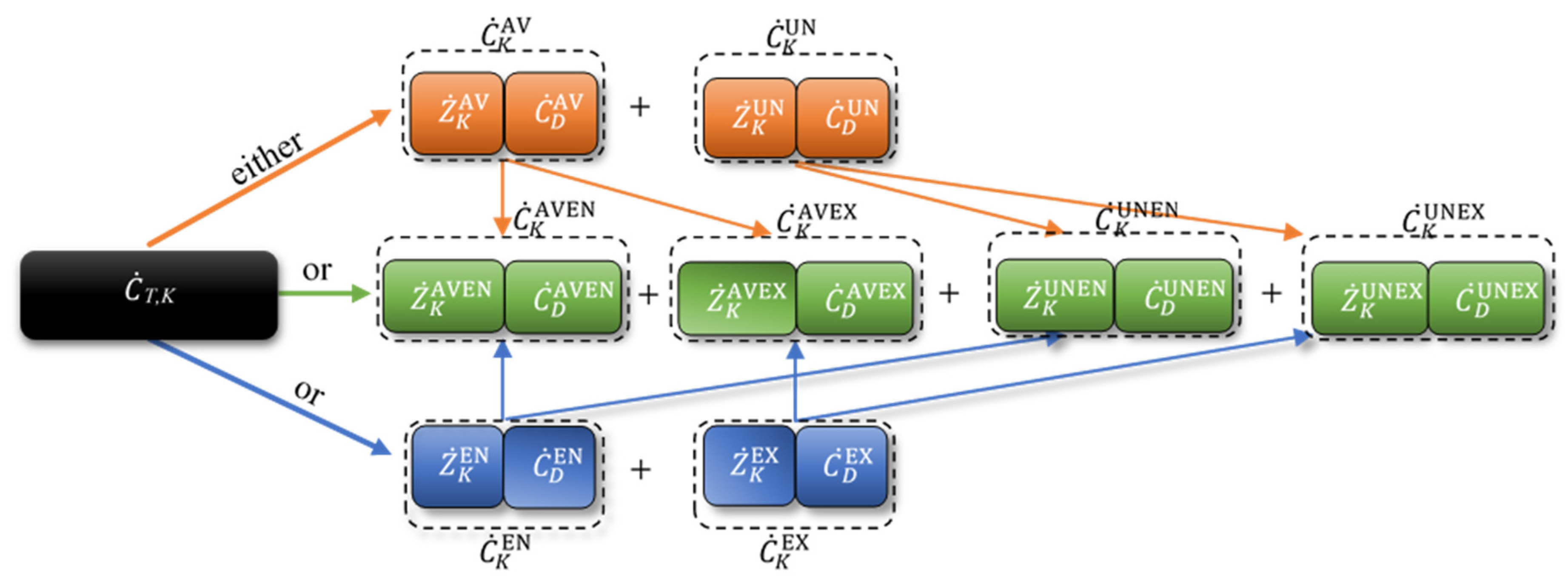
15] gives further understanding in evaluating the magnitudes and sources of exergy destruction with the consequent exergy analysis accuracy improvement. In the advanced exergy method, the endogenous/exogenous exergy destruction indicates the capability of determining the irreversibility due to system component interactions. On the other hand, the unavoidable/avoidable exergy destruction can evaluate the irreversibility to be reduced by design modifications and optimisation. This separation makes exergy contribute to the understanding and manipulation for thermal system improvement [
16].
Recently, researchers have started to apply advanced exergy methods to thermal systems, including heat pumps with different purposes. Morosuk et al. [
17] concluded that R-125, R-134a, R-22, R717, R-500, and R-407C have a comparable ratio of advanced exergy destruction splitting in a simple vapour compression cycle, and the highest exergy destruction occurs in the condenser, followed by the compressor. Meanwhile, the evaporator and the expansion valve have the highest avoidable and unavoidable endogenous exergy destruction ratio, respectively. Erbay et al. [
18] presented an advanced exergy analysis for a ground-source heat pump for drying processes. The internal operating conditions have inefficiencies on all components, except for the condenser and evaporator.
Other studies adopted the advanced exergy evaluation for ejector cooling systems and compound ejector heat pump system. Chen et al. [
19] indicated that 50% of total exergy destruction arises from the ejector, while the generator causes 25%. Zhao et al. [
20] studied parallel and series compressor–ejector arrangements showing that the highest avoidable endogenous exergy destruction ratio is reported to both compressor and ejector. Gullo [
21] applied advanced exergy analysis to transcritical R744 supermarket refrigeration systems with three arrangements: parallel compression, parallel compression with two-phase ejectors-overfed evaporators, and without two-phase ejectors. The ejector arrangement shows a total irreversibilities reduction of 9.3% and 13.5% avoidable destruction.
A new method involving advanced exergy analysis with economic restrictions (exergoeconomic analysis) has recently been adopted to optimise system performance with an accuracy not possible by conventional approaches [
14]. Sing h et al. [
16] observed that both expansion device and evaporator need optimisation for solar-assisted and conventional heat pumps for drying purposes. Ambriz-Díaz et al. [
22] considered a polygeneration plant operated by a geothermal cascade arrangement. The results indicate that the exergy destruction in the heat exchanger and in the ORC can be avoided by improving these design variables. Hepbasli et al. [
23] studied a pilot-scale air-source heat pump for food drying. They concluded that the advanced exergoeconomic analysis gives a more sensitive evaluation of inefficient components to system modification and efficiency improvement. On the other hand, cost-reducing for both heat recovery and condenser units should be improved.
According to the state-of-art revision, none of the previous studies focused on the advanced exergy and exergoeconomic analyses for advanced heat pumps, neither for these systems combined with other technologies. This work presents an advanced exergoeconomic evaluation for a new arrangement of combined ejector-solar assisted heat pump system to give a complete overview of the system’s potential. The new system arrangement is applied to data centre cooling and district heating simultaneously. It combines four promising technologies: a heat pump, ejector, PV/T panels, and waste heat recovery. The proposed system presents the novelty of employing PV/T waste heat with the evaporative condenser as a full ejector driving force, avoiding a pump’s need. The surplus PV/T generated electricity can be used to operate the heat pump, which is cooling a data centre and injecting heat in a district heating network at the same time.
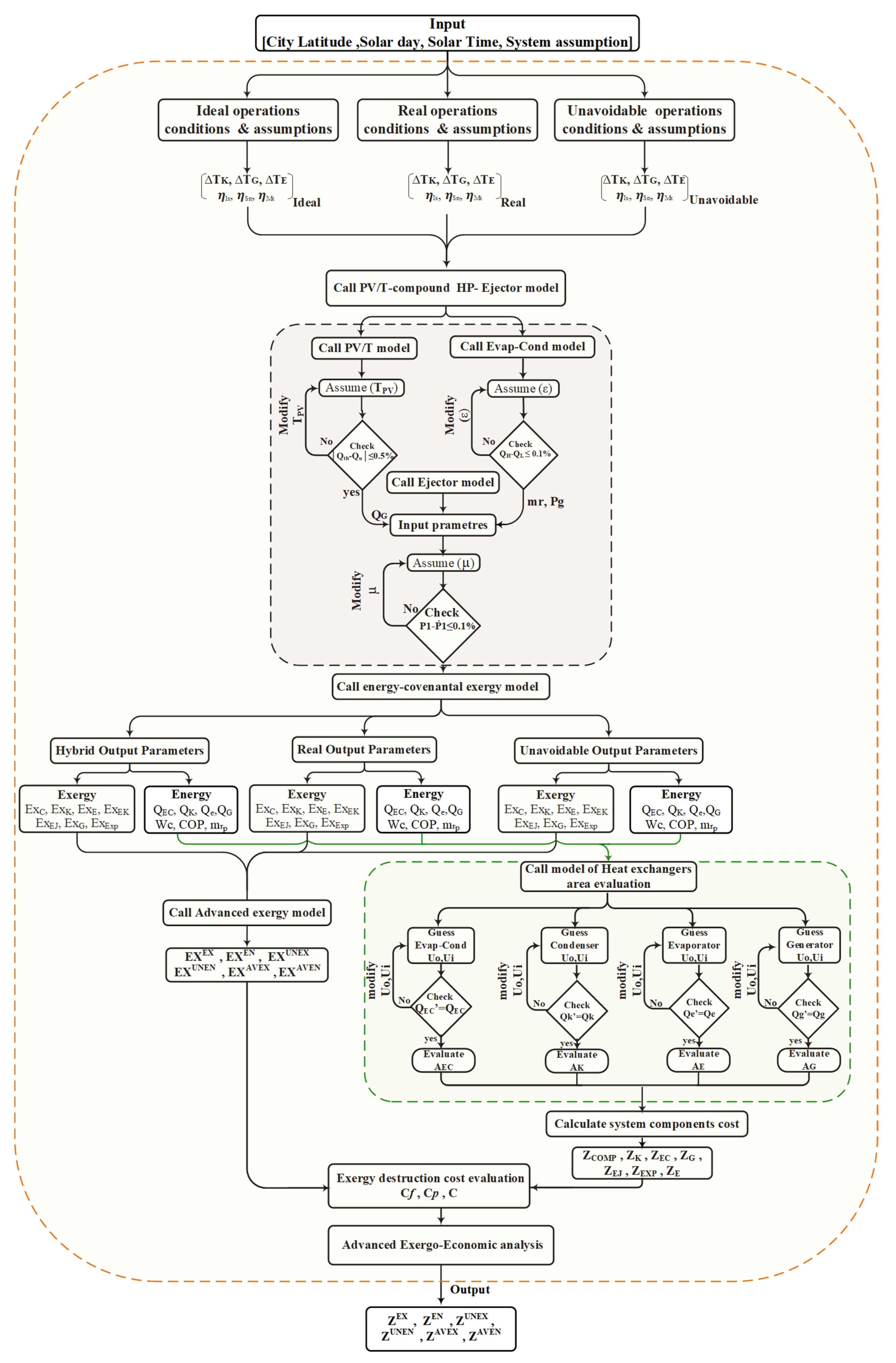
The current study’s objective is to perform conventional and advanced exergoeconomic analyses for the investigated combined ejector-solar assisted heat pump system. The exergetic destruction values and unitary exergoeconomic costs for each component were determined and discussed. This will allow us to identify the magnitude and location of the most relevant thermodynamic cost losses and provide critical insights to improve the inefficient components to be more effective and reliable.
2. System Description
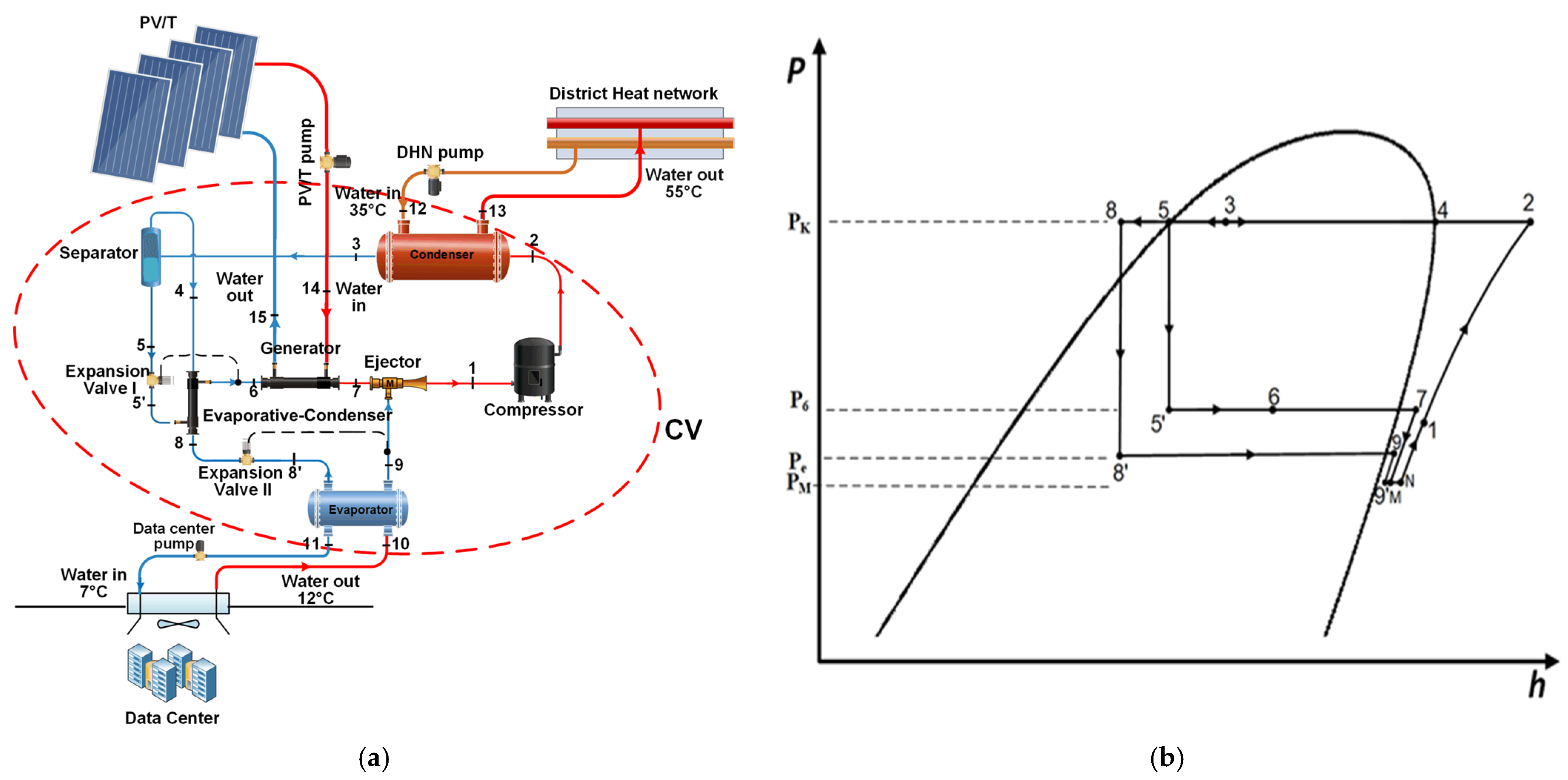
The system components layouts and pressure-enthalpy diagrams of the compound PV/T waste heat-driven ejector-heat pump system are shown in
Figure 1a,b, respectively. The compound PV/T waste heat-driven ejector-heat pump system comprises a compressor, condenser, flash tank, high-pressure expansion valves, evaporative-condenser, PV/T waste heat exchanger-generator, ejector, low-pressure expansion valve, evaporator, as well as three brine side fluid paths for PV/T-generator, evaporator, and condenser. The refrigerant has the transformations as exposed in the following paragraphs.
Superheated refrigerant enters the compressor at the intermediate pressure (State 1), and is compressed and delivered at condenser pressure. The high-pressure superheated refrigerant enters the condenser. The condensation process occurs by rejecting heat to the district heating system’s heat sink (State 3); in the next stage, the cold liquid–gas mixture goes through the flash tank to undergo an adiabatic phase separation at the condenser pressure. The refrigerant leaves the flash tank from the bottom as saturated liquid (State 5) (primary flow) and from the upper side as saturated vapour (State 4) (secondary flow). Then, the high-pressure liquid refrigerant expands through the high-pressure expansion valve in the next stage, resulting in a mixture of liquid and gas at lower pressure and lower temperatures (State 5′).
After that, the two streams of refrigerant pass through an evaporative-condenser, which is used to condense the vapour stream from the flash tank separator (secondary flow), exchanging heat with a low-temperature stream (primary flow) after the first throttling process (Expansion Valve I). The primary stream leaves the evaporative condenser in a mixture state at generator pressure (State 6). It then enters the generator, where it is evaporated by exchanging heat from the cooling water of the PV/T waste heat recovery coil. Furthermore, the bypass vapour stream’s cooling effect could be utilised at the evaporative condenser and delivered as a liquid refrigerant to the second expansion valve (the secondary flow), expanding through the low-pressure expansion valve. From this, a mixture exits at evaporator pressure (State 8′). It removes heat load from the data centre using the evaporator cooling water. It is wholly evaporated in the final stage before returning to the ejector suction nozzle (State 9) and exits superheated.
On the other hand, the refrigerant leaves the generator. After being superheated (State 7) it is shunted to the ejector’s primary nozzle, representing the most considerable refrigerant mass flow rate of the motive flow entering the nozzle and enhancing the pressure lift effect. The primary stream expands through the nozzle and exits at low pressure. It creates an evacuation force for the low-pressure vapour (secondary flow). The two streams undergo a constant pressure mixing process (State M) and introduce normal shock trains in the mixing section. Meanwhile, the pressure recovery process takes place in the diffuser section of the ejector. The mixed stream enters the compressor (State 1), where the cycle starts again.
The system is designed to cover three functions. First, the PV/T operating temperature is decreased, and the generated electric power is maximised. This waste heat is used as the generator’s heat source, acting with the vapour generated in an evaporative condenser as the ejector drive force. The second function is to absorb the data centre’s waste heat generated and maintain the indoor air conditions in the ASHRAE comfort zone. Finally, this heat is upgraded to the compressor’s functional temperature levels, specifically for district heating.
The arrangement yields high system performance due to overall exergy destruction optimisation by the ejector’s arrangement, allowing electricity saving by reducing the compressor’s pressure ratio and its irreversibility. Combining an evaporative-condenser leads to improving the system overall exergy destruction by removing the ejector’s pump (absence of pump exergy destruction). Moreover, the condenser waste heat is used in the auxiliary heat exchanger to compensate for the absence of solar intensity (overcast day conditions).
4. Results and Discussion
4.1. Conventional Exergoeconomic Analysis
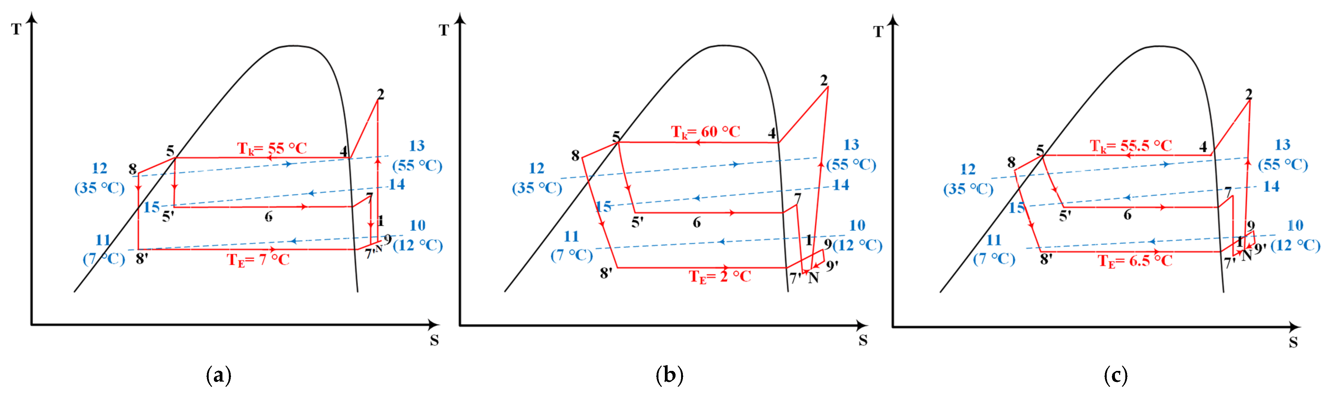
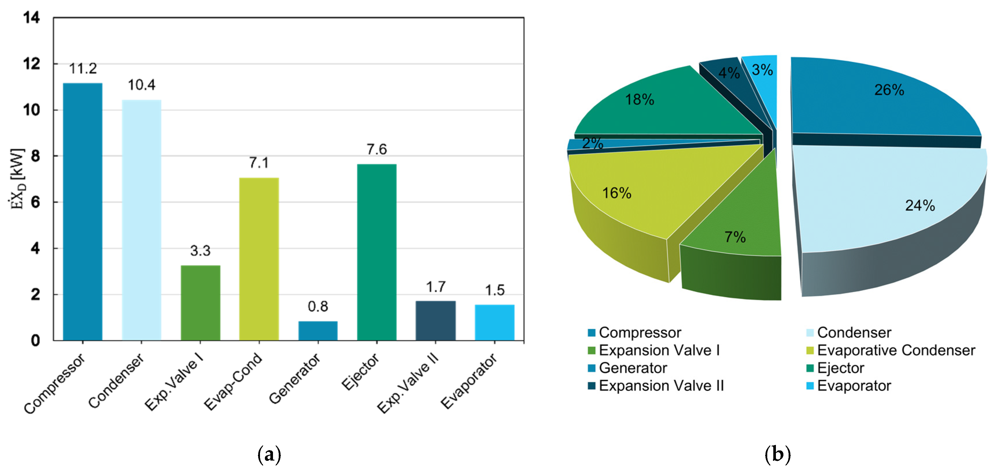
This section analyses the system exergy performance with fixed condensing and evaporating temperatures, and solar intensity,
Figure 6a. It states that the compressor represents the largest source of exergy destruction of the whole system’s exergy destruction condenser and then ejector. On the other hand, the generator presents the lowest exergy destruction source.
Figure 6b quantifies in detail the percentage of exergy destruction, compressor, 26%, followed by the condenser, 24%, and ejector exergy destruction represents 18% of the total system exergy destruction, which should be further investigated for accounting the source of irreversibility to improve in future designs. Meanwhile, both the second expansion valve and generator comprise the lowest exergy destruction percentage, 3% and 2%, respectively.
Then, the highest investment cost was for the condenser, followed by the generator, the evaporator, the compressor, and the evaporative condenser. According to the investment costs, the second expansion valve and the ejector have the lost system components cost,
Table 6.
On the other side, the compressor represents the highest cost of exergy destructions, followed by the ejector and condenser, whilst the second expansion valve had the lowest destruction costs in the system. The conventional exergoeconomic analysis showed that the second expansion valve and the generator were not significant system components concerning lowering the costs. In contrast, the compressor, the ejector, and the condenser were essential components.
4.2. Advanced Exergy Analysis
The advanced exergy analysis results are summarised in
Table 7. As a result of the endogenous exergy destruction evaluation, the condenser has the more significant exergy destruction (9.407 kW, 22% of the total) followed by evaporative-condenser (6.685 kW, 15%), and compressor (1.943 kW, 4%), meanwhile the second expansion valve represent the lowest endogenous exergy destruction of (0.4435 kW, 1%). Besides, the exogenous exergy destruction evaluation result shows that the compressor represents the highest source of exergy destruction (9.218 kW, 21% of total system exergy destruction). In comparison, the evaporator represents the lowest (0.0334 kW, 0.08%). Meanwhile, the total system endogenous exergy destruction and exogenous exergy destruction represent 53% and 47% of the total system exergy destruction, respectively. This indicates that these components’ exergy destruction is mainly due to their irreversible losses rather than the rest of the components associated with them. Therefore, priority should be given to improve each component when system optimisation is carried out. This also implies that the influence of the interactions between components is not very strong.
On the other hand, from the avoidable-unavoidable exergy destruction evaluation, the compressor represents the highest source of irreversibility, 21% of the whole system thermodynamic inefficiencies that can be avoided by further design, followed by ejector and condenser, 17% and 8%, respectively.
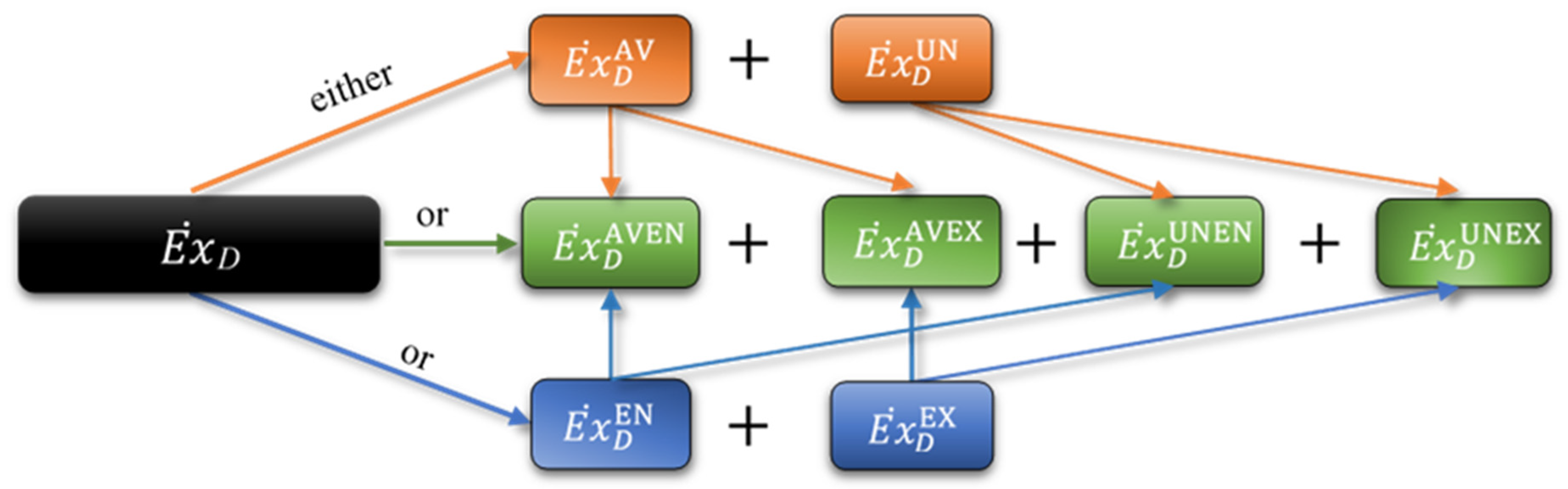
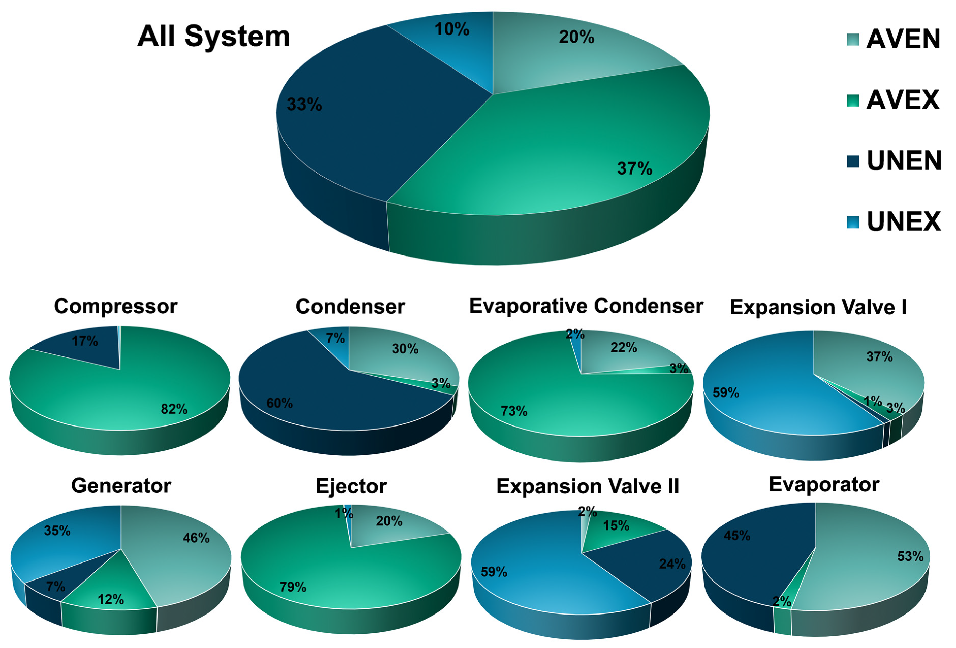
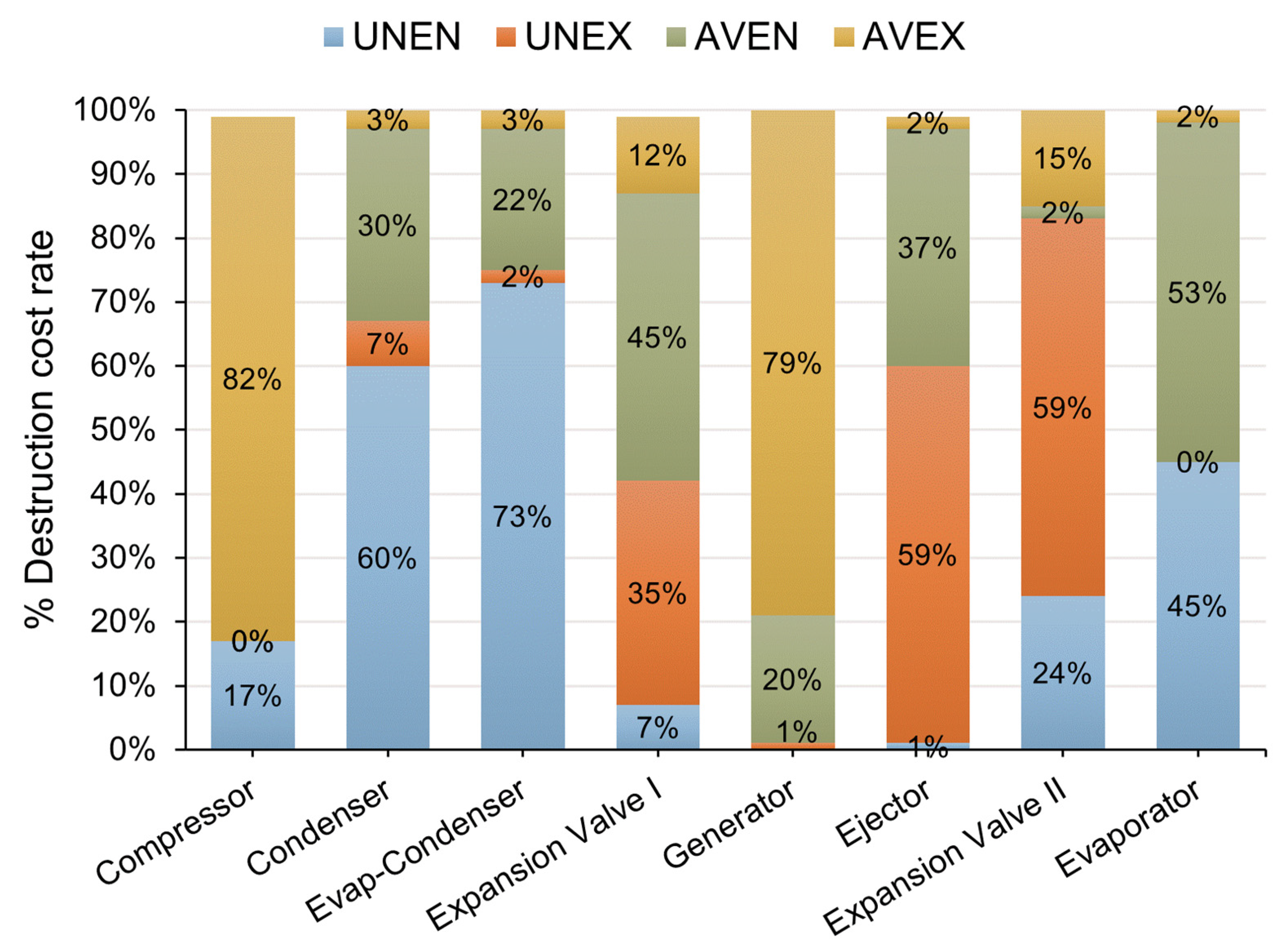
Finally, by combining the two splitting approaches, the results of this combination show that the avoidable exogenous part represents the highest exergy destruction, 37% of the total system exergy destruction,
Figure 7. Hence, the compressor represents the highest source of avoidable exogenous destruction (9.176 kW, 21% of the total system exergy destruction), followed by the ejector (6.013 kW, 14%). Meanwhile, the unavoidable endogenous part represents the second-highest exergy destruction, 33% of total system exergy destruction (
Figure 7). Hence, the condenser represents the highest source of the unavoidable endogenous part (6.3 kW, 14% of total system exergy destruction). On the other hand, the evaporator represents the lowest source of unavoidable exergy destruction.
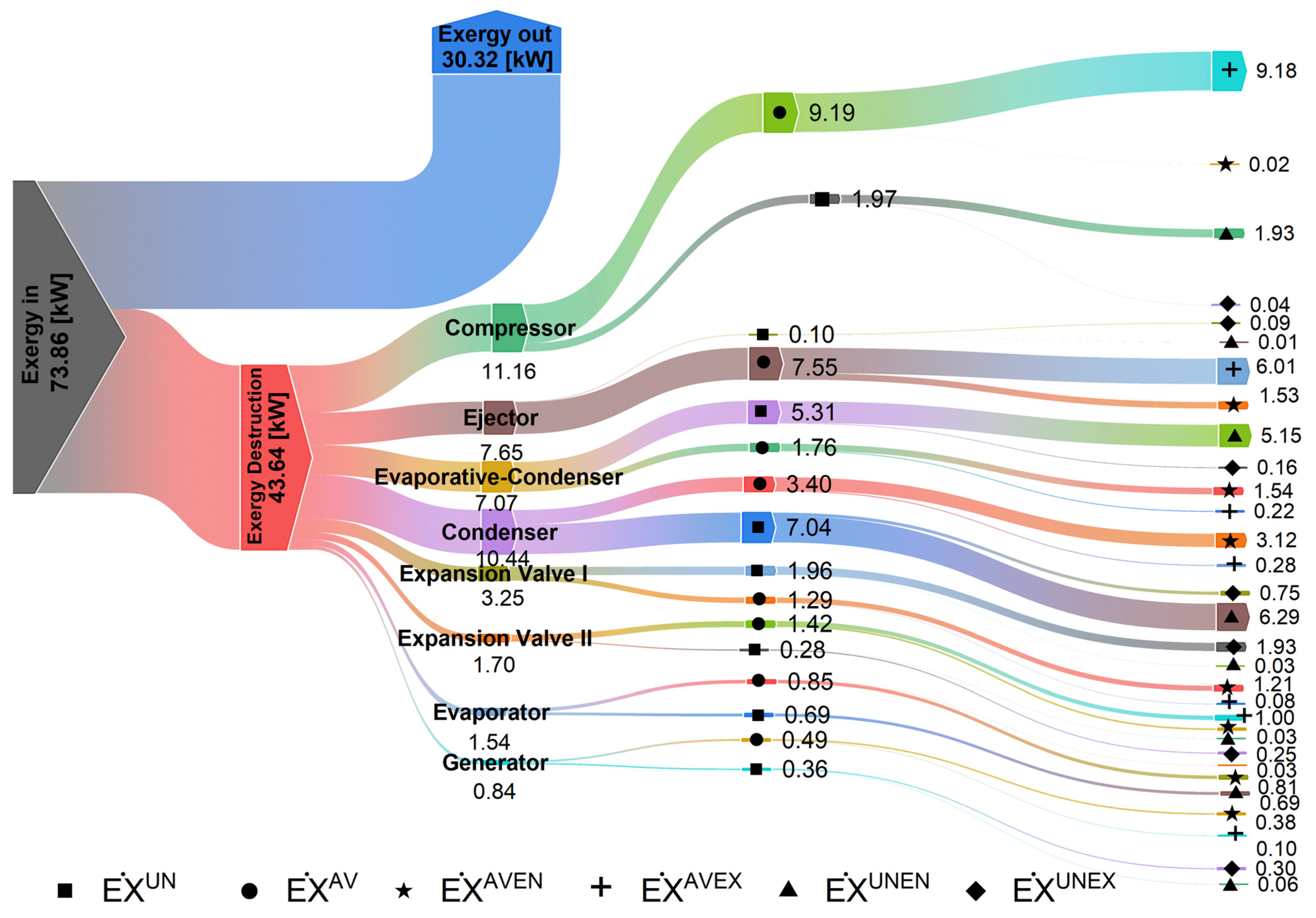
Figure 8 shows the exergy flow for the proposed system; the compressor, condenser, and ejector represent the highest avoidable exergy destruction parts for the whole system. It should give more attention by improving these components; the exergy destruction in these components can effectively decrease, leading to increased overall system COP and exergy efficiency.
4.3. Sensitivity Analysis
To better understand the components’ internal condition influences on exergy destruction, a sensitive analysis study is adopted by varying each component’s operating characteristic, setting the others. This section focuses on system avoidable exergy destruction sources because it represents a potential for improvement. According to the above previous exergy analysis, all compressors, condensers, and ejectors possess the highest performance improvement priority (represent the highest source of avoidable exergy destruction
Figure 8). So that the study focused on these components only, the rest of the components were excluded.
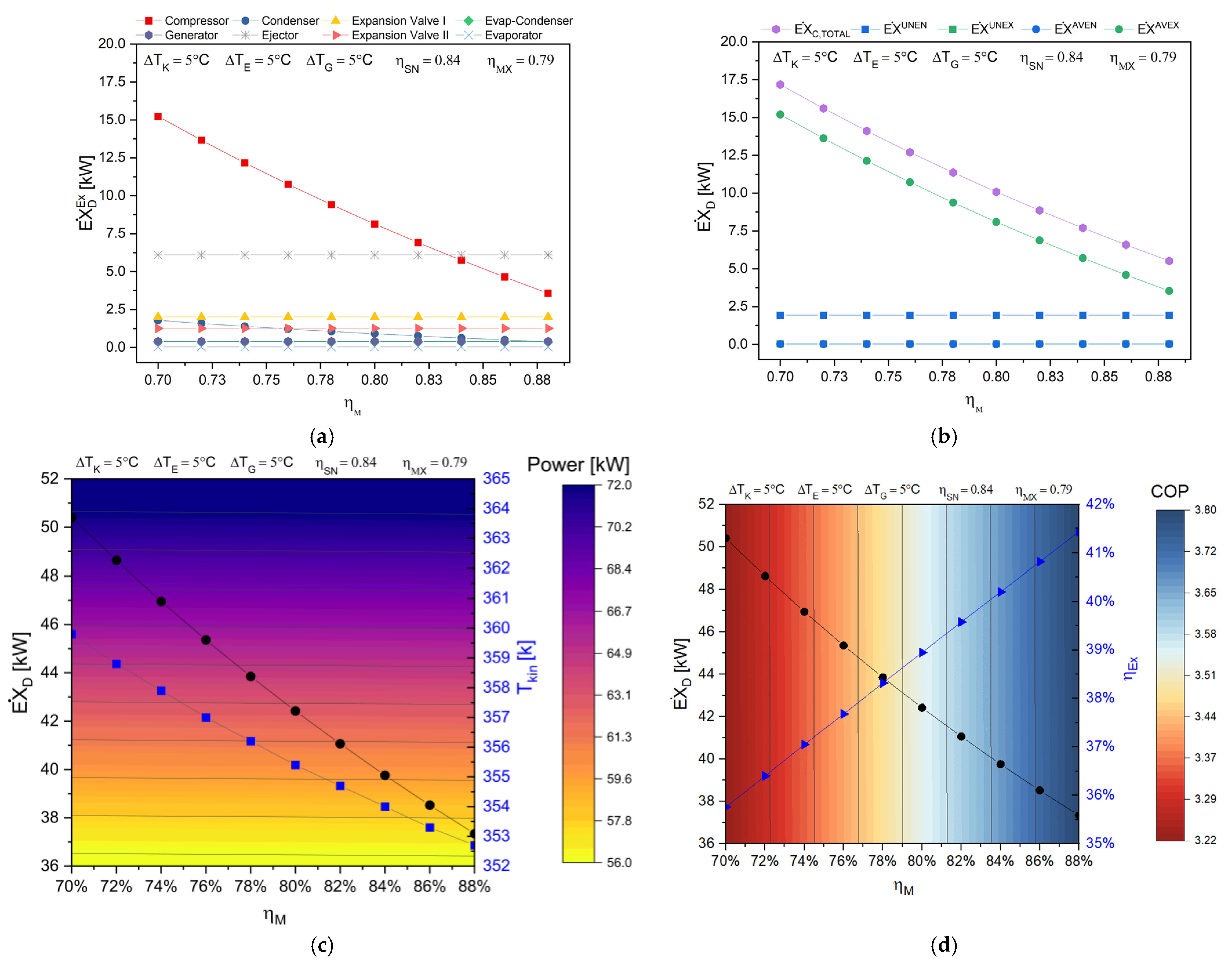
Figure 9 illustrates the effect of compressor efficiency variation on the exogenous exergy destruction of system components. The compressor exogenous exergy destruction shows a remarkable reduction with compressor efficiency increasing. Besides, none of the other components show any influences with compressor efficiency variation, just a slight reduction with condenser due to the corresponding decrease in the condenser inlet temperature (
Figure 9c).
Figure 9b evidence that the compressor avoidable exogenous exergy destruction is inversely proportional to the compressor efficiency. Meanwhile, the compressor total and system exergy destruction decrease with a compressor efficiency increase; this enhances compressor consumption power (
Figure 9c) to system exergy efficiency and COP (
Figure 9d), owing to compressor irreversibility and system reduction.
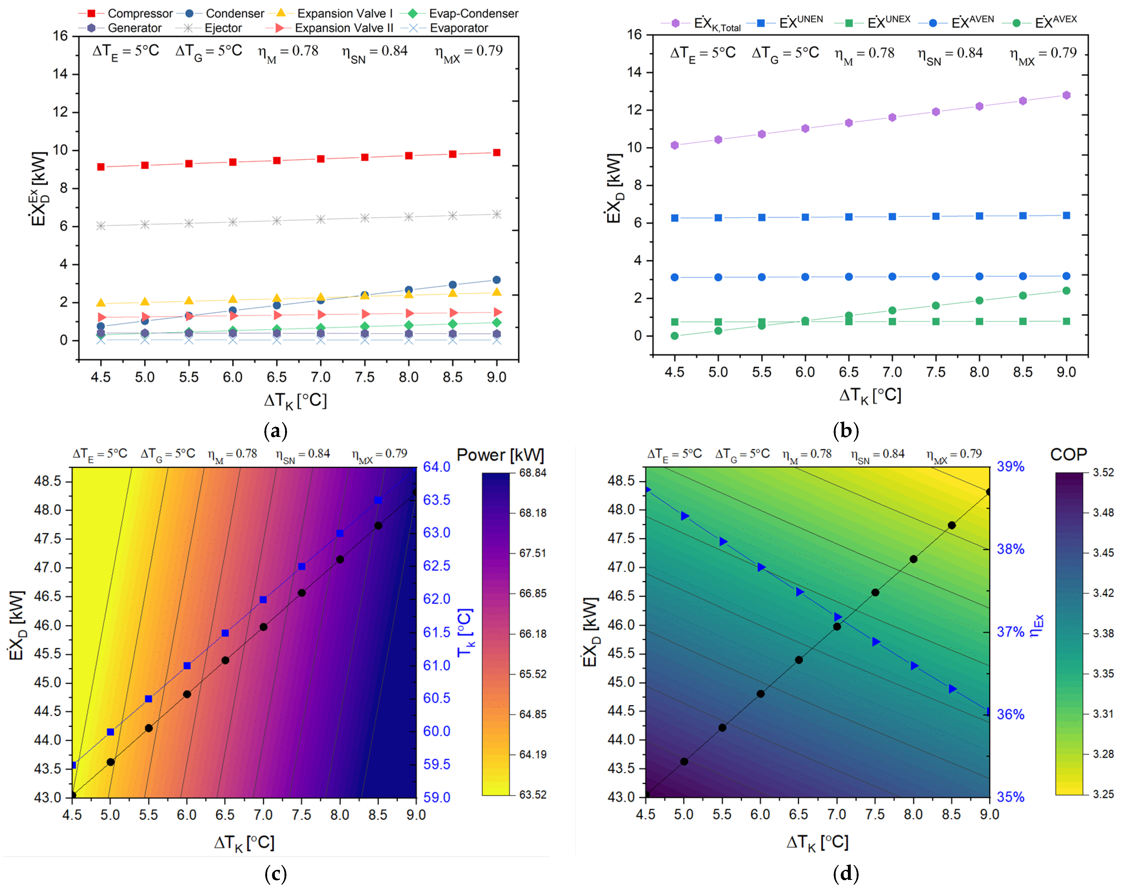
Figure 10 shows the effect of condenser glide temperature variation on system components exogenous exergy destruction. The condenser exogenous exergy destruction increases with higher glide temperature due to condenser temperature augmentation. Meanwhile, the other components are slightly increased with glide temperature variation. At constant inlet and outlet conditions of condenser cooling water, this causes the heat transfer between the condenser and its condensing medium to decrease and increase the cycle’s irreversibility.
Figure 10b shows the influence of condenser glide temperature variations on the condenser exergy destruction. The avoidable exogenous part of condenser exergy destruction is directly proportional with condenser glide temperature increasing; meanwhile, none of the other parts is influenced. Additionally, condenser glide temperature increase has the worst effect on compressor power (
Figure 10c), system exergy efficiency and system COP. As a result, the overall system exergy destruction increases at a higher condenser glide temperature (
Figure 10d).
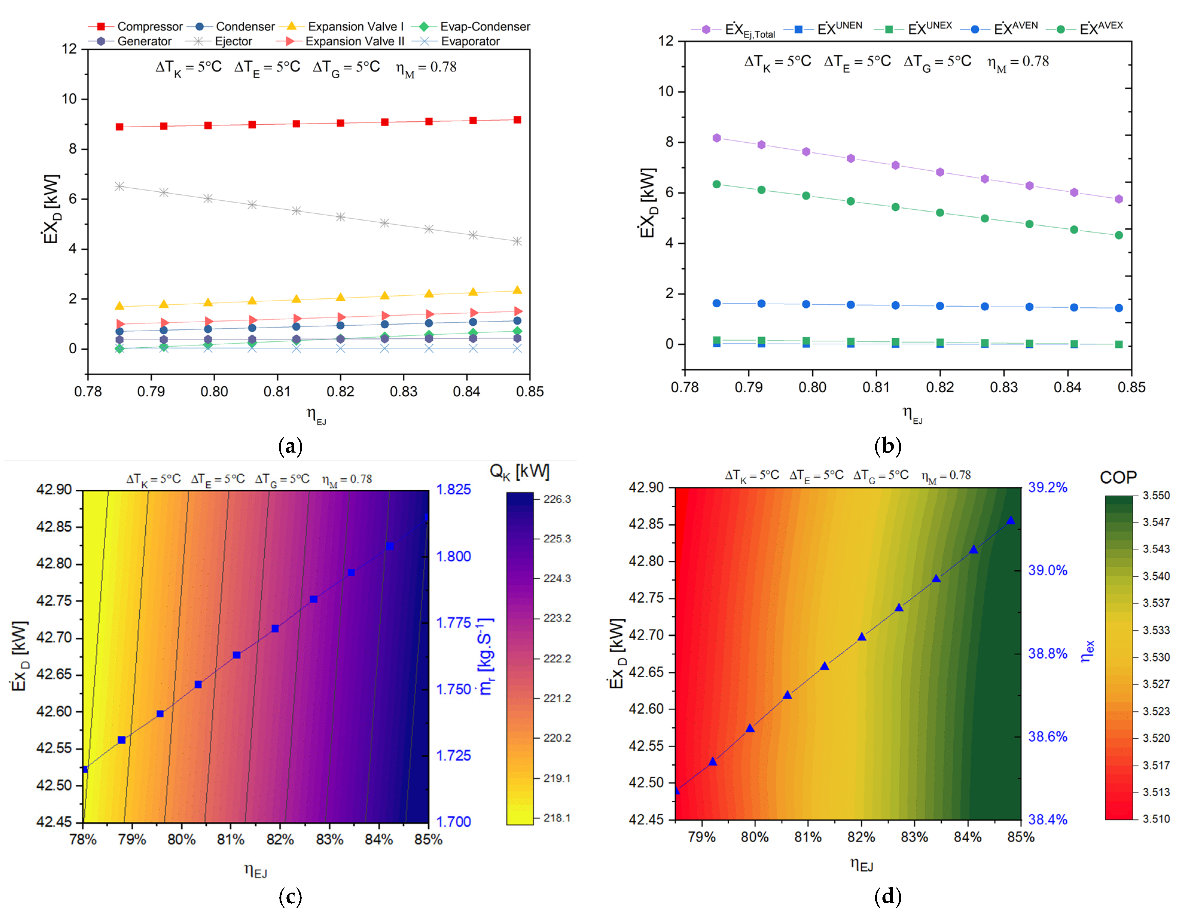
Finally,
Figure 11a illustrates the influence of ejector efficiency variation on system components exogenous exergy destruction. The ejector efficiency increasing diminishes the ejector exogenous exergy destruction. Meanwhile, the rest of the components have a negligible variation. The ejector has varied irreversibility sources, such as the nozzles flow friction irreversibility, two streams mixing irreversibility (primary and secondary flow), and compression shock waves irreversibility [
47].
On the other hand,
Figure 11b shows the influences of ejector efficiency variations on the ejector exergy destruction. The avoidable exogenous part of ejector exergy destruction decreases with ejector efficiency increasing; meanwhile, it shows a lower influence on the rest of the ejector exergy destruction. An ejector efficiency increase enhances condenser heat capacity due to a higher refrigerant mass flow rate (
Figure 11c). Meanwhile, despite the overall exergy destruction increase, both the system exergy efficiency and COP are less enhanced, increasing ejector efficiency. The overall system exergy developed increasing; the factor takes a dominant role
Figure 11d, attributed to overall system mass flow rate increases.
4.4. Advanced Exergoeconomic Analysis
From the advanced exogenous analysis,
Table 8, a significant proportion of investment destruction costs in the system are detected as exogenous (71%). Meanwhile, the avoidable destruction cost represents 62% of the overall destruction costs and avoidable-exogenous cost, 58%. In contrast, unavoidable-exogenous destruction cost was relatively low.
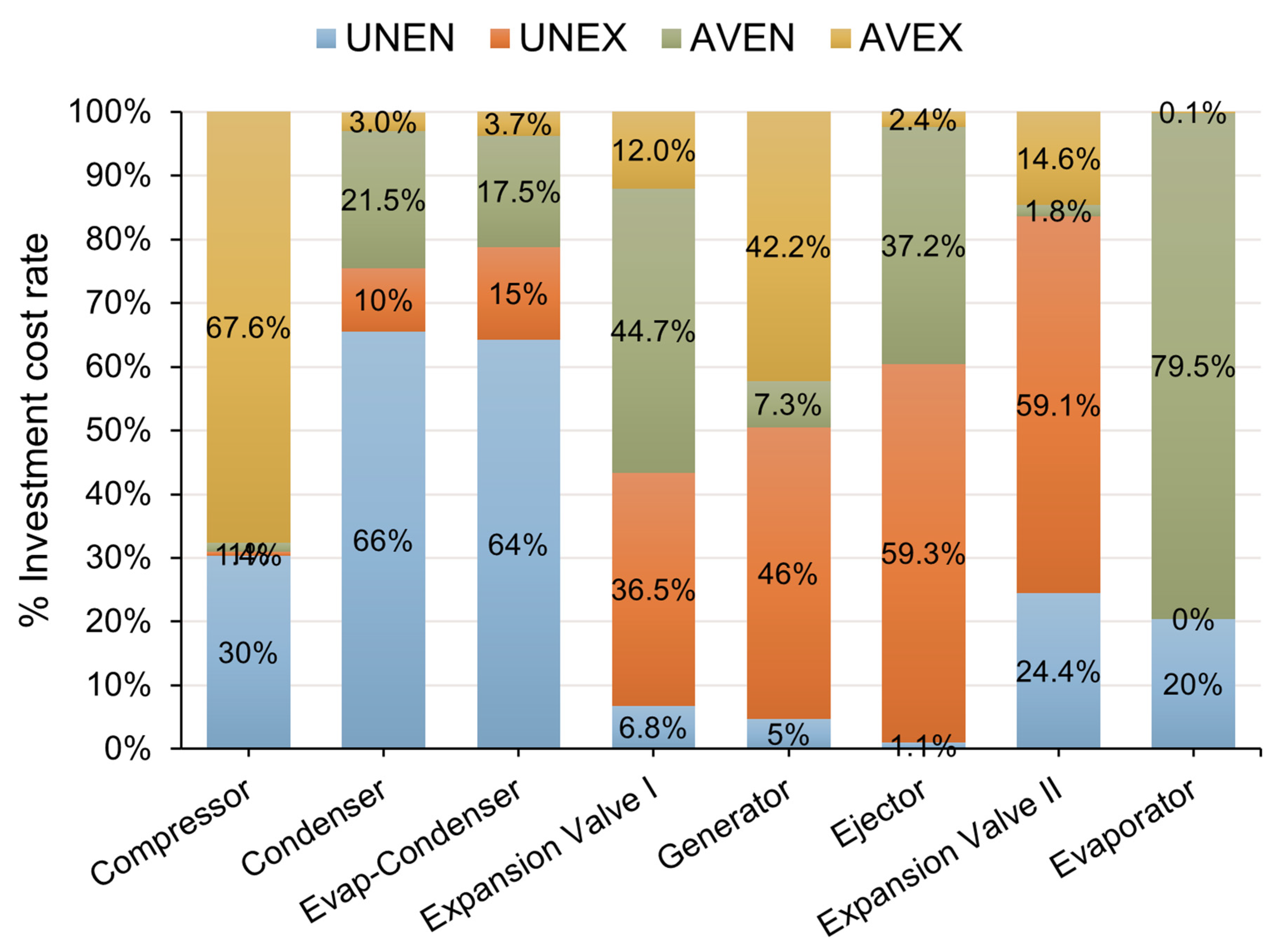
The highest exergy destruction costs are accumulated in the compressor, 41.9% of the total exergy destruction in avoidable exogenous. The generator follows it. A substantial proportion of the exergy destruction cost is avoidable-exogenous, 15.1% of the overall system investment costs (approximately 79% of the generator exergy destruction cost,
Figure 12). The third significant exergy destruction cost is accumulated in a condenser. Still, in this case, it is unavoidable-endogenous, 8.4% of the overall system investment costs (approximately 60% of the condenser exergy destruction cost,
Figure 12). The two parts of avoidable exergy cost (AVEN and AVEX) components are 3.9% and 0.2% of overall system investment costs. Consequently, the second expansion valve exergy destruction costs represent a narrow share of the destruction costs (0.7%). Therefore, improvements concentrated on the second expansion valve destructions would have limited importance and investment costs.
From
Table 9, 51% of the system costs are unavoidable; meanwhile, 29% is avoidable exogenous and 20% is avoidable endogenous. In system components cost comparison, the highest cost comes from the condenser (30%), followed by the compressor (26.4%) and generator (24%), and both expansion valve represents the lowest components cost (below 1%).
From
Figure 13, 68% of compressor cost is avoidable, and according to
Table 9, the compressor has an exergoeconomic factor (f) of 19%. It indicates that the exergy destruction cost has a marked influence on total compressor cost; therefore, it should improve the compressor performance. For the generator, 43% of the investigated cost is avoidable with an exergoeconomic factor of 67%; this indicates that the construction cost significantly influences total generator cost. The same conclusion as the compressor can be drafted.
In the same context, the ejector has the lowest exergoeconomic factor (0.1%), and it should be getting more attention to reduce the irreversibility by design improvement. On the contrary, the evaporator has the highest exergoeconomic factor (94%), giving more about evaporator construction for improving.
On the other hand, approximately half of the total investment costs (49%) were avoidable, and 29% of the system exergy destruction is exogenous avoidable, larger than endogenous avoidable exergy destruction. It indicates that the interaction between components is strong, and the exergy destruction of these components are mainly due to irreversible losses of components associated with them.


 and
and 


