Article

Production of Agricultural Biogas with the Use of a Hydrodynamic Mixing System of a Polydisperse Substrate in a Reactor with an Adhesive Bed

1
Department of Applied Mathematics and Computer Science, University of Life Sciences in Lublin, 20-033 Lublin, Poland
2
Department of Pomology, Nursery and Enology, University of Life Sciences in Lublin, 20-033 Lublin, Poland
3
Department of Energy, Lviv National Agrarian University, 1 V. Velykoho Street, 80381 Lviv-Dubliany, Ukraine
4
Department of Technology, Institute of Energy and Technical Safety, Jacob of Paradyz University, 52 Chopina Street, 66-400 Gorzow Wielkopolski, Poland
5
Institute of Technology and Life Sciences—National Research Institute, Falenty, Al. Hrabska 3, 05-090 Raszyn, Poland
6
Department of Renewable Energy, 67 Biskupinska Street, 60-463 Poznan, Poland
*
Author to whom correspondence should be addressed.
Submission received: 28 April 2021 / Revised: 1 June 2021 / Accepted: 8 June 2021 / Published: 14 June 2021
(This article belongs to the Special Issue Energy Crops Production in Central and Eastern Europe)

Abstract

:
The properties, types, and physical and chemical aspects of pig slurry used in the fermentation process were presented. Characterization of the pig slurry microflora for a controlled biogas production process was performed. A pilot biogas treatment installation was presented on the example of a farm with 1100 Dan Bred fatteners kept in a grate system. The research was carried out to measure the biogas flow rate resulting from the reference pressure in the fermentor. An independent assessment of the amount of biogas and the pressure drop in the skeletal deposit was carried out. The basis for assessing the hydrodynamics of gas flow through the adhesive bed is the flow characteristic, which results from the pressure that forces this flow. In each case, the determination of this characteristic consists in determining the influence of the biogas stream on the value of this overpressure, equivalent to the pressure drop (it is tantamount to determining the total biogas flow resistance through the adhesive bed). The results of the measurements indicate the practical application of pig slurry-a substrate in a polydisperse system for the production of agricultural biogas in the context of renewable energies. The article indicates that the ferment was periodically mixed during the day, together with the fermentation of the ferment with fresh substrate. The tests were conducted for 49 days, thus demonstrating that it is more advantageous to mix the ferment hydrodynamically, obtaining a CH4 level of about 80%.

1. Introduction

As a result of the litter-free animal husbandry system on farms, slurry is produced, which is a valuable source of fertilizer. However, its use in excess or in inappropriate agrotechnical periods can seriously pollute the environment [1]. The main environmental hazards resulting from large-scale animal husbandry and related slurry production are as follows [2]:
-
Water pollution: soil overfertilization and outflow from fields to groundwaters and surface waters;
-
Eutrophication: overfertilization of inland and sea waters (algal blooms, reduction of biodiversity and modification of aquatic ecosystems, loss of benthic fauna and the lack of oxygen);
-
Microbiological contamination: pathogenic microorganisms contained in slurry pose a serious sanitary threat; Staphylococcus sp., faecal streptococci, Escherichia coli, rhusiopathia suum, tuberculosis mycobacteria, pathogenic streptococci, foot-and-mouth disease virus, fungi and larvae, and eggs of parasitic worms (e.g., tapeworms) are considered the most significant;
-
Indirect and secondary impact on the formation of acid rain (emission of nitrogen oxides and sulfur oxides) and increase of the greenhouse effect (emission of greenhouse gases damaging the ozone layer) [3].
First of all, the latter point refers to the infiltration of nitrogen into soils, which is found in large quantities in slurry. The excessive amount of nitrogen in the soil flows, in the form of nitrates, into the groundwater and contaminates it [4,5]. Additionally, a high inflow of ammonia poses a direct risk of eutrophication of surface waters in areas of intensive animal exploitation [6,7,8]. Heavy metals are another threat because, as proved by studies [9], high concentrations of copper and zinc may occur in soils fertilized with slurry. The storage of animal manure also leads to gaseous emissions [10,11]. The emitted gases comprise, among others, sulfur and nitrogen oxides that cause acid rain, photochemical smog and water eutrophication [12]. Farm animal husbandry also generates greenhouse gas emissions, e.g., methane produced during the digestion of feed, especially by ruminants, and during manure storage [13]. Another greenhouse gas with a higher environmental impact due to its persistence in the atmosphere that damages the ozone layer is nitrous oxide, which is mainly released during the use of manure. Another disadvantage of slurry is its high water content, which results in high costs of storage and transport to fields. These factors limit the intensive livestock production in favor of sustainable agriculture that will certainly not replace the current and anticipated demand for meat [14].
In order to protect the natural environment, many solutions that aim at proper slurry management are proposed [15]. One of the key methods of animal manure management is the methane fermentation of manure in agricultural biogas plants. The neutralization of slurry as a substrate by methane fermentation additionally results in the obtainment of energy and fertilizer with better parameters compared to raw slurry [16,17].
A common technology employed to dispose of slurry is the methane fermentation of slurry in agricultural biogas plants. This technology, however, generates high investment costs [1]. Additionally, a large volume of this substrate and low content of organic matter hinders the rise of temperature of this process [18,19,20]. The cost of heating energy and the low biogas efficiency of the substrate make it economically unprofitable [1]. The slurry disposal by methane fermentation is only profitable for large-scale systems [21]. Studies conducted by Deng et al. [22] show the soundness of slurry separation, which makes it possible to reduce costs of heating and to obtain greater biogas efficiency through a faster rate of degradation of this substrate. The studies have also proven that the separation reduces the volume of digester by two thirds [23]. Due to the high hydration of slurry, its application as mono-substratum brings little economic yield to this process [24]. Therefore, this process requires the addition of other substrates that increase the content of dry organic matter of the fermentation mixture [25].
Pig slurry is commonly used as fertilizer due to its low capital expenditures. Pig slurry is commonly used as a fertilizer due to low investment costs, taking into account its management for agricultural purposes in the area of the farm. However, it is preferable to use pig slurry to produce biogas, namely, to convert it as a digestate product necessary to fertilize the soil due to the absence of odors. The studies [1,2,3,4,5,6,7,8,9,10,11,12,13] show that its improper application pollutes soil and water. It also leads to emissions of odorous and greenhouse gases [26,27]. In view of the existing risks, it is recommended to manage pig slurry by methane fermentation. Numerous properties of pig slurry facilitate methane fermentation, e.g., the content of basic macro- and microelements that promote the development of bacterial microflora or the presence of anaerobic microorganisms.

1.1. Properties of Pig Slurry Used in the Fermentation Process

Slurry is a natural liquid manure, a mixture of fecesfeces, urine and water that may be successfully used in the methane fermentation process in a vast number of agricultural biogas plants. Urine is 96% water and contains inorganic and organic nitrogen compounds, vitamins, hormones and enzymes. Feces comprises feed residues (digested and undigested), body secretions, and bacteria and their metabolic products [2,28]. This is mainly supported by the presence of macro- and microelements. These components enable the development and functioning of anaerobic microorganisms responsible for the process. The content of methane in biogas is indicated by the presence of proteins, fats and carbohydrates. It is also important to maintain the carbon/nitrogen ratio that allows for the proper decomposition of organic material. The excessive amount of nitrogen emits ammonia that is an inhibitor of the process [29,30,31].

1.1.1. Types of Slurry

The reference books [2] include various definitions of slurry and numerous frequently divergent data on its quantity and composition. Generally, slurry is assumed to be a liquid product produced during the litter-free animal husbandry; it is a mixture of animal feces, both solid and liquid in natural proportions, that additionally contains process water used to rinse slurry and coming from leakages of animal watering equipment [28,32]. Depending on animal species, there is cattle, pig and poultry slurry, and this latter type is discharged from dry farms as so-called litter. Due to the amount of water in manure, slurry is divided into dense (over 8% of dry matter) and thin (less than 8% of dry matter). There is also diluted slurry, in which process water exceeds 20% of the volume of manure and the dry matter content is less than 8%. Slurry is also divided with respect to the content of admixtures (e.g., slurry, sewage from farms or from outside facilities). In this case, it is divided into complete slurry (without any admixtures) and incomplete slurry (mixed with at least one of the aforesaid admixtures) is distinguished [3].

1.1.2. Physical and Chemical Aspects of Slurry

The amount and composition of slurry is significantly influenced by species, age, efficiency, animal feeding method, slurry drainage and storage method, water consumption on farms and weather conditions. In view of its further use, the most significant properties of slurry are the content of nitrogen and phosphorus. Moreover, its parameters are also determined by the content of organic and inorganic substances, particle size and pH. All these factors are essential for choosing an appropriate method of slurry preparation or treatment depending on its further use. The most important criterion that determines properties of slurry is the animal species due to the structure and functioning of its digestive system. Pigs are monogastric animals [1,33].

1.2. Slurry Microflora

The survival of the tested microorganisms in slurry depends on a vast number of factors, frequently strongly interrelated. The most important are as follows [34]: temperature, animal species from which slurry originates (slurry type), dry matter and organic dry matter content, reaction, presence of antagonistic natural microflora, initial quantity of tested microorganisms, properties of given serotype and strain, abundance of slurry in nutrients, dissolved gaseous substances and REDOX potential.
The slurry microflora includes viruses, bacteria, fungi and parasites. Viruses—components of particular epidemiological and epizootic significance—get into slurry mainly with animal feces [35,36]. Slurry also contains viruses of Aujeszky’s disease that survive (3 ÷ 15) weeks, viruses of Born’s disease-about 22 days, viruses of Marek’s disease-about 7 days, viruses of Teschen disease (3 ÷ 25) days, viruses of African swine fever (6 ÷ 160) days and viruses of foot-and-mouth disease (21 ÷ 103) days [36]. Bacteria are the dominant component in the set of organisms living in slurry. Both saprophytic and pathogenic bacteria are present [37]. The total number of aerobic and relatively anaerobic bacteria is (109 ÷ 1010) colony-forming units (CFU) in 1 cm3 of slurry [35]. Slurry from a healthy flock is dominated by a natural intestinal microflora, characterized by moderate or insignificant virulence [38]. However, the dominant role is played by microorganisms brought into slurry with feces. Bacteria most often isolated from slurry are Enterobacteriaceae and enterocococci [35]. The dominant role is played by Escherichia coli, which is (105 ÷ 106) CFU × cm−3 and rods of Salmonella in the number of 102 CFU × cm−3 [35,37]. Any microorganism may be present in slurry that has been excreted from the animal’s body together with manure. Therefore, Listeria monocytogenes, Yersinia enterocolitica and Campylobacter are sporadically found in this substrate. The survival time of these microorganisms in slurry is similar to their survival time in slurry water and slightly depends on temperature. Yersinia enterocolitica bacteria survive in the suspension for about 10 days, and Campylobacter bacteria for 3 days [39].
Among the fungi colonising slurry, yeast-like fungi predominate, while mould fungi are less numerous and mainly represented by the following types of fungi [40]: Mucor, Penicillium, Aspergillus and Botryotrichum. Pathogenic fungi are relatively rarely found in slurry [36]. The presence of parasites and their eggs and oocysts in slurry also plays a negative role [35]. These organisms cause invasive diseases [37]. The pig slurry contains protozoa of the genera Eimeria and Balantidium and worms of the genus Ascaris and their eggs, as well as worms of Oesophagostomum spp. Eggs of roundworms in slurry stored at 8 °C retain their invasiveness for (75 ÷ 85) days, while at (18 ÷ 26) °C they survive for about 28 days. On the other hand, mature members of the armed tapeworm survive in pig manure at 8 °C for 76 days [36,41,42]. A significant role is also played by protozoa of the genera Giardia and Cryptosporidium, showing partial resistance to the fermentation (hygienization) process of slurry [37].
The list of bacteria, the appearance of which in slurry may pose a serious risk to humans and animals under European conditions, includes as follows [40]: Brucella spp., Chlamydia spp., E. coli (antibiotic-resistant enteropathogenic strains), Leptospira spp., Rickettsia spp., Salmonella spp., Treponema hyodysenteriae, Bacillus anthracis, Erysipelothrix rhusio pathiae and Mycobacterium spp. (among others M. tuberculosis, M. bovis and M. aviumcomplex). Their presence and number depend on environmental factors, the animal species from which slurry comes and its physical and chemical properties and composition [36].
The intensive livestock production is a source of slurry, liquid manure or manure that is difficult to dispose of and pollutes the environment [43]. The technology of waste utilization by methane fermentation is an excellent way to neutralize the waste with simultaneous energy generation [44]. Livestock farming is responsible for nearly one fifth of global greenhouse gas emissions. Methane emissions from cow breeding are more than 18 times higher than from fattening pigs [45]. According to Podkówka [46], the manure monofermentation is still not very effective since this raw material contains only about 8% of dry matter and 75% of dry organic matter in dry matter. The carbon/nitrogen (C:N) ratio in cattle slurry is too low and equals 6.8:1 [46].
This problem was taken up by the Institute of Technology and Life Sciences, National Research Institute in Poland, specifically the Renewable Energy Department in Poznań, a monosubstrate reactor for methane slurry fermentation was developed for this purpose [47]. The design and construction of the monosubstrate model of a flow biogas reactor was carried out on the basis of the invention [48]. A biogas plant [49] was implemented on the farm in Ocieszyn as part of the project BIOGAS&EE financed by the National Centre for Research and Development implemented in the BIOSTRATEG 1 programme.
The aim of the research presented in the article is to evaluate agricultural biogas produced in the process of mesophilic methane fermentation from a polydisperse substrate, using an adhesive bed placed in the fermentor. An attempt was made to determine the hydrodynamic conditions for:
-
Immobilization, which allows to increase the active surface for the flora of fermenting bacteria;
-
Polydisperse substrate mixing system.
thus influencing the achievement of high CH4 content in biogas and stable production of the amount of biogas.
The following criteria were adopted for the evaluation of agricultural biogas:
-
Biogas composition;
-
Course of changes in the average daily gas stream;
-
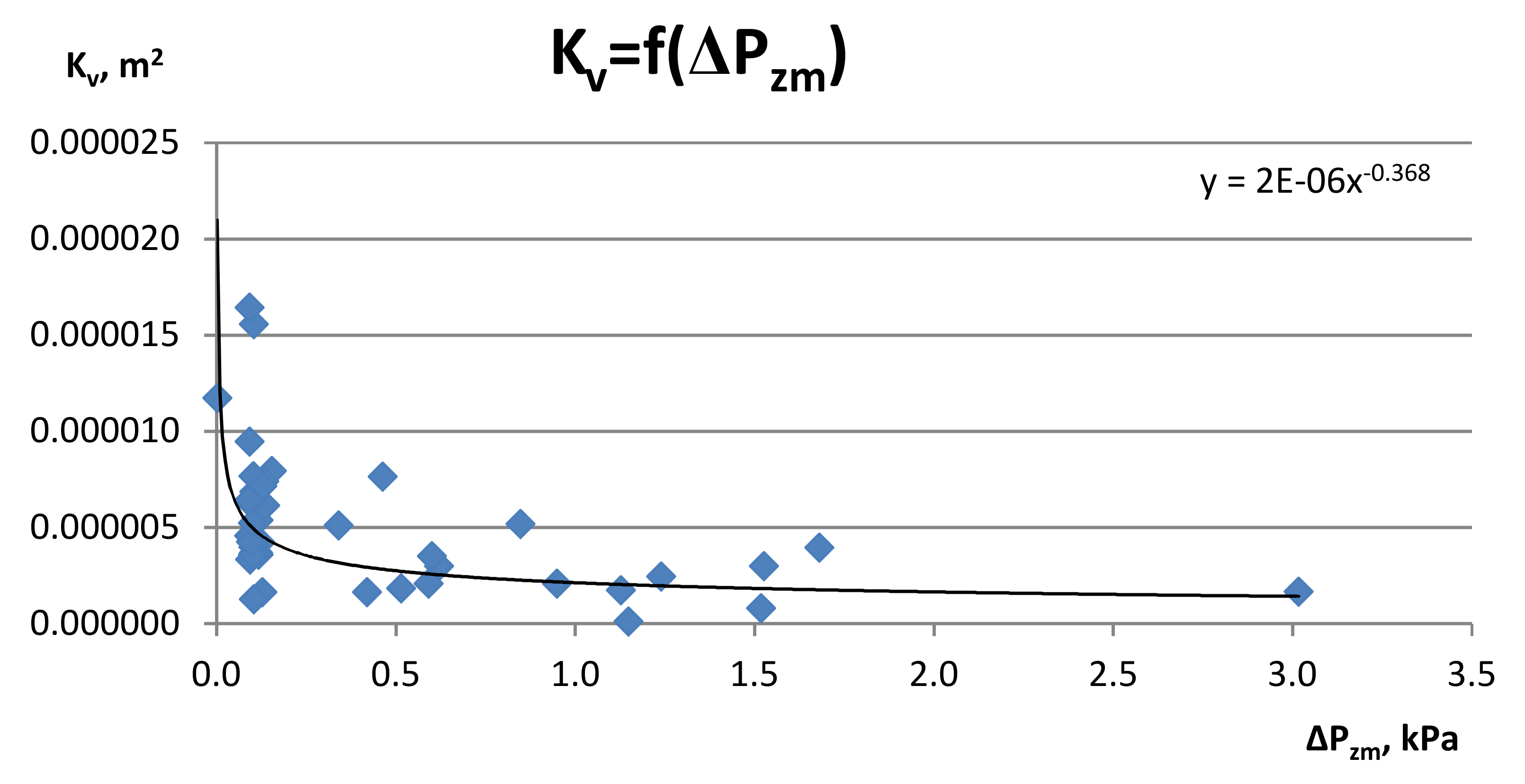
Gas permeability characteristics resulting from the pressure forcing this flow;
-
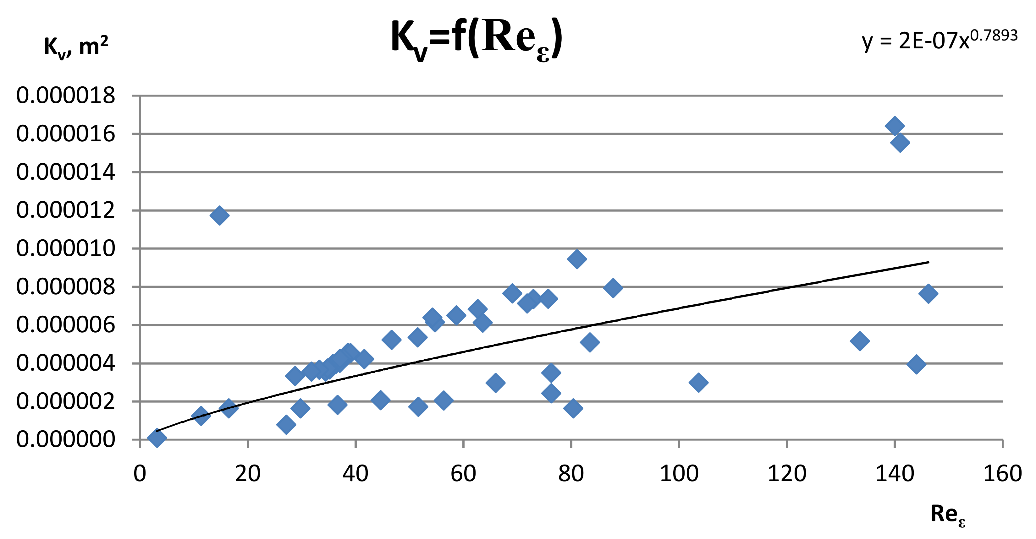
The dependence of the Reynolds number on the gas permeability coefficient.

2. Materials and Methods
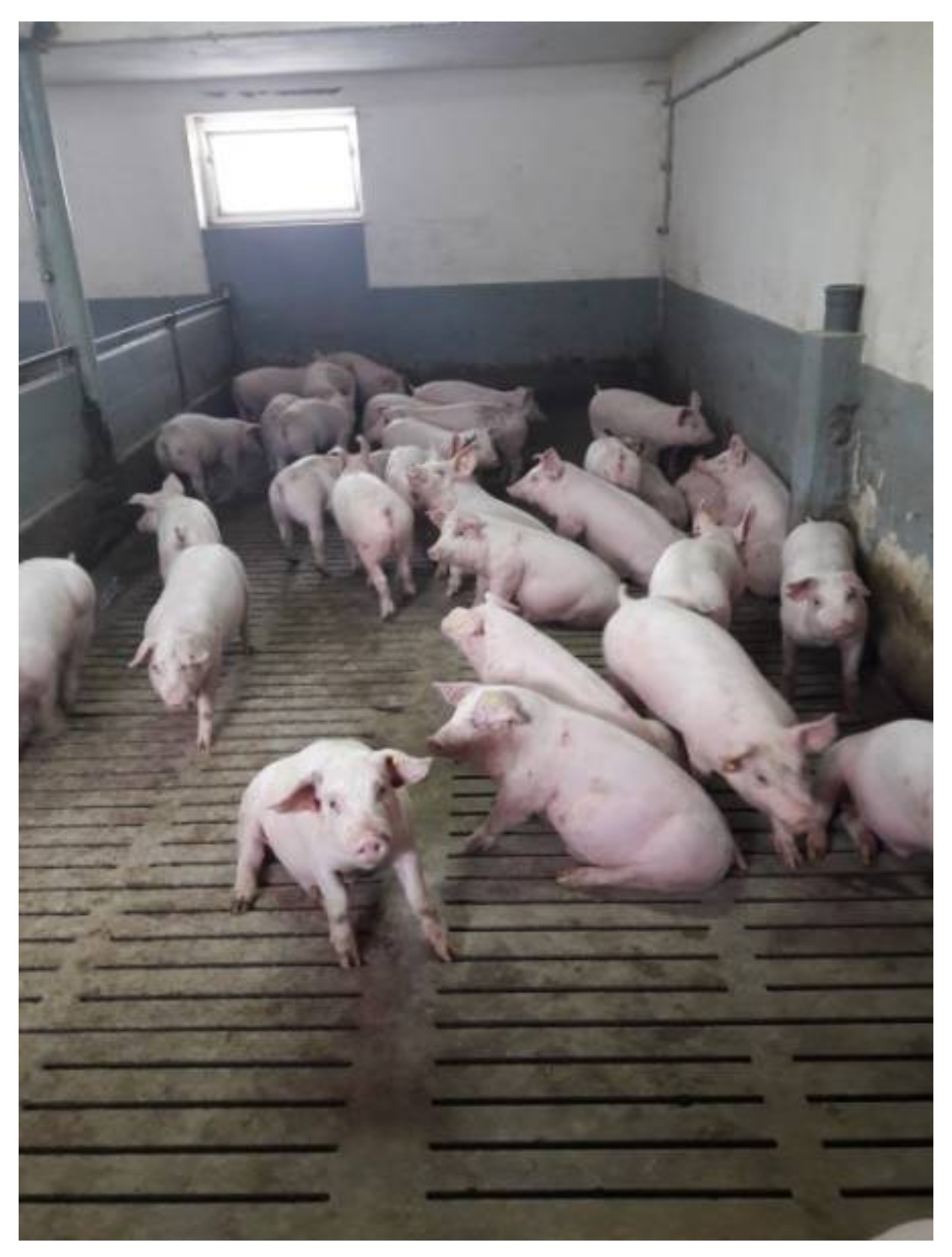
2.1. Pig Slurry

The research material was a substrate in the form of pig slurry from a farm with 1100 Dan Bred fatteners [50] kept in a grate system Figure 1.
The way of feeding pigs based on the balance of ingredients Table 1 and nutrition program Table 2 basically determines the production of the substrate (pig manure) Table 3. The applied nutrition in the form of Superconcentrate 600 plus is a feed mixture composed of post-extraction meal: soybean meal, rapeseed meal, calcium carbonate, phosphate, herbal mixture, supplementary for fattening pigs over 30 kg with the addition of phytobiotic and acidifier-content of analytical ingredients in 1 kg [51].

2.2. Model of a Monosubstrate, Flow Biogas Reactor-Research Position

The design and construction of a monosubstrate, flow biogas reactor model was carried out on the basis of the invention [52].
The subject of the invention [53] is shown in the embodiment in Figure 2, which is a schematic illustration of a fermentor.
The fermenter, whose cylindrical part is situated vertically, contains packing in the form of vertical tubes 1, with rough surfaces, made of plastic. In the top part of the fermenter there is a common stub pipe 2, via which the fresh substrate is fed, the pig slurry/liquid manure and the fermenting mass. The biogas outlet stub pipe 3 is next to it; it is connected with a pipeline via a blower 4, a gas dehydrating valve 5, a biogas inlet stub pipe 6 and a bubbler (barbotage device) 7, situated at the bottom of the fermenter. The bubbler (barbotage device) is situated horizontally near the bottom of the fermenter. The vertical tubes 1, which increase the active surface for the fermentation bacteria flora, are situated inside the heating coil 8 (Figure 3). The heating coil is connected with a water pump 9 and a heat exchanger 10, which form a closed-loop water circuit/cycle.
In the lower part of the fermenter Figure 4 there is a fermentation mass outlet stub pipe 11, which, via the fermentation mass pump 12, is connected with a common stub pipe 2 feeding the fresh substrate, the liquid manure and the fermenting mass to the fermenter.
The external surfaces of the fermenter walls/shell are covered by a layer of thermal insulation 13. The fermenter has a safety valve 14; a main outlet stub pipe 15 for post-fermentation residue connected with a pump 16 of the post-fermentation residue; and a biogas outlet stub pipe 17, via which the gas is routed for further use.
The fermenter is filled in via stub pipe 2 with slurry/liquid manure in an automatic cycle, ensuring vertical migration of the bio-fermenting fraction through the entire tank. Periodically, the post-fermentation residue combined with the slurry also goes through this stub pipe. A portion of the biogas, present in the gas space of the fermenter, is transferred to the bubbler (barbotage device) and then, in the form of bubbles, goes upwards, agitating the mixture. The fermenter operates at the temperature of (35 ÷ 40) °C. The heating agent is warm water flowing through the heating coil. The post-fermentation residue is drained (2 ÷ 3) times a day through the main outlet stub pipe for the post-fermentation residue. While being emptied, the fermenter is not filled in. Then, the fermenter is filled up with pig slurry/liquid manure in a volume equal to the volume of the drained post-fermentation residue. The level of filling of the fermenter is controlled in an automatic cycle. During filling up, the pressure equalizes after intrinsic flow of biogas through the outlet stub pipe 17 to the further part of the plant.

2.3. Agricultural Biogas Production Installation Using a Polydisperse Substrate (Pig Manure)-Research Position

In the Institute of Technology and Life Sciences, Division in Poznan, a pilot plant was developed (schematic diagram, Figure 5). The method of the substrate pre-treatment, the production and the purifying treatment of the raw biogas and the con-generation is characterized by the fact that the operational tank 1a is filled in with liquid substrate from the central biomass tank 0a; the whole is agitated, and it feeds to the top of the fermenter 2 via a stub pipe. The fermenter filling is carried out in an automatic way through the process monitoring and control system. The filling process is carried out after prior draining of the post-fermentation biomass and is affected in stages two or three times a day, totally for a fermenter of 15 m3 in capacity, i.e., 1.5 m3 day−1. A hydrostatic probe is used to control the substrate level in the fermenter. Once every 24 h, a portion of the post-fermentation residue is routed to the post-fermentation residue tank 6 and is replaced with the same volume of fresh biomass. The fermenter is filled with biomass from the top, which provides directional movement/migration of the fermentation fraction through the entire system. The biomass vertical circulation and the circulation system of fresh just-generated gas are used to agitate the fermenter content. The fermenter content agitation, in order to average its composition, is affected by barbotage, using a bubbler 2a. This is affected in such a way that a portion of biogas is taken from the gas space of the fermenter via blower and routed through a check valve to the bottom part of the fermenter through the system of bubblers (barbotage unit). The gas flows out of the bubblers in the form of bubbles and, while migrating upwards, agitates the suspension. A portion of the fermenting mass is transported by means of an external system from the bottom part of the fermenter to the pipeline, feeding the fresh/raw substrate to the fermenter. Packing for the fermentation bacteria flora is housed inside the fermenter. The fermenter is heated by means of a pipe in the form of a heating coil 2b, with warm water, which is taken from heat exchanger 5a situated at the co-generator 3c. The biogas obtained in the fermenter is routed to the biogas purifying treatment system, made up of two desulfurization units 3b, with the equipment for the bed regeneration. The biogas flows alternately to one of the desulfurization units, in which it is purified/treated to remove sulfur compounds. At this time, the bed of the other desulfurization unit is regenerated. In order to remove the excessive humidity from biogas, a biogas dehydrating unit 3a is installed upstream the desulfurization unit. The biogas overpressure in the fermenter results in overcoming the resistance, estimated to be (2 ÷ 3) kPa, of the flow through the dehydrating unit and desulfurization unit. The desulfurized biogas is stored in a vessel/tank 3d under overpressure; the vessel is equipped with a ligud safety device protecting the gas vessel from exceeding the permissible overpressure. The control and measurement system monitors the non-treated gas and the chemical composition of treated gas; the system mainly communicates the concentration of hydrogen sulphide in the gas. The treated gas is routed through the blower to the co-generator 3c for conversion into electric energy (power) and heating energy. There is a heat exchanger 5a, at the co-generator made up of a fuel (combustion) engine and a power generator, heated with the exhaust gases. The water heated in the heat exchanger is routed, among other things, to the heating coil 2b, situated at the internal wall of the fermenter. The spiral fermentor heating system is designed to maintain the required temperature for fermentation. The heating medium, which is water at the temperature of 65 °C, flows between heat exchanger 5a, situated at the co-generator, and heating coil 2b, until the pre-set temperature of the biomass is attained within the range (35 ÷ 40) °C. The excessive heat also flows through cooler 7. In the event of a failure or switching off the co-generator, the pressure sensor will signal pressure increase and send a control signal to an automatic element controlling the three-way valve and then the gas feeds the gas flare 4a. If there is no flame in the flare or if it decays, the biogas feed to the flare will be cut off automatically.

2.4. Scope and Research Methodology

Experimental studies on the implemented installation concerned the assessment of the quantity and quality of biogas production.
The research was carried out in the field of:
-
Rheology; pig slurry rheological tests were performed using the U-VIsc kinematic viscometer and Ubbelohde-modified viscometer, manufactured by Omnitek B.V., authorized distributor of EKMA, Poland;
-
The influence of flow resistance in relation to the Reynolds number was described;
-
The permeability of the adhesive bed was determined experimentally;
-
An attempt was made to compare the dependence of the Reynolds number on the gas permeability coefficient.
The amount of biogas and the pressure drop in the skeletal deposit were estimated independently. The basis for assessing the hydrodynamics of gas flow through the adhesive bed was the flow characteristic resulting from the pressure that forces this flow. In each case, the determination of this characteristic consisted in determining the influence of the biogas stream on the value of the overpressure corresponding to the pressure drop, which was tantamount to determining the total resistance of the biogas flow through the adhesive bed.
In the conducted experimental studies, the following algorithm was followed:
-
Pig slurry was classified as a polydisperse substrate;
-
Several leak tests were carried out for the biogas plant;
-
The installation was started up on a liquid inoculum (carried out for 10 days) until stable conditions for biogas production were obtained, while analyzing the process conditions necessary for mesophilic fermentation;
-
Biogas was produced using an adhesive bed in the immobilization system;
-
Cyclic hydrodynamic mixing of the polydisperse substance was used;
-
The mixing of the polydisperse substrate in the entire circuit of the installation was optimized;
-
Biogas production was optimized by analyzing the biogas composition;
-
Criteria for the evaluation of biogas production were developed depending on gas flow in time, gas pressure in time, and temperature in time;
-
The correlation of Reynolds number from the equivalent flow resistance coefficient, flow resistance from the gas permeability coefficient and Reynolds number on the gas permeability coefficient was indicated.

3. Results and Discussion

3.1. Rheological Research

The foaming properties of the substrate were observed at 25 °C and 500 rpm for a kinematic viscosity of 27.5 mPa. It should be pointed out that the properties of pig slurry classify it as a polydisperse system in which the solid phase is in a suspended state [54,55,56,57] and delaminates during long-term storage. The upper layer is made of sheepskin, the lower is the supernatant liquid, and the bottom is concentrated sediment [58,59]. In contrast, foam is formed from pig slurry as a result of the dispersion [60] of gas bubbles in the liquid phase due to the simultaneous interaction of the protein with the liquid and gas molecules [61,62]. On the basis of the conducted research [63,64,65,66], it was found that the gas bubbles under anaerobic conditions are hydrogen sulphide and methane, which can reach even a concentration of 70%. In addition, the results showed that the foaming manure contains significantly more carbon. On this basis, it was hypothesized that coal is responsible for the increase in the activity of methanogens. This led to a change in the composition of the bacterial flora, which led to the increased production of methane. On the other hand, the foam is rich in proteins and solid particles that stabilize the foam. The microbes in the fertilizer convert carbon to methane more efficiently. This increases the concentration of methane by moving biological polymers and proteins from pig slurry to the surface. The microbes thus become foam stabilizers, determining its ability to hold a dispersed gas phase for the production of especially methane.

3.2. Installation Tightness Tests

Several leak tests have been carried out for:
-
Biogas installation, type of pneumatic test, pressure 0.5 bar, test duration 1 h;
-
Heat recovery installation, type of hydraulic test, pressure 5 bar, test duration 1 h;
-
Mixing installation in the fermenter Figure 6, type of hydraulic test, pressure 3 bar, test duration 1 h;
-
Digestate installation, type of hydraulic test, pressure 3 bar, test duration 1 h.

3.3. Technological Start-Up

The commissioning of the installation lasted 10 days using manual control, which concerned:
-
Heating the fermentation chamber circulation liquid;
-
Pumping the substrate into the pre-tank;
-
Gas pressure regulation;
-
Dosing of additives stabilizing the biogas mass flow rate;
-
The level of the primary tank is full.
Automatic control was introduced gradually on the section:
-
Circulation of fermentation liquid in the fermentation chamber;
-
Dosing the feeding substrate into the fermentation chamber;
-
Assessment of the level of fermentation chamber filling, biogas composition and analytical parameters of technological liquids.
The start-up was carried out for 10 days on a digestate liquid inoculum from a biogas plant from the Wielkopolskie voivodeship with analytical parameters of the process: temperature 27.2 °C, pH 8, dry mass 4.37%, dry organic mass 62.25% dry mass, OWN 17.641 mg∙dm−3, LKT 3.117 mg CH3COOH∙dm−3 and APB 0.177 for a starting volume of 10 m3.
The liquid substrate was slurry of fattening pigs with analytical parameters of the process [67]: temperature (26.5 ÷ 30.5) °C, pH (7.8 ÷ 8.0), dry mass 3.92%, dry organic mass 66.70%, OWN 19.678 mg∙dm−3, LKT 8.958 mg CH3COOH∙dm−3 and APB 0.450 for the feeding volume (250 ÷ 500) dm3. From start-up to continuous operation, the pH was stable.
As a result, the gas pressure in the installation was obtained (1.5 ÷ 2.5) kPa and the composition of biogas according to the measuring modules installed by the manufacturer: CH4 57.3%, CO2 28.5%, O2 0.3% and H2S 0.000232%; the rest were others, including H2O, that were irrelevant for practical energy use.

3.4. Agricultural Biogas Production System

The raw biogas production node is a transport system for the biogas produced in the fermentation tank along with its equipment; it enables the fermentation process to be carried out, its control and its regulation (Figure 7). Biogas control and measurement system-description of the system operation: the system is equipped (at the input) with a gas meter and a stationary untreated gas analyzer QIR1 and an analyzer controlling the chemical composition of the treated gas QIR2. The analyzer includes CH4, CO2, H2S and O2 measurement modules, and its indications can be controlled on the display or used to activate the “visual-audible” indicator or to control the operation of the adsorber unit. The biogas temperature is measured by the TT6 sensor. The increase in pressure of raw biogas is released at 35 mbar and directed to the desulfurizers.
The fermentation tank (Figure 8) is designed for an upright arrangement. The bottom of the tank is frusto-conical with a centrally located drain. The tightness of the fermentation tank is ensured by the lid closing the fermenter with a sealing element.
Circulation system-description of the system operation: the fermentation tank is filled with biomass from the top to ensure directional migration of the fraction through the entire system. The biomass vertical circulation system and the freshly extracted biogas circulation system are used for mixing the fermentation tank content. The biomass mixing system ensures the homogenization of the composition and temperature of the ferment as well as delivery of certain ingredients supporting the fermentation process.
Alternatively, you can use bubbling. This is done in such a way that part of the biogas is taken from the gas chamber of the fermentor by means of a blower and introduced through a check valve to the bottom of the bioreactor through the bubble system. The gas flows as bubbles from the bubblers and stirs the slurry upward.
Immobilization system-description of the system operation. Inside the fermentor there is a filling, i.e., a skeleton made of vertical PVC pipes constituting the so-called “Basket” (Figure 9), the purpose of which is to increase the active surface for the flora of fermenting bacteria. The charge is located at a height of 1.22 m from the bottom of the tank. The so-called “basket” is based on supports that simultaneously center it in relation to the axis of the system.
Heating installation—description of the operation of the installation: the inner wall of the fermenter is equipped with a heating coil in the form of a plastic DN32 tube. The heating medium is hot water taken from the main heat exchanger located near the CHP unit. To ensure optimal biogas conditions, the walls, conical bottom and lid of the fermentor are insulated to limit heat emission to the outside. The optimum operating conditions for the fermentor are temperature (35 ÷ 40) °C, gas overpressure (10 ÷ 20) kPa.
The skeleton bed consisted of 72 pipes (Figure 9a), constituting the adhesive bed Figure 9b with parameters: height hz = 2030 mm; diameter dz = 1620 mm; bed volume Vz = 0.4564 m3; the bed porosity ε = 10.91%, ε ≈ 0.11; cross-sectional area Az = 0.2266 m2. The elementary skeleton bed unit was a pipe (1 item is an apparent elementary bed unit): height hr = 2030 mm; diameter dr = 160 mm; the volume of the pipe (ring) Vr = 0.00634 m3.

3.5. Proper Research

In order to understand the conditions of the hydrodynamic mixing of the substrate in the adhesive bed, experimental studies were carried out to assess the biogas flow through the adhesive bed in the context of biogas production.
When assessing flow resistance, the analogy to flow through closed channels is most often used, in accordance with the Darcy and Weisbach equations [68]. However, the drag coefficient (1) is described as a function of the Reynolds number (2):
ζ ε = 2 ρ g w ε 2 Δ P z m ;
where ρ—density, kg/m3; w—velocity, m/s; ΔP—pressure drop, Pa, index: g—gas, ε—equivalent and zm—measured
R e ε = w ε d ε ρ g η g ;
where w—velocity, m/s; d—diameter, m; ρ—density, kg/m3; η—viscosity, Pas; index: g—gas and ε—equivalent.
I calculate the equivalent diameter (3) as follows:
d ε = V z A z ;
where: V—volume, m3; A—surface, m2; indeks: g—gas, z—bed (deposit) and ε-equivalent.
Whereas apparent velocity (4) defines:
w ε = Q g A z ;
During the experimental tests, biogas was produced under characteristic conditions-Table 4.
The basis for the assessment of biogas production is the course of changes for the average daily gas stream. When interpreting Figure 10a, it should be indicated that after the 10th day, the biogas production stabilized, which lasted 4 days. Then, on the 17th, 22nd, 25th, 31st and 32nd days, there was a minimal biogas production (inhibition phenomenon) caused by failures of the mechanical agitator, whose role was to stabilize the polydisperse substrate (pig slurry). The breakdown of the agitator in the operating tank led to the use of an innovative solution for hydrodynamic feeding of the polydisperse substrate. This led to stable biogas production starting from the 39th day. The determination of the influence of the biogas stream resulted in the determination of the total resistance to the biogas flow through the adhesive bed (Figure 10b). When interpreting Figure 10c, it should be indicated that after 22 days there was a decrease in the heating temperature of the fermentor. An innovative heating solution was used: the system of three heaters started to operate from 24 days, and the temperature stabilized at 35 °C from 27 days.
The polydisperse substrate from which agricultural biogas is produced depends on the feed of the porker (Table 3 and Table 4). This translates into the quality of agricultural biogas (Figure 11a), in which CH4 even reaches 80% with very low release of H2S (Figure 11b).
Within 24 h, under the conditions of a minimum exchange of 1.5 m3 of polydisperse substrate per 15 m3 of fermentor volume, in order to maintain the biogas production process, acidity increases, i.e., H2S begins to be released. It was observed that for optimal biogas production, mixing in the range of (1.5 ÷ 2.0) m3 of polydisperse substrate should be used, i.e., after 37 days, the technological parameters stabilized (Figure 10) on natural pig manure.
Interpreting Figure 12, it should be noted that there is a non-linear tendency characteristic of the dominance of turbulent flow, related to the derogation from Darcy’s law [62].
In the context of the number of criteria for hydrodynamic conditions, the issue of biogas flow through the adhesive bed was discussed. Experimental studies of the hydrodynamics of mixing substrates in a single-substrate fermentor were carried, out and the hydrodynamic phenomenon resulting from the pressure drop of gas flow was assessed. The paper presents preliminary results of experimental studies, which show a clear influence of flow resistance in relation to the Reynolds number. It was found that the biogas flow on the adhesive bed was influenced by the degree of porosity of the bed and the Reynolds number, which, with its increase, reduces the biogas flow resistance coefficient. Taking into account the indicated parameters, a model and methodology can be developed in this way.
The basis of detailed analysis of fluid flow in porous media is still Darcy’s law [68]. In its original form, this law describes the permeability conditions of various types of granular beds by referring to the filtration mechanism during the laminar flow of water through a layer of sand, which is the standard granular medium. Taking into account the variability of the properties of the liquid, the velocity through the porous bed will be proportional to the change in density (ρ) and inversely proportional to the change in viscosity (η) [68]. Then, the Darcy equation describing the permeability (Q) of the porous bed takes the following Equation (5):
Q = K A o ρ g η Δ h L ;
where K—coefficient of vertical permeability, m2; Ao—layer bed cross-section, m2; ρ—density, kg/m3; g—earth acceleration, m/s2; Δh-denotes pressure drop, Pa; η—viscosity, Pas; and L—height of porous medium, m.
This Equation (5) remains one of the features of the modern description of this phenomenon, although it only refers to laminar flow. The coefficient (K) in Equation (5) describes the so-called the permeability of a porous medium, and its value, as shown by the Darcy model, is characteristic for a given porous medium. Since this coefficient (by definition) has a surface dimension, its value from a hydrodynamic point of view—as a characteristic dimension—is very often regarded as a certain geometrical feature characterizing the overall permeability of the porous material. On the other hand, the value of this permeability depends not only on the filtration properties of the porous medium (its structure, particle size, density, porosity, etc.) but also on the physical properties of the fluid, especially its viscosity [69]. As a rule, this factor does not depend on the shape and size of the bed itself. Of course, the Darcy model is also applicable to the description of pressure flows. Then, for Equation (5) we get (6)
Q = K A o P η L K = η Q A o L P ;
The last Equation (6) shows that for a given volumetric flow rate (Q), the permeability of a porous bed can be determined experimentally if the properties of the fluid (η) and the geometric parameters of the flow system (Ao) are known. The pressure drop (ΔP) across the bed is therefore an experimental value. If the hydrodynamic parameters are known (flow rate; pressure drop; porosity of the material; and, of course, the type of gas), the value of the permeability coefficient can be determined experimentally. Then the relation (6) can be written as (7):
K V = Q g P z m ρ g ;
where KV-coefficient of permeability (own model—Grzegorz Wałowski), m2; Q—volumetric flow rate, m3/s; ΔP—pressure drop, and Pa; ρ—density, kg/m3.
The assessment of the gas flow hydrodynamics through the adhesive bed is based on the gas permeability characteristic Figure 13, which results from the pressure that forces this flow. In each case, the determination of this characteristic consists in determining the influence of the biogas stream on the value of this overpressure, equivalent to the pressure drop (it is equivalent to the determination of the total biogas flow resistance through the adhesive bed). When interpreting Figure 13, it should be noted that there is a non-linear tendency characteristic for the domination of turbulent flow, related to a deviation from Darcy’s law [68].
When assessing the hydrodynamics of gas flow through the adhesive bed, an attempt was made to compare the dependence of the Reynolds number on the gas permeability coefficient (Figure 14). Determining this characteristic consists of determining the influence of the biogas flow on the adhesive bed. Interpreting Figure 14, it should be noted that gas permeability increases with the increase of the Reynolds number, and there is a phenomenological approach to hydrodynamics, related to the characteristic conditions of gas flow through porous deposits [70].
The amount and chemical composition of the separated biogas depends on the chemical composition of the fermented compounds, the technology used and the process parameters [71]. Methane fermentation, like all biological processes, is very sensitive to any changes in the environment. The speed and direction of the metabolic processes taking place in microorganisms depend on many parameters: temperature, partial pressure of hydrogen, pH, redox potential, hydraulic retention time, mixing, nutrient ratio (C/N/P), inhibitors, trace elements, concentration of microorganisms, the type of substrate and the degree of its fragmentation, light and many others [72,73]. The main raw materials for the production of agricultural biogas are animal manure: slurry, manure and liquid manure. Complementary substrates can be organic waste from industry or agriculture, forest biomass or biomass from energy crops [74].
There is an opinion in the literature that the biogas yield from slurry and liquid manure is low due to the low dry matter content; therefore, in order to improve the efficiency of the fermentation process, it requires the use of supplementary substrates. I believe this is a misleading view for the biogas industry in light of the practical applications of pig slurry.
In agricultural practice, the overwhelming majority of biogas installations operate in the wet fermentation system, in which the dry matter content is 12–15% [75]. However, no data are available in the literature on the use of only a polydisperse substrate-pig slurry, which can be easily pumped and mixed in a biogas plant. There are very few publications on the use of pig slurry, and those that only indicate laboratory attempts to obtain biogas, which translates significantly into the scale of the installation.
Several researchers have conducted numerous studies to optimize the biogas yield in anaerobic digestion [76]. An attempt to improve the efficiency of biomass conversion and biogas yield was carried out by several researchers, including:
-
By improving contact of bacteria with the medium by agitation [77,78,79];
-
Microbial immobilization using a solid-membrane reactor [80,81] and an anaerobic sequencing batch reactor (ASBR) [82];
-
Improving the composition of the substrate by co-digestion with other substrates [78,83,84];
-
Controlling ammonia inhibition [85].
In addition, efforts have been made to optimize the biogas yield by using two continuous stirred tank reactors (CSTR) in series [86,87], selectively retaining solids in the reactor by keeping agitation prior to removing the effluent [88], pretreating manure by separating solids from digestate to improve biodegradability and availability [89,90,91], and improving the nutritional requirements of bacteria [92,93].
Contrary to the other researchers mentioned earlier, attempts have been made to improve the methane yield by increasing the inoculum content in the biofermenter [94,95,96,97,98]. Several results from these studies, i.e., the inoculum, are important for the rate of biogas production [94]: the amount of methane produced appeared to be proportional to the initial cattle manure as inoculum [21]; there was a strong influence of bovine rumen inoculum on the anaerobic biostabilization of the fermentable organic fraction of municipal solid waste [97]; and a higher percentage of inoculum resulted in higher biogas production [98].
Regarding the literature supplement, it is worth mentioning a few more details. For example, biogas was obtained in the amount of (0.3–0.1) liters within 10 days [71]; then, it was shown that for the next 60 days the biogas was produced at the level of (0.02–0.01) liters. It was also shown in the work of Magrel [99] that biogas was produced for 25 days in an amount up to 1000 dm3. Taking into account the present research, the authors suggest a large influence of the dry matter concentration (about 20%) on the effectiveness of the fermentation process, which was proved in 1929 by Fischer [100]. Recently, literature reports on the quality of biogas are promising [101,102].
To the best of our knowledge, so far there is no literature available on the presentation of an adhesive bed fermenter in which biogas production takes place using a polydisperse bed. With all due respect, only this article shows the hydrodynamic aspects that are crucial for the development of renewable energy sources in the biogas industry for agricultural micro-installations.

4. Conclusions

Carrying out intensive livestock production in a small area creates an excessive amount of slurry. Slurry is commonly used as fertilizer due to its low investment costs. Pig slurry is commonly used as a fertilizer due to low investment costs, taking into account its management for agricultural purposes in the area of the farm. However, it is preferable to use pig slurry to produce biogas, namely, to convert it as a digestate product necessary to fertilize the soil due to the absence of odors. Incorrect application of slurry leads to soil and water contamination, as well as odor and greenhouse gas emissions. In view of the existing threats, it is necessary to manage pig slurry using the methane fermentation method, which is indicated in the article.
The article presents preliminary results of experimental tests that show a clear influence of flow resistance in relation to the gas permeability coefficient of the deposit. It was found that characteristic parameters such as the degree of porosity of the gas flow and the gas permeability coefficient determine the permeability scale of the skeleton material.
The article presents the production of biogas in the fermentation process using pig slurry for an innovative installation.
It has been shown that:
(1)
The mixing system used in the fermentor ensures the uniformity of the composition of the fermentation mass and provides qualitative ingredients supporting the fermentation process;
(2)
The method of using the installation significantly improves the process of converting liquid biomass, especially animal slurry, into high-calorific biogas and in cogeneration into electricity and heat;
(3)
Biogas can be produced easily and reliably near the livestock building.

Author Contributions

The following statements should be used: Conceptualization, G.W.; Data curation, A.K. and G.W.; Formal analysis, K.K., M.K. and G.W.; Funding acquisition, K.K., M.K. and G.W.; Investigation, D.A., B.D., A.K. and G.W.; Methodology, D.A., B.D., A.K. and G.W.; Project administration, G.W.; Resources, K.K., M.K., S.S., R.K. and G.W.; Software, K.K., M.K. and G.W.; Supervision, G.W.; Validation, K.K., M.K., S.S., R.K. and G.W.; Visualization, K.K., M.K., S.S., R.K. and G.W.; Roles/Writing—original draft, G.W.; Writing—review and editing, G.W. All authors have read and agreed to the published version of the manuscript.

Funding

The study conducted as part of the project financed by (1) National Center for Research and Development implemented under the BIOSTRATEG program, contract No. BIOSTRATEG1 /269056/5/NCBR/2015; (2) The Research Task (statutory) No. 11/79/2019 “Developing a model describing the gas permeability of anisotropic porous materials in the aspect of adhesive hydrodynamics for agroenergetic applications” implemented by the Renewable Energy Department in the Poznan Branch, Institute of Technology and Life Sciences—National Research Institute, Falenty, and cooperation with the Lviv National Agrarian University and Jacob of Paradyz University in Gorzow Wielkopolski and University of Life Sciences in Lublin. The APC was funded by University of Life Sciences in Lublin.

Institutional Review Board Statement

Not applicable.

Informed Consent Statement

Not applicable.

Data Availability Statement

The data presented in this study are available on request from the corresponding author.

Conflicts of Interest

The authors declare no conflict of interest. The funders had no role in the design of the study; in the collection, analyses, or interpretation of data; in the writing of the manuscript; or in the decision to publish the results.

References

  1. Smurzyńska, A.; Czekała, W.; Kupryaniuk, K.; Cieślik, M.; Kwiatkowska, A. Types and properties of slurry and the possibilities of its management. Probl. Agric. Eng. 2016, 4, 117–127. [Google Scholar]
  2. Kwiecińska, A. Ecological Management of the Slurry with the Use of Membrane Techniques. Ph.D. Thesis, Department of Environmental Chemistry and Membrane Processes, Faculty of Environmental and Power Engineering, The Silesian Technical University, Gliwice, Poland, 2016. [Google Scholar]
  3. Baltic Green Belt. Available online: http://balticgreenbelt.org.pl/ (accessed on 30 September 2012).
  4. Burton, C.H. Manure management–treatment strategies for sustainable agriculture, second edition. Livest. Sci. 2006, 102, 256–257. [Google Scholar] [CrossRef]
  5. Carpenter, S.R.; Caraco, N.F.; Correll, D.L.; Howarth, R.W.; Sharpley, A.N.; Smith, V.H. Nonpoint pollution of surface waters with phosphorus and nitrogen. Ecol. Appl. 1998, 8, 559–568. [Google Scholar] [CrossRef]
  6. Hao, X.; Chang, C.; Janzen, H.H.; Hill, B.R.; Ormann, T. Potential nitrogen enrichment of soil and surface water by atmospheric ammonia sorption in intensive livestock production areas. Agric. Ecosyst. Environ. 2005, 110, 185–194. [Google Scholar] [CrossRef]
  7. Mantovi, P.; Fumagalli, L.; Beretta, G.P.; Guermandi, M. Nitrate leaching through the unsaturated zone following pig slurry applications. J. Hydrol. 2006, 316, 195–212. [Google Scholar] [CrossRef]
  8. Redding, M.R.A. Pig effluent—P application can increase the risk of P transport: Two case studies. Australian. J. Soil Res. 2001, 39, 161–174. [Google Scholar] [CrossRef] [Green Version]
  9. Berenguer, P.; Cala, S.; Santiveri, F.; Boixadera, J.; Lloveras, J. Copper and zinc soil accumulation and plant concentration in irrigated maize fertilized with liquid swine manure. Agron. J. 2008, 100, 1056–1061. [Google Scholar] [CrossRef]
  10. Bicudo, J.R.; Schmidt, D.R.; Gay, S.W.; Gates, R.S.; Jacobson, L.D.; Hoff, S.J. Air quality and emissions from livestock and poultry production/waste management systems. In Prepared as a White Paper for National Center for Manure and Animal Waste Management; North Carolina University: Chapel Hill, NC, USA, 2002; p. 157. [Google Scholar]
  11. Smurzyńska, A.; Dach, J.; Dworecki, Z.; Czekała, W. Emisje gazowe podczas gospodarki gnojowicą [Gas emissions during slurry management]. Eng. Environ. Prot. 2016, 19, 109–125. [Google Scholar] [CrossRef]
  12. Correll, D.L. The role of phosphorus in the eutrophication of receiving waters: A review. J. Environ. Qual. 1998, 27, 261–266. [Google Scholar] [CrossRef] [Green Version]
  13. Martinez, J.; Guiziou, F.; Peu, P.; Gueutier, V. Influence of treatment techniques for pig slurry on methane emissions during subsequent storage. Biosyst. Eng. 2003, 85, 347–354. [Google Scholar] [CrossRef]
  14. Adamowicz, M. The importance of agrarian policy in sustainable development of rural areas. Rocz. Nauk. Seria 2000, 2, 69–72. [Google Scholar]
  15. Smurzyńska, A.; Dach, J.; Czekała, W. Technologies to reduce emissions of noxious gases resulting from livestock farming. Inżynieria Ekol. 2016, 47, 189–198. [Google Scholar] [CrossRef]
  16. Boldrin, A.; Baral, K.R.; Fitamo, T.; Vazifehkhoran, A.H.; Jensen, I.G.; Kjaergaard, I.; Lyng, K.-A.; Nguyen, Q.V.; Nielsen, L.S.; Triolo, J.M. Optimised biogas production from the codigestion of sugar beet with pig slurry: Integrating energy, GHG and economic accounting. Energy 2016, 112, 606–617. [Google Scholar] [CrossRef] [Green Version]
  17. Kafle, G.K.; Kim, S.H. Anaerobic treatment of apple waste with swine manure for biogas production: Batch and continuous operation, How can we improve biomethane production per unit of feedstock in biogas plants? Appl. Energy 2013, 103, 61–72. [Google Scholar] [CrossRef]
  18. Clemens, J.; Trinborn, M.; Weiland, P.; Amon, B. Mitigation of greenhouse gas emissions by anaerobic digestion of cattle slurry. Agric. Ecosyst. Environ. 2006, 112, 171–177. [Google Scholar] [CrossRef]
  19. Fischer, T. Biogas aus Gras Monofermentation von Energiepflanzen [Make Biogas Out of Grass Silage–Mono Fermentation of Energy Crop]. Krieg & Fischer Ingenieure GmbH. 2005. Available online: http://www.kriegfischer.de/texte/Bremen_050414.pdf (accessed on 10 January 2021).
  20. Hill, D.T.; Bolte, J.P. Methane production from low solid concentration liquid swine waste using conventional anaerobic fermentation. Bioresour. Technol. 2000, 74, 241–247. [Google Scholar] [CrossRef]
  21. Asam, Z.U.Z.; Poulsen, T.G.; Nizamiego, A.S.; Rafique, R.; Kiely, G.; Mmurphy, J.D. How can we improve biomethane production per unit of feedstock in biogas plants? Appl. Energy 2011, 88, 2013–2018. [Google Scholar] [CrossRef]
  22. Deng, L.; Li, Y.; Chen, Z.; Liu, G.; Yang, H. Separation of swine slurry into different concentration fractions and its influence on biogas fermentation. Appl. Energy 2014, 114, 504–511. [Google Scholar] [CrossRef]
  23. Deng, L.; Chen, Z.; Yang, H.; Zhu, J.; Liu, Y.; Długi, Y.; Zheng, D. Biogas fermentation of swine slurry based on the separation of concentrated liquid and low content liquid. Biomass Bioenergy 2012, 45, 187–194. [Google Scholar] [CrossRef]
  24. Gabryszewska, M.; Rogulska, M. Agricultural biogas plants. Bariery rozwoju. Przemysł Chem. 2009, 3, 248–251. [Google Scholar]
  25. Bohodziewicz, J.; Kuglarz, M.; Mrowiec, B. Intensification of pig manure digestion by co-substrate addition in the form of municipal biowaste. Nauka Przyr. Technol. 2011, 5, 1–8. [Google Scholar]
  26. Rodhe, L.K.K.; Ascue, J.; Willén, A.; Vegerfors Persson, B.; Nordberg, Å. Greenhouse gas emissions from storage and field application of anaerobically digested and non-digested cattle slurry. Agric. Ecosyst. Environ. 2015, 199, 358–368. [Google Scholar] [CrossRef]
  27. Czekała, W.; Pilarski, K.; Dach, J.; Janczak, D.; Szymańska, M. Analysis of management possibilities for digestate from biogas plant. Tech. Rol. Ogrod. Leśna 2012, 4, 13–15. [Google Scholar]
  28. Kutera, J. Manure Management; Agricultural University Publishing House: Wroclaw, Poland, 1994. [Google Scholar]
  29. Chen, Y.; Cheng, J.J.; Creamer, K.S. Inhibition of anaerobic digestion process: A review. Bioresour. Technol. 2008, 99, 4044–4064. [Google Scholar] [CrossRef]
  30. Sung, S.; Liu, T. Ammonia inhibition on thermophilic aceticlastic methanogens. Water Sci. Technol. 2002, 10, 113–120. [Google Scholar]
  31. Sung, S.; Liu, T. Ammonia inhibition on thermophilic anaerobic digestion. Chemosphere 2003, 53, 43–52. [Google Scholar] [CrossRef]
  32. Hus, S. Water, Sewage and Slurry Chemistry; Agricultural University Publishing House: Wroclaw, Poland, 1995. [Google Scholar]
  33. Landry, H.; Lague, C.; Roberge, M. Physical and rheological properties of manure products. Appl. Eng. Agric. 2004, 20, 277–288. [Google Scholar] [CrossRef]
  34. Böhm, R. Epidemiological Risks Related to Chicken Manure and Strategies for the Validation of Treatment Methods under the Aspekt of Hygienic Safety; Universität Hohenheim Publishing House: Stuttgart, Germany, 2005. [Google Scholar]
  35. Paluszak, Z. Studies on the Behavior and Survival of Selected Faecal Microorganisms in the Soil Fertilized with Slurry; University ATR Publishing House: Bydgoszcz, Poland, 1998. [Google Scholar]
  36. Strauch, D. Survival of pathogenic micro-organisms and parasites in excreta, manure and sewage sludge. Rev. Sci. Tech. Off. Int. Epiz. 1991, 10, 813–846. [Google Scholar] [CrossRef]
  37. Olszewska, H.; Paluszak, Z.; Szejniuk, B. Survey of Salmonella Enteritidis Microorganisms in Slurry, Domestic Sewage and Water in Laboratory Conditions, Materials for the Symposium: Hygiene Problems in Agricultural Greening. SGGW; Warsaw University of Life Sciences Publishing House: Warsaw, Poland, 1997; pp. 208–213. [Google Scholar]
  38. Pesaro, F.; Sorg, I.; Metzler, A. In situ inactivation of animal viruses and a coliphage in nonaerated liquide and semiliquide animal wastes. Appl. Environ. Microbiol. 1995, 61, 92–97. [Google Scholar] [CrossRef] [Green Version]
  39. Guan, T.Y.; Holley, R.A. Pathogen survival in swine manure environments and transmission of human enteric illness—A review. J. Environ. Qual. 2003, 32, 383–392. [Google Scholar] [CrossRef]
  40. Skowron, K.; Bauza-Kaszewska, J.; Kaczmarek, A.; Budzyńska, A.; Gospodarek, E. Microbiological aspects of slurry management. Post. Mikrobiol. 2015, 54, 235–249. Available online: http://www.pm.microbiology.pl (accessed on 10 January 2021).
  41. Maćkowiak, C. Rules for the Use of Slurry. Fertilization Recommendations, Part IV; IUNG Publishing House: Pulawy, Poland, 1994. [Google Scholar]
  42. Maćkowiak, C. Slurry, Its Properties and Application Rules, Taking into Account Environmental Protection. Training Materials 75/99; IUNG Publishing House: Pulawy, Poland, 1999. [Google Scholar]
  43. Kupryś-Caruk, M. The agri-food industry as a source of substrates for biogas production. Postępy Nauk. I Technol. Przemysłu Rolno-Spożywczego 2017, 72, 69–85. [Google Scholar]
  44. Marszałek, M.; Banach, M.; Kowalski, Z. Manure utilization by methane and aerobic fermentation–biogas and compost production. Czas. Tech. 2011, 10, 143–158. [Google Scholar]
  45. Dach, J.; Przybył, J.; Zbytek, Z.; Lewicki, A.; Janczak, D.; Cieślik, M. Methane emissions from livestock production in Poland: Scale and potential costs. J. Res. Appl. Agric. Eng. 2013, 58, 25–28. [Google Scholar]
  46. Podkówka, Z. Biogas from Slurry. In Engineering of Renewable Energy Sources; Mroziński, A., Ed.; IX EKO-€URO-ENERGIA: Bydgoszcz, Poland, 2016; pp. 147–165. ISBN 978-83-64423-33-8. [Google Scholar]
  47. Wałowski, G.; Borek, K.; Romaniuk, W.; Wardal, W.J.; Borusiewicz, A. Modern Systems of Obtaining Energy–Biogas; Romaniuk, W., Ed.; Publishing House of the Higher School of Agribusiness in Łomża: Warszawa, Poland, 2019; pp. 1–116. [Google Scholar]
  48. Myczko, A.; Myczko, R.; Szulc, R.; Tupalski, L. Reactor for Methane Slurry Fermentation. Poland Patent PL220,074, 4 July 2012. [Google Scholar]
  49. Implementation Agreement No. AT-23/2019; ITP: Falenty, Poland, 2019; Available online: www.itp.edu.pl (accessed on 20 May 2021).
  50. Danbred Genes for Global Pig Production. Available online: www.danbred.com (accessed on 20 May 2021).
  51. Tuczniki. Available online: http://neorol.eu/tuczniki/html (accessed on 20 May 2021).
  52. Myczko, A. A Scenario for the Development of a Network of Micro-Energy Producers; Czysta Energia Publishing House, 2012; pp. 26–27. [Google Scholar]
  53. Myczko, A.; Kołodziejczyk, T.; Aleszczyk, Ł.; Myczko, R.; Łaska-Zieja, B.; Jędrusiak-Wrzesińska, E.; Wałowski, G.; Sawiński, R. Monosubstrate Fermentor for Methane Slurry Fermentation. Poland Patent PL424,291, 22 January 2018. [Google Scholar]
  54. Kutera, J.; Hus, S. Agricultural Treatment and Use of Sewage and Slurry. Scientific Journals of the Agricultural University in Wroclaw; Agricultural University in Wroclaw Publishing House: Wroclaw, Poland, 1998. [Google Scholar]
  55. Kutera, J.; Hus, S. Principles of Liquid Manure Management in Agriculture in Mountain Areas, Taking into Account Environmental Protection Conditions, Agricultural University, Wroclaw; Agricultural University in Wroclaw Publishing House: Wroclaw, Poland, 1990. [Google Scholar]
  56. Makowiak, C. Fertilization Value of Sludge and Waste from the Food Industry. In Conference Materials Sewage Sludge-Processing and Use. Poznan University of Technology; Poznan University of Technology Publishing House: Poznan, Poland, 1997. [Google Scholar]
  57. Magrel, L.; Boruszko, D. Agricultural Use of Slurry on the Example of Selected Pig Fattening Farms. In Conference Materials Wastewater Treatment-New Trends, Modernization of Existing Treatment Plants and Sludge Management. Foundation of Environmental Economists and Natural Resources, Rajgrod; Foundation of Environmental Economists and Natural Resources Publishing House: Rajgrod, Poland, 1997; pp. 399–404. [Google Scholar]
  58. El-Mashad, H.M.; Van Loon, W.K.; Zeeman, G.; Bot, G.P. Rheological Properties of Dairy Cattle Manure. Available online: https://www.academia.edu/17788307/Rheological_properties_of_dairy_cattle_manure (accessed on 10 January 2021).
  59. Wang, H.; Aguirre-Villegas, H.A.; Larson, R.A.; Alkan-Ozkaynak, A. Physical Properties of Dairy Manure Pre- and Post-Anaerobic Digestion. Appl. Sci. 2019, 9, 2703. [Google Scholar] [CrossRef] [Green Version]
  60. Szpendowski, J.; Siemianowski, K. Nutritional and functional properties and the use of caseinates in food processing. Eng. Sci. Technol. 2013, 3, 122–138. [Google Scholar]
  61. Darewicz, M.; Dziuba, J. Structure and functional properties of milk proteins. Food Sci. Technol. Qual. 2005, 2, 47–60. [Google Scholar]
  62. Walstra, P.; de Roos, A.L. Proteins at air-water and oil-water interfaces: Static and dynamic aspects. Food Rev. Int. 1993, 9, 503–525. [Google Scholar] [CrossRef]
  63. The Problem with Foaming Manure. Available online: https://www.3trzy3.pl/artyku%C5%82y/problem-z-pieni%C4%85cym-si%C4%99-obornikiem_1091/ (accessed on 10 January 2021).
  64. Donham, K.J.; Thelin, A. Rural Occupational and Environmental Health, Safety, and Prevention; John Wiley & Sons: Hoboken, NJ, USA, 2016; pp. 127–136, 534–539. ISBN 978-1-118-64720-2. [Google Scholar]
  65. Beware of Manure Pit Hazards. Available online: https://nasdonline.org/1292/d001097/beware-of-manure-pit-hazards.html (accessed on 10 January 2021).
  66. Gas Monitors For Consideration in Swine Barn Activities (High-Hazard H2S and Methane Operations). Available online: https://gpcah.public-health.uiowa.edu/wp-content/uploads/2016/11/Monitor-Information.pdf (accessed on 10 January 2021).
  67. Myczko, R. Protocol of transfer of the technological process. In Dokument Wydany Przez Laboratorium Badawcze Technologii i Biosystemów Rolniczych; Institute of Technology and Life Sciences Publishing House: Poznan, Poland, 2018; pp. 1–2. [Google Scholar]
  68. Strzelecki, T.; Kostecki, S.; Żak, S. Modeling of Flows through Porous Media; Lower Silesian Educational Publisher: Wroclaw, Poland, 2008. [Google Scholar]
  69. Waluk, J. Laboratorium z Mechaniki Gruntów. Politechnika Wrocławska [Laboratory of Soil Mechanics]; Wroclaw University of Science and Technology: Wroclaw, Poland, 1973. [Google Scholar]
  70. Wałowski, G. Phenomenological approach to hydrodynamics of gas flow through the Porous structure. Chem. Ind. 2017, 96, 1171–1178. [Google Scholar] [CrossRef]
  71. Zamojska-Jaroszewicz, A.; Matuszewska, A.; Owczuk, M.; Wardzińska, D. Methanogenic potential of mixtures of agricultural substrates. Studia Ecol. Bioethicae 2013, 2, 147–159. [Google Scholar]
  72. Deublein, D.; Steinhauser, A. Biogas from Waste and Renewable Resources: An Introduction; Wiley-VCH: Weinheim, Germany, 2008. [Google Scholar]
  73. Wang, K.; Yin, J.; Shen, D.; Li, N. Anaerobic digestion of food waste for volatile fatty acids (VFAs) production with different types of inoculum: Effect of pH. Bioresour. Technol. 2014, 161, 395–401. [Google Scholar] [CrossRef]
  74. Oniszek-Popławska, A.; Zowsik, M.; Wiśniewski, G. Production and Use of Agricultural Biogas; EC BREC/IBMER: Gdańsk–Warszawa, Poland, 2003. [Google Scholar]
  75. Głodek, E.; Janecka, L.; Kalinowski, W.; Werszler, A.; Garus, T.; Kościanowski, J.; Siemiątkowski, G. Harvesting and Energetic Use of Agricultural Biogas: Technological Process, Part I; Institute of Mineral Building Materials: Opole, Poland, 2007. [Google Scholar]
  76. Budiyono; Widiasa, I.N.; Johari, S.; Sunarso. The kinetic of biogas production rate from cattle manure in batch mode. Int. J. Chem. Biol. Eng. 2010, 3, 39–44. [Google Scholar]
  77. Krylova, N.I.; Khabiboulline, R.E.; Naumova, R.P.; Nagel, M.A. The influence of ammonium and methods for removal during the anaerobic treatment of poultry manure. J. Chem. Technol. Biotechnol. 1997, 70, 99–105. [Google Scholar] [CrossRef]
  78. Callaghan, F.J.; Wase, D.A.J.; Thayanithy, K.; Forster, C.F. Codigestion of waste organic solids-batch studies. Bioresour. Technol. 1999, 67, 117–122. [Google Scholar] [CrossRef]
  79. Karim, K.; Hoffmann, R.; Klassonb, K.T.; Al-Dahhan, M.H. Anaerobic digestion of animal waste: Effect of mode of mixing. Water Res. 2005, 39, 3597–3606. [Google Scholar] [CrossRef]
  80. Lo, K.V.; Whitehead, A.J.; Liao, P.H.; Bulley, N.R. Methane production from screened dairy manure using a fixed-film reactor. Agric. Wastes 1984, 9, 175–188. [Google Scholar] [CrossRef]
  81. Vartak, D.R.; Engler, C.R.; McFarland, M.J.; Ricke, S.C. Attachedfilm media performance in psychrophilic anaerobic treatment of dairy cattle wastewater. Bioresour. Technol. 1997, 62, 79–84. [Google Scholar] [CrossRef]
  82. Ndegwa, P.M.; Hamilton, D.W.; Lalman, J.A.; Cumba, H.J. Effects of cycle-frequency and temperature on the performance of anaerobic sequencing batch reactors (ASBRs) treating swine waste. Bioresour. Technol. 2008, 99, 1972–1980. [Google Scholar] [CrossRef]
  83. Gelegenis, J.; Georgakakis, D.; Angelidaki, I.; Mavris, V. Optimization of biogas production by co-digesting whey with diluted poultry manure. Renew. Energy 2007, 32, 2147–2160. [Google Scholar] [CrossRef]
  84. Lehtomaki, A.; Huttunen, S.; Rintala, J.A. Laboratory investigations on co-digestion of energy crops and crop residues with cattle manure for methane production: Effect of crop to manure ratio. Resour. Conserv. Recycl. 2007, 51, 591–609. [Google Scholar] [CrossRef]
  85. Nielsen, H.B.; Angelidaki, I. Strategies for optimizing recovery of the biogas process following ammonia inhibition. Bioresour. Technol. 2008, 99, 7995–8001. [Google Scholar] [CrossRef] [PubMed]
  86. Boe, K.; Angelidaki, I. Serial CSTR digester configuration for improving biogas production from manure. Water Res. 2009, 43, 166–172. [Google Scholar] [CrossRef] [PubMed]
  87. Kaparaju, P.; Ellegaard, L.; Angelidaki, I. Optimisation of biogas production from manure through serial digestion: Lab-scale and pilotscale studies. Bioresour. Technol. 2009, 100, 701–709. [Google Scholar] [CrossRef] [PubMed]
  88. Kaparaju, P.; Buendía, I.; Ellegaard, L.; Angelidaki, I. Effects of mixing on methane production during thermophilic anaerobic digestion of manure: Labscale and pilot-scale studies. Bioresour. Technol. 2008, 99, 4919–4928. [Google Scholar] [CrossRef]
  89. Liao, P.H.; Lo, K.V.; Chieng, S.T. Effect of liquid-solids separation on biogas production from dairy manure. Energy Agric. 1984, 3, 61–69. [Google Scholar] [CrossRef]
  90. Kaparaju, P.; Angelidaki, I. Effect of temperature and microbial activity on passive separation of digested cattle manure. Bioresour. Technol. 2008, 99, 1345–1352. [Google Scholar] [CrossRef]
  91. Møller, H.B.; Nielsen, A.M.; Nakakubo, R.; Olsen, H.J. Process performance of biogas digesters incorporating pre-separated manure. Livest. Sci. 2008, 112, 217–223. [Google Scholar] [CrossRef]
  92. Kayhanian, M.; Rich, D. Pilot-scale high solids thermophilic anaerobic digestion of municipal solid waste with an emphasis on nutrient requirements. Biomass Bioenergv 1995, 8, 433–444. [Google Scholar] [CrossRef]
  93. Demirci, G.G.; Demirer, G.N. Effect of initial COD concentration, nutrient addition, temperature and microbial acclimation on anaerobic treatability of broiler and cattle manure. Bioresour. Technol. 2004, 93, 109–117. [Google Scholar] [CrossRef]
  94. Luengo, P.L.; Alvarez, J.M. Influence of temperature, buffer, composition and straw particle length on the anaerobic digestion of wheat straw-pig manure mixtures. Resour. Conserv. Recycl. 1988, 1, 27–37. [Google Scholar] [CrossRef]
  95. Castillo, R.T.; Luengo, P.L.; Alvarez, J.M. Temperature effect on anaerobic of bedding manure in a one phase system at different inoculums concentration. Agric. Ecosyst. Environ. 1995, 54, 55–66. [Google Scholar] [CrossRef]
  96. Sans, C.; Mata-Alvarez, J.; Cecchi, F.; Pavan, P.; Bassetti, A. Acidogenic fermentation of organic urban wastes in a plug-flow reactor under thermophilic conditions. Bioresour. Technol. 1995, 54, 105–110. [Google Scholar] [CrossRef]
  97. Lopes, W.S.; Leite, V.D.; Prasad, S. Influence of inoculum on performance of anaerobic reactors for treating municipal solid waste. Bioresour. Technol. 2004, 94, 261–266. [Google Scholar] [CrossRef]
  98. Forster-Carneiro, T.; Pérez, M.; Romero, L.I. Influence of total solid and inoculum contents on performance of anaerobic reactors treating food waste. Bioresour. Technol. 2008, 99, 6994–7002. [Google Scholar] [CrossRef]
  99. Magrel, L. Methodology for Assessing the Effectiveness of the Methane Fermentation Process of Selected Sewage Sludge; Scientific Dissertations No. 93; Białystok University of Technology: Białystok, Poland, 2020. [Google Scholar]
  100. Buraczewski, G. Methane Fermentation; PWN: Warsaw, Poland, 1993. [Google Scholar]
  101. Czekała, W.; Gawrych, K.; Smurzyńska, A.; Mazurkiewicz, J.; Pawlisiak, A.; Chełkowski, D.; Brzoski, M. The possibility of functioning microbiogas plant in selected farm. J. Water Land Dev. 2017, 35, 19–25. [Google Scholar] [CrossRef] [Green Version]
  102. Voytovych, I.; Malovanyy, M.; Zhuk, V.; Mukha, O. Facilities and problems of processing organic wastes by family-type biogas plants in Ukraine. J. Water Land Dev. 2020, 45, 185–189. [Google Scholar] [CrossRef]
Figure 1. Examples of Dan Bred fatteners kept in a grate system on the farm (photo by Grzegorz Wałowski).
Energies 14 03538 g001
Figure 2. The schematic diagram of the fermenter [53]: 1—pipe, 2—stub pipe, 3—biogas outlet stub pipe, 4—blower, 5—biogas dehydrating valve, 6—biogas outlet stub pipe, 7—bubbler (barbotage device), 8—heating coil, 9—water pump, 10—heat exchanger, 11—fermenting mass outlet stub pipe, 12—fermenting mass pump, 13—thermal insulation, 14—safety valve, 15—main outlet stub pipe for the post-fermentation residue, 16—post-fermentation residue pump and 17—biogas outlet stub pipe; the meaning of the descriptions in the diagram: substrat—substrate, biogaz—biogas, masa fermentująca—fermenting mass, woda zimna—cold water, poferment—digestate.
Energies 14 03538 g002
Figure 3. Skeletal bed situated in the fermenter, secured with a grid; between the bed and the wall of the fermentor there is a coil-view (photo by Grzegorz Wałowski).
Energies 14 03538 g003
Figure 4. System for mixing the substrate in the reactor from the bottom-view: (a) components for suction; (b) fragment of the suction nozzle (photo by Grzegorz Wałowski).
Energies 14 03538 g004
Figure 5. Biogas production prototype installation-block diagram of the test stand (source: own elaboration).
Energies 14 03538 g005
Figure 6. Example of fermenter tightness test-view: (a) adhesive skeleton bed; (b) mixing system in the reactor-pressing the inert medium; (c) fermenter flooded with the maximum inert factor (photo by Grzegorz Wałowski).
Energies 14 03538 g006
Figure 7. Synoptic board of the biogas plant control and visualization system (Ultra VNC software) (photo by Grzegorz Wałowski): DG = gas blower, KG = co-generator, M = agitator, PB = biomass pump, PM = mixing pump, PP = digestate pump, PW = water pump, PT = pressure, PZ = submersible pump, QIR = gas analyser, TT = temperature, ZB = biomass tank, ZG = gas tank, ZO = operating tank, ZP = digestate tank, ZW = valve; the meaning of the descriptions in the diagram: “Postój”—“Stop”; “Częstotliwość Mieszadło”—”Frequency Stirrer”;“Ciśnienie czujnik poziomu (bar)”—“Pressure level sensor [bar]”; “Czas do odczytu”—“Time to read”; “Praca”—“Job”; “Wentylator kogenerator”—“Co-generator fan”; “Oświetlenie zewnętrzne”—“External lighting”; “Tryb automatyczny”—“Automatic mode”; “Ustawienia trybu au-tomatycznego”—“Automatic mode settings”; “Wtorek”—“Tuesday”; “Przebiegi QIR1”—“Waveforms QIR1”; “Przebiegi QIR2”—“Waveforms QIR2”; “Tryb ręczny”—“Manual mode”; “Kompresor auto OFF”—“Auto compressor OFF”; “Przebiegi temperatury”—“Temperature waveforms”; “Przebiegi ciśnienia”—“Pressure waveforms”; “Poziom fermentator”—“Fermenter level”; ”Dziennik”—“Diary”; “Zaloguj”—“Log in”.
Energies 14 03538 g007
Figure 8. Monosubstrate flow reactor for methane fermentation of slurry with a biogas production installation-view (photo by Grzegorz Wałowski).
Energies 14 03538 g008
Figure 9. Filling the fermentor, skeleton bed made of vertical type pipes A PVC-U S4 UD placed in the basket-view: (a) no roughness on the surface of pipes; (b) roughness on the surface of pipes after sandblasting is 80 μm (photo by Grzegorz Wałowski).
Energies 14 03538 g009
Figure 10. Changes in the parameters of the mesophilic fermentation technology from a polydisperse substrate for the average daily production of agricultural biogas [own study]: (a) time dependence of the gas stream; (b) time dependence of pressure; (c) time dependence of temperature.
Energies 14 03538 g010
Figure 11. Composition of agricultural biogas produced from a polydisperse substrate (pig slurry) (own study): (a) volume of CH4, CO2, O2; (b) share of H2S.
Energies 14 03538 g011
Figure 12. Influence of the Reynolds number on the biogas drag coefficient downwards for the adhesive deposit (own elaboration).
Energies 14 03538 g012
Figure 13. Effect of flow resistance (∆Pzm) on the gas permeability coefficient (KV) of the adhesive bed-distribution of experimental poinds (own study).
Energies 14 03538 g013
Figure 14. Influence of Reynolds number (Reε) on the gas permeability coefficient (KV) of the adhesive bed-distribution of experimental points (own study).
Energies 14 03538 g014
Table 1. Nutrition components of Dan Bred fattening pigs in the form of Superconcentrate 600 plus [51].
ComponentUnitValue
Metabolic energyMJ11.50
Crude protein%39.34
lysine%4.60
Methionine%1.08
Threonine%2.38
Tryptophan%0.55
Crude fiber%3.95
Crude ash%81.41
Calcium (Ca)%4.45
Phosphorus (P)%0.98
Sodium (Na)%0.90
Raw oils and fats%1.50
Vitamin Emg700.00
Enzymes(+/−)+
Phytobiotic(+/−)+
Table 2. Feeding program for Dan Bred fattening pigs depending on weight [51].
Optiferm F1 25–50 kgOptiferm F2 50–90 kgOptiferm F3 90–115 kg
Barley35.530253025353535
Wheat15151010101005
Triticale2527.53530302530.535.5
Rye0000105105
Wheat bran6068010127
Maize0105.56.510000
Soybean oil1010.50000
600+17.517.517.515151512.512.5
Table 3. Summary of substrate production (pig slurry) necessary for the fermentation process [own study].
PorkerSubstrate VolumeCycle
quantity time
3500 pieces1400 m31 year
1 piece0.4 m390 days
1 piece0.4 L1 day
Table 4. Initial results of the biogas production process [own study].
Measurement No.Equivalent VelocityPressure MeasuredComposition of Biogas
Fermentation Time Counted DailyCH4CO2O2H2S
t, dwε, m·s−1∆Pzm, PaSb1, %Sb2, ppm
10.0001611874150.618
20.000179177140.1106
30.00065168170151.825
40.00023112771160.531
50.0001912357163.50
60.00036301767230.20
70.0006410463230.90
80.00034124068240.10
90.0002311767240.10
100.0004015566250.10
110.00030621662600
120.00034601652700
130.000331246727037
140.0003413365260.30
150.0002594969240.10
160.000121518692400
170.000011149692400
180.0002510063240.90
190.0002913657251.90
200.0003834060290.50
210.0002059265290125
220.0000712865280.1187
230.0002610352291.60
240.0001751558280.30
250.0001342059280.30
260.00047152656360.3106
270.0006084753370.768
280.000639254350.925
290.0006646359340200
300.0002810638116.80
310.0000510438116.80
320.00042251212.10
330.000379334255.20
340.0003110344381.40
350.0003212851360.20
360.000249167250568
370.0001894672601068
380.000139466250.4600
390.0001710067240.2550
400.0001610668230.1556
410.0001610367230.2500
420.0001710768230.2418
430.0001611667220.4243
440.0001611065220.7162
450.0001510464230.9106
460.0001410164230.8131
470.000179864240.6125
480.000179764240.5106
490.0002110164240.5106
Publisher’s Note: MDPI stays neutral with regard to jurisdictional claims in published maps and institutional affiliations.

