
Thermal Performance of V-Shaped and X-Shaped Ribs in Trapezoidal Cooling Channels


Department of Mechanical Engineering, National Yang Ming Chiao Tung University, Hsinchu 30010, Taiwan
*
Author to whom correspondence should be addressed.
Energies 2021, 14(16), 4826; https://0-doi-org.brum.beds.ac.uk/10.3390/en14164826
Submission received: 11 June 2021
/
Revised: 30 July 2021
/
Accepted: 31 July 2021
/
Published: 7 August 2021
(This article belongs to the Special Issue Advances in Gas Turbine Performance, Heat Transfer and Aerodynamics)
Abstract
:Convective heat transfer enhancement using rib turbulators is effective for turbine blade internal cooling. Detailed heat transfer measurement of X-shaped ribs in a trapezoidal cooling channel was experimentally conducted using infrared thermography. The novel X-shaped ribs were designed by combining two V-shaped ribs, and more secondary flows generated by the X rib delivered higher heat transfer enhancement. The Reynolds numbers in this study were 10,000, 20,000, and 30,000. These ribs were installed on two opposite walls of a trapezoidal channel in a staggered arrangement. The rib pitch-to-height ratios were 10 and 20, and the rib height-to-hydraulic diameter ratio was 0.128. Results indicated that higher heat transfer distribution was observed in the vicinity of the shorter base in the trapezoidal channel. The full X-shaped ribs and the V-shaped ribs demonstrated the highest Nusselt number ratios among all the cases. Although full X-shaped ribs contributed to higher heat transfer improvement due to intensified secondary flows, they also caused significant pressure loss. Therefore, the cutback X-shaped ribs were proposed by removing a segment in the rib at either upstream or downstream region. Consequently, the upstream cutback X-shaped rib and the V-shaped rib produced the highest thermal performance in this trapezoidal channel.
1. Introduction
Internal cooling channels in gas turbine blades are generally roughened with ribs to achieve higher heat transfer enhancement [1]. Heat transfer and pressure loss caused by these ribs are related to the parameters such as rib angle of attack, pitch-to-height ratio (P/e), height-to hydraulic diameter ratio (e/Dh), channel aspect ratio, and Reynolds number [2,3,4]. It was found that the correlation for the average heat transfer coefficient in the ribbed channel can be developed using the rib spacing, height, and Reynolds number [5]. Heat transfer can be further improved using different rib configurations and layouts, and V-shaped ribs are one of the popular designs that generate intensive secondary flows and higher thermal performance compared with the typical orthogonal or angled ribs. In a square channel, the V-shaped ribs with 60° angle of attack produced the highest heat transfer and therefore, could be superior to the traditional full continuous ribs in the internal cooling passages [6]. In addition, heat transfer enhancement from the broken V-shaped ribs was superior compared to the continuous V-shaped ribs [7].
To understand the mechanism of heat transfer enhancement caused by ribs, detailed measurement of heat transfer distribution on the rib-roughened surfaces would be useful. These measurements include liquid crystal thermography, infrared thermography, and naphthalene sublimation method. Ribs generated secondary flow and contributed to noticeable spanwise and streamwise variations of local heat/mass transfer coefficients on the exposed surface [8]. Wang and Sunden [9] investigated heat transfer and fluid flow of broken V-shaped ribs using liquid crystal thermography and particle image velocimetry, respectively. The ribs caused a change in the mean velocity profile and additional secondary flows, and the broken ribs had better performance at high Reynolds numbers. However, the broken transverse ribs could outperform the broken V-shaped ribs when applied in difference aspect ratio channels [10]. The discrete or broken V-shaped ribs on the surface produced asymmetric secondary flow, and the channel aspect ratio also influenced the performance of the broken V-shaped ribs [11]. The 60° broken V-shaped ribs provided higher heat transfer and lower pressure drop than those of the 90° continuous ribs [12]. However, an increase in the rib height could lead to lower enhancement for broken ribs. Moreover, the V-shaped and discrete V-shaped ribs were also the most effective design for heat transfer enhancement in the rotating triangular cooling channels [13]. The performance of the V-shaped ribs could be further improved, such as by adding the grooves between the ribs [14]. In addition to the air flow, the broken V-shaped ribs were also effective for raising the air–water mist cooling effect [15].
Many recent rib geometries are inspired from the V-shaped ribs, such as the W- and M-shaped ribs. The W-shaped ribs and discrete W-shaped ribs provided highest heat transfer in both rotating and nonrotating channels [16]. A numerical investigation found that W-shaped ribs increased heat transfer enhancement at the cost of higher pressure drop and the optimal pitch-to-rib height ratio was 10 [17]. In addition, the M-shaped and W-shaped ribs were also useful for enhancing heat transfer in the entrance region of a rotating cooling channel [18]. However, the thermal hydraulic performance of the W-shaped and M-shaped ribs could be inferior to that of the V-shaped ribs [19].
From the aforementioned literature, it was possible to improve the V-shaped rib performance by altering the rib configuration. Therefore, a novel X-shaped rib configuration was proposed, which can be considered as a combination between a V-shaped rib and an inverted V-shaped rib. For one single rib case, this X-shaped rib had better thermal performance than that of the V-shaped rib [20]. Since the repeated ribs were used instead of single rib for internal cooling passages, the two opposite walls in the trapezoidal channel were fully roughened with ribs for experimental investigation. Since the X-shaped ribs could cause substantial pressure loss, a cutback rib was also introduced by reducing the rib length at either upstream or downstream region.
2. Experimental Setup and Procedures
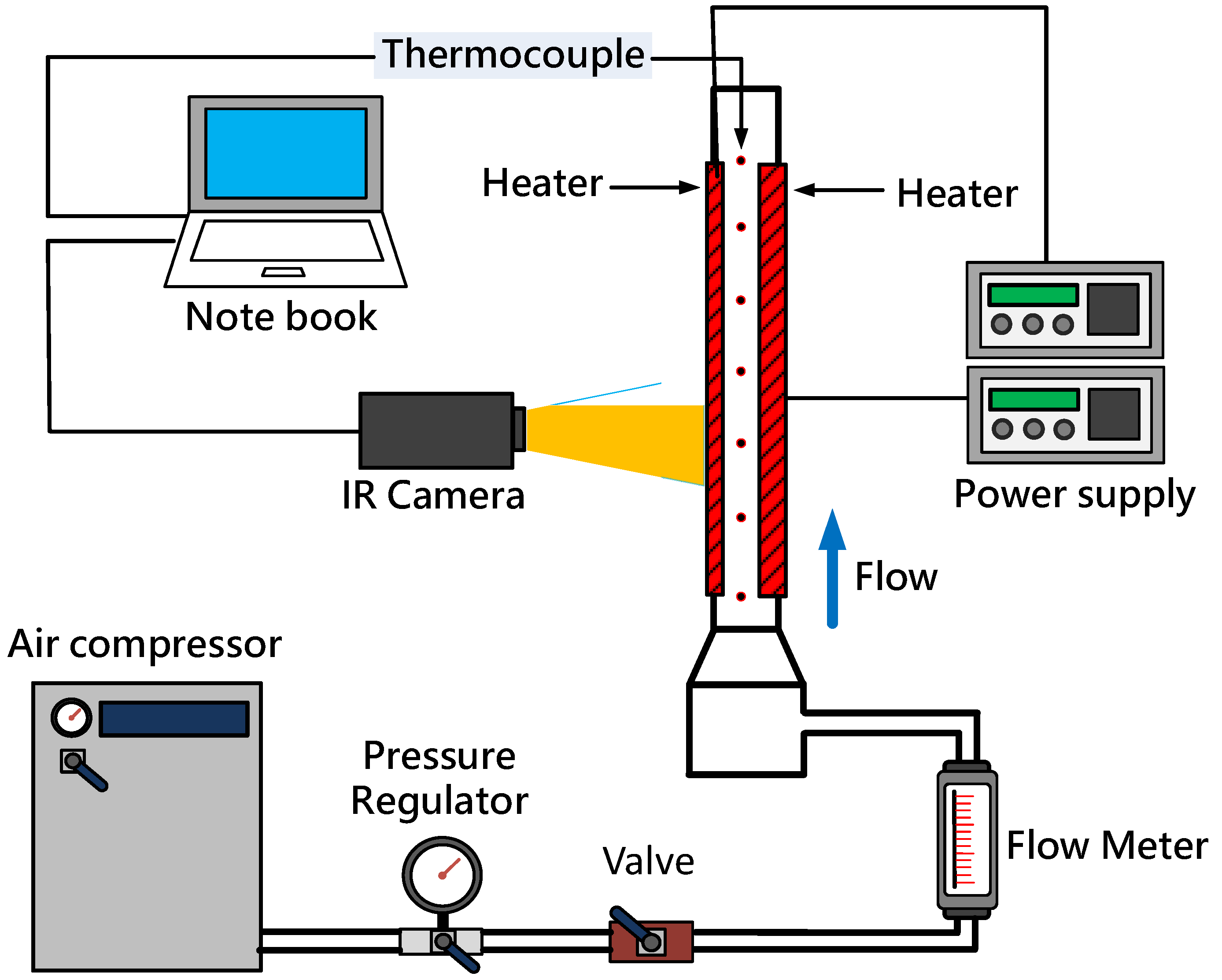
A schematic of the flow facility and test section is shown in Figure 1. The air flow rate from an air compressor was measured using a rotameter (Fong-Jei, Taipei, Taiwan, F-type) installed upstream of the test section. A pressure regulator maintained the air pressure at desirable level, and a valve controlled the flow rate. Meanwhile, the flow was directed into a plenum chamber located upstream of the test section. The air temperature was 25 °C, and the volume flow rate ranged from 200 to 600 L/min. The channel wall was heated using resistance heaters, and an infrared camera (FLIR A325sc, Oregon, USA) detected the wall temperature. The pressure drop of the ribbed channel was recorded using a differential pressure gauge (Willes, WDMP 3000, 0–40 kPa, Anguilla, BWI). A translational stage was used for precise positioning of the infrared camera so that the regions of interest for heat transfer measurement could be obtained. Thermocouples were installed into the channel at equally spaced points to record the air temperatures, and the data were recorded by a thermocouple module (NI 9213, Texas, USA).
The drawing of the trapezoidal cooling channel manufactured from polyvinyl chloride (PVC) is shown in Figure 2, which has been used in our previous publication [20]. It comprised an unheated entrance (105 mm), heated region (690 mm), and outlet section (103 mm). A contraction part (100 mm length) connected the inlet plenum and the trapezoidal test section. The vertical and inclined walls were heated during the experiment, and the areas were 690 × 20 and 690 × 25 mm2, respectively. In the current configuration, each pixel size in the infrared image was estimated to be 0.2 × 0.2 mm2. The heating was controlled using a polyimide film heater (0.15 mm thick). The heater surface for infrared measurement was coated with black paint for uniform emissivity. To obtain the emissivity of the surface, a copper block was also coated with the black paint and prepared for heating to the predetermined temperatures. A thermocouple was installed in the copper block to detect the temperature. Therefore, the emissivity on the surface can be obtained using the temperature measurement from thermocouple and infrared camera. The emissivity on the surface was 0.94 [21]. To prevent heater deformation, a stainless steel sheet (0.3 mm thickness) was attached to the heater surface using a thermal tape (0.15 mm). These two heater elements were tightly fastened to the outer frame of the test section. More information can be found in our previously published paper [20].
Figure 3 plots the four rib geometries (V-shaped, full X-shaped, and upstream and downstream cutback X-shaped). These acrylic ribs were placed on the inclined wall and vertical wall in the right trapezoidal channel, exhibiting an angle of 53° at the longer base, and this rib dimension is the same as that in our previous publication [20]. These ribs had an angle of attack of 45° with respect to the mainstream flow. The square ribs had a cross-section of 2 × 2 mm, giving a rib height-to-hydraulic diameter ratio of 0.128. It should be noted that the ribs on the inclined wall were longer, and the ribs cannot be extended to the corner of the shorter base. Since the wall temperature was taken from outer side of the channel, the heat transfer results were presented on the smooth endwalls between ribs and the regions underneath the ribs were excluded.
The ribs were placed in a staggered arrangement on the inclined wall and vertical wall as demonstrated in Figure 4. It should be noted that the ribs were placed from the entrance of the channel, and the measurements were taken from x/Dh = 16.5 to 30.6 in the streamwise direction. Because the measurement regions were slender, the measurements were taken at four subsections as marked by the dashed lines to obtain higher-resolution infrared images. The distances between the ribs were 20 mm and 40 mm, giving a rib spacing-to-height ratio of 10 and 20, respectively. For the smaller rib spacing (P/e = 10), there were 32 and 33 ribs on the vertical wall and inclined wall, respectively. For all X-shaped ribs, only larger rib spacing (P/e = 20) was performed to avoid the rib interference issue.
The heat transfer coefficient on the rib-roughened surface can be calculated as:
The heat input (0.36–1.2 W/cm2) was calculated from power output of the film heater. The wall temperature was recorded using the infrared camera, and the fluid bulk temperature was measured using thermocouples. Since the infrared camera can only capture the outer surface temperature, the real inner wall temperature was determined using a thermal resistance model [21]. The temperature difference between the inner and outer wall was within 1.5 °C. It should be noted that the heat transfer coefficient was calculated for each pixel in the infrared images. The heat loss from conduction and radiation was subtracted from the heat input so as to identify the net heat rate for heat convection. The heat loss experiment was conducted without the air flow at several different wall temperatures, and meanwhile, the insulation material was inserted into the channel to eliminate natural convection. During the heating process, the heat input was equivalent to the heat loss from the test channel to the ambient. Accordingly, the heat loss could be linearly interpolated using the difference between the wall and ambient temperatures [20]. The Nusselt number can be calculated as:
This equation was calculated using the hydraulic diameter of the smooth channel (15.6 mm). The air Prandtl number is 0.7, and the Nusselt number ratio was calculated using the Gnielinski correlation [22]:
where the friction factor was calculated using the literature correlation [22]:
The friction factor (f) was calculated according to the pressure drop across the ribbed channel and normalized using the correlation (fo):
The uncertainty analysis was performed using the method proposed by Kline and McClintock [23]. For heat transfer measurement, the primary sources of uncertainties in the experiment were the mainstream temperature, wall temperature, heat input, heat loss, and fluid properties. The uncertainty for the Nusselt number was calculated as follows:
The maximal uncertainty in the Nusselt number was 6% at the Reynolds number of 10,000. For the flow Reynolds number, the uncertainty was primarily from the flow meter and the uncertainty was calculated as follows:
The estimated maximal uncertainty in the Reynolds number was 4.4%. The uncertainty of the friction factor was also estimated, and the uncertainties in these test parameters are summarized in Table 1.
3. Results
3.1. Heat Transfer
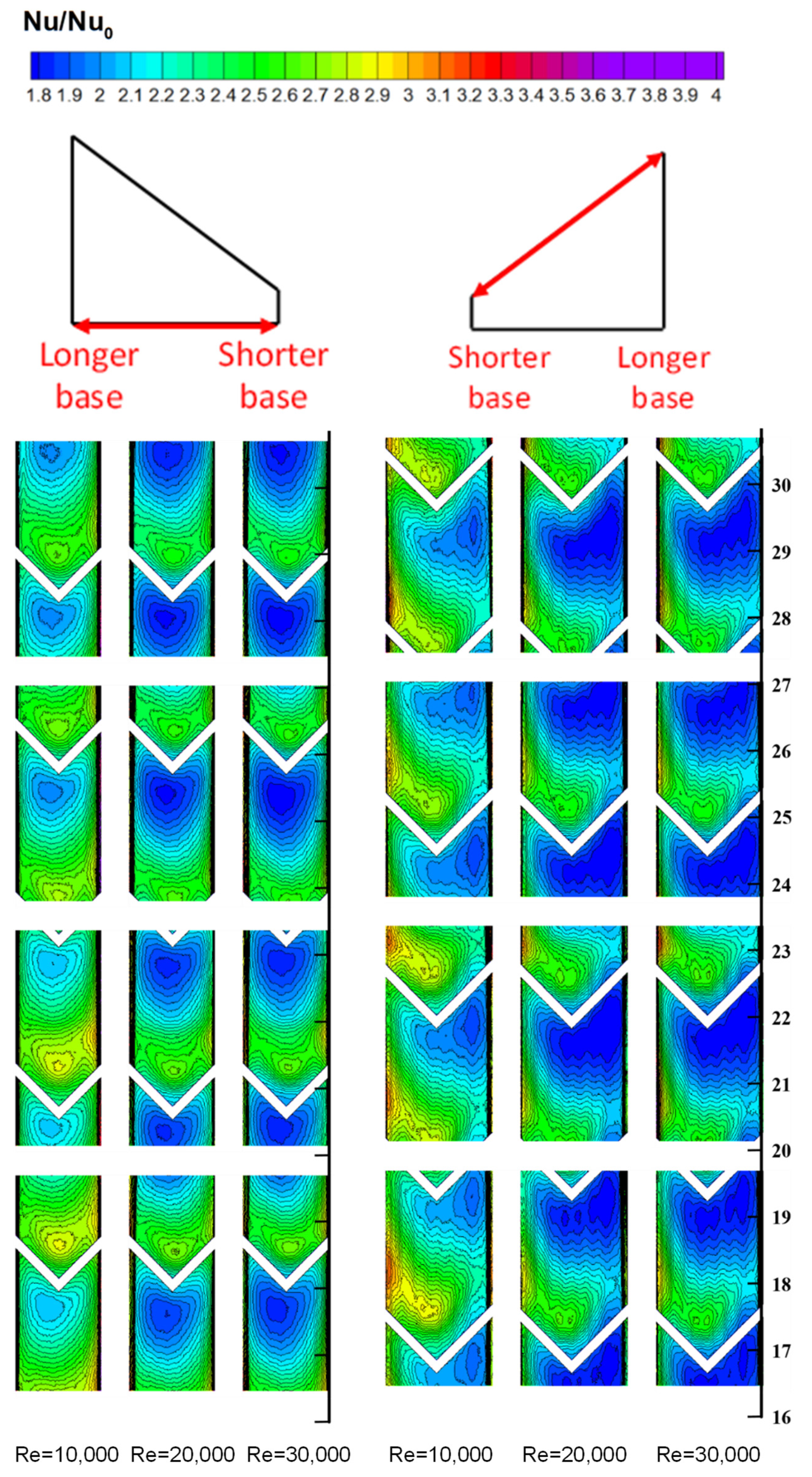
In this trapezoidal channel, influences of ribs on heat transfer distribution were reported on the vertical and inclined walls. Nusselt number ratios for the V-shaped ribs with two rib spacings (P/e = 10 and 20) were selected as a baseline case. For the closer spacing (P/e = 10), the heat transfer enhancement caused by the flow reattachment from ribs can be clearly observed in Figure 5. There is no appreciable difference in the Nusselt number distribution within these four subsections, demonstrating that the number of ribs were sufficient for the Nusselt number to reach a periodically fully developed value. Due to the trapezoidal channel, the heat transfer distribution was asymmetric, and high heat transfer regions was observed near the shorter base. This was primarily caused by the flow accelerating through the shorter base since this region was not fully covered by ribs. Overall, the heat transfer distribution on the vertical was more symmetric than that on the inclined wall. On the inclined wall, the sharper corner (53°) near the longer base was not beneficial for heat transfer improvement. A similar finding was also presented for a triangular channel with fully and partial ribbed walls, heat transfer enhancement near the sharper corner was also quite low [24].
Figure 6 shows the Nusselt number ratios for the larger rib spacing (P/e = 20). Although heat transfer enhancement by the ribs were still observed, the larger spacing led to lower heat transfer regions downstream of the reattachment zone, and the heat transfer started to degrade as the flow started to develop. This wider rib spacing generated a thicker boundary layer after flow reattachment as indicated in literature [25], leading to smaller heat transfer enhancement than that of the smaller spacing case.
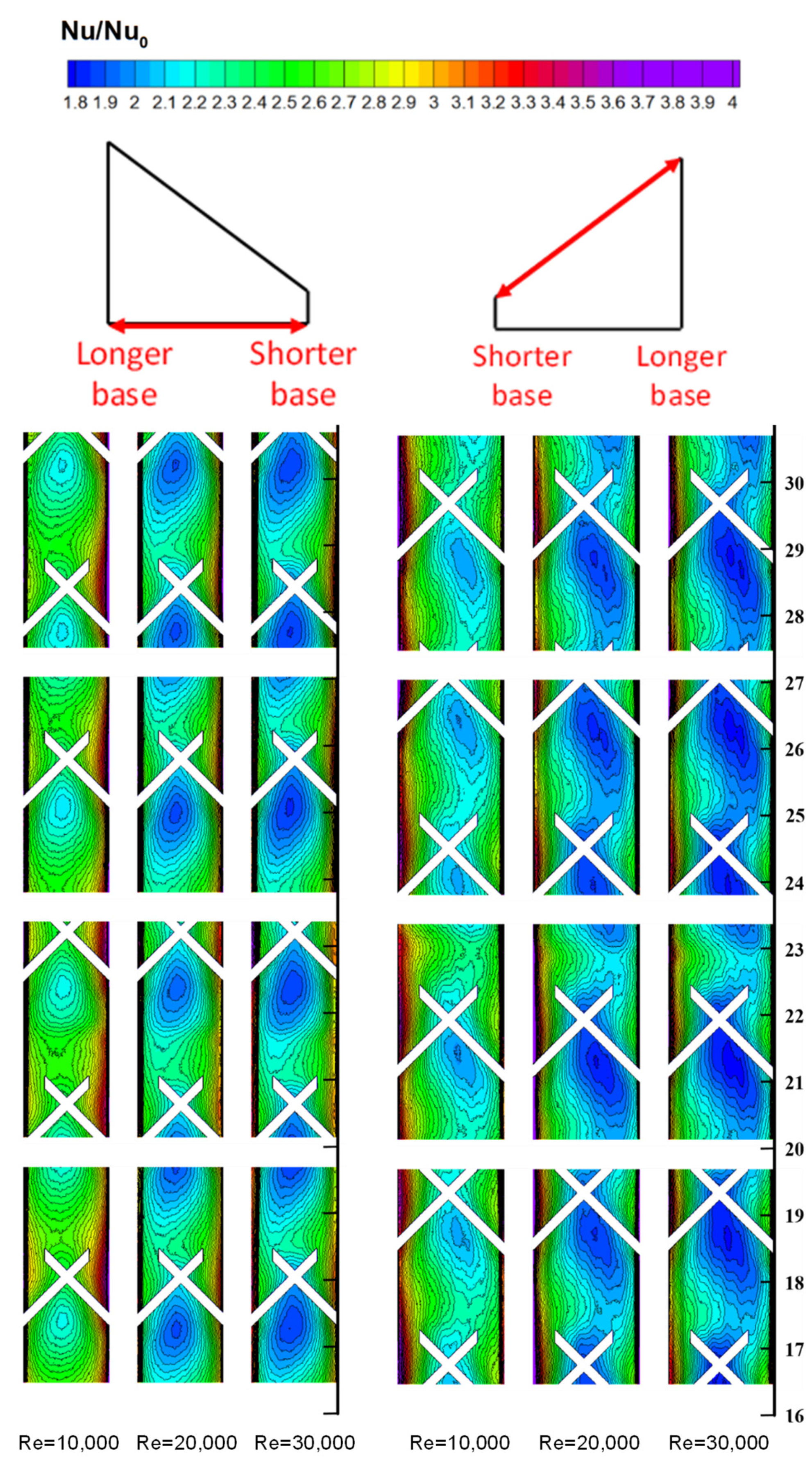
To improve the performance of the V-shaped ribs, the X-shaped ribs were proposed, and the Nusselt number ratios are shown in Figure 7. According to our previous study, the single X-shaped rib caused additional flow vortices and more secondary flow cells [20]. Near the side wall, the secondary flow demonstrated flow accelerating and contributed to higher heat transfer enhancement. A larger rib spacing of 20 was selected to avoid the rib interference issue. Despite the large rib spacing, the elongated rib structure demonstrated superior heat transfer enhancement, particularly on the vertical wall. This was primarily caused by the high heat transfer zones from the flow reattachment near the corner. Compared to the V-shaped ribs with the same rib spacing, the low heat transfer regions were significantly reduced, which indicated that the X-shaped ribs were effective for disturbing the boundary layer flow.
The X-shaped ribs produced greater heat transfer enhancement, while the pressure loss could be substantial because of the increased rib-roughened area. Therefore, the cutback ribs were introduced. The geometry of the cutback ribs can be interpreted as a combination of large and small V-shaped ribs. For the upstream cutback X-shaped ribs (Figure 8), the additional upstream rib segment produced flow acceleration and promoted heat transfer enhancement, which demonstrated higher Nusselt number ratios compared with the V-shaped ribs. However, the heat transfer enhancement was lower than that of the full X-shaped ribs because the cutback structure generated weaker secondary flow cells. The high heat transfer enhancement caused by the secondary flow generated by ribs was still noticeable downstream of the ribs and near the shorter base of the channel.
For the downstream cutback ribs (Figure 9), the secondary flow generated by the upstream V-shaped structure was hindered by the downstream cutback element, and the higher heat transfer regions were observed near the longer and shorter bases. Consequently, the heat transfer near the centerline was smaller for both the inclined and vertical walls. Although downstream cutback design demonstrated higher heat transfer for the single rib case [20], the secondary flows generated by the repeated ribs were less effective for heat transfer enhancement. For both cutback rib cases, the heat transfer on the inclined wall near the sharper corner was still low.
The average Nusselt number ratios on the inclined and vertical wall were plotted in Figure 10. These Nu ratios were the average values from every point on the measurement plane, and the Nusselt number ratios on the vertical wall were slightly higher than those on the inclined wall. Despite the larger rib spacing (P/e = 20) of the full X-shaped rib, it showed superior heat transfer enhancement on both the inclined and vertical walls. The Nusselt number ratios from the full X-shaped ribs were 15–25% higher than those from the V-shaped ribs with the same rib spacing (P/e = 20). The full X-shaped rib and V-shaped rib with smaller spacing (P/e = 10) showed the highest Nusselt number ratios among all the cases. The upstream cutback ribs were better than the downstream cutback ribs, which was different from the single rib case [20]. This was primarily caused by the repeated staggered ribs, which generated lower heat transfer enhancement regions upstream of the ribs. The V-shaped ribs with larger spacing showed the lowest Nusselt number ratios, approximately 2.1–2.5.
3.2. Friction Factor and Thermal Performance
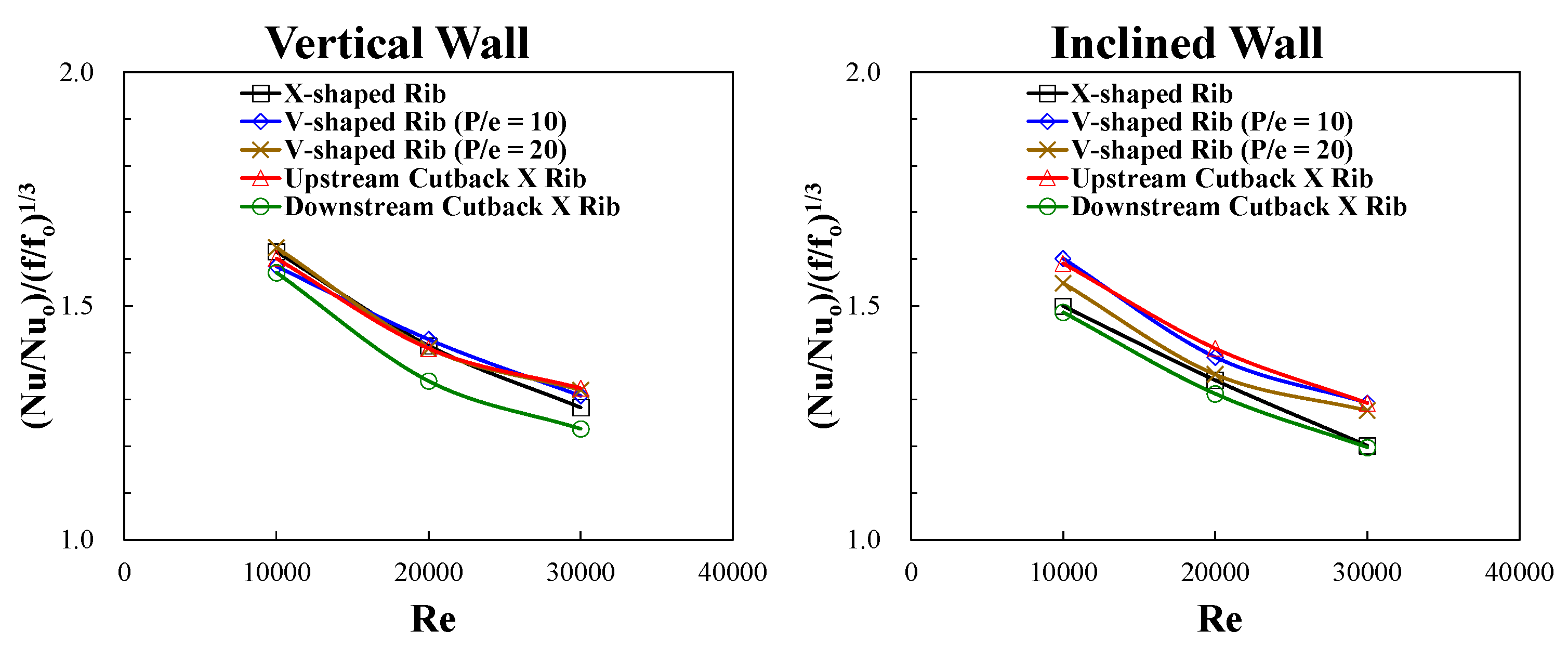
The friction factor is shown in Figure 11, and the X-shaped ribs show the highest friction factor. It should be noted that X-shaped rib even has higher friction factor than that of the V-shaped ribs having smaller rib spacing (P/e = 10). The cutback X-shaped ribs were effective for reducing the pressure drop across the channel, and the friction factor was 25–30% lower compared with the full X-shaped ribs. The V-shaped ribs with wider spacing demonstrated the lowest friction factor. With the measured heat transfer and friction factor results, the thermal performance was computed for each rib configuration, as shown in Figure 12. Although the full X-shaped ribs exhibited the highest heat transfer, the thermal performance was hindered by the noticeable pressure loss. In addition, the downstream cutback X rib was successful for the single rib case [20], but the repeated rib configuration led to the lowest thermal performance. For the upstream cutback rib, the smaller friction factor was favorable for enhancing thermal performance. The V-shaped ribs (P/e = 10) and upstream cutback X ribs showed the highest thermal performance.
4. Conclusions
Heat transfer and friction factor of various X-shaped ribs were experimentally measured in a trapezoidal cooling channel. V-shaped, X-shape, and upstream and downstream cutback X-shaped ribs were studied. The conclusion can be summarized as follows:
- The X-shaped ribs produced the highest heat transfer despite the large rib spacing. The expanded rib structure contributed to intensive flow mixing and expanded the heat transfer enhancement regions around the ribs. However, this was also accompanied by the largest pressure drop.
- The cutback X-shaped ribs can effectively reduce the pressure loss caused by the full X-shaped ribs. Consequently, the V-shaped ribs (P/e = 10) and upstream cutback X ribs showed the highest thermal performance.
- The Nusselt number ratios were higher in the vicinity of the shorter base in the trapezoidal channel regardless of the rib configuration. It should be noted that the rib spacing and height ratios may not be optimal, and detailed parametric study could potentially increase the rib performance.
Author Contributions
Conceptualization, W.-J.S. and Y.-H.L.; data curation, W.-J.S.; funding acquisition, Y.-H.L.; investigation, W.-J.S. and Y.-H.L.; methodology, W.-J.S. and Y.-H.L.; project administration, Y.-H.L.; supervision, Y.-H.L.; validation, W.-J.S. and Y.-H.L.; writing—original draft, Y.-H.L.; writing—review and editing, Y.-H.L. All authors have read and agreed to the published version of the manuscript.
Funding
This research was funded by the Ministry of Science and Technology in Taiwan under the grant number MOST 107-2221-E-009-068-MY3.
Conflicts of Interest
The authors declare no conflict of interest.
Nomenclature
| A | Heat transfer area |
| Dh | Hydraulic diameter of the trapezoidal channel |
| e | Rib height |
| f | Friction factor |
| fo | Friction factor in the smooth tube with fully developed flow |
| h | Convective heat transfer coefficient |
| k | Thermal conductivity of air |
| L | Length of the rib-roughened region |
| Nu | Nusselt number |
| Nuo | Nusselt number calculated using Gnielinski correlation |
| P | Rib spacing |
| Pr | Prandtl number of air |
| ΔP | Pressure drop across the ribbed region |
| Qin | Heat input |
| Qloss | Heat loss |
| Re | Reynolds number () |
| Tw | Surface temperature |
| Tb | Bulk temperature |
| V | Flow velocity |
| x | Streamwise distance |
| y | Spanwise distance |
| ρ | Density of air |
| μ | Dynamic viscosity of air |
References
- Han, J.C.; Dutta, S.; Ekkad, S. Gas Turbine Heat Transfer and Cooling Technology, 2nd ed.; CRC Press: New York, NY, USA, 2012; pp. 363–441. [Google Scholar]
- Han, J.C.; Park, J.S.; Lei, C.K. Heat transfer enhancement in channels with turbulence promoters. J. Eng. Gas Turbines Power 1985, 107, 628–635. [Google Scholar] [CrossRef]
- Han, J.C.; Park, J.S. Developing heat transfer in rectangular channels with rib turbulators. Int. J. Heat Mass Transf. 1988, 31, 183–195. [Google Scholar] [CrossRef]
- Han, J.C.; Ou, S.; Park, J.S.; Lei, C.K. Augmented heat transfer in rectangular channels of narrow aspect ratios with rib turbulators. Int. J. Heat Mass Transf. 1989, 32, 1619–1630. [Google Scholar] [CrossRef]
- Liou, T.M.; Hwang, J.J.; Chen, S.H. Simulation and measurement of enhanced turbulent heat transfer in a channel with periodic ribs on one principal wall. Int. J. Heat Mass Transf. 1993, 36, 507–517. [Google Scholar] [CrossRef]
- Lau, S.C.; Kukreja, R.T.; McMillin, R.D. Effects of V-shaped rib arrays on turbulent heat transfer and friction of fully developed flow in a square channel. Int. J. Heat Mass Transf. 1991, 34, 1605–1616. [Google Scholar] [CrossRef]
- Han, J.C.; Zhang, Y.M. High performance heat transfer ducts with parallel broken and V-shaped broken ribs. Int. J. Heat Mass Transf. 1992, 35, 513–523. [Google Scholar] [CrossRef]
- Kukreja, R.T.; Lau, S.C.; McMillin, R.D. Local heat/mass transfer distribution in a square channel with full and V-shaped ribs. Int. J. Heat Mass Transf. 1993, 36, 2013–2020. [Google Scholar] [CrossRef]
- Wang, L.; Sunden, B. An experimental investigation of heat transfer and fluid flow in a rectangular duct with broken V-shaped ribs. Exp. Heat Transf. 2004, 17, 243–259. [Google Scholar] [CrossRef]
- Tanda, G. Heat transfer in rectangular channels with transverse and V-shaped broken ribs. Int. J. Heat Mass Transf. 2004, 47, 229–243. [Google Scholar] [CrossRef]
- Lee, D.H.; Rhee, D.H.; Kim, K.M.; Cho, H.H.; Moon, H.K. Detailed measurement of heat/mass transfer with continuous and multiple V-shaped Ribs in rectangular channel. Energy 2009, 34, 1770–1778. [Google Scholar] [CrossRef]
- SriHarsha, V.; Prabhu, S.V.; Vedula, R.P. Influence of rib height on the local heat transfer distribution and pressure drop in a square channel with 90 continuous and 60 V-broken ribs. Appl. Therm. Eng. 2009, 29, 2444–2459. [Google Scholar] [CrossRef]
- Liu, Y.H.; Lai, S.Y. Heat transfer augmentation in rotating triangular channels with discrete and V-shaped ribs. J. Thermophys. Heat Transf. 2012, 26, 603–611. [Google Scholar] [CrossRef]
- Liu, Y.H.; Lo, Y.H.; Li, X.X.; Huh, M. Heat transfer and friction in a square channel with ribs and grooves. J. Thermophys. Heat Transf. 2016, 30, 144–151. [Google Scholar] [CrossRef]
- Huang, K.T.; Liu, Y.H. Enhancement of mist flow cooling by using V-shaped broken ribs. Energies 2019, 12, 3785. [Google Scholar] [CrossRef] [Green Version]
- Wright, L.M.; Fu, W.L.; Han, J.C. Thermal performance of angled, V-shaped, and W-shaped rib turbulators in rotating rectangular cooling channels (AR = 4:1). J. Turbomach. 2004, 126, 604–614. [Google Scholar] [CrossRef]
- Maurer, M.; von Wolfersdorf, J.; Gritsch, M. An experimental and numerical study of heat transfer and pressure losses of V-and W-shaped ribs at high Reynolds numbers. In Proceedings of the ASME Turbo Expo, American Society of Mechanical Engineers, Montreal, QC, Canada, 14–17 May 2007. [Google Scholar]
- Lamont, J.A.; Ekkad, S.V.; Anne Alvin, M. Effect of rotation on detailed heat transfer distribution for various rib geometries in developing channel flow. J. Heat Transf. 2014, 136, 011901. [Google Scholar] [CrossRef]
- Ravi, B.V.; Singh, P.; Ekkad, S.V. Numerical investigation of turbulent flow and heat transfer in two-pass channels. Int. J. Therm. Sci. 2017, 112, 31–43. [Google Scholar] [CrossRef]
- Su, W.J.; Huang, T.H.; Liu, Y.H. Heat transfer and friction in trapezoidal channels with X-shaped ribs. Int. J. Therm. Sci. 2021, 164, 106871. [Google Scholar] [CrossRef]
- Wang, S.K.; Liu, Y.H. Heat transfer and friction measurement in pin-fin arrays under mist flow condition. J. Therm. Sci. Eng. Appl. 2019, 11, 021012. [Google Scholar] [CrossRef]
- Incropera, F.P.; Dewitt, D.P.; Bergman, T.L.; Lavine, A.S. Principles of Heat and Mass Transfer, 8th ed.; John Wiley & Sons: Singapore, 2017; pp. 480–503. [Google Scholar]
- Kline, S.J.; McClintock, F.A. Describing uncertainty in single-sample experiments. Mech. Eng. 1953, 75, 3–8. [Google Scholar]
- Zhang, Y.M.; Gu, W.Z.; Han, J.C. Augmented heat transfer in triangular ducts with full and partial ribbed walls. J. Thermophys. Heat Transf. 1994, 8, 574–579. [Google Scholar] [CrossRef]
- Han, J.C. Heat transfer and friction characteristics in rectangular channels with rib turbulators. J. Heat Transf. 1988, 110, 321–328. [Google Scholar] [CrossRef]
Figure 1.
Experimental setup for heat transfer measurement.

Figure 2.
Drawing of the test section.

Figure 3.
Drawing of the test section.

Figure 4.
Rib configuration and measurement region in the flow channel.

Figure 5.
Nusselt number ratios for the V-shaped rib (P/e = 10).

Figure 6.
Nusselt number ratios for the V-shaped rib (P/e = 20).

Figure 7.
Nusselt number ratios for the X-shaped rib (P/e = 20).

Figure 8.
Nusselt number ratios for the upstream cutback X-shaped rib (P/e = 20).

Figure 9.
Nusselt number ratios for the downstream cutback X-shaped rib (P/e = 20).

Figure 10.
Average Nusselt number ratios on the vertical wall and inclined wall.

Figure 11.
Friction factor ratios.

Figure 12.
Thermal performance.


Table 1.
Uncertainties in the test parameters.
| Parameter | Uncertainty |
| Voltage | 0.01 V |
| Resistance | 1 Ω |
| Fluid temperature (Thermocouple) | 0.5 °C |
| Surface temperature (Infrared) | 0.6 °C |
| Heat input | 1.6% |
| Heat transfer coefficient | 5.8% |
| Flow rate | 4% |
| Pressure drop (Pressure transducer) | 1% |
| Friction factor | 8.2% |
Publisher’s Note: MDPI stays neutral with regard to jurisdictional claims in published maps and institutional affiliations. |
© 2021 by the authors. Licensee MDPI, Basel, Switzerland. This article is an open access article distributed under the terms and conditions of the Creative Commons Attribution (CC BY) license (https://creativecommons.org/licenses/by/4.0/).
Share and Cite
MDPI and ACS Style
Su, W.-J.; Liu, Y.-H. Thermal Performance of V-Shaped and X-Shaped Ribs in Trapezoidal Cooling Channels. Energies 2021, 14, 4826. https://0-doi-org.brum.beds.ac.uk/10.3390/en14164826
AMA Style
Su W-J, Liu Y-H. Thermal Performance of V-Shaped and X-Shaped Ribs in Trapezoidal Cooling Channels. Energies. 2021; 14(16):4826. https://0-doi-org.brum.beds.ac.uk/10.3390/en14164826
Chicago/Turabian StyleSu, Wei-Jie, and Yao-Hsien Liu. 2021. "Thermal Performance of V-Shaped and X-Shaped Ribs in Trapezoidal Cooling Channels" Energies 14, no. 16: 4826. https://0-doi-org.brum.beds.ac.uk/10.3390/en14164826
Note that from the first issue of 2016, this journal uses article numbers instead of page numbers. See further details here.