Article

Water Cycle Algorithm Optimized Type II Fuzzy Controller for Load Frequency Control of a Multi-Area, Multi-Fuel System with Communication Time Delays

1
Department of Electrical Engineering, Vasireddy Venkatadri Institute of Technology, Guntur 522508, India
2
Department of Electrical Engineering, Anurag College of Engineering Ghatkesar, Telangana 501301, India
3
Department of Electrical Engineering, Malla Reddy Engineering College (A) Maisammaguda, Telangana 500100, India
4
Electrical Power and Machines Department, Faculty of Engineering, Zagazig University, Zagazig 44519, Egypt
5
ISTHY, Institut International sur le Stockage de l’Hydrogène, 90400 Meroux-Moval, France
6
Department of Electrical and Electronics Engineering, National Institute of Technology Delhi, New Delhi 110040, India
7
College of Engineering at Wadi Addawaser, Prince Sattam Bin Abdulaziz University, Wadi Addawaser 11991, Saudi Arabia
8
Electrical Engineering Department, Faculty of Engineering, Aswan University, Aswan 81542, Egypt
*
Author to whom correspondence should be addressed.
Submission received: 6 July 2021 / Revised: 9 August 2021 / Accepted: 18 August 2021 / Published: 30 August 2021

Abstract

:
This paper puts forward the implementation of an intelligent type II fuzzy PID (T2-FPID) controller tweaked with a water cycle algorithm (WCA), subjected to an error multiplied with time area over integral (ITAE) objective index for regularizing the variations in frequency and interline power flow of an interconnected power system during load disturbances. The WCA-based T2-FPID is tested on a multi-area (MA) system comprising thermal-hydro-nuclear (THN) (MATHN) plants in each area. The dynamical behavior of the system is analyzed upon penetrating area 1 with a step load perturbation (SLP) of 10%. However, power system practicality constraints, such as generation rate constraints (GRCs) and time delays in communication (CTDs), are examined. Afterward, a territorial control scheme of a superconducting magnetic energy storage system (SMES) and a unified power flow controller (UPFC) is installed to further enhance the system performance. The dominancy of the presented WCA-tuned T2-FPID is revealed by testing it on a widely used dual-area hydro-thermal (DAHT) power system model named test system 1 in this paper. Analysis reveals the efficacy of the presented controller with other approaches reported in the recent literature. Finally, secondary and territorial regulation schemes are subjected to sensitivity analysis to deliberate the robustness.

1. Introduction

In the present scenario, rapid industrialization demands more electrical energy consumption. Participation of electrical utilities in the existing power system has been rapidly increasing to meet this ever-changing power demand. With the penetration of these electrical utilities, an interconnected system becomes more complex. The electric utilities are sub-grouped as control areas, which connect the remaining areas via transmission lines named tie lines. As soon as a small load disturbance occurs on any of the control areas, there exists a considerable disturbance in the area frequency, making the entire interconnected system unhealthy. However, the stability and efficacy of the power system are more likely to be relied on damping out the variations in line flow and frequency that arise under disturbance conditions at the earliest. This task can be effectively addressed by a load frequency controller (LFC). An LFC can accomplish the mechanism of balancing the power through a secondary regulator by altering the set point valve of the generation unit, thereby regulating the system frequency. Thus, a supreme and robust secondary regulatory control technique is essential to neutralize the impact of load variations on system performance.
Tungadio et al. [1] reported various power system models that have been deliberated by researchers in LFC study. Elgerd et al. [2] initiated the visualization of isolated thermal plant behavior under load disturbances. Since then, more researchers are enlightened to contribute governing techniques in the LFC domain. Nanda et al. [3] investigated two-area and three-area thermal systems with unequal generation capacity. Researchers in [4] carried out the analysis of the performance assessment of a DAHT system on load disturbances. Ravi et al. [5] investigated the traditional dual-area system incorporated with traditional generating sources of thermal-hydro-gas units in each area. Authors in [6] analyzed DAHT system behavior without and with a generation limiter of a GRC in order to demonstrate its impact on system performance. Later, researchers concentrated on considering the integration of renewable plants with existing conventional units for the study of LFCs. Irrespective of the test system models, researchers are more concentrated on designing and optimizing secondary regulators (SRs) to improve power system performance [7].
Several conventional PI/PID/PIDN/PIDD [8,9], modified PID [10], higher-order degree-of-freedom (DOF) 2DOFPID/3DOFPID [11], intelligent fuzzy (F) PID (FPID) [12], fractional-order (FO) FOPI/FOPID [13], and other FO and fuzzy-based cascade controllers [14] are reported in the literature. Implementation of intelligent fuzzy controllers in the LFC domain are gaining momentum year by year; in this regard, type II fuzzy controllers are preferred over type I for various engineering optimization problems, and the strength of type II fuzzy controllers is extensively discussed in [15]. However, the selection of an appropriate soft computing algorithm to fine-tune the parameters of SRs is a most challenging task. Different soft computing approaches that have been extensively implemented by researchers in the domain of LFC study are particle swarm optimization (PSO) [16], grasshopper optimization algorithm (GOA) [10], pattern search (PS) [17], sine-cosine algorithm (SCA) [13], lightning search algorithm (LSA), bacterial foraging optimizer (BFO) [3], genetic algorithm (GA) [4], firefly algorithm (FA) [12], gravitational search algorithm (GSA) [17], differential evolution (DE) [18], imperialist competitive algorithm (ICA) [14], symbiotic organism search (SOS) [15], whale optimizer (WO) [19], artificial field algorithm (AEFA) [20], gray wolf optimizer (GWO) [21], and some hybrid (h) approaches such as hFA-PS [8], hPSO-PS [22], combined DE-AEFA [7], HAEFA [16], and an FA-PSO-GSA combination technique [23]. However, every year, various optimization approaches have been proposed by researchers based on migration, hierarchal, and hunting mechanisms of various organisms in nature.
Though the aforementioned optimizations are widely used by researchers, most of them get trapped into local minima and are unable to use proper search space [19]. This opens the space and scope for the use of novel meta-heuristic searching methods in the study of LFCs. So, in this paper, an effective approach of WCA is used to optimize T2-FPID regulator parameters to maintain the stability of interconnected systems. Though this WCA is used in LFC study, the combination of the WCA approach and the T2-FPID controller has not been studied so far and no literature is reported. This inspires the authors to implement this control mechanism along with territorial strategies of FACTS and energy storage devices (ESDs) for further enhancement. A complex interconnected system definitely needs an additional regulatory mechanism as SRs are unable to regulate the system deviations under sudden large disturbances. An additional strategy of a UPFC and an SMES is implemented in this work because of their significant features.
In view of the above, the contributions of this paper are:
(a)
The performance of the WCA-optimized T2-FPID controller is assessed for LFC study.
(b)
The efficacy of the proposed WCA-tuned T2-FPID controller is revealed with other control approaches reported in the literature by implementing test system 1.
(c)
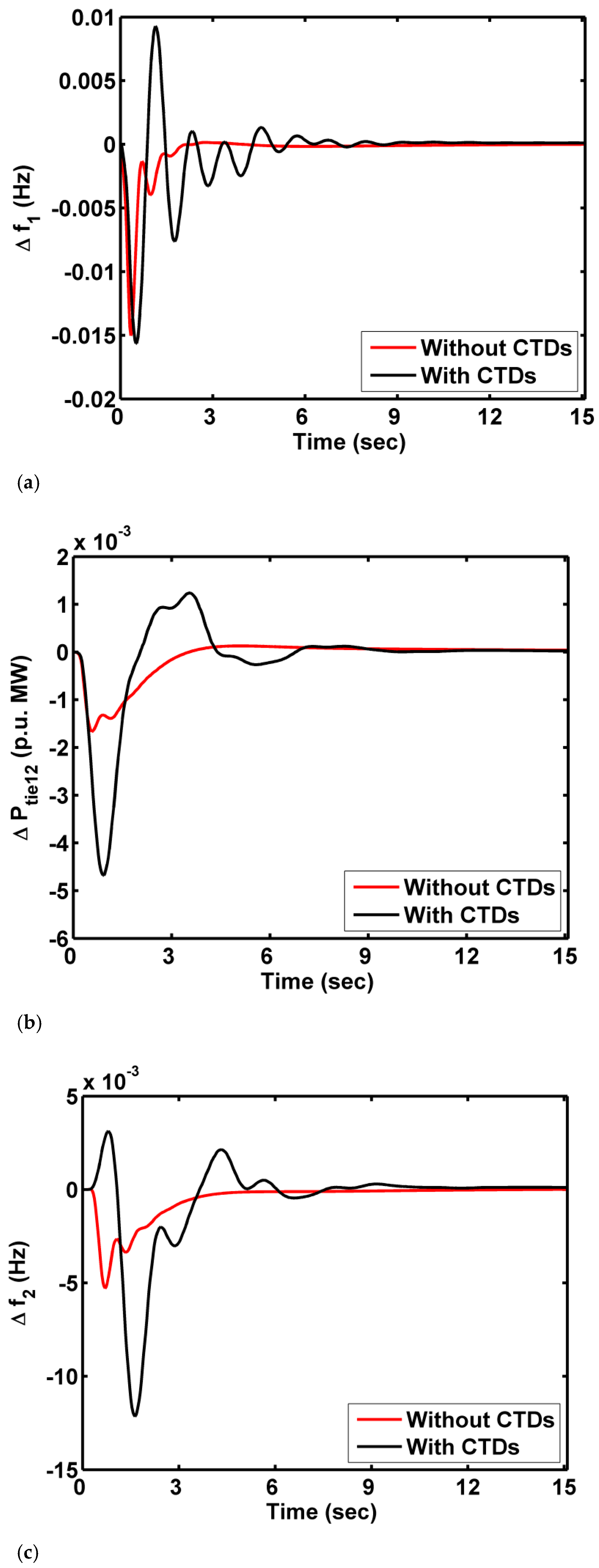
Impact of CTDs on the MATHN system is revealed and the importance of considering CTDs is discussed extensively.
(d)
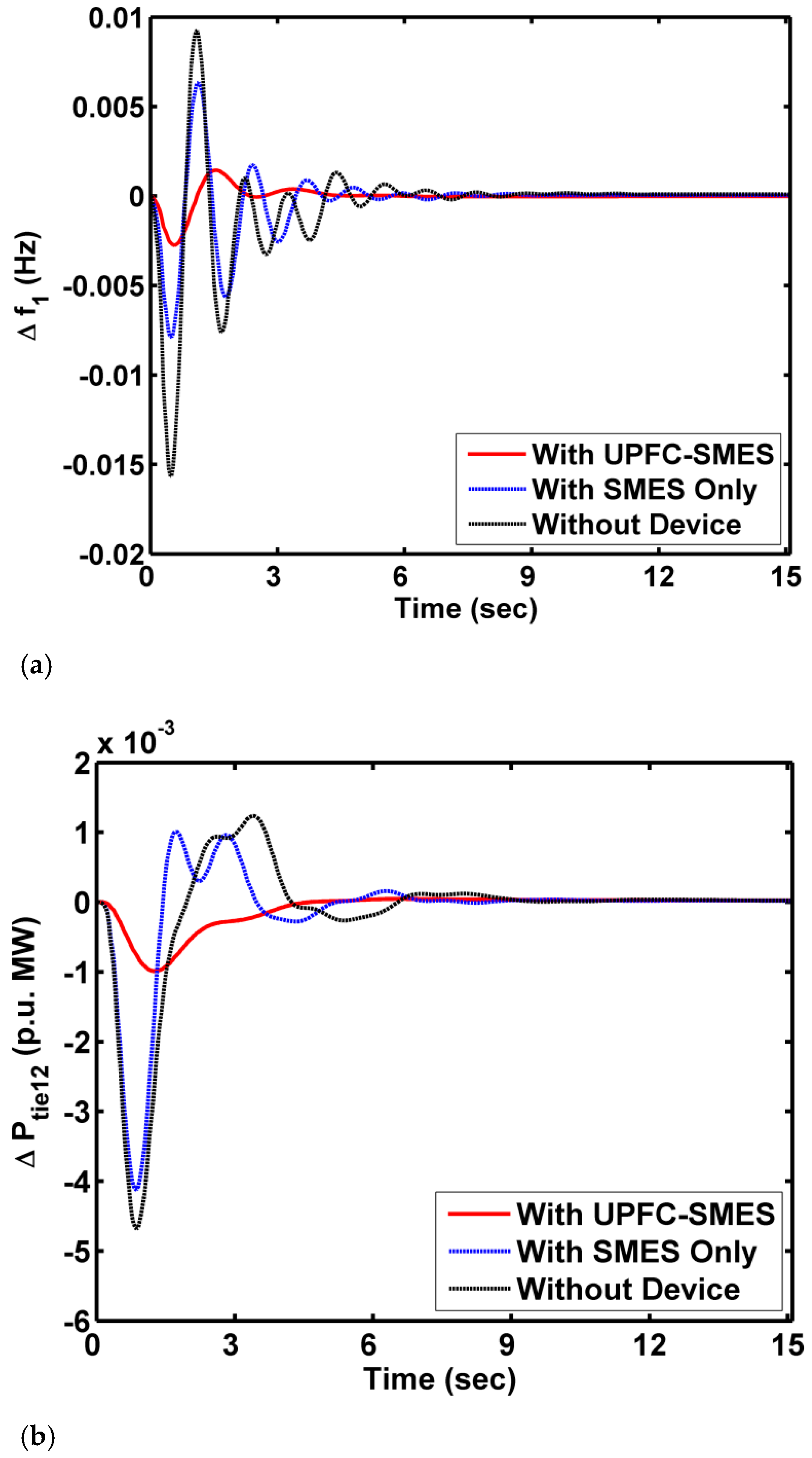
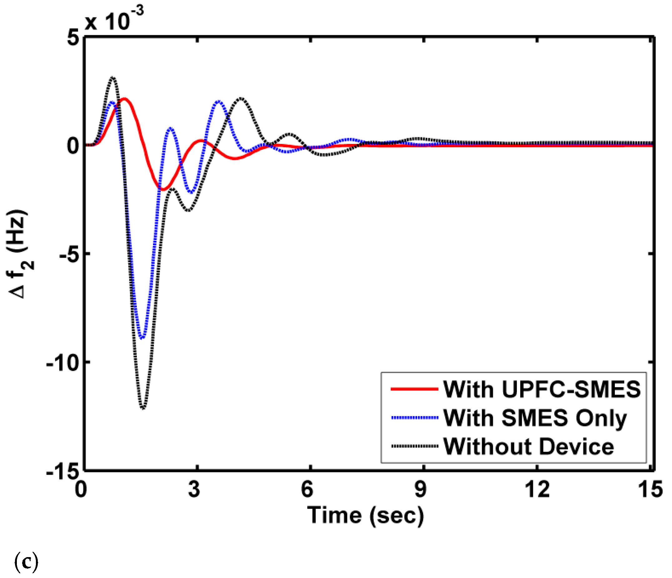
A UPFC-SMES additional strategy is implemented to further improve system performance.
(e)
Sensitivity analysis is performed to showcase the presented coordinated regulation robustness.

2. Materials and Methods

Two power system models are used in this work to implement the presented T2-FPID controller based on the WCA approach. A DAHT model named test system 1 with unique generation capacities is analyzed by laying area 1 with an SLP of 10%. Another model is a dual-area THN system referred to as test system 2 in this paper. The constraints of practicality, such as GRCs and CTDs, are considered for test system 2 to exercise the research close to the nature of realistic practice. The test system models 1 and 2 are depicted in Figure 1 [4] and Figure 2 [21], respectively. The capacity of the DAHT model is 2000 MW, with areas of unique generation capacities, and the MATHN system has a 2000 MW power generation capacity for each area. Investigation of the LFC of a nuclear plant along with a conventional thermal-hydro system is not available in the literature so far and is one of the key issues that is addressed in this paper. The parameters of both the test systems are detailed in Appendix A. Normally in the LFC of a power system, the information from the sensing devices located at distant terminal points is transmitted to the command control room, and from the command room, the control signals are transmitted to the generation plant locations to alter the set point so that the stability of the system can be maintained. This transmission and receiving of signals among different devices in distant places can be possible only through the usage of communication channels. A communication channel always inherits the features of delay. With these delays, the performance of the power plants is adversely affected. Until now, considering CTDs for the power system LFC analysis is not done satisfactorily. In this work, CTDs are carried out to investigate their impact on the power system and are modeled as [24] given in Equation (1), and the parameter τ d indicates the time delay constant.
e s τ d = 1 τ d 2 s 1 + τ d 2 s

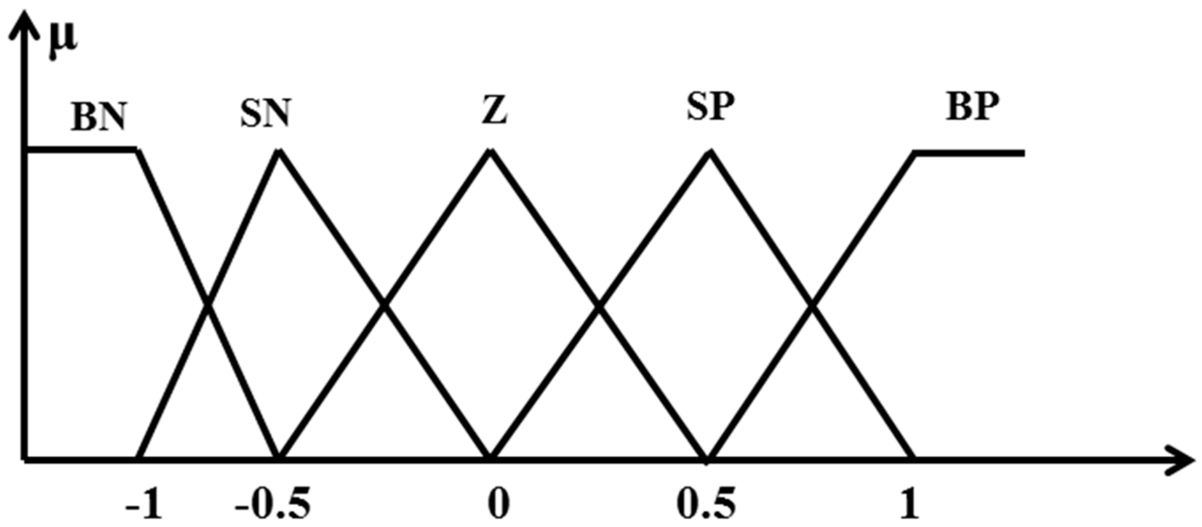
3. Type II Fuzzy Controller

In a type II fuzzy controller, the limitations of a type I controller, such as exhibiting the crisp value from the incurred two-dimensional membership functions (MFs), are eliminated. A T2-FPID controller is implemented for the LFC study as a secondary regulator in this work, and the scaling factors are also perceived. The MFs used in the type II fuzzy systems are three-dimensional and are created with an upper MF and lower MF combination like that in a type 1 fuzzy system [25]. In this work, the ACE and the change in the ACE are given as input variables to the T2-FPID controller, and the fuzzifier unit converts them into a 3D representation and then transfers them to the rule-base unit and the defuzzifier unit. The membership functions (MFs) perceived in this work for both error and change in error are five linguistic variables termed big positive (BP), small positive (SP), zero (Z), big negative (BN), and small negative (SN), as depicted in Figure 3. A Mamdani type of fuzzy engine is perceived, and the FLC output is calculated by using the defuzzification method of the center of gravity. The two-dimensional FLC rule base is noted in Table 1. The structure of the T2-FPID controller is shown in Figure 4. The parameters K1 and K2 are scaling factors, and the gains of the PID are indicated with KP, KI, and KD, and N represents the filter coefficient.
However, parameters such as scaling factors, filter, and PID gains are optimally rendered with the WCA mechanism subjected to the time domain objective index of the ITAE given in Equation (2), where t represents the simulation time; parameters Δ f 1 and Δ f 2 indicate variations in the frequency of area 1 and area 2, respectively; and Δ P t i e 12 represents deviations in the tie-line power flow.
J I T A E = 0 t t * ( Δ f 1 + Δ P t i e 12 + Δ f 2 ) d t

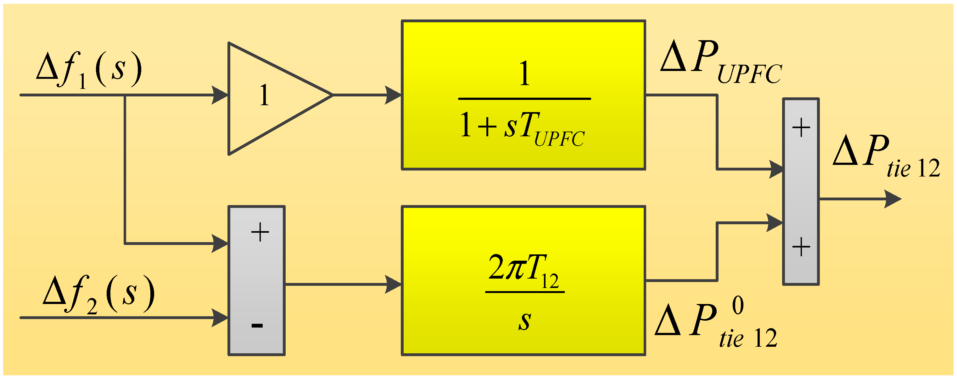
4. Territorial Strategy of the SMES-UPFC

In the course of greater load disturbances, the secondary regulator is not passable enough to handle the system deviations. So, a territorial control strategy is implemented in this work in order to sustain system stability even in worst-case scenarios.

4.1. UPFC

Through an intended path, real and reactive power can be diverted by the UPFC. Moreover, they are multivariable FACTS devices that can regulate system parameters and thereby enhance the interline flow of power. The combination of an SSSC and a STATCOM with a common DC link forms the device UPFC. Without additional sources, the UPFC can facilitate real power compensation and also have the capability to absorb/generate real power and hence enhance system stability. The UPFC structure implemented in this work as a damping controller is shown in Figure 5 [21].

4.2. SMES

An SMES play a handy role in providing real power during line outages at the load end. These devices store energy in the form of a DC magnetic field by passing current through the conductor wound around the magnet, which is maintained at cryogenic temperature to impart a lossless nature. SMES devices get charged up during off-peak demands and discharged at the time of power shortages. They have the feasibility to enhance the line capacity by softening inter-area deviations. An SMES acts as an excellent spinning reserve to meet the sudden demands on the system, thereby diminishing frequency fluctuations. An SMES has the capability of huge storage capacity, and its low charge/discharge time makes its application possible for LFC study. The mathematical model of the SMES [26] used in work is given in Equation (3).
G S M E S = K S M E S 1 + s T S M E S

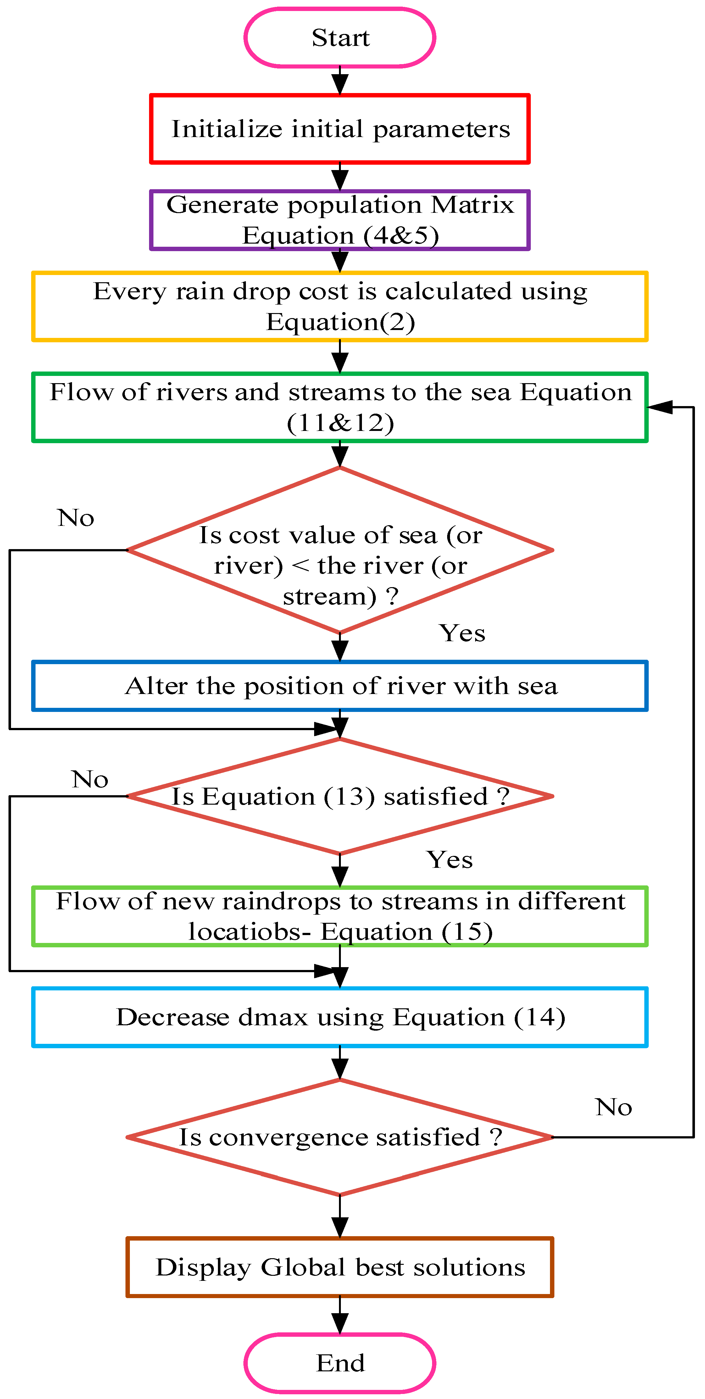
5. Water Cycle Algorithm

Eskandar et al. [27] in the year 2012 proposed this WCA strategy inspired from the continuous water movement. Since then, this algorithm has been widely used by researchers to solve non-linear constrained optimization problems and also engineering optimizations. In this water cycle process, water collects at the banks of streams and rivers. Later, these rivers/streams continue to join the sea. Moreover, this strategy possesses strength to obtain minimum or maximum index values accurately within a few iterations. So, in this work, this WCA approach is followed to retrieve the parameters of the secondary regulator optimally so that variations in frequency are reduced. In this WCA, rivers or streams act as the initial population and the sea is the global best.
Every raindrop (RD) is generated as an array of N v a r acts as a solution for the problem initialized as
R D i = X i = [ x 1 , x 2 x N v a r ]
P o p u l a t i o n   R D = [ R D 1 - - - R D i - - - R D N P O P ]
Later, every RD cost is evaluated by using the ITAE equation, and the gains of the T2-FPID are initialized, subjected to the constraints modeled as follows:
K 1 M i n K 1 K 1 M a x
K 2 M i n K 2 K 2 M a x
K P M i n K P K P M a x
K I M i n K I K I M a x
K D M i n K D K D M a x

5.1. Streams Flow into the River or Rivers Flow into the Sea

The water in the streams tries to flow toward the river, and in the same way, the water in the rivers flows toward the sea. The position of streams and rivers is updated using the following expressions:
P S t r e a m ( t + 1 ) = P S t r e a m ( t ) + r a n d ( ) × k × ( P R i v e r ( t ) P S t r e a m ( t ) )
P R i v e r ( t + 1 ) = P R i v e r ( t ) + r a n d ( ) × k × ( P S e a ( t ) P R i v e r ( t ) )
Here, k representing the constant usually takes a value between 1 and 2, r a n d ( ) is a random number from 0 to 1, and t indicates iterations. In case the objective index developed by the stream is better than that of the river, then the positions of streams and rivers are altered. A similar strategy is applicable for rivers and the sea.

5.2. Evaporation and Rain

This loop has a vital role in the searching mechanism of WCA. This evaporation and rain loop is intended to avoid getting trapped into the local optima. This loop keeps this WCA approach in a hierarchical position compared to other techniques. The process of evaporation terminates if
| P S e a P R i v e r | < d m a x
d m a x ( t + 1 ) = d m a x ( t ) ( d m a x / ( t ) / i t e r . m a x )
After the process of evaporation ends, immediately the process of rain starts:
P S t r e a m ( t + 1 ) = P S e a ( t ) + V   X   r a n d ( 1 , N v a r )
The searching rate nearer to the sea is indicated with V. The global best solutions are displayed immediately when the main loop reaches the maximum iterations. The procedural flow of WCA is depicted in Figure 6.

6. Results and Discussion

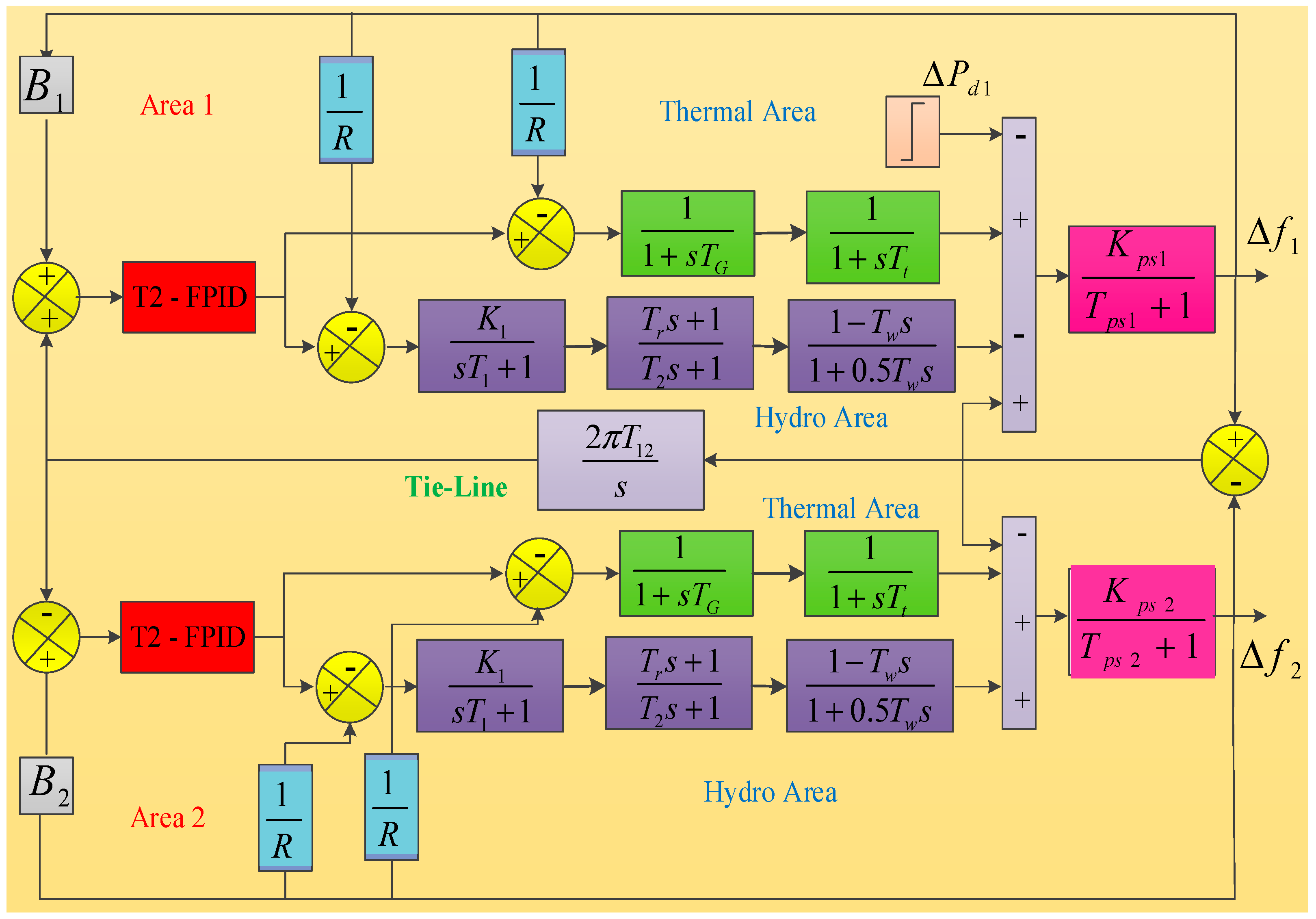
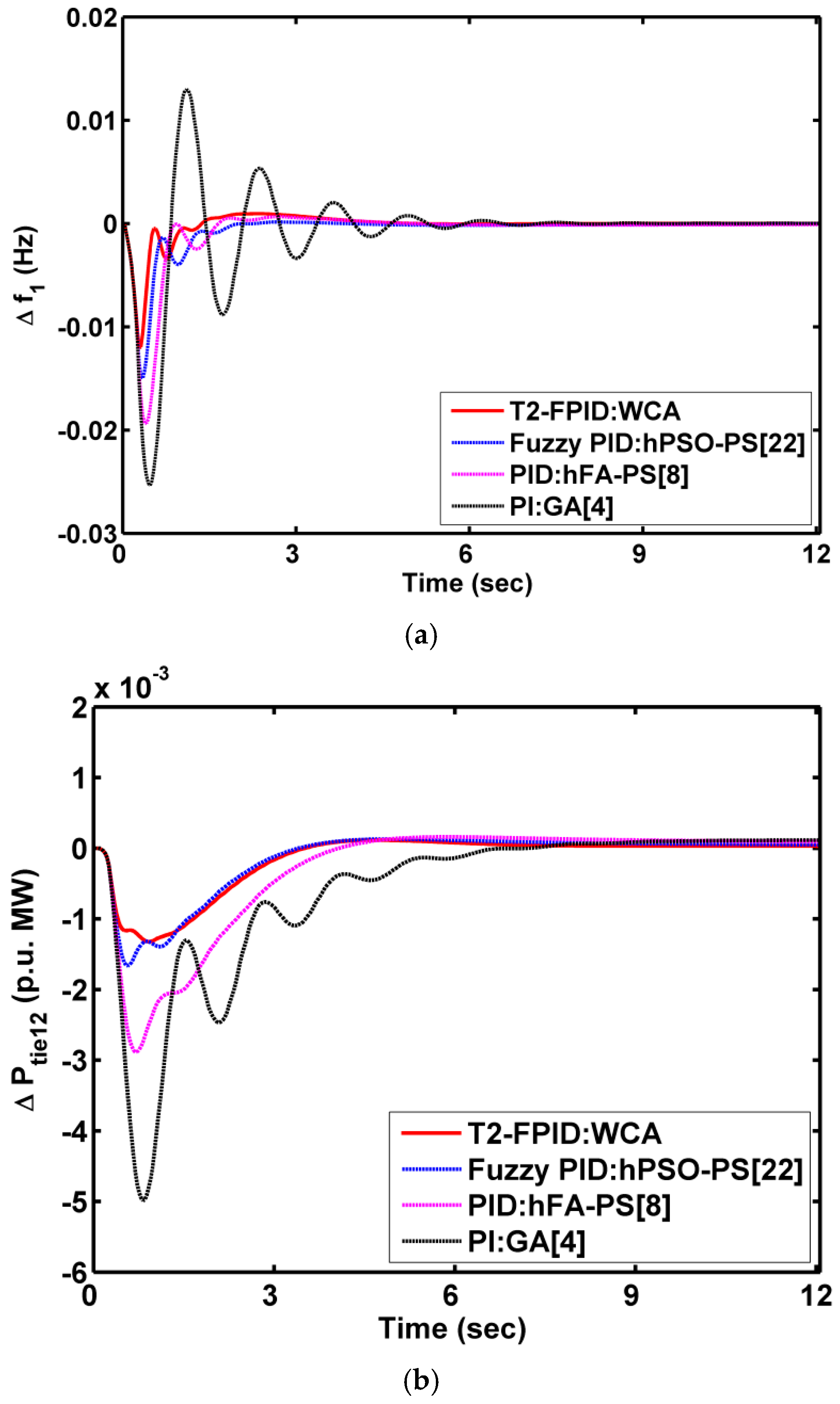
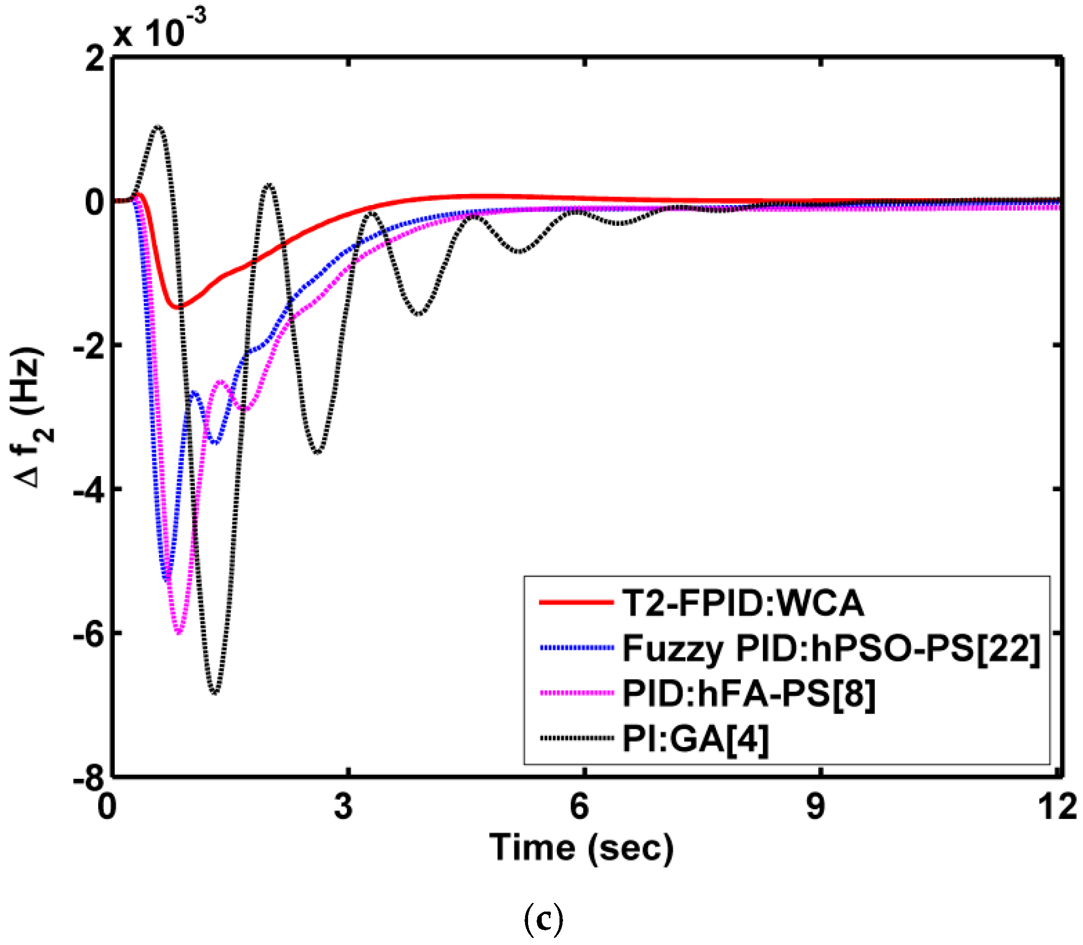
6.1. Case 1: Performance Analysis of Test System 1

To notice the execution of the presented regulator WCA-optimized T2-FPID, a conventional hydro-thermal dual-area system is considered by perceiving area 1 with a disturbance of 10% SLP. However, controlling strategies reported in the early and recent literature, such as PI, a PID tuned with the respective GA [4], and hFA-PS [8] algorithms along with a fuzzy PID optimized with hPSO-PS [22], are implemented to demonstrate WCA-based T2-FPID control efficacy. The system nature under these controllers is assessed and compared in Figure 7, and respective responses’ settling times along with regulator optimal parametric gains are noted in Table 2. Gathering from Figure 7 and interpreting the settling times noted in Table 2, it is confirmed that the presented WCA-based T2-FPID shows remarkable performance in damping out frequency and inter-area power flow deviations. Hence, the presented WCA-based T2-FPID approach is more dominating and outperforms the methodologies that are listed in the literature because of the inheritance of the evaporation and rain loop in the WCA mechanism to avoid solution divergence and because the usage of 3D MFs in the T2-FPID regulator enhances the degree of freedom.

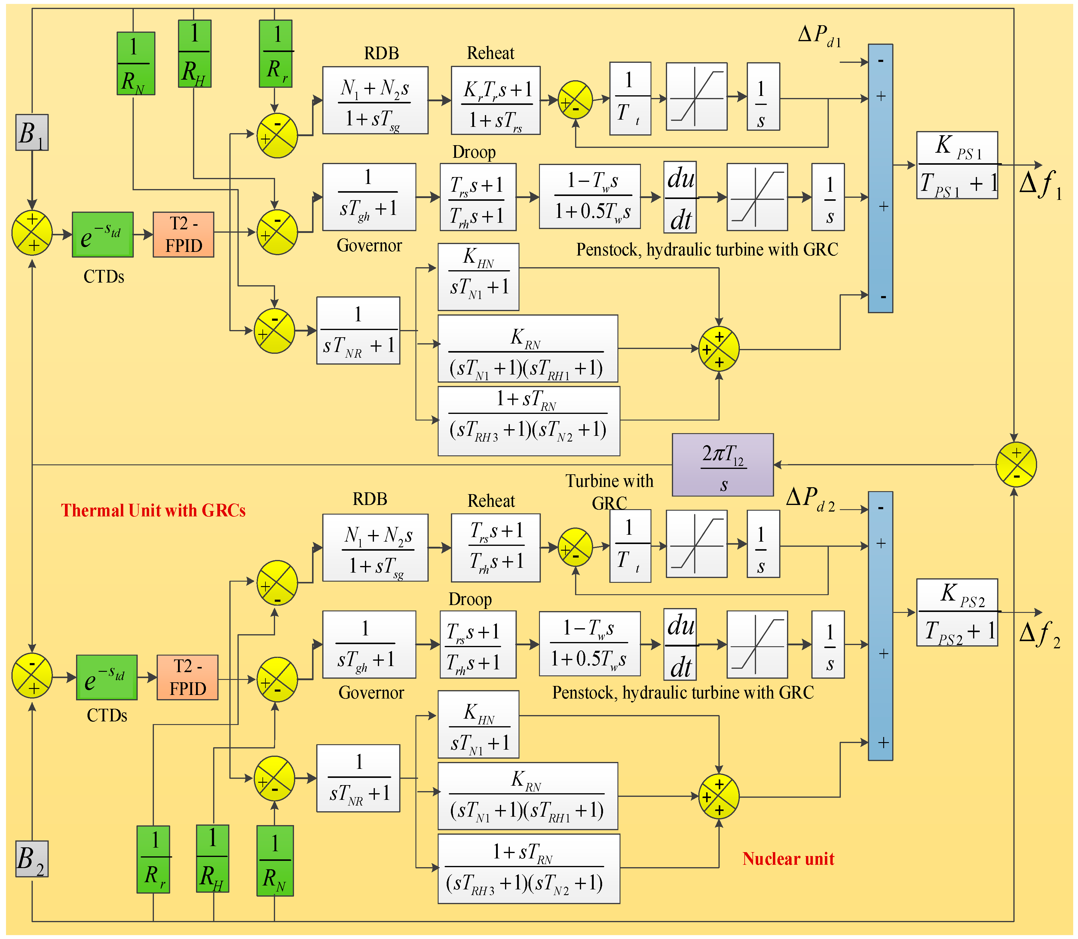
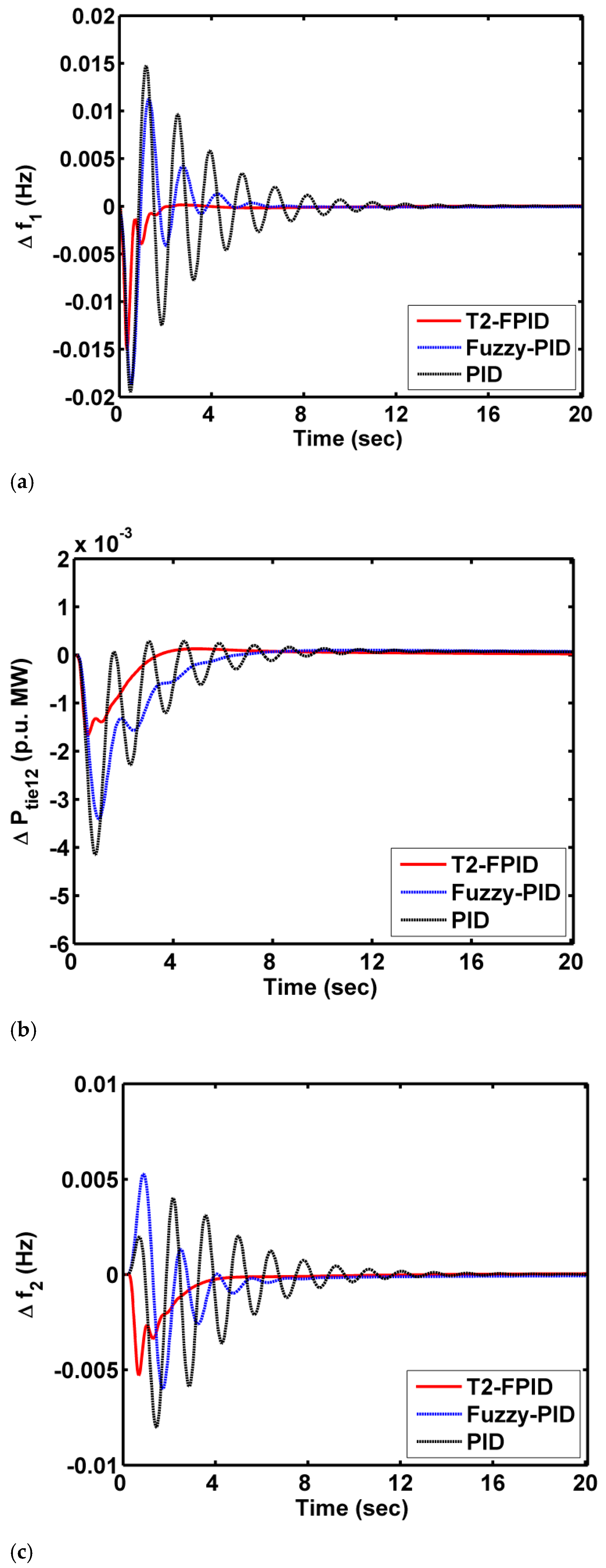
6.2. Case 2: Performance Analysis of Test System 2 without CTD Consideration

Later, the presented T2-FPID regulator is also implemented in the MATHN model, named test system 2 in this paper, depicted in Figure 2. The PID, fuzzy PID, and T2-FIPD controllers are used as secondary regulators optimized with the WCA mechanism one after the other, and the behavior of the system is assessed upon laying area 1 with a disruption of 10% SLP. A performance comparison of these controllers on the MATHN system without taking CTDs into consideration is shown in Figure 8. Visualizing Figure 8, the T2-FPID is more dominating than a conventional PID and fuzzy PID in dampening deviations and also providing the responses to reach a steady condition.

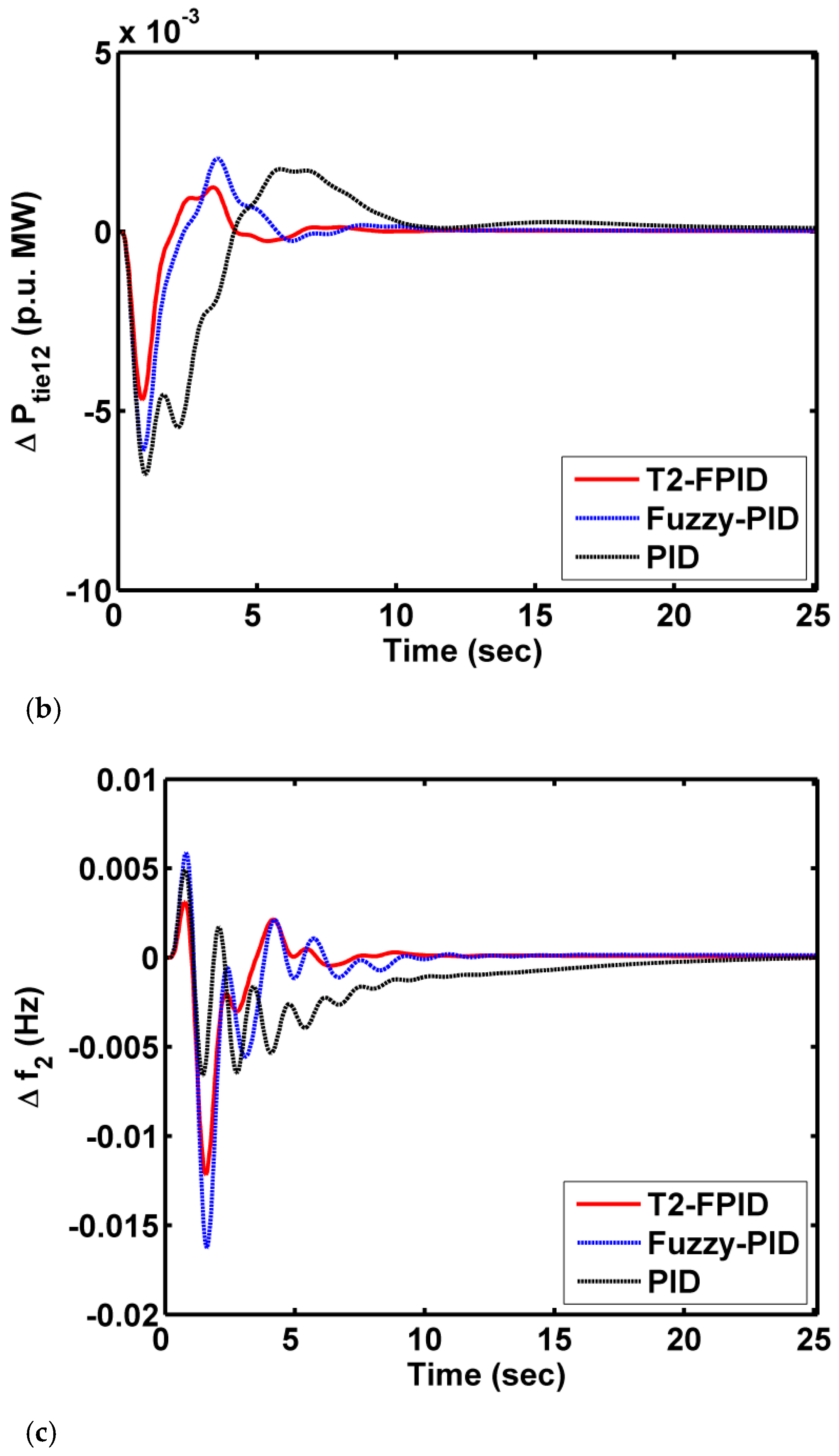
6.3. Case 3: Performance Analysis of Test System 2 with CTD Consideration

In this case, the MATHN model is used with practicality constraints of CTDs and the behavior of the system is monitored under the supervision of a PID, fuzzy PID, and T2-FPID based on the WCA mechanism one at a time. Figure 9 depicts the comparative analysis of these controllers on the MATHN system with CTDs and reveals that even when the system is considered with CTDs, the presented T2-FPID outperforms other controllers. Optimal parameters of controllers and numerical results of the system responses are noted in Table 3 and Table 4.

6.4. Case 4: Demonstrating the Impact of CTDs on Test System 2

To showcase the impingement of CTDs on MATHN system performance, MATHN system responses under the governing of the WCA-optimized T2-FPID regulator are compared in Figure 10, without and with adopting CTDs. From the above cases, as the T2-FPID controller is proven to be the most dominating, only the system responses with this controller have been considered in this case. From Figure 10, CTDs have a considerable effect on system stability. Reponses are much deviated upon considering CTDs with the system compared to the case of not taking them into account. With the delay in communication between sensors situated at distant locations and power generation units, altering of the turbine set point valve position will get delayed. Due to this, there will be widening of the real power mismatch, leading to more variations in system dynamics. However, CTDs are needed to be taken into account while assessing the performance of interconnected models. While doing so, the designed regulator can handle the system deviations more effectively compared to the case of a controller designed for a system not taking CTDs into account.

6.5. Case 5: Performance Assessment of the UPFC-SMES on Test System 2

Later, the mechanism of a territorial control scheme is implemented for test system 2 under governing of the WCA-tuned T2-FPID regulator to improve the system dynamical nature. First, only SMES devices are merged in each area and the system performance is assessed. Later, a UPFC device is placed in the inter-area along with SMES device positions, which are kept unchanged, and the responses are shown in Figure 11. As shown in Figure 11, there is an enhancement in the performance of the MATHN model with the UPFC-SMES strategy. This is possible only because of the nature of the SMES in meeting a sudden load demand and the UPFC in regulating the inter-area power flow.

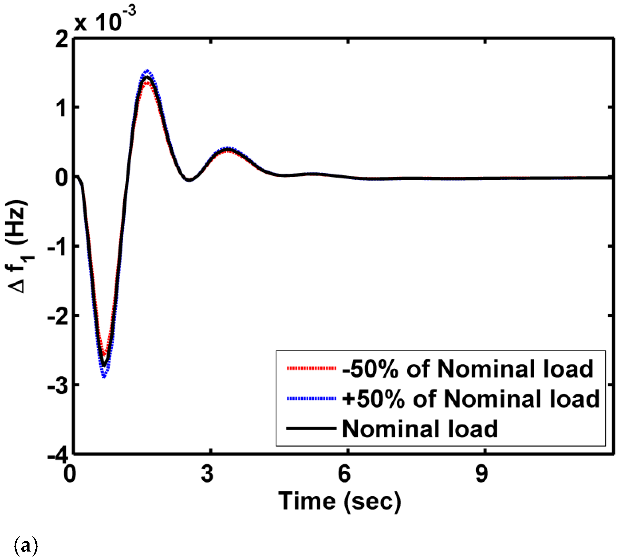
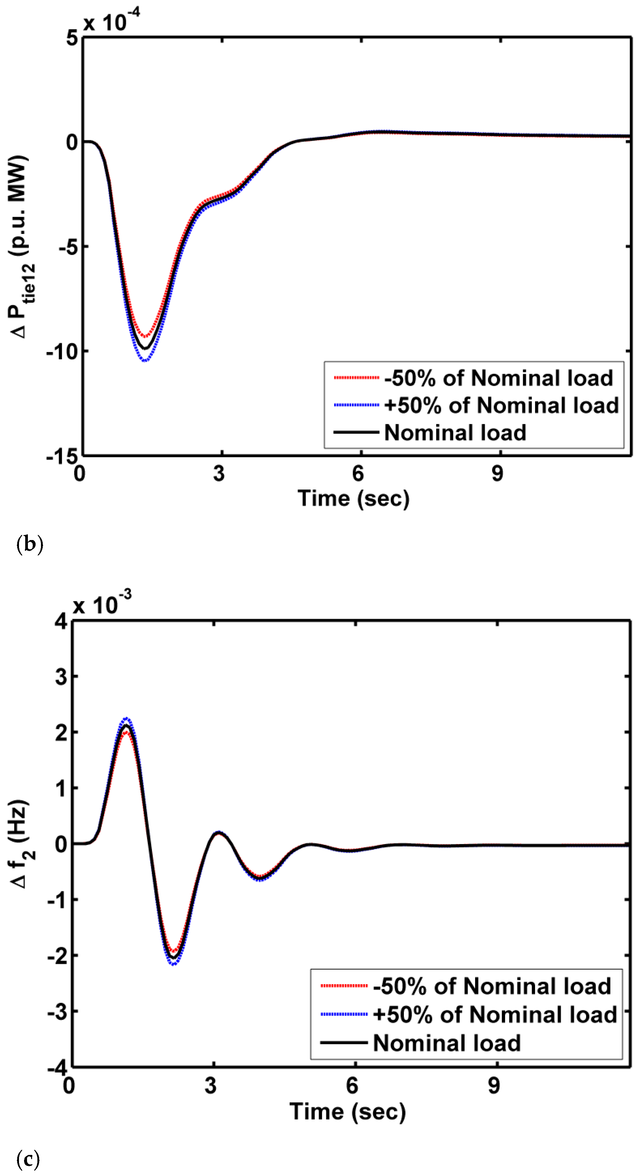
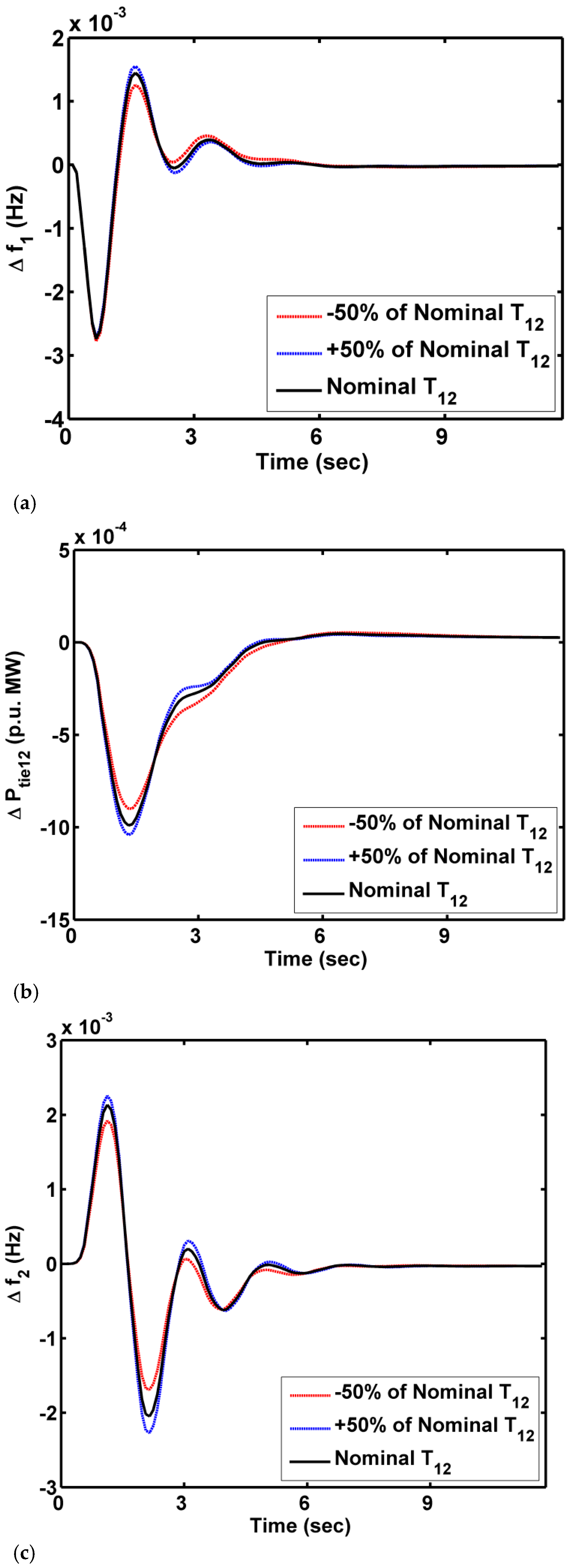
6.6. Case 6: Sensitivity Analysis

Further, the MATHN model is subjected to different load variations and the system parameter of the tie-line coefficient in the range of ±50% from the nominal value to validate the robustness of secondary and territorial coordinated control mechanisms. The responses for testing the robustness are shown in Figure 12 and Figure 13. From this case, it is finalized that the system dynamical behavior is not much affected, even if the system is subjected to parameter deviations and load variations.

7. Conclusions

This paper addressed the potentiality of a WCA-optimized T2-FPID controller in mitigating the frequency and interline flow of power fluctuations in the MATHN power system. However, the efficacy of the T2-FPID is revealed by comparing its performance with a fuzzy PID and a conventional PID. Further, the performance of the MATHN power system is scoped by considering it without and with CTDs. The presented T2-FPID regulator enhances the performance index value by 35.6% with a fuzzy PID and 42.2% with a traditional PID in the case of not considering CTDs and by 23.3% with a fuzzy PID and 31.4% with a traditional PID in the case of considering CTDs. The impingement of CTDs on the MATHN system is showcased and justified. Subsequently, implementing the territory control of the UPFC-SMES scheme under the governing of a WCA-tuned type II fuzzy regulator shows remarkable enhancement in mitigation of variations. Later, a robustness test is performed and it reveals the robustness of the presented secondary and territory regulation schemes. Moreover, the presented WCA-based type II fuzzy regulator is applied on the widely accepted test system of DAHT and the presented approach outperforms other controllers such as the PI and PID tuned with GA and hFA-PS techniques, along with the fuzzy PID tuned with hPSO-PS mentioned in the recent literature.

Author Contributions

Conceptualization, C.N.S.K.; methodology, C.N.S.K. and B.S.G.; software, C.N.S.K., B.S.G. and C.R.R.; validation, C.N.S.K., B.S.G. and C.R.R.; formal analysis, C.N.S.K., B.S.G. and C.R.R.; investigation, C.N.S.K., B.S.G. and C.R.R.; resources, C.N.S.K., B.S.G., C.R.R., and M.B.; data curation, C.N.S.K., B.S.G. and C.R.R.; writing—review and editing, M.B., C.R.R. and H.S.R.; visualization, C.R.R.; supervision, C.N.S.K.; project administration, M.B., C.R.R. and Z.M.A.; funding acquisition, M.B., C.R.R., Z.M.A. and H.S.R. All authors have read and agreed to the published version of the manuscript.

Funding

This research received no external funding.

Institutional Review Board Statement

Not Applicable.

Informed Consent Statement

Not Applicable.

Data Availability Statement

Not Applicable.

Conflicts of Interest

The authors declare no conflict of interest.

Abbreviations

CTDCommunication time delay
DAHTDual-area hydro-thermal
DOFDegree of freedom
ESDsEnergy storage devices
FLCFuzzy logic controller
GSAGravitational search algorithm
GRCGeneration rate constraint
GWOGray wolf optimizer
HAEFAHybrid artificial field algorithm
ITAEIntegral time area error
LFCLoad frequency controller
MFsMembership functions
FOFractional order
MATHNMulti-area thermal-hydro-nuclear
PSPattern search
T2-FPIDType II fuzzy PID
SMESSuperconducting magnetic energy storage
SRSecondary regulator
PSOParticle swarm optimization
SLPStep load perturbation
GDBGovernor dead band
WCAWater cycle algorithm
UPFCUnified power flow controller

Appendix A

Test system 1 [4]:
Thermal units: Tg = governor time constant = 0.08 s; Tt = turbine time constant = 0.4 s; RT = governor regulation gain = 2.2 Hz/MW
Hydel units: K1 = governor gain = 1.0; T1 = governor time constant = 47.8 s; T2 = amplifier time constant = 0.524 s; Tr = amplifier reset time = 5.0 s; TW = turbine time constant = 1.0 s; RH = governor regulation gain = 2 Hz/MW
Test system 2 [21]:
Thermal units: N1 = 80 and N2 = 120, GDB parameters; Tsg = governor time constant = 0.06 s; Tr = turbine reheat time constant = 0.3 s; Tt = turbine time constant = 10.2 s
Hydel units: Tgh = governor time constant = 0.2 s; Trh = hydraulic amplifier time constant = 28.768 s; Tw = turbine time constant = 1.1 s
Nuclear units: TNR = nuclear reactor time constant = 0.26 s; KRN = reactor gain constant = 0.3; TRH1, TRH2, and TRH3 = low-pressure turbine time constants = 7 s, 6 s, and 10 s, respectively; TN1 and TN2 = high-pressure turbine time constants = 0.5 s and 9 s, respectively
SMES devices: KSMES = SMES gain constant = 0.9; TSMES = SMES time constant = 1 s

References

  1. Tungadio, D.H.; Sun, Y. Load frequency controllers considering renewable energy integration in power system. Energy Rep. 2019, 5, 436–454. [Google Scholar] [CrossRef]
  2. Elgerd, O.I.; Fosha, C.E. Optimum mega-watt frequency control of multi-area electric energy systems. IEEE Trans. Power Appl. Syst. 1970, 89, 556–563. [Google Scholar] [CrossRef]
  3. Nanda, J.; Mishra, S.; Saikia, L.C. Maiden application of bacterial foraging based optimization technique in multi-area automatic generation control. IEEE Trans Power Syst. 2009, 24, 602–609. [Google Scholar] [CrossRef]
  4. Chandrakala, K.R.M.V.; Balamurugan, S.; Sankaranarayanan, K. Variable structure fuzzy gain scheduling based load frequency controller for multi-source multi area hydro thermal system. Int. J. Electr. Power Energy Syst. 2013, 53, 375–381. [Google Scholar] [CrossRef]
  5. Shankar, R.; Kalyan, C.; Ravi, B. Impact of energy storage system on load frequency control for diverse sources of interconnected power system in deregulated power environment. Int. J. Electr. Power Energy Syst. 2016, 79, 11–26. [Google Scholar] [CrossRef]
  6. Guha, D.; Roy, P.K.; Banerjee, S. Load frequency control of large scale power system using quasi-oppositional grey wolf optimization algorithm. Eng. Sci. Technol. Int. J. 2016, 19, 1693–1713. [Google Scholar] [CrossRef] [Green Version]
  7. Naga, C.S.K.; Sambasivarao, G. Frequency and voltage stabilization in combined load frequency control and automatic voltage regulation of multi area system with hybrid generation utilities by AC/DC links. Int. J. Sustain. Energy 2020, 39, 1009–1029. [Google Scholar] [CrossRef]
  8. Sahu, R.K.; Panda, S.; Padhan, S. A hybrid firefly algorithm and pattern search technique for automatic generation control of multi area power systems. Int. J. Electr. Power Energy Syst. 2015, 64, 9–23. [Google Scholar] [CrossRef]
  9. Raju, M.; Saikia, L.C.; Sinha, N. Automatic generation control of a multi-area system using ant lion optimizer algorithm based PID plus second order derivative controller. Int. J. Electr. Power Energy Syst. 2016, 80, 52–63. [Google Scholar] [CrossRef]
  10. Nosratabadi, S.M.; Bornapour, M.; Gharaei, M.A. Grasshopper optimization algorithm for optimal load frequency control considering predictive functional modified PID controller in restructured multi-resource multi-area power system with redox flow battery units. Control Eng. Pract. 2019, 89, 204–227. [Google Scholar] [CrossRef]
  11. Rahman, A.; Saikia, L.C.; Sinha, N. Automatic generation control of an unequal four-area thermal system using biogeography based optimized 3DOF-PID controller. IET Gener. Transm. Distrib. 2016, 10, 4118–4129. [Google Scholar] [CrossRef]
  12. Pradhan, P.C.; Sahu, R.K.; Panda, S. Firefly algorithm optimized fuzzy PID controller for AGC of multi-area multi-source power systems with UPFC and SMES. Eng. Sci. Technol. Int. J. 2016, 19, 338–354. [Google Scholar] [CrossRef] [Green Version]
  13. Tasnin, W.; Saikia, L.C. Comparative performance of different energy storage devices in AGC of multi-source system including geothermal power plant. J. Renew. Sustain. Energy 2018, 10, 024101. [Google Scholar] [CrossRef]
  14. Arya, Y. A new optimized fuzzy FOPI-FOPD controller for automatic generation control of electric power systems. J. Frankl. Inst. 2019, 356, 5611–5629. [Google Scholar] [CrossRef]
  15. Nayak, J.R.; Shaw, B.; Sahu, B.K. Application of adaptive SOS (ASOS) algorithm based interval type-2 fuzzy-PID controller with derivative filter for automatic generation control of an interconnected power system. Eng. Sci. Technol. Int. J. 2018, 21, 465–485. [Google Scholar] [CrossRef]
  16. Naga, C.S.K.; Sambasivarao, G. Coordinated SMES and TCSC damping controller for load frequency control of multi area power system with diverse sources. Int. J. Electr. Eng. Inform. 2020, 12, 747–769. [Google Scholar]
  17. Sahu, R.K.; Panda, S.; Padhan, S. A novel hybrid gravitational search and pattern search algorithm for load frequency control of nonlinear power system. Appl. Soft Comput. 2015, 29, 310–327. [Google Scholar] [CrossRef]
  18. Kalyan, C.N.S.; Suresh, C.V. Differential evolution based intelligent control approach for LFC of multiarea power system with communication time delays. In Proceedings of the 2021 International Conference on Computing, Communication, and Intelligent Systems, Noida, India, 19–20 February 2021; pp. 868–873. [Google Scholar] [CrossRef]
  19. Saha, A.; Saikia, L.C. Renewable energy source- based multiarea AGC system with integration of EV utilizing cascade controller considering time delay. Int. Trans. Electr. Energy Syst. 2018, 29, e2646. [Google Scholar] [CrossRef] [Green Version]
  20. Naga, C.S.K.; Sambasivarao, G. Combined frequency and voltage stabilization of multi-area multi source system by DE-AEFA optimized PID controller with coordinated performance of IPFC and RFBs. Int. J. Ambient. Energy 2020. [Google Scholar] [CrossRef]
  21. Kalyan, C.N.S. UPFC and SMES based coordinated control strategy for simultaneous frequency and voltage stability of an interconnected power system. In Proceedings of the 2021 1st International Conference on Power electronics and Energy, Bhubaneswar, India, 2–3 January 2021. [Google Scholar] [CrossRef]
  22. Sahu, R.K.; Panda, S.; Sekhar, G.T.C. A novel hybrid PSO-PS optimized fuzzy PI controller for AGC in multi area interconnected power systems. Int. J. Electr. Power Energy Syst. 2015, 64, 880–893. [Google Scholar] [CrossRef]
  23. Gupta, D.K.; Jha, A.V.; Appasani, B.; Srinivasulu, A.; Bizon, N.; Thounthong, P. Load frequency control using hybrid intelligent optimization technique for multi-source power systems. Energies 2021, 14, 1581. [Google Scholar] [CrossRef]
  24. Kalyan, C.H.N.S.; Rao, G.S. Impact of communication time delays on combined LFC and AVR of a multi-area hybrid system with IPFC-RFBs coordinated control strategy. Prot. Control Mod. Power Syst. 2021, 6, 7. [Google Scholar] [CrossRef]
  25. Sahu, P.C.; Prusty, R.C.; Panda, S. Approaching hybridized GWO-SCA based type-II fuzzy controller in AGC of diverse energy source multi area power system. J. King Saud Univ. Eng. Sci. 2020, 32, 186–197. [Google Scholar] [CrossRef]
  26. Naga, C.S.K.; Sambasivarao, G. Performance comparison of various energy storage devices in Combined LFC and AVR of multi area system with renewable energy integration. Int. J. Renew. Energy Res. 2020, 10, 933–944. [Google Scholar]
  27. Eskandar, H.; Sadollah, A.; Bahereininejad, A.; Hamdi, M. Water Cycle algorithm- a novel meta-heuristic optimization method for solving constrained engineering optimization problems. Comput. Struct. 2012, 110, 151–166. [Google Scholar] [CrossRef]
Figure 1. Dual-area conventional hydro-thermal plant (DAHT) (test system 1) [24].
Energies 14 05387 g001
Figure 2. Model of a MATHN plant with CTDs (test system 2) [21].
Energies 14 05387 g002
Figure 3. MFs implemented for the FLC.
Energies 14 05387 g003
Figure 4. Structure of the T2-FPID controller.
Energies 14 05387 g004
Figure 5. UPFC damping controller [21].
Energies 14 05387 g005
Figure 6. WCA approach flowchart.
Energies 14 05387 g006
Figure 7. Responses for case 1: (a) Δ f 1 (b) Δ P t i e 12 and (c) Δ f 2 .
Energies 14 05387 g007aEnergies 14 05387 g007b
Figure 8. Responses for case 2: (a) Δ f 1 (b) Δ P t i e 12 and (c) Δ f 2 .
Energies 14 05387 g008
Figure 9. Responses for case 3: (a) Δ f 1 (b) Δ P t i e 12 and (c) Δ f 2 .
Energies 14 05387 g009aEnergies 14 05387 g009b
Figure 10. Responses for case 4: (a) Δ f 1 (b) Δ P t i e 12 and (c) Δ f 2 .
Energies 14 05387 g010
Figure 11. Responses for case 5: (a) Δ f 1 (b) Δ P t i e 12 and (c) Δ f 2 .
Energies 14 05387 g011aEnergies 14 05387 g011b
Figure 12. Responses for case 6 for load variations: (a) Δ f 1 (b) Δ P t i e 12 and (c) Δ f 2 .
Energies 14 05387 g012aEnergies 14 05387 g012b
Figure 13. Responses for case 6 for variations in the tie-line coefficient: (a) Δ f 1 (b) Δ P t i e 12 and (c) Δ f 2 .
Energies 14 05387 g013
Table 1. FLC system input and output rules.
ACEΔACE
BNSNZSPBP
BNBNBNBNSNZ
SNBNBNSNZSP
ZBNSNZSPBP
SPSNZSPBPBP
Table 2. Optimal controller gains and settling times of responses for case 1.
AlgorithmWCA:
T2-FPID
hPSO-PS:
Fuzzy PID [22]
hFA-PS:
PID [8]
GA: PI [4]
Optimal gainArea 1K1 = 0.0759
K2 = 0.0377
KP = 1.1288
KI = 0.1584
KD = 0.5725
KP = 1.0366
KI = 0.2098
KD = 0.4317
KP = 1.1231
KI = 0.3665
KD = 0.3821
KP = 0.7308
KI = 0.1844
Area 2K1 = 0.1890
K2 = 0.0908
KP = 1.1056
KI = 0.1712
KD = 0.4070
KP = 1.0900
KI = 0.2521
KD = 0.3502
KP = 1.1673
KI = 0.1056
KD = 0.3276
KP = 0.6877
KI = 0.1722
ITAE × 10−43.3511.2926.8867.49
Settling time (s)Δf14.655.166.9210.95
Δf25.837.899.8710.42
ΔPtie125.086.809.4810.21
Table 3. Optimal controller gains for test system 2 in various cases.
ParametersWithout CTDsWith CTDs
T2-FPIDFuzzy PIDPIDT2-FPIDFuzzy PIDPID
Area 1K1 = 0.0685
K2 = 0.0962
KP = 1.8995
KI = 0.3503
KD = 0.6172
KP = 1.2095
KI = 0.3167
KD = 0.4756
KP = 1.1048
KI = 0.2040
KD = 0.3010
K1 = 0.0873
K2 = 0.0900
KP = 1.2040
KI = 0.4098
KD = 0.8930
KP = 0.9812
KI = 0.1294
KD = 0.8226
KP = 0.8297
KI = 0.2454
KD = 0.7272
Area 2K1 = 0.0990
K2 = 0.0355
KP = 1.2156
KI = 0.2911
KD = 0.7691
KP = 0.9990
KI = 0.2988
KD = 0.3765
KP = 1.2136
KI = 0.3139
KD = 0.6754
K1 = 0.0158
K2 = 0.0776
KP = 1.0639
KI = 0.3822
KD = 0.7819
KP = 1.0189
KI = 0.2194
KD = 0.9335
KP = 0.9867
KI = 0.3125
KD = 0.6999
Table 4. Settling time of responses in various cases for test system 2.
Settling Time (s)Without CTDsWith CTDs
PIDFuzzy PIDT2-FPIDPIDFuzzy PIDT2-FPIDT2-FPID with RFBsT2-FPID with UPFC-RFBs
Δf114.068.725.22223.0114.0911.828.3645.44
ΔPtie1215.9110.969.0522.5115.8212.588.0315.639
Δf215.429.7256.39822.2814.1411.938.6416.54
Publisher’s Note: MDPI stays neutral with regard to jurisdictional claims in published maps and institutional affiliations.

