
Examining Thermal Management Strategies for a Microcombustion Power Device


Mechanical Engineering Department, Rowan University, 201 Mullica Hill Rd., Glassboro, NJ 08028, USA
*
Author to whom correspondence should be addressed.
Energies 2021, 14(19), 6322; https://0-doi-org.brum.beds.ac.uk/10.3390/en14196322
Submission received: 16 August 2021
/
Revised: 24 September 2021
/
Accepted: 29 September 2021
/
Published: 3 October 2021
(This article belongs to the Special Issue Advanced Thermal Energy Conversion and Management Technologies)
Abstract
:Microcombustion attracts interest with its promise of energy dense power generation for electronics. Yet, challenges remain to develop this technology further. Thermal management of heat losses is a known hurdle. Simultaneously, non-uniformities in heat release within the reaction regions also affect the device performance. Therefore a combination of thermal management strategies are necessary for further performance enhancements. Here, a bench top platinum nanoparticle based microcombustion reactor, coupled with thermoelectric generators is used. Methanol-air mixtures achieve room temperature ignition within a catalytic cartridge. In the current study, the reactor design is modified to incorporate two traditional thermal management strategies. By limiting enthalpic losses through the exhaust and reactor sides, using multi-pass preheating channels and heat recirculation, expected improvements are achieved. The combined strategies doubled the power output to 1.01 W when compared to the previous design. Furthermore, a preliminary study of catalyst distribution is presented to mitigate non-uniform catalytic activity within the substrate. To do this, tailored distribution of catalyst particles was investigated. This investigation shows a proof-of-concept to achieve localized control, thus management, over heat generation within substrates. By optimizing heat generation, a highly refined combustion-based portable power devices can be envisioned.
1. Introduction
As the worldwide need for electrical power grows, new, improved, and mobile methods of harvesting energy become more critical. Thermoelectric generation using catalyzed microcombustion is a strong candidate with many advantages. Rapid recharging is available with the use of hydrocarbon fuels. Devices can be compact and more energy dense compared to commonly used consumer batteries [1,2]. Additionally, battery disposal is eliminated, which prevents potential leaking of hazardous metals into the environment [3]. Fanciulli et al. [4] created a catalyst microcombustor about the size of a AA battery that produced 0.84 W, showing it is possible to produce power at similar scales to what we use in many consumer electronics. Microcombustion devices can vary in size, shape, and methodology as Ronney [5] discusses. They can range from miniaturized gas turbine to internal combustion engines that mimic current day bulk power devices [6,7]. With commercially available off-the-shelf components, Merotto et al. [8] were able to produce 9.86 W using catalytic combustion. Ahn et al. [9] shows that catalytic combustion allows for room temperature ignition and low steady state temperatures compared to gas-phase combustion. Another major benefit of microcombustion devices is that they typically include limited moving parts, making them robust in terms of durability [10,11]. While some disadvantages exist for widespread application, e.g., exhaust and fuel management, microcombustion contributes to the potential diversity of our future portable power sources. Despite their promise, there are thermal considerations that constrain their development.
The integral challenge for a thermoelectric generator (TEG) is optimizing the energy conversion from heat to electric power. Specifically, capturing and channeling the released combustion heat to the TEGs while limiting heat loss from the system. Thermal management is a key factor in overall device performance [8,12,13]. Current thermal efficiencies of such devices are around 2.75%. Several thermal management strategies exist to improve device performance. Heat recirculation is a common approach. Using computational models, Yan et al. [12] demonstrated that recirculating exhaust gasses is beneficial to combustion efficiency, increasing by approximately 9%. Aravind et al. [14] routed exhaust gasses between their combustion chamber and the TEGs, achieving an overall efficiency of 5.09%. Implementing a recirculating cup that uses exhaust gas to heat combustion chamber, Yadav et al. [13] was able to achieve 4.6% overall efficiency. Preheating inlet fuel/air mixtures has also been utilized extensively. Vijayan and Gupta [15] used a Swiss Roll design that passes hot exhaust gasses next to counter flowed inlet gasses. Merotto et al. [8] suspects that exploiting exhaust gasses could improve thermal to electric efficiency. Many other such traditional approaches have been studied to improve thermal management. Fernandez-Pello [16] discusses a number of microcombustion approaches and issues. However, there are unique aspects related to catalytic microcombustion that must be explored for local thermal management at the heat source.
Catalytic microcombustion uses catalyst material to achieve and sustain combustion within microcombustion devices. Platinum is the preferred catalyst for microcombustion for its activity with hydrocarbon fuels [17]. With catalytic combustion the heat release is not uniform throughout the substrate [11]. When using platinum catalyst for instance, researchers have noted hot zones or uneven heat distribution that reduce the overall device performance [9,18,19]. The hot zones negatively impact catalyst stability. To counter this effect, Luo et al. [20] shows that by placing catalyst in select regions, heat generation can be controlled to an extent. Similarly, Sakamoto et al. [21] revealed that by modifying the longitudinal catalyst density, a more uniform temperature distribution can be achieved. These studies, however, target single channels as opposed to multi-channel combustion common with catalytic cartridges. Therefore, catalyst distribution studies are often unique to the device in question, and depending on the device configuration, it is often challenging to study all thermal management strategies at once to combine the benefits of each.
This work pursued one new catalyst distribution and two traditional thermal management strategies, on a previously developed design [22]. While our previous efforts focused on developing a highly configurable catalytic cartridge based microcombustor, this work explores performance enhancements that can seed future developments. The traditional thermal management approaches were systematically examined and later combined for testing the eventual impact on device performance. Single and multi-pass preheating channels were studied to elevate the inlet temperatures for catalysis as well as reducing convective and radiative losses through reactor sides. A heat recirculation system (HRS) was integrated to route exhaust gases through the reactor-TEG interface to recover heat and limit exhaust heat loss. Finally, a tailored distribution of catalyst material was explored as a novel strategy for catalytic cartridges. The tailored distribution of platinum nanoparticles approach is unique within a three-dimensional system and enables further control over heat release across the substrate to mitigate catalyst degradation at the hot zones. The tailored catalyst distribution study provides a proof-of-concept for this alternate thermal management strategy. This last step does not represent an optimized device but indicates the strong influence of thermal management strategies on the design of a microcombustion device. This strategy also adds to the practical benefits of using cartridge-based designs.
2. Materials and Methods
The microcombustion experiments were conducted on a custom-built facility that integrated a catalytic cartridge placed within a reactor. The catalytic cartridge consisted of a cordierite substrate with multiple channels coated with Pt nanoparticles. Here we describe the material synthesis, sample preparation methods, and the subsequent modifications to the setup. The overall setup is identical to our previous paper by Guggilla et al. [22] and thus details of the methods are omitted for brevity. The descriptions of the setup is presented to justify the modifications studied and capture the salient features previously not presented. The materials and methods are only highlighted for the broader discussion of the results.
2.1. Material Synthesis, Sample Preparation, and Experimental Conditions
A cordierite monolith with 800 m wide square channels was used to host the catalyst. The catalytic substrate, also referred to as the catalytic cartridge, was a rectangular segment of cordierite monolith with dimensions, 28 mm × 26 mm × 9 mm. The overall dimensions and shape of the catalytic cartridge reflects the design evolution based on reactor and power requirements for this system [23], while keeping the base cordierite monolith the same. Thus, the monolith provides a unique advantage for this system in terms of scalability. The cartridge dimensions can be easily scaled to match the power needs of the device. The photo in Figure 1 displays an uncoated substrate that forms the catalytic cartridge. The channels were coated with platinum nanoparticles synthesized using methods described in Bonet et al. [24]. Platinum was chosen for its unique ability to ignite methanol-air mixtures at room temperature; as investigated in our previous works [23,25,26]. This way, Pt nanoparticles avoid the need for an additional ignition system. The as-synthesized Pt nanoparticles exhibited particle sizes = 9 ± 3.8 nm using XRD. The XRD results corroborated with SEM and TEM micrographs of deposited nanoparticles on the same substrate. The size distribution details are available elsewhere [23,25]. The nanoparticles were deposited in successive coatings to control loading. The deposition process consisted of pouring cleaned Pt nanoparticle solution through the channels and allowing the solvent to evaporate, one-side at a time. First, a single side of the substrate channels was coated followed by heating in a furnace for 20 min at 300 C. The same process was repeated for opposite sides by rotating the substrate each time to achieve multiple channel coatings, as illustrated in Figure 1. The substrates were labelled to indicate the number of sides coated and the number of depositions per side. For instance, “1SSC” represented a single side coated with a single coating. The coatings allowed a relative control over catalyst loading for the experiments. Multiple depositions per channel side were not considered for these experiments. Instead, a 2SSC substrate was used for all the experiments except for the tailored distribution experiments. This selection was made based on our previous studies showing material degradation for the higher substrate temperatures with long term operation. Similarly, air flow rate was selected after studying a range of flow rates and catalyst loading on the selected substrate and reactor configuration. Guggilla et al. [22] used an air flow rate of 8000 mL/min, however after extended operational time noticeable substrate temperature drop was recorded. Thus, air flow rate of 6000 mL/min was selected to limit peak temperatures within the substrate that lead to eventual catalytic substrate degradation.
2.2. Experimental Facility
The complete facility is depicted in Figure 2 along with the reactor module illustrations. Improved mounting was designed to provide uniform mechanical pressure across the TEG modules using springs. The figure shows the reactor assembly with modifications, clamped between two aluminum plates. Calipers were used to ensure the mechanical pressures were consistent across experiments. This standalone facility is supplied with compressed air and includes a methanol reservoir. The mount was also designed for rapid turn-around for repeated experiments. The stacked reactor holds many components of the system and has mirrored layers on the top and bottom. In order, from the center going outward, there is the reactor chamber that hosts the catalytic cartridge, the HRS, the TEG module, and the heat sink. The prepared substrate was placed in an aluminum reactor with two inlets and a single outlet. The inlets introduced premixed methanol and air into the catalytic substrate. The right side of Figure 2 shows the top views of the reactor components, after the modifications described later. Reactants entered the substrate from one end and exhausted from the other. Methanol (99.8% purity, Sigma Aldrich) was added to compressed ambient air using a glass bubbler to achieve near stoichiometric reactant mixture. Air was metered using a rotameter (Omega). K-Type thermocouples (TC, KMTXL-020G, Omega) were used to monitor the catalytic combustion temperatures and the subsequent thermal gradients. The key TC locations included: the hot and cold sides of the two TEG modules, the exhaust port, and within the center of the substrate. The reactor assembly was clamped with two spring loaded bolts. Calipers were used to ensure even pressure across the TEGs; and across experiments. The compressive force also limited leaks between the reactor layers. The temperature data was recorded using Labview DAQ and analyzed using MATLAB.
2.3. Modifications for Thermal Management
Three thermal management strategies were pursued to control the thermal gradients around and within the substrate, beyond the base facility presented in Guggilla et al. [22]. The primary objectives and approaches were: to reduce heat loss from the reactor sides using preheat channels, to increase the temperature gradient across the thickness of the TEG modules by improved mounting and heat recirculation, and to maximize catalytic activity across the substrate by achieving local control over catalyst loading. This last strategy constituted a strong departure from our previous works with a desire to achieve uniform distribution of catalyst. The design changes discussed here address these objectives. The modular design of the stacked reactor proved ideal for the subsequent reconfigurations without altering the reaction volume.
2.3.1. Heat Recirculation System (HRS)
The HRS was designed to promote heat transfer across the TEGs. The HRS is composed of two modules, one on top and bottom of the reactor. Its purpose was to increase the exhaust stream residence time. The increased residence time allows the exhaust to transfer the heat energy to the reactor before exiting the reactor. Figure 2 provides a schematic of the HRS modules composed of two 2.5 mm thick copper plates. The HRS routes the exhaust stream from the substrate to the bottom module before circulating through vertical slots in reactor wall to the top module. Multiple designs and configurations were studied to maximize the temperature gradient across the TEGs. The HRS units on top and bottom of the reactor were selected for the stacked reactor design. The substrate was thus enveloped by the HRS and the preheating channels to the sides.
2.3.2. Preheat Channels
The previous reactor design incorporated a single pass preheat channel to the sides of the substrate. While the channels achieved their desired goal of preheating the inlets, temperatures approaching 100 C were recorded at the exterior walls of the reactor. As a result, a second pass was designed by reorienting the inlets within the same base reactor design (while maintaining the reactor volume). A benefit to the preheating is the increased reactant temperature which aid in combustion by allowing the substrate to reach a steady state temperature sooner. At the same time, improved fuel conversion can be achieved as demonstrated in our previous study [23]. The final design is shown in the illustrations included with Figure 2.
2.3.3. Tailored Catalyst Distribution
A temperature map of the substrate was obtained using multiple TCs placed along specific channels. The map revealed low temperature zones near the substrate walls and towards the substrate exit. These non-uniformities are common within microcombustion systems and can impact device performance [17]. To achieve more uniform catalytic activity a tailored catalyst distribution approach was explored. The tailored distribution involved increasing the local catalyst loading at the substrate walls to increase temperatures and thus catalyst activity across the substrate channels. First, a 1SSC substrate was prepared. Next, additional coatings are added to a third of the substrate towards each wall. Figure 1 identifies the three sections of the substrate with dashed lines running from top to bottom of the substrate inlet. For comparison purposes, two substrates were prepared with tailored catalyst distribution: 214 and 113. The 214 substrate had thirds that were coated with: 2 sides coated, 1 side coated, and all four 4 sides coated, sequentially. The 113 substrate had thirds that were coated with: 1 side coated, 1 side coated, and 3 sides coated, sequentially. The additional catalyst loading towards the walls were used to promote catalytic activity. Tailored distribution of the catalyst loading along channel, i.e., in the flow direction, was not explored at this point.
3. Results
The microcombustion reactor facility exhibited room-temperature ignition of methanol-air mixtures with sustained catalytic activity. Catalytic activity, as measured by the substrate temperature, is a function of reactant flow rate and catalyst loading, as explored in our previous works [22,23]. Figure 3 presents temperature histories of thermocouple locations for the unmodified facility. These results are for an air flow rate of 6000 mL/min through a 2SSC substrate and correspond well to the previous conditions used with this facility. Experiments began when the reactants start to flow through the substrate. The highest temperatures were observed within the substrate center, denoted as . As discussed later, this temperature does not represent the temperature of the entire substrate. The initial peak in temperature at the center of the substrate after ignition gradually stabilizes to a steady overall substrate temperature. The top and bottom TEG modules were labelled 1 and 2, respectively, and distinguished by the solid and dashed lines within Figure 3. Both top and bottom TEG hot-side and cold-side temperatures were within 5 C of each other. For this unmodified reactor, the exhaust temperatures regularly approached ∼280 C. The rejection of high temperature exhaust prompted the described modifications. The retention of exhaust energy that would otherwise be lost can boost the temperature gradient across both the TEG modules by elevating the operating temperature of the reactor. Other aspects of the reactor design were targeted for modifications to better manage the thermal energy within the reactor. To evaluate the impact of the modifications, a flow rate of 6000 mL/min was selected for all subsequent experiments; which also corresponded to an optimal flow rate for a range of catalyst coatings and reactor stability. Substrates were prepared with two sides coated with a single deposition based on previous experimental conditions (i.e., 2SSC samples). With these conditions the unmodified reactor yielded an average T of 60 C. The subsequent modification study results are grouped by the thermal management approaches discussed earlier.
3.1. HRS Study
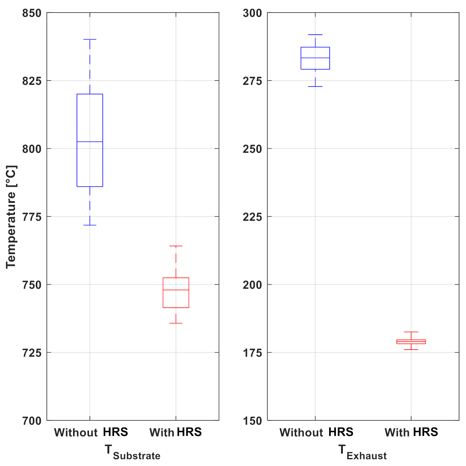
To limit the energy loss through the exhaust stream, heat recirculation modules were added to the reactor stack. The heat recirculation system was composed of copper plates with serpentine paths to redirect the heat from the exhaust to the hot side of the TEG modules. The HRS module stream was separated from the reactor region by copper sheets. Multiple designs were studied and compared. The designs varied in channel width and the number of passes across the reactor. These experiments were conducted with a single pass reactor design. The best performing design exhibited a ∼100 C decrease in exhaust temperature . Figure 4 compares key temperatures between the two setups. Instead of temperature histories that often drift over the experiment before stabilizing, Figure 4 presents a summary of experimental temperatures measured over a single experiment for an effective comparison. The energy extraction from the exhaust, however, came at the expense of a small decrease in substrate temperature. The decrease in temperature is localized to the substrate center and not indicative of the full substrate temperature distribution. The impact of HRS on the complete substrate was not investigated.
3.2. Preheat Channels Study
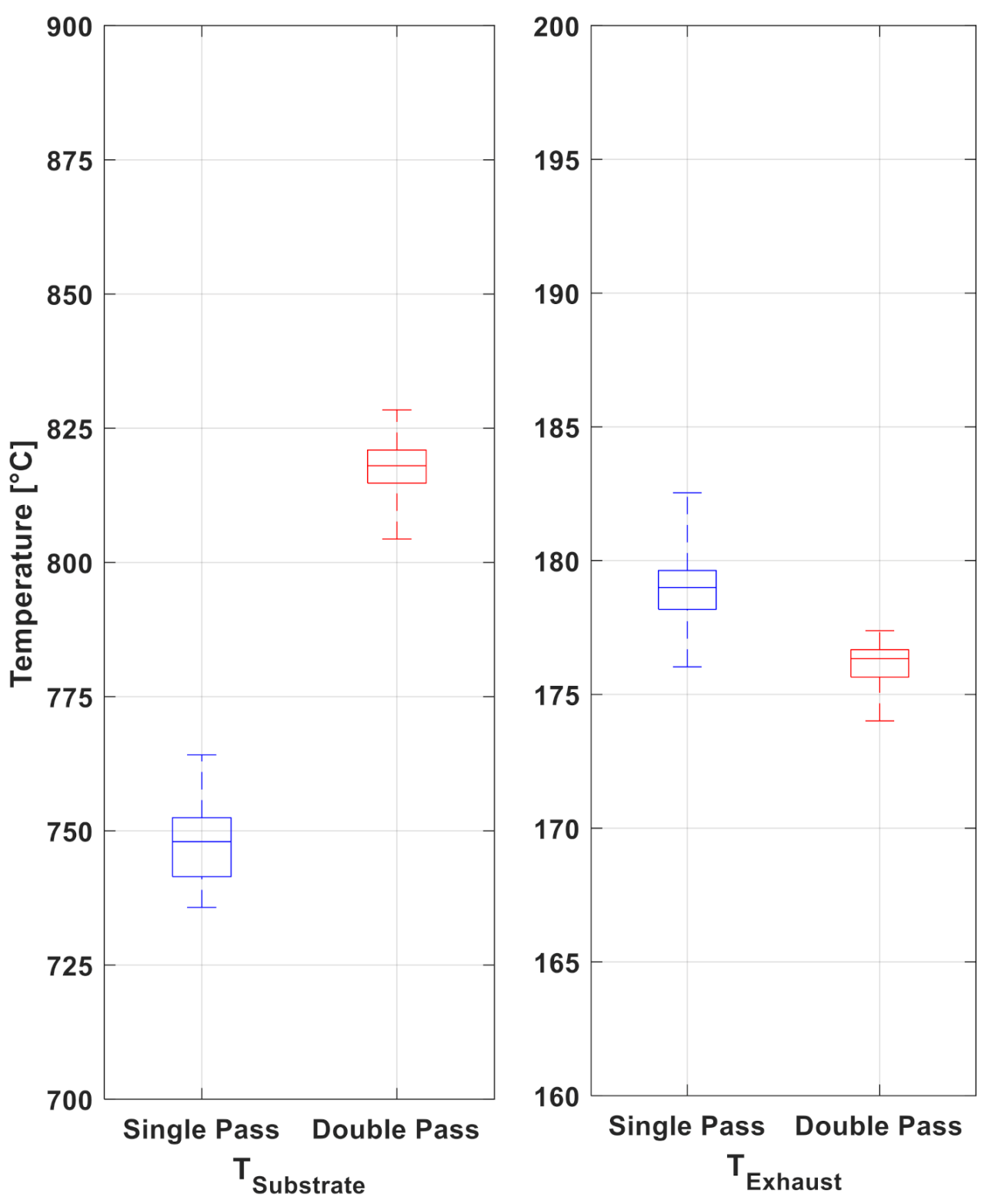
The modified reactor with double pass inlet streams was designed to increase the temperature of the incoming reactant and at the same time insulate the high substrate temperatures from the reactor exterior. The high temperatures observed within the single-pass preheat channel typically ignited the reactants prior to reaching the substrate. These localized hot-spots upstream of the reactor region promoted heat loss through the sides. Instead, the double pass created an additional barrier for heat transfer, at the same time providing the necessary preheating to the reactants. The improved preheating introduced higher temperature reactants to the substrate. Figure 5 compares the key temperatures for the single pass and double pass inlet reactors. The mean substrate temperature and the mean exhaust stream temperature with identical experimental conditions are compared. Again, key performance indicators are isolated for effective comparison. Both single and double pass reactors were tested with the implemented heat recirculation system; hence the lower overall exhaust temperatures for this set. The slight decrease in exhaust temperature is insignificant based on the experimental variability; yet included to demonstrate performance. The double pass reactor exhibited notably higher substrate temperature. It is important to note that the substrate volume was unaltered for this modification. In other words, the active region was unmodified for the preceding thermal management strategies. However, this is not the case with the next strategy that involves modification of the active region while keeping the volume unaltered.
3.3. Tailored Catalyst Distribution Study
3.3.1. Thermal Map
Previous work by Applegate et al. [23], and others, has demonstrated that the temperature within the substrate is nonuniform and thus reflects the uneven catalytic activity within the substrate. To capture the non-uniformity of the temperature, a thermal map of the substrate was generated using multiple thermocouples. This map not only demonstrates the non-uniformity but also shows the temperatures at locations where catalyst coatings can be adjusted in order to alter the overall substrate temperature. To generate the map, three thermocouples were placed through small holes located on the reactor sides. The TCs were inserted into the mid-plane of the substrate. Temperatures were recorded at various locations by manually shifting the TCs along the substrate channels. Figure 6 presents a thermal map of a 2SSC cordierite substrate during stable operation at 6000 mL/min. The thermal map was generated across the middle of the substrate and thus represents two-dimensional temperature non-uniformity of ; with high temperatures being represented by white and yellow regions and low temperature represented by dark red regions. As guided by the arrows, the top portion of the map is where reactants enter and the bottom is where the products exit the substrate. The highest temperatures were located at the entry region on top of the image and along the center of the substrates. The cool zones were confined to the sides near the substrate exit. The temperature profile matches the fluid profile of the reactant mixture entering the substrate with the highest velocities at the center. The uneven temperature profile across the substrate impacts catalytic activity and thus fuel conversion. As discussed by Sui et al. [17], lower temperatures are associated with lower fuel conversion. Higher temperatures impact the material stability of the catalyst. Similar non-uniformity is expected above and below the plane presented in Figure 6 with a gradual decrease in catalytic activity towards the substrate edges. Thermal maps above and below the mid-plane were not generated in this study. It is also recognized that the thermal map is a function of the reactant mixture flow rate. Thus, the relative locations of the cool zones are expected to remain the same across the range of flow rates studied. Therefore, any mitigating strategy can have a commensurate impact on catalytic activity.
3.3.2. Catalyst Distribution
To selectively enhance catalytic activity at the cool zones, a tailored catalyst distribution study was conducted. Previous work by Guggilla et al. [22] had shown that the catalytic activity was dependent on the catalyst loading in the form of the number of Pt nanoparticle coats. In other words, a 2SSC substrate yielded higher temperatures than a 1SSC substrate. Therefore, increased coatings along the substrates sides was studied to counter the non-uniform temperature distribution observed in Figure 6. The substrate sides were selected since they consistently demonstrate lower temperatures. The middle third of the substrate was kept at 1SSC while the two sides were varied between two substrates, i.e., 113 and 214, for the comparison (see Figure 1). For reference, a 113 substrate had 1 side coated within the first third, 1 side coated within the middle third, and three sides coated within the last third. The 214 substrate was coated accordingly in thirds with 2 sides coated, 1 side coated and 4 sides coated. Figure 7 presents the mean steady state temperatures of both the substrates . The thermocouple measurements were conducted halfway into the substrate in the direction of the flow.
Considering both the substrates were exposed to the same flow conditions, the middle third should exhibit identical temperatures. This was not the case, since the middle third with a single coated side demonstrated elevated temperatures for the 214 substrate. This can be attributed to the compounding effect of tailored depositions on the two substrate sides. The enhanced heat release from the side due to increased catalytic activity (with 2 and 4 coated sides, as opposed to 1 and 3 coated sides) likely affected the center region substrate temperature. The trend that is more important to observe is the mean temperatures corresponding to the catalyst loading on the sides on the same substrate. For the 113 sample, the mean temperature of the right third of the sample with three sides coated is higher than the left side that received only a single coat. For the 214 sample, the temperature of the right third is higher than the left third since it received twice the amount of catalyst. It can be argued that the overall temperatures for the 214 substrate are higher as a result of the additional coatings, leading to a marked difference between the two middle regions of the substrates. In other words, the overall heat release associated with the sides elevated the substrate temperature in the center. The results show that local substrate temperatures, and thus catalytic activities, can be controlled by selectively changing local catalyst distribution. Thus, providing a new strategy to manage thermal energy release within the reactor.
4. Discussion
With the stacked reactor design, replacement, modification, and testing was accomplished with minimal effort. The modular design facilitated a variety of thermal management approaches to be explored without altering the reactor volume and keeping the catalytic cartridge the same. Most notably, the traditional thermal management strategies of preheating and HRS modifications achieved desired results that were similar to outcomes from a number of other works [13,15,27,28,29,30]. The uniqueness, thus, is the integration of these strategies without changing the replaceable cartridge-based reactor design. There are various other benefits of using the catalytic cartridge. For instance, the system can be scaled easily using the catalytic cartridge by multiplying the number of channels or cartridge length. Preheating and HRS allows extending the flammability limits that further benefits the stability of the system [27,28,29]. In addition, the new mounting system provided consistent testing conditions for the reactor and in turn enhancing the experimental repeatability. Besides the direct impact of the modifications on heat loss, the overall device performance also benefited.
To study the impact of the improvements, a comparison of the device performance before and after the modification was conducted. With the double pass preheat channels and the HRS combined, the key performance parameter of improved. The averaged over the two modules increased from 60 C to 90 C for the same flow rate of 6000 mL/min and 2SSC substrate. Majority of this improvement can be attributed to the significant drop in exhaust temperature from 280 C to 207 C. The system modifications lowered the substrate temperatures at the center from of 808 C to 687 C, which likely improves the material stability throughout the substrate as shown by the previous work [22,23]. The HRS configuration likely played an important role in redistributing the waste heat to boost the overall substrate temperature rather than concentrating the catalytic activity at the center of the substrate. The electrical power output of the modified reactor was measured with the TEG modules in series. The maximum electrical power output was measured at 1.01 W for the modified device. This is twice the power, and almost triple the thermal to electrical power conversion efficiency (from 0.1% to 0.3%) compared to the previous setup [22]. The results are particularly notable considering the previous results were achieved using higher flow rate of 8000 mL/min and higher catalyst loading with 4SSC [22]. The results support the benefits of these two strategies on the overall performance. For a more complete analysis of the benefits, however, chemical analysis of the exhaust stream is necessary. While single point temperature histories can serve as a good surrogate for device performance, fuel conversion studies will likely highlight other aspects that are overlooked when studying the impact on catalytic activity. Studies have shown preheating and heat recirculation can improve fuel conversion [9,28]. Combined with the early efforts to simulate the catalytic combustion [12,27,31,32], a better model of the chemistry and device performance can be developed. For now, the empirical results provide a strong motivation for developing a robust chemical model for such a system that is predictive of device performance.
The novelty of this work resides in the selective control of the catalytic activity within the substrate. Local control of catalytic activity has the benefit of mitigating nanoparticle degradation and maximizing fuel conversion. For instance, past work with a similar system has yielded 60% fuel conversion only [23]. Additionally, hot spots can lead to sintering and thus catalyst deactivation [26,33]. These hot spots can directly impact system performance and the long term durability of the device [4,9]. Both chemical [34,35] and physical strategies [18] have been used to limit catalyst material degradation. Jeon et al. [18] demonstrated an optimized stripped catalyst configuration for their device to limit the maximum temperatures at the entry region. Luo et al. [20] used patterned printing of catalyst with ink-jet printers to achieve control over catalytic activity. While literature studies on localized control over catalytic activity have focused on a single channel, the catalytic cartridges present ideal platforms for controlling combustion in all three dimensions, channel-by-channel. In other words, a cartridge assembly composed sub-components with varying catalyst coatings can be designed. This method would also simplify the fabrication of distributed catalyst cartridges. While the focus of this work did not include lifetime performance studies, it is anticipated that such a cartridge assembly can be optimized for both short- and long-term device performance. The study presented here represents a first and significant step towards exploring a new avenue for local catalytic control and is not meant to serve as an optimized final design. The design of novel catalytic cartridge configurations and assessing the impact on fuel conversion is the current focus of this work. Nevertheless, the approach presented highlights the potential for advancing the application of catalytic microcombustion.
5. Conclusions
This work presents a functional microcombustion-thermoelectric coupled device with a platinum nanoparticles-based cartridge. The catalytic cartridge design affords easy replenishment of the device. This highly reconfigurable reactor served as an ideal platform for examining a range of thermal management strategies to improve device performance. Alternate inlet preheating design was used to reduce heat loss from the reactor sides and preheat the incoming reactants. The integration of the heat recirculation system afforded a 100 C reduction in heat rejection through the exhaust stream. Both modifications were achieved without altering the reaction volume. The combined impact of these strategies resulted in doubling the electrical power output to 1.01 W. However, the key contribution is best assessed by the relative impact of these strategies on device performance. Besides the traditional thermal management approaches, a novel tailored catalyst distribution approach was explored as proof-of-concept. This work demonstrated that catalytic activity can be selectively enhanced in three-dimensions within the cartridge. With this approach, catalytic activity can be customized based on the desired heat release profile. This later work lays groundwork for a catalyst cartridge that is assembled with sub-units that exhibit varied catalyst loadings to optimize device performance. The combination of tailored catalyst distribution, and more traditional thermal management strategies, have the potential to fuel future progress in microcombustion.
Author Contributions
Conceptualization, S.B.; Methodology, B.R.G., B.T., and S.B.; Analysis, B.T. and J.P.C.; Writing, B.R.G., J.P.C., and S.B. All authors have read and agreed to the published version of the manuscript.
Funding
This research received no external funding.
Institutional Review Board Statement
Not applicable.
Informed Consent Statement
Not applicable.
Acknowledgments
The authors would like to thank the Mechanical Engineering Department at Rowan University for supporting this work. The microcombustion facility was manufactured using the departmental machining tools and in consultation with technical staff. Several undergraduate students contributed to this work as part of their Junior and Senior Engineering Clinics project over multiple years. Some notable and recent contributions were from Nathan Damian, Michael Wildy, Duncan Stevenson, Alexander Tenerelli, Matthew Shulman, and Zachery Wagner. While their contributions were small, every student positively impacted these efforts. This research did not receive any specific grant from funding agencies in the public, commercial, or not-for-profit sectors.
Conflicts of Interest
The authors declare no conflict of interest.
References
- Gao, H.; Li, G.; Ji, W.; Zhu, D.; Zheng, Y.; Ye, F.; Guo, W. Experimental study of a mesoscale combustor-powered thermoelectric generator. Energy Rep. 2020, 6, 507–517. [Google Scholar] [CrossRef]
- Tolmachoff, E.D.; Allmon, W.; Waits, C.M. Analysis of a high throughput n-dodecane fueled heterogeneous/homogeneous parallel plate microreactor for portable power conversion. Appl. Energy 2014, 128, 111–118. [Google Scholar] [CrossRef]
- Kang, D.H.P.; Chen, M.; Ogunseitan, O.A. Potential Environmental and Human Health Impacts of Rechargeable Lithium Batteries in Electronic Waste. Environ. Sci. Technol. 2013, 47, 5495–5503. [Google Scholar] [CrossRef] [PubMed]
- Fanciulli, C.; Abedi, H.; Merotto, L.; Dondé, R.; De Iuliis, S.; Passaretti, F. Portable thermoelectric power generation based on catalytic combustor for low power electronic equipment. Appl. Energy 2018, 215, 300–308. [Google Scholar] [CrossRef]
- Ronney, P. Analysis of Non-Adiabatic Heat-Recirculating Combustors. Combust. Flame 2003, 135, 421–439. [Google Scholar] [CrossRef]
- Spadaccini, C.M.; Peck, J.; Waitz, I.A. Catalytic Combustion Systems for Microscale Gas Turbine Engines. J. Eng. Gas Turbines Power 2007, 129, 49–60. [Google Scholar] [CrossRef] [Green Version]
- Takahashi, S.; Tanaka, M.; Ieda, N.; Ihara, T. Development of micro-cogeneration system with porous catalyst microcombustor. J. Micromech. Microeng. 2015, 25, 104009. [Google Scholar] [CrossRef]
- Merotto, L.; Fanciulli, C.; Dondé, R.; De Iuliis, S. Study of a thermoelectric generator based on a catalytic premixed meso-scale combustor. Appl. Energy 2016, 162, 346–353. [Google Scholar] [CrossRef]
- Ahn, J.; Eastwood, C.; Sitzki, L.; Ronney, P.D. Gas-phase and catalytic combustion in heat-recirculating burners. Proc. Combust. Inst. 2005, 30, 2463–2472. [Google Scholar] [CrossRef]
- Ju, Y.; Maruta, K. Microscale combustion: Technology development and fundamental research. Prog. Energy Combust. Sci. 2011, 37, 669–715. [Google Scholar] [CrossRef]
- Kaisare, N.S.; Vlachos, D.G. A review on microcombustion: Fundamentals, devices and applications. Prog. Energy Combust. Sci. 2012, 38, 321–359. [Google Scholar] [CrossRef]
- Yan, Y.; Feng, S.; Huang, Z.; Zhang, L.; Pan, W.; Li, L.; Yang, Z. Thermal management and catalytic combustion stability characteristics of premixed methane/air in heat recirculation meso-combustors. Int. J. Energy Res. 2018, 42, 999–1012. [Google Scholar] [CrossRef]
- Yadav, S.; Yamasani, P.; Kumar, S. Experimental studies on a micro power generator using thermo-electric modules mounted on a micro-combustor. Energy Convers. Manag. 2015, 99, 1–7. [Google Scholar] [CrossRef]
- Aravind, B.; Khandelwal, B.; Ramakrishna, P.; Kumar, S. Towards the development of a high power density, high efficiency, micro power generator. Appl. Energy 2020, 261, 114386. [Google Scholar] [CrossRef]
- Vijayan, V.; Gupta, A. Combustion and heat transfer at meso-scale with thermal recuperation. Appl. Energy 2010, 87, 2628–2639. [Google Scholar] [CrossRef]
- Fernandez-Pello, A.C. Micropower generation using combustion: Issues and approaches. Proc. Combust. Inst. 2002, 29, 883–899. [Google Scholar] [CrossRef] [Green Version]
- Sui, R.; Prasianakis, N.I.; Mantzaras, J.; Mallya, N.; Theile, J.; Lagrange, D.; Friess, M. An experimental and numerical investigation of the combustion and heat transfer characteristics of hydrogen-fueled catalytic microreactors. Chem. Eng. Sci. 2016, 141, 214–230. [Google Scholar] [CrossRef]
- Jeon, S.W.; Yoon, W.J.; Baek, C.; Kim, Y. Minimization of hot spot in a microchannel reactor for steam reforming of methane with the stripe combustion catalyst layer. Int. J. Hydrog. Energy 2013, 38, 13982–13990. [Google Scholar] [CrossRef]
- Leu, C.H.; King, S.C.; Huang, J.M.; Chen, C.C.; Tzeng, S.S.; Lee, C.I.; Chang, W.C.; Yang, C.C. Visible images of the catalytic combustion of methanol in a micro-channel reactor. Chem. Eng. J. 2013, 226, 201–208. [Google Scholar] [CrossRef]
- Luo, X.; Zeng, Z.; Wang, X.; Xiao, J.; Gan, Z.; Wu, H.; Hu, Z. Preparing two-dimensional nano-catalytic combustion patterns using direct inkjet printing. J. Power Sources 2014, 271, 174–179. [Google Scholar] [CrossRef]
- Sakamoto, S.; Matsuoka, T.; Nakamura, Y. Effective Thermal Design Concept of Sabatier Reactor by Controlling Catalyst Distribution Profile. Catal. Lett. 2020, 150, 2928–2936. [Google Scholar] [CrossRef]
- Guggilla, B.; Rusted, A.; Bakrania, S. Platinum nanoparticle catalysis of methanol for thermoelectric power generation. Appl. Energy 2019, 237, 155–162. [Google Scholar] [CrossRef]
- Applegate, J.R.; McNally, D.; Pearlman, H.; Bakrania, S.D. Platinum-Nanoparticle-Catalyzed Combustion of a Methanol-Air Mixture. Energy Fuels 2013, 27, 4014–4020. [Google Scholar] [CrossRef]
- Bonet, F.; Delmas, V.; Grugeon, S.; Urbina, R.; Silvert, P.; Tekaia-Elhsissen, K. Synthesis of monodisperse Au, Pt, Pd, Ru and Ir nanoparticles in glycol. Nanostructured Mater. 1999, 11, 1277–1284. [Google Scholar] [CrossRef]
- Applegate, J.R.; Pearlman, H.; Bakrania, S.D. Catalysis of Methanol-Air Mixture Using Platinum Nanoparticles for Microscale Combustion. J. Nanomater. 2012, 2012, 460790. [Google Scholar] [CrossRef] [Green Version]
- Ma, Y.; Ricciuti, C.; Miller, T.; Kadlowec, J.; Pearlman, H. Enhanced Catalytic Combustion Using Sub-micrometer and Nano-size Platinum Particles. Energy Fuels 2008, 22, 3695–3700. [Google Scholar] [CrossRef]
- Wang, Y.; Zhou, Z.; Yang, W.; Zhou, J.; Liu, J.; Cen, K. The Impact of Preheating on Stability Limits of Premixed Hydrogen–Air Combustion in a Microcombustor. Heat Transf. Eng. 2012, 33, 661–668. [Google Scholar] [CrossRef]
- Wan, J.; Fan, A. Effect of solid material on the blow-off limit of CH4 /air flames in a micro combustor with a plate flame holder and preheating channels. Energy Convers. Manag. 2015, 101, 552–560. [Google Scholar] [CrossRef]
- Ma, L.; Xu, H.; Wang, X.; Fang, Q.; Zhang, C.; Chen, G. A novel flame-anchorage micro-combustor: Effects of flame holder shape and height on premixed CH4/air flame blow-off limit. Appl. Therm. Eng. 2019, 158, 113836. [Google Scholar] [CrossRef]
- Shirsat, V.; Gupta, A. A review of progress in heat recirculating meso-scale combustors. Appl. Energy 2011, 88, 4294–4309. [Google Scholar] [CrossRef]
- Kayed, H.; Mohamed, A.; Yehia, M.; Nemitallah, M.A.; Habib, M.A. Numerical Investigation of Auto-Ignition Characteristics in Microstructured Catalytic Honeycomb Reactor for CH4-Air and CH4-H2-Air Mixtures. J. Energy Resour. Technol. 2019, 141, 082209. [Google Scholar] [CrossRef]
- Kaisare, N.S.; Deshmukh, S.R.; Vlachos, D.G. Stability and performance of catalytic microreactors: Simulations of propane catalytic combustion on Pt. Chem. Eng. Sci. 2008, 63, 1098–1116. [Google Scholar] [CrossRef]
- Hansen, T.W.; DeLaRiva, A.T.; Challa, S.R.; Datye, A.K. Sintering of Catalytic Nanoparticles: Particle Migration or Ostwald Ripening? Accounts Chem. Res. 2013, 46, 1720–1730. [Google Scholar] [CrossRef] [PubMed]
- Liu, J.; Ji, Q.; Imai, T.; Ariga, K.; Abe, H. Sintering-Resistant Nanoparticles in Wide-Mouthed Compartments for Sustained Catalytic Performance. Sci. Rep. 2017, 7, 41773. [Google Scholar] [CrossRef] [PubMed] [Green Version]
- Lu, P.; Campbell, C.T.; Xia, Y. A Sinter-Resistant Catalytic System Fabricated by Maneuvering the Selectivity of SiO2 Deposition onto the TiO2 Surface versus the Pt Nanoparticle Surface. Nano Lett. 2013, 13, 4957–4962. [Google Scholar] [CrossRef] [PubMed]
Figure 1.
An image of cleaned cordierite cartridge prior to catalyst coating. The illustration shows four deposition procedures used for incremental addition of loading and the tailored distribution study. For instance, 2SSC samples had two sides with single catalyst coating depicted in blue.
Figure 1.
An image of cleaned cordierite cartridge prior to catalyst coating. The illustration shows four deposition procedures used for incremental addition of loading and the tailored distribution study. For instance, 2SSC samples had two sides with single catalyst coating depicted in blue.

Figure 2.
The modified facility is 15 inches in height with a 8 in x 8 in baseplate. The facility includes: a rotameter, bubbler, two heat exchangers, and a reactor assembly that integrates spring-loaded clamps to uniformly distribute pressure across the reactor. Within the layered reactor shown as an inset, the methanol-air mixture enters through the two inlet ports (depicted with blue arrows), travels through the catalytic substrate (illustrated in orange) where combustion occurs, down and across the Bottom Heat Recovery Unit, routed up through two slots in the reactor wall and across the Top Heat Recovery Unit to an outlet port (depicted with an orange arrow).

Figure 3.
Temperature histories of microcombustion reactor facility without the thermal management modifications. The experiment was run at 6000 mL/min air flow rate with a 2SSC substrate. represents the temperature at the center of the substrate. and represent the hot and cold side temperatures, respectively, of the top and bottom TEG modules. is the reactor exhaust temperature.

Figure 4.
Comparison of the reactor with and without the Heat Recirculation System (HRS) composed of top and bottom units. The implemented HRS decreased the exhaust temperature by ∼100 C averaged over the two units. Air flow was 6000 mL/min through 2SSC substrates.
Figure 4.
Comparison of the reactor with and without the Heat Recirculation System (HRS) composed of top and bottom units. The implemented HRS decreased the exhaust temperature by ∼100 C averaged over the two units. Air flow was 6000 mL/min through 2SSC substrates.

Figure 5.
A comparison of mean temperatures and for the single pass and double pass inlets at 6000 mL/min air flow rate with 2SSC substrates.
Figure 5.
A comparison of mean temperatures and for the single pass and double pass inlets at 6000 mL/min air flow rate with 2SSC substrates.

Figure 6.
Thermal map of the substrate temperatures, , across the middle of the catalytic substrate. Black arrows indicate the direction of flow. The experiment was conducted with 6000 mL/min air flow through a 2SSC substrate.
Figure 6.
Thermal map of the substrate temperatures, , across the middle of the catalytic substrate. Black arrows indicate the direction of flow. The experiment was conducted with 6000 mL/min air flow through a 2SSC substrate.

Figure 7.
Comparison of two substrates with tailored catalyst distribution. is compared within three regions coated with 1, 2, 3, and 4 sides coated. The substrate map on the right provides the number of coats received by the two tailored substrates, i.e., 113 and 214. A single thermocouple was placed in the center of each region at a distance of 6.5 mm from each other with the center thermocouple directly in the middle of the substrate. Air flow rate of 6000 mL/min was maintained.

Publisher’s Note: MDPI stays neutral with regard to jurisdictional claims in published maps and institutional affiliations. |
© 2021 by the authors. Licensee MDPI, Basel, Switzerland. This article is an open access article distributed under the terms and conditions of the Creative Commons Attribution (CC BY) license (https://creativecommons.org/licenses/by/4.0/).
Share and Cite
MDPI and ACS Style
Guggilla, B.R.; Camins, J.P.; Taylor, B.; Bakrania, S. Examining Thermal Management Strategies for a Microcombustion Power Device. Energies 2021, 14, 6322. https://0-doi-org.brum.beds.ac.uk/10.3390/en14196322
AMA Style
Guggilla BR, Camins JP, Taylor B, Bakrania S. Examining Thermal Management Strategies for a Microcombustion Power Device. Energies. 2021; 14(19):6322. https://0-doi-org.brum.beds.ac.uk/10.3390/en14196322
Chicago/Turabian StyleGuggilla, Bhanuprakash Reddy, Jack Perelman Camins, Benjamin Taylor, and Smitesh Bakrania. 2021. "Examining Thermal Management Strategies for a Microcombustion Power Device" Energies 14, no. 19: 6322. https://0-doi-org.brum.beds.ac.uk/10.3390/en14196322
Note that from the first issue of 2016, this journal uses article numbers instead of page numbers. See further details here.