
Optimization of the Configuration and Operating States of Hybrid AC/DC Low Voltage Microgrid Using a Clonal Selection Algorithm with a Modified Hypermutation Operator

Abstract
:1. Introduction
1.1. Review of Knowledge in the Field of Hybrid AC/DC Microgrids
- reduction of energy conversion levels in EPCs and associated power losses,
- increasing the efficiency of RES,
- increasing the level of reliability of energy supply,
- increasing flexibility in regulatory services,
- limiting the impact of higher current and voltage harmonics,
- the ability to simplify the design of some electricity consumers by not having to use a built-in EPCs.
1.2. Objective and Contribution
- modification of hypermutation operator used in the CLONALG algorithm,
- development of an optimization algorithm of operating states of hybrid AC/DC low voltage microgrid,
- comparison of the obtained results using classic and modified CLONALG algorithms as well as evolutionary algorithms.
2. Optimization Problem Formulation
2.1. Optimization Tasks
- task 1—minimization of total active power losses,
- task 2—minimization of costs associated with the operation of the hybrid AC/DC microgrid,
- task 3—maximization of level of power generated by RES.
2.2. Mathematical Models of Formulated Optimization Tasks
- none of the microsources/ESDs connected the hybrid microgrid may operate with output power greater than nominal power of this microsource/ESD:
- none of the microsources/ESDs/EPCs connected to the AC part of hybrid microgrid may operate with a power factor lower than the nominal power factor of this microsource/ESD/EPC:
- current flow in any of the power lines should not be greater than the long-term current carrying capacity of this power line:
- voltage level at each of the hybrid microgrid nodes may not exceed the maximum or minimum allowable values:
- power flow in the EPC/transformer cannot be greater than the nominal power of this EPC/transformer:
- The SOC level of each ESD should be within the limits allowed for that ESD:
- the synchronous generator acting as a balancing source in the AC part of the hybrid microgrid cannot go into motor operation:
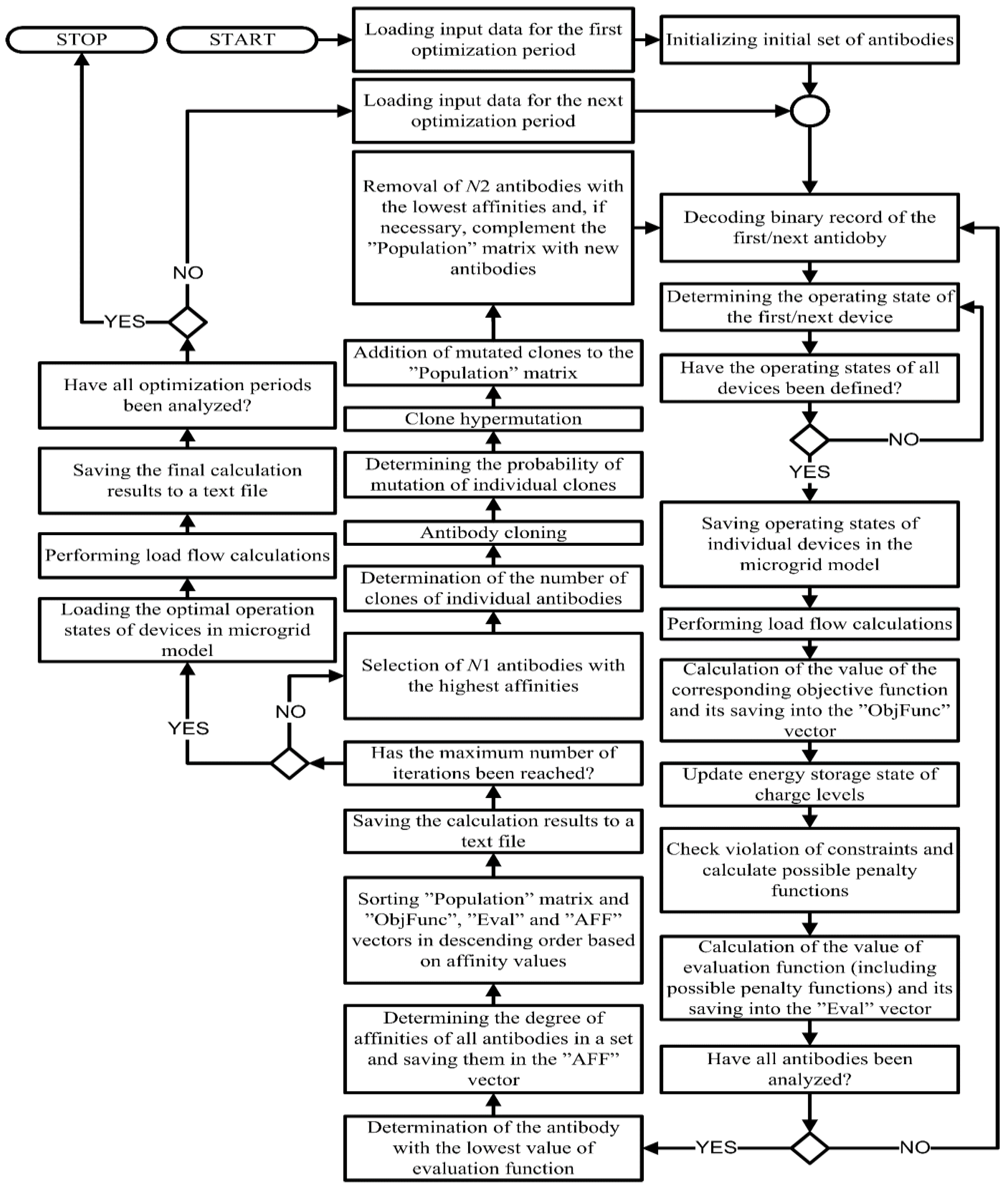
3. Description of the Proposed Microgrid Optimization Algorithm
- the method of representation of the optimization task solutions,
- how to create the initial set of antibodies (candidate solutions),
- the method of assessing the solution (formulation of the evaluation function),
- how to adapt the AIS during its operation.
4. Case Study
4.1. Description of Test Hybrid Microgrid
- from 5% to 95% of the storage capacity between 12:00 am to 6:50 pm,
- from 40% to 60% of the storage capacity between 7:00 pm to 11:50 pm.
4.2. Results of Optimization Calculations Carried out Using the Modified CLONALG Algorithm
- number of antibodies: ,
- number of antibodies selected for cloning: ,
- number of antibodies replaced by randomly generated new antibodies: ,
- maximum probability of mutation: ,
- minimum probability of mutation: ,
- maximum number of clones created for single antibody: ,
- minimum number of clones created for single antibody: .
4.3. Comparison of Calculation Results Obtained Using the CLONALG Algorithm and the Evolutionary Algorithm
- all defined optimization tasks,
- synchronous and island operation of the test microgrid,
- total achievable RES active power generation capacity equal to 75.225 kW,
- total load demand for active power equal to 10.704 kW.
4.4. Discussion
- cloning probability directly proportional to the affinity of the antibody to antigen, combined with inverse proportional hypermutation,
- removal from the population antibodies with the lowest affinity to antigen.
5. Conclusions
- It is possible to use an AIS based on the CLONALG algorithm as an effective optimization tool for hybrid AC/DC microgrids operating on both synchronous and island mode,
- in most of the considered cases, optimization with the use of an AIS resulted in finding a better solution compared to optimization with an evolutionary algorithm,
- the introduced modification of the hypermutation operator contributed to the improvement of the obtained results in relation to the classic version of CLONALG algorithm as well as evolutionary algorithm,
- the modified CLONALG algorithm showed a stronger tendency to reject suboptimal solutions in the early phase of the optimization process than its classic version,
- the artificial immune system, operating on the basis of the CLONALG algorithm, requires greater computational effort that the commonly used evolutionary algorithm; however, the aforementioned tendency to quickly reject suboptimal solutions at an early stage of the optimization process may be an advantage of the AIS,
- both algorithms, due to the way they work, do not guarantee that the solution they find is a global optimum. The analysis of the convergence of these algorithms suggest that the obtained solutions are a quite good approximation of the global optimum.
- the optimization tasks formulated and solved in this paper can be implemented in real installations. However, this process requires the construction of an appropriate telecommunications infrastructure that allows monitoring the state of individual microgrid elements and sending control signals to them.
Funding
Institutional Review Board Statement
Informed Consent Statement
Data Availability Statement
Conflicts of Interest
Abbreviations
| EA | Evolutionary algorithm |
| PSO | Particle swarm optimization |
| AIS | Artificial immune systems |
| AC | Alternating current |
| DC | Direct current |
| CLONALG | Clonal selection algorithm |
| RES | Renewable energy sources |
| ESD | Energy storage device |
| EPC | Electronic power converter |
| V2G | Vehicle to grid |
| MV | Medium voltage |
| LV | Low voltage |
| SOC | State of charge |
| HMO | Hybrid microgrid operator |
| DSO | Distribution system operator |
| RE | Reciprocating engine |
| MPP | Maximum power operation point |
Nomenclature:
| total active power losses in the hybrid microgrid during the optimization period | |
| // | number of power lines/transformers/EPCs in the hybrid microgrid |
| // | active power losses in the power line/ transformer/ EPC belonging to the hybrid microgrid |
| total costs related to the operation of hybrid microgrid during the optimization period | |
| / | total fixed/variable costs related to the operation of hybrid microgrid during the optimization period |
| fixed costs related to maintaining the connection of hybrid microgrid with external distribution system | |
| / | fixed costs related to the maintenance of microsources/ESDs owned by HMO |
| fixed costs related to maintaining the infrastructure enabling consumers to connect microsources and ESDs to the microgrid | |
| variable costs associated with the purchase of energy from DSO | |
| / | variable costs related to the operation of microsources/ESDs owned by HMO |
| / | variable costs related to the purchase of energy generated in microsources/taken from energy storage units owned by individual customers supplied from hybrid microgrid |
| total active power generated in RES belonging to hybrid microgrid during the optimization period | |
| number of RES installed in hybrid microgrid | |
| active power generated by RES | |
| vector which coding a candidate solution | |
| objective function for optimization task | |
| / | apparent/active power generated by microsource connected to the AC/DC part of hybrid microgrid |
| / | nominal apparent/active power of the microsource connected to the AC/DC part of hybrid microgrid |
| / | set of microsources connected to the AC/DC part of hybrid microgrid |
| / | apparent/active power measured at the connection point of ESD connected to AC/DC part of hybrid microgrid |
| / | nominal apparent/active power of the ESD connected to AC/DC part of hybrid microgrid |
| / | set of ESDs connected to AC/DC part of hybrid microgrid |
| // | power factor of the microsource/ESD/EPC connected to the AC part of hybrid microgrid |
| // | nominal power factor of the microsource/ESD/EPC connected to the AC part of hybrid microgrid |
| // | set of microsources/ESDs/EPCs connected to the AC part of hybrid microgrid |
| current flow in the power line | |
| long-term current capacity of the power line | |
| set of power lines belonging to the hybrid microgrid | |
| / | minimum/maximum allowable voltage level for node |
| voltage measured in node | |
| set of nodes belonging to the hybrid microgrid | |
| / | apparent/active power flow through the alternating/direct current circuits of the EPC |
| / | nominal apparent/active power of the EPC |
| apparent power flow through the transformer | |
| nominal apparent power of transformer | |
| / | set of EPCs/transformers belonging to the hybrid microgrid |
| / | minimum/maximum allowable SOC level of the ESD |
| current SOC level of the ESD | |
| set of ESDs belonging to the hybrid microgrid | |
| active power generated by a synchronous generator acting as a balancing source | |
| evaluation function for optimization task | |
| non-negative constant for task 3 | |
| evaluation function after taking into account the penalty functions | |
| evaluation function for optimization task | |
| number of defined constraints | |
| general form of the penalty function for constraint | |
| detailed form of the penalty function for constraint | |
| / | non-negative coefficient of sensitivity of the penalty function significant for minor/major exceedances of constraint |
| affinity of antibody | |
| value of the evaluation function of the antibody encoding the best solution found so far | |
| number of clones of antibody from selected antibodies | |
| / | maximum/minimum number of clones created for a single antibody |
| / | maximum / minimum affinity of selected antibodies |
| constant value | |
| probability of mutation of antibody among the clones created | |
| / | minimum/maximum probability of mutation |
References
- Askarzadeh, A. A memory-based genetic algorithm for optimization of power generation in a microgrid. IEEE Trans. Sustain. Energy 2018, 9, 1081–1089. [Google Scholar] [CrossRef]
- Rana, M.J.; Zaman, F.; Ray, T.; Sarker, R. Economic-environmental scheduling of community microgrid using evolutionary algorithm. In Proceedings of the 2020 IEEE Symposium series on computational intelligence (SSCI), Canberra, Australia, 1–4 December 2020. [Google Scholar] [CrossRef]
- Xu, Y.Q.; Sun, K.Y. Economic optimization of a community-scale integrated energy microgrid based on PSO algorithm. In Proceedings of the 2020 12th IEEE PES Asia-Pacific and Energy Engineering Conference (APPEEC), Nanjing, China, 20–23 September 2020. [Google Scholar] [CrossRef]
- Radosavljević, J.; Jevtić, M.; Klimenta, D. Energy and operation management of a microgrid using particle swarm optimization. Eng. Optim. 2016, 48, 811–830. [Google Scholar] [CrossRef]
- De Castro, L.N.; Timmis, J.I. Artificial immune systems as a novel soft computing paradigm. Soft Comput. 2003, 7, 526–544. [Google Scholar] [CrossRef]
- Lee, T.F.; Hsiao, Y.C.; Wu, H.Y.; Huang, T.L.; Fang, F.M.; Cho, M.Y. Optimization of reactive power compensation and voltage regulation using artificial immune algorithm for radial transmission networks. In Proceedings of the 2007 International Conference on Intelligent Systems Application to Power Systems, ISAP, Toki Messe, Niigata, Japan, 5–8 November 2007. [Google Scholar] [CrossRef]
- Pattanaik, J.K.; Basu, M.; Dash, D.P. Optimal Power flow with FACTS devices Rusing artificial immune systems. In Proceedings of the 2017 International Conference on Technological Advancements in Power and Energy, TAP Energy, Kollam, India, 21–23 December 2017. [Google Scholar] [CrossRef]
- Gárate, J.I.; Ibarra, E.; Martinez de Alegria, I.; Planas, E.; Andreu, J. AC and DC technology in microgrids: A review. Renew. Sustain. Energy Rev. 2014, 43, 726–749. [Google Scholar]
- Hybrid AC/DC Microgrids: A Bridge to Future Energy Distribution System. Available online: http://www.acs.eonerc.rwth-aachen.de/cms/E-ON-ERC-ACS/Forschung/Abgeschlossene-Projekte/~euwe/HYBRID-AC-DC-MICROGRIDS-A-BRIDGE-TO-FUT/?lidx=1 (accessed on 15 May 2019).
- Liu, X.; Wang, P.; Loh, P.C. A hybrid AC/DC micro-grid. In Proceedings of the 2010 9th International Power and Energy Conference, IPEC 2010, Singapore, 27–29 October 2010. [Google Scholar] [CrossRef]
- Xiao, J.; Nguyen, X.B.; Wang, P.; Huang, J.; Zhou, Q. Implementation of DC/DC converter with high frequency transformer (DHFT) in hybrid AC/DC microgrid. In Proceedings of the 2017 Asian Conference on Energy, Power and Transportation Electrification, ACEPT, Singapore, 24–26 October 2017. [Google Scholar] [CrossRef]
- Bandla, K.C.; Prasad Padhy, N. A Multilevel Dual Converter Fed Open End Transformer Configuration for Hybrid AC-DC Microgrid. In Proceedings of the IEEE Power and Energy Society General Meeting, Portland, OR, USA, 5–10 August 2018. [Google Scholar] [CrossRef]
- Gu, L.; Jin, K.; Zhu, H.; Wang, C. A single-stage isolated three-phase bidirectional AC/DC converter. In Proceedings of the 2014 IEEE 5th International Symposium on Power Electronics for Distributed Generation Systems, PEDG, Galway, Ireland, 24–27 June 2014. [Google Scholar] [CrossRef]
- Lachichi, A.; Junyent-Ferre, A.; Green, T. Power converters design for hybrid LV ac/dc microgrids. In Proceedings of the 2017 6th International Conference on Renewable Energy Research and Applications, ICRERA, San Diego, CA, USA, 5–8 November 2017. [Google Scholar] [CrossRef]
- Wu, X.; Wang, Z.; Ding, T.; Li, Z. Hybrid AC/DC Microgrid Planning with Optimal Placement of DC Feeders. Energies 2019, 12, 1751. [Google Scholar] [CrossRef] [Green Version]
- Li, J.; Cai, H.; Yang, P.; Wei, W. A Bus-Sectionalized Hybrid AC/DC Microgrid: Concept, Control Paradigm, and Implementation. Energies 2021, 14, 3508. [Google Scholar] [CrossRef]
- Nasir, M.; Khan, H.A. Solar photovoltaic integrated building scale hybrid AC/DC microgrid. In Proceedings of the 5th IET International Conference on Renewable Power Generation (RPG), London, UK, 21–23 September 2016. [Google Scholar] [CrossRef]
- Ma, T.; Cintuglu, M.H.; Mohammed, O. Control of hybrid AC/DC microgrid involving energy storage, renewable energy and pulsem loads. In Proceedings of the 2015 IEEE Industry Applications Society Annual Meeting IAS 2015, Addison, OR, USA, 18–22 October 2015. [Google Scholar] [CrossRef]
- Vigneysh, T.; Kumarappan, N.; Arulraj, R. Operation and control of wind/fuel cell based hybrid microgrid in grid connected mode. In Proceedings of the 2013 IEEE International Multi-Conference on Automation, Computing, Control, Communication and Compressed Sensing, (iMac4s), Kattayam, India, 22–23 March 2013. [Google Scholar] [CrossRef]
- Debela, T.; Bhattacharya, A. Design and analysis of a DC/AC microgrid with centralized battery energy storage system. In Proceedings of the IECON 2017—43rd Annual Conference of the IEEE Industrial Electronics Society, Beijing, China, 29 October–1 November 2017. [Google Scholar] [CrossRef]
- Rahman, M.S.; Hossain, M.J.; Lu, J. Utilization of parked EV-ESS for power management in a grid-tied hybrid AC/DC microgrid. In Proceedings of the Ausralasian Universities Power Engineering Conference, AUPEC 2015, Wollongong, Australia, 27–30 September 2015. [Google Scholar] [CrossRef] [Green Version]
- Rahman, M.S.; Hossain, M.J.; Rafi FH, M.; Lu, J. EV charging in a commercial hybrid AC/DC microgrid: Configuration, control and impact analysis. In Proceedings of the 2016 Australasian Universities Power Engineering Conference, AUPEC 2016, Brisbane, Australia, 25–28 September 2016. [Google Scholar] [CrossRef] [Green Version]
- Ouramdane, O.; Elbouchikhi, E.; Amirat, Y.; Sedgh Gooya, E. Optimal Sizing and Energy Management of Microgrids with Vehicle-to-Grid Technology: A Critical Review and Future Trends. Energies 2021, 14, 4166. [Google Scholar] [CrossRef]
- Kaushik, R.A.; Pindoriya, N.M. A hybrid AC-DC microgrid: Opportunities & key issues in implementation. In Proceedings of the IEEE International Conference on Green Computing, Communication and Electrical Engineering, ICGCCEE 2014, Coimbatore, India, 6–8 March 2014. [Google Scholar] [CrossRef]
- Unamuno, E.; Barrena, J.A. Hybrid ac/dc microgrids—Part I: Review and classification of topologies. Renew. Sustain. Energy Rev. 2015, 52, 1251–1259. [Google Scholar] [CrossRef]
- Mirsaeidi, S.; Dong, X.; Said, D.M. Towards hybrid AC/DC microgrids: Critical analysis and classification of protection strategies. Renew. Sustain. Energy Rev. 2018, 90, 97–103. [Google Scholar] [CrossRef]
- Mirsaeidi, S.; Dong, X.; Shi, S.; Tzelepis, D. Challenges, advances and future directions in protection of hybrid AC/DC microgrids. IET Renew. Power Gener. 2017, 11, 1495–1502. [Google Scholar] [CrossRef] [Green Version]
- Rahman Fahim, S.; Sarker, S.K.; Muyeen, S.M.; Sheikh, M.R.I.; Das, S.K. Microgrid Fault Detection and Classification: Machine Learning Based Approach, Comparison, and Reviews. Energies 2020, 13, 3460. [Google Scholar] [CrossRef]
- Ambia, M.N.; Al-Durra, A.; Muyeen, S.M. Centralized power control strategy for AC-DC hybrid micro-grid system using multi-converter scheme. In Proceedings of the IECON 2011—37th Annual Conference of the IEEE Industrial Electronics Society, Melbourne, Australia, 7–10 November 2011. [Google Scholar] [CrossRef] [Green Version]
- Aryani, D.R.; Song, H. Coordination Control Strategy for AC/DC Hybrid Microgrids in Stand-Alone Mode. Energies 2016, 9, 469. [Google Scholar] [CrossRef]
- PowerFactory v.15.2 Manual (DIgSILENT Technical Documentation). Available online: http://www.digsilent.de (accessed on 13 September 2019).
- Hoke, A.; Maksimović, D. Active power control of photovoltaic power systems. In Proceedings of the 2013 1st IEEE Conference on Technologies for Sustainability, SusTech, Portland, OR, USA, 1–2 August 2013. [Google Scholar] [CrossRef]
- Khosa, F.K.; Zia, M.F.; Bhatti, A.A. Genetic algorithm based optimization of economic load dispatch constrained by stochastic wind power. In Proceedings of the ICOSST 2015 International Conference on Open Source Systems and Technologies, Lahore, Pakistan, 17–19 December 2015. [Google Scholar] [CrossRef]
- Naimi, D.; Ahmed, S.; Bouktir, T. An efficient optimization method based on genetic algorithm applied to reduce greenhouse gases in power system. In Proceedings of the 2013 International Conference on Control, Decision and Information Technologies, CoDIT, Hammamet, Tunisia, 6–8 May 2013. [Google Scholar] [CrossRef]
- Babaei, A.; Razavi, S.; Kamali, S.; Gholami, A. Performance improvement of power system stabilizer be genetic algorithm for one machine infinite bus system. In Proceedings of the 2007 42nd International Universities Power Engineering Conference, Brighton, UK, 4–6 September 2007. [Google Scholar] [CrossRef]
- Liang, H.; Gu, X.; Zhao, D. Optimization of system partitioning schemes for power system black-start restoration based on genetic algorithms. In Proceedings of the 2010 Asia-Pacific Power and Energy Engineering Conference, APPEEC, Chengdu, China, 28–31 March 2010. [Google Scholar] [CrossRef]
- Atia, R.; Yamada, N. Optimization of a PV-wind-diesel system using a hybrid genetic algorithm. In Proceedings of the 2012 IEEE Electrical Power and Energy Conference, London, ON, Canada, 10–12 October 2012. [Google Scholar] [CrossRef]


| EPC | ||||||
| 125 | 0.4 | 0.4 | 0.8 | 5 | 0.5 | |
| MV/LV Transformer | ||||||
| 63 | 15.75 | 0.4 | 4.5 | 1.2 | 0.18 | |
| AC line AsXS 4 × 70 | ||||||
| 0.443 | 0.083 | 213 | ||||
| MV line AFL6 35 | ||||||
| 0.852 | 0.4 | 145 | ||||
| DC line AsXS 2 × 70 | ||||||
| 0.443 | 213 | |||||
| Microsource | Owner | Nominal Power [kW]/[kVA] * | [kW] | [kW] | [kvar] | [kvar] |
|---|---|---|---|---|---|---|
| AP | HMO | 61 | 0 | 49 | −36.7 | 36.7 |
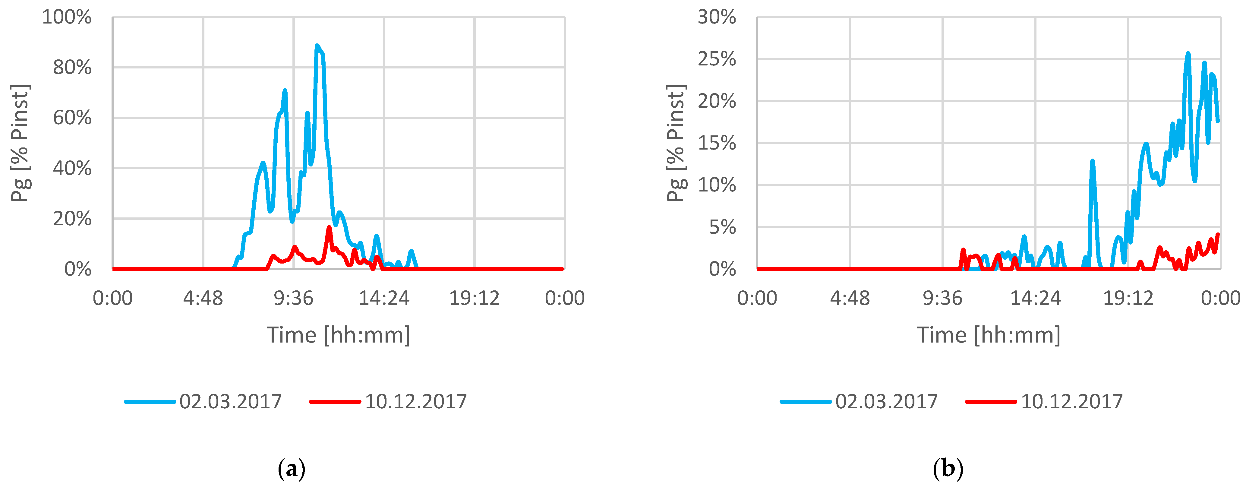
| PV | HMO | 40 | 0 | It depends on the atmospheric conditions prevailing in a given optimization period | 0 | 0 |
| PV12 | Consumer | 4 | 0 | 0 | 0 | |
| PV16 | Consumer | 25 | 0 | 0 | 0 | |
| PV23 | Consumer | 6 | 0 | 0 | 0 | |
| PV24 | Consumer | 10 | 0 | 0 | 0 | |
| TW14 | Consumer | 2 | 0 | 0 | 0 | |
| TW22 | Consumer | 5 | 0 | 0 | 0 | |
| TW26 | Consumer | 3 | 0 | 0 | 0 |
| Optimization Task | Synchronous Operation | Island Operation |
|---|---|---|
| Task 1 | 200 | 200 |
| Task 2 | 200 | 450 |
| Task 3 | 150 | 250 |
| Test Microgrid Operation Mode | Time | RES Generation Profiles Date | Day Type | Optimized Quality Indicator | Other Quality Indicators | |
|---|---|---|---|---|---|---|
| Active Power Losses [kW] | Costs [USD] | Level of Power Generated in RES [kW] | ||||
| Synchronous | 10:50 am | 2 March 2017 | working day | 1.086 | 3.565 | 35.550 |
| Holiday | 0.839 | 3.766 | 15.468 | |||
| 10 December 2017 | working day | 1.081 | 2.977 | 0.754 | ||
| holiday | 1.421 | 2.958 | 1.147 | |||
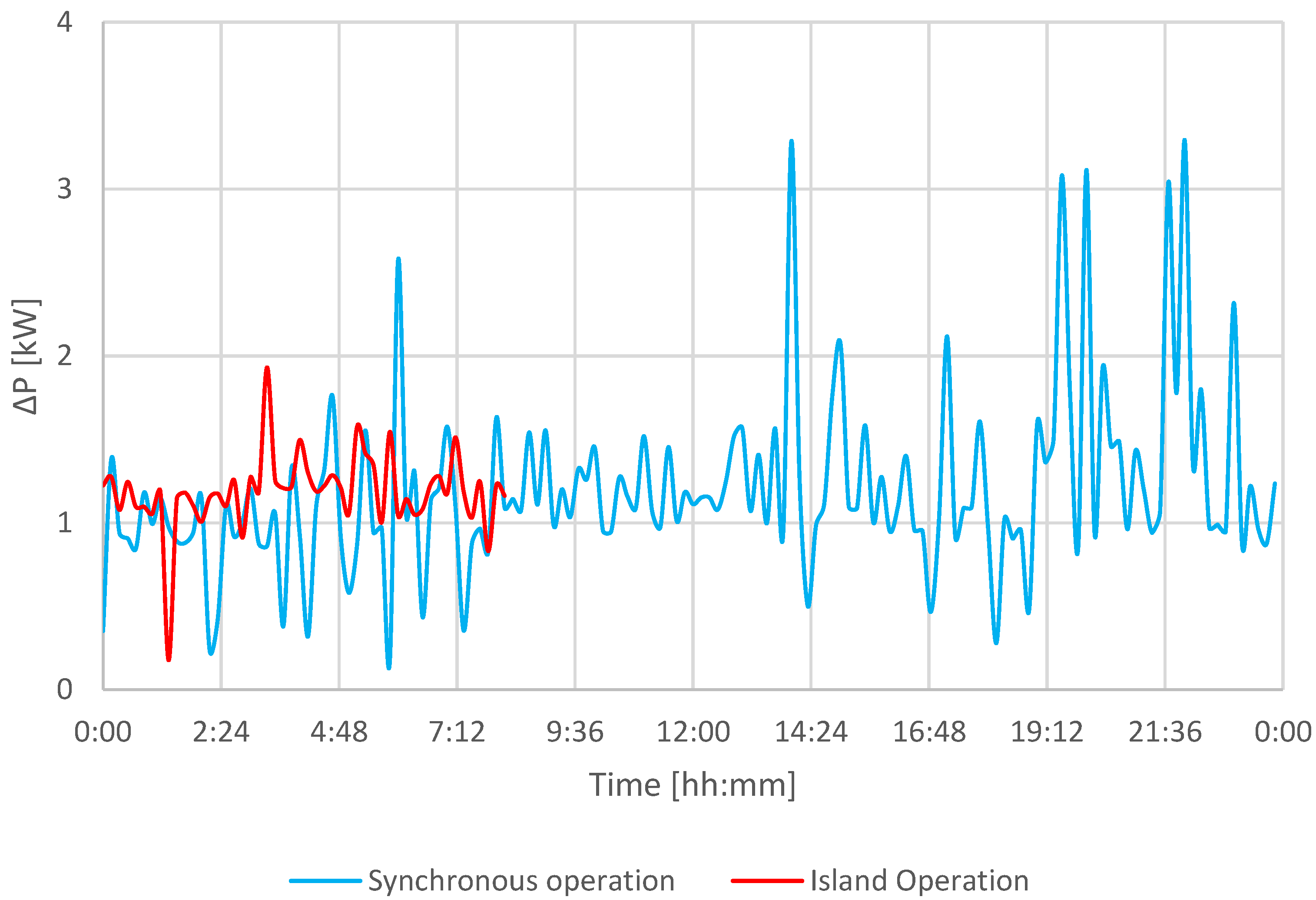
| Island | 5:30 am | 2 March 2017 | working day | 1.346 | 3.338 | 0.000 |
| holiday | 1.161 | 3.578 | 0.000 | |||
| 10 December 2017 | working day | 1.293 | 3.204 | 0.000 | ||
| holiday | 1.670 | 3.454 | 0.000 | |||
| Test Microgrid Operation Mode | Time | RES Generation Profiles Date | Day Type | Optimized Quality Indicator | Other Quality Indicators | |
|---|---|---|---|---|---|---|
| Costs [USD] | Active Power Losses [kW] | Level of Power Generated in RES [kW] | ||||
| Synchronous | 10:50 am | 2 March 2017 | working day | 3.304 | 1.231 | 0.000 |
| holiday | 2.707 | 0.927 | 4.678 | |||
| 10 December 2017 | working day | 3.053 | 2.515 | 0.000 | ||
| holiday | 3.267 | 2.130 | 0.000 | |||
| Island | 5:30 am | 2 March 2017 | working day | 2.601 | 0.886 | 0.000 |
| holiday | 2.657 | 0.956 | 0.000 | |||
| 10 December 2017 | working day | 3.094 | 1.235 | 0.000 | ||
| holiday | 2.657 | 0.956 | 0.000 | |||
| Test Microgrid Operation Mode | Time | RES Generation Profiles Date | Day Type | Optimized Quality Indicator | Other Quality Indicators | |
|---|---|---|---|---|---|---|
| Level of Power Generated in RES [kW] | Costs [USD] | Active Power Losses [kW] | ||||
| Synchronous | 10:50 am | 2 March 2017 | working day | 29.576 | 4.681 | 3.774 |
| holiday | 62.094 | 5.230 | 3.148 | |||
| 10 December 2017 | working day | 1.702 | 3.586 | 1.495 | ||
| holiday | 1.696 | 4.525 | 3.039 | |||
| Island | 5:30 am | 2 March 2017 | working day | 0.000 | 3.602 | 1.499 |
| holiday | 0.000 | 3.602 | 1.499 | |||
| 10 December 2017 | working day | 0.000 | 3.602 | 1.499 | ||
| holiday | 0.000 | 3.602 | 1.499 | |||
| Optimization Task | RES Generation Capacity Profile | Power Demand Profile | Percentage of Optimization Periods at Which: | Number of Analyzed Optimization Periods | ||
|---|---|---|---|---|---|---|
| CLONALG Algorithm Achieved a Better Solution | Evolutionary Algorithm Achieved a Better Solution | Both Algorithms Reached an Identical Solution | ||||
| Task 1 | 2 March 2017 | working day | 83.33% | 16.67% | 0.00% | 144 |
| holiday | 79.86% | 20.14% | 0.00% | 144 | ||
| 10 December 2017 | working day | 86.81% | 13.19% | 0.00% | 144 | |
| holiday | 79.86% | 20.14% | 0.00% | 144 | ||
| Task 2 | 2 March 2017 | working day | 91.67% | 8.33% | 0.00% | 144 |
| holiday | 91.67% | 8.33% | 0.00% | 144 | ||
| 10 December 2017 | working day | 92.36% | 7.64% | 0.00% | 144 | |
| holiday | 86.11% | 13.89% | 0.00% | 144 | ||
| Task 3 | 2 March 2017 | working day | 61.81% | 2.78% | 35.42% | 144 |
| holiday | 61.81% | 2.78% | 35.42% | 144 | ||
| 10 December 2017 | working day | 36.81% | 0.00% | 63.19% | 144 | |
| holiday | 36.81% | 0.00% | 63.19% | 144 | ||
| Optimization Task | RES Generation Capacity Profile | Power Demand Profile | Percentage of Optimization Periods at Which: | Number of Analyzed Optimization Periods | ||
|---|---|---|---|---|---|---|
| CLONALG Algorithm Achieved a Better Solution | Evolutionary Algorithm Achieved a Better Solution | Both Algorithms Reached an Identical Solution | ||||
| Task 1 | 2 March 2017 | working day | 90.00% | 10.00% | 0.00% | 50 |
| holiday | 92.16% | 7.84% | 0.00% | 51 | ||
| 10 December 2017 | working day | 93.24% | 6.76% | 0.00% | 74 | |
| holiday | 88.41% | 11.59% | 0.00% | 69 | ||
| Task 2 | 2 March 2017 | working day | 100.00% | 0.00% | 0.00% | 114 |
| holiday | 98.77% | 1.23% | 0.00% | 81 | ||
| 10 December 2017 | working day | 100.00% | 0.00% | 0.00% | 92 | |
| holiday | 98.91% | 1.09% | 0.00% | 92 | ||
| Task 3 | 2 March 2017 | working day | 14.29% | 0.00% | 85.71% | 42 |
| holiday | 11.36% | 0.00% | 88.64% | 44 | ||
| 10 December 2017 | working day | 30.77% | 0.00% | 69.23% | 52 | |
| holiday | 14.00% | 0.00% | 86.00% | 50 | ||
| Test Microgrid Operation Mode | Optimized Quality Indicator | Evolutionary Algorithm | CLONALG Algorithm | |
|---|---|---|---|---|
| With Modified Hypermutation Operator | With Classic Hypermutation Operator | |||
| Synchronous | Active power losses [kW] | 1.220 | 1.291 | 1.254 |
| Costs [USD] | 3.923 | 3.091 | 3.679 | |
| Level of power generated in RES [kW] | 52.082 | 61.478 | 58.369 | |
| Island | Active power losses [kW] | 1.180 | 1.031 | 1.081 |
| Costs [USD] | 3.960 | 2.871 | 3.556 | |
| Level of power generated in RES [kW] | 55.774 | 61.957 | 57.875 | |
Publisher’s Note: MDPI stays neutral with regard to jurisdictional claims in published maps and institutional affiliations. |
© 2021 by the author. Licensee MDPI, Basel, Switzerland. This article is an open access article distributed under the terms and conditions of the Creative Commons Attribution (CC BY) license (https://creativecommons.org/licenses/by/4.0/).
Share and Cite
Rokicki, Ł. Optimization of the Configuration and Operating States of Hybrid AC/DC Low Voltage Microgrid Using a Clonal Selection Algorithm with a Modified Hypermutation Operator. Energies 2021, 14, 6351. https://0-doi-org.brum.beds.ac.uk/10.3390/en14196351
Rokicki Ł. Optimization of the Configuration and Operating States of Hybrid AC/DC Low Voltage Microgrid Using a Clonal Selection Algorithm with a Modified Hypermutation Operator. Energies. 2021; 14(19):6351. https://0-doi-org.brum.beds.ac.uk/10.3390/en14196351
Chicago/Turabian StyleRokicki, Łukasz. 2021. "Optimization of the Configuration and Operating States of Hybrid AC/DC Low Voltage Microgrid Using a Clonal Selection Algorithm with a Modified Hypermutation Operator" Energies 14, no. 19: 6351. https://0-doi-org.brum.beds.ac.uk/10.3390/en14196351