
Shaft Voltage Reduction Method Using Carrier Wave Phase Shift in IPMSM


1
Electrical Engineering Department, Incheon National University, Songdo 22012, Korea
2
Korea Electrotechnology Research Institute (KERI), Changwon 51543, Korea
*
Author to whom correspondence should be addressed.
Energies 2021, 14(21), 6924; https://0-doi-org.brum.beds.ac.uk/10.3390/en14216924
Submission received: 6 October 2021
/
Revised: 15 October 2021
/
Accepted: 18 October 2021
/
Published: 21 October 2021
(This article belongs to the Special Issue High Performance Permanent Magnet Synchronous Motor Drives)
Abstract
:Common-Mode Voltage (CMV) induces shaft voltage and bearing current due to the electrical interaction with the parasitic capacitance of the motor. CMV, shaft voltage, and bearing current are considered the major causes of bearing fault. Motor fault in a traction system poses a risk of accidents. Therefore, it is necessary to reduce the CMV and the shaft voltage to ensure the reliability of the bearing. However, some existing CMV reduction methods are based on asynchronized space vector pulse width modulation (SVPWM), which will cause unacceptable harmonic distortion at a low switching frequency. Alternatively, some CMV reduction methods based on synchronized SVPWM burden the processor because they require a lot of calculation. In this paper, the method to reduce CMV and shaft voltage is proposed using carrier wave phase shift in SVPWM. CMV is explained in traditional SVPWM, and CMV is reduced by shifting the carrier wave phase of one phase. The simulation model is constructed through MATLAB/SIMULINK and Maxwell 2D/Twin Builder. Considering the proposed method, CMV, shaft voltage, and bearing current are analyzed by an equivalent circuit model. Moreover, the output torque behaviors with different input currents are analyzed through the simulation.
1. Introduction
The interior permanent magnet synchronous motor (IPMSM) with pulse width modulated (PWM) inverter has been used in a wide range of applications because of its high efficiency, better performance, and ability to control a wide area. It is especially used in traction systems such as electric vehicles, urban air mobilities, and electric ships. In these systems, motor faults can lead to accidents, and accidents can lead to huge damage such as casualties or property damage. That is why the reliability of the motor is very important. Thus, research on motor faults should be carried out for reliability.
There are four main types of faults of IPMSM such as inter-turn faults [1,2], demagnetization [3,4], eccentricity faults [5,6], and bearing faults [7,8]. Among them, bearing faults are the most frequent type of faults in IPMSM. During operation, fatigue cracks occur on the bearing surface until metal pieces fall due to overload. Generalized-roughness defects are those that significantly degrade, rough, or deform the bearing surface. Common causes of this type of fault include contamination, lack or loss of lubricant, and misalignment [9,10,11]. Therefore, studies of bearing faults have received a lot of attention to prevent motor efficiency reduction and increase reliability.
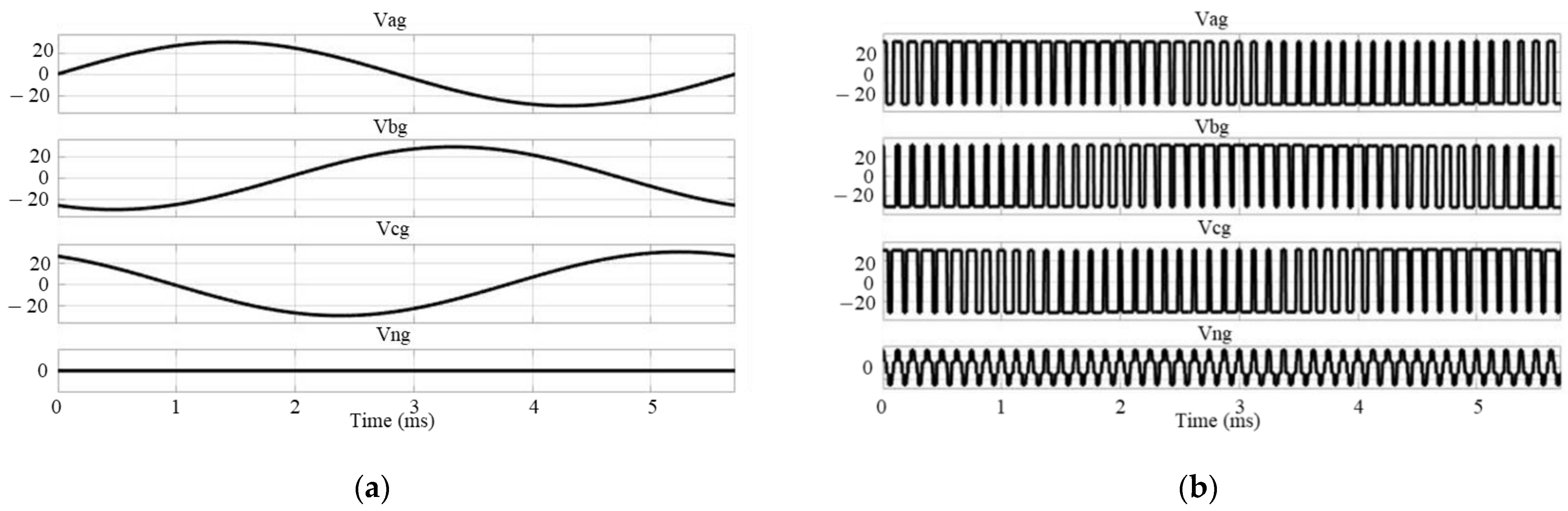
As shown in Figure 1a, common-mode voltage (CMV) does not occur in the ideal three-phase power source. However, in practice, the PWM inverter generates CMV, as shown in Figure 1b. The CMV occurring at this time interacts with the component of the parasitic capacitance of the motor to induce shaft voltage and bearing current. They are noted as important factors in bearing faults [12,13,14]. Therefore, research to reduce CMV, shaft voltage, and bearing current is required to improve the reliability of the bearing system.
In [15], the shaft is directly grounded using a special ring to lower the shaft voltage. In [16], The electromagnetic shielding slot wedge (ESLW) is proved to be an efficient method to attenuate the discharging bearing current in motors fed by PWM inverters. In [17], the electric shield is used to reduce the shaft voltage. Another study [18] reduces the parasitic capacitances using the winding technique. However, most previous studies propose the shaft voltage reduction method by modifying the motor structure. It is necessary to analyze CMV, shaft voltage, and bearing current in a basic three-phase motor driving system without any deformation of the motor.
In [19,20,21,22,23,24,25], numerous PWM strategies are proposed to reduce CMV. In [19], a reduced CMV PWM strategy is designed by employing dual carrier to replace single carrier. The peak value of CMV can be effectively reduced to 1/6 of the DC link voltage. However, there are intervals in which the maximum CMV is half the DC link voltage. Because of the use of sinusoidal PWM (SPWM), the maximum voltage usage is only 78.6%. In [20], a remote state PWM (RSPWM) is presented to reduce CMV by utilizing three odd or even voltage vectors. However, this method can only suppress CMV at a low modulation index. To reduce CMV in a wide range of modulation indexes, some reduced CMV strategies are proposed, including active zero-state PWM (AZSPWM) and near-state PWM (NSPWM) methods [21,22,23]. However, these CMV reduction methods, which are based on asynchronized space vector PWM (SVPWM), will cause unacceptable current distortion including large low-order harmonics and subharmonics. In [24], a modified selective harmonic elimination PWM (M-SHEPWM) for CMV reduction is proposed, which can effectively suppress the CMV by eliminating the lower order harmonics of the output line-line voltage. However, the complicated arithmetic calculations of phase angle greatly increase the computational burden of processors. The reduced common-mode voltage model preemptive control (RCMV-MPC) methods are used to reduce CMV [25]. However, the cost function is calculated at every sampling period, increasing the computational burden on the processor and it is parameter sensitive.
This paper presents a method for reducing CMV and shaft voltage through a carrier wave phase shift (CPS) in IPMSM using SVPWM. First, the switch state and CMV are analyzed in SVPWM. It removes the zero-voltage state using only CPS in the traditional SVPWM. Comparisons of changes in the shaft voltage and bearing current due to CMV changed through simulation are included. Comparisons of input current and output torque in the proposed method are also included. Finally, validation through experiments is shown.
2. CMV and Switching States
The CMV of a three-phase inverter is generally defined as the electric potential difference between the neutral point of inverter output and reference ground:
where is the common-mode voltage. , , and are the input voltages in the three-phase motor, respectively. Table 1 show the CMV according to the switch state in the SVPWM of the three-phase inverter. As shown in Table 1, CMV has a maximum at and which are zero-voltage states. Figure 2 shows the space vector application process in SVPWM, where , and are the duration of , and . is the switching cycle. , and refer to the switch state of each phase. The expression for the , and is:
where and is the angle of and , is the angle of the reference vector, and is the modulation index in SVPWM.
CMV has the maximum value in the zero-voltage vector state, and the zero-voltage state vector should be avoided as much as possible. As shown in Equation (2), is affected by , , and . is a constant that does not change once the system is determined. In PMSM, changes according to the back EMF of the motor. Therefore, changes according to and should be considered. Figure 3 shows the according to modulation index and rotor angle when is normalized to 1. As shown in Figure 3, it can be seen that the larger the , the shorter the duration of the CMV peak value, and the smaller the , the longer the duration of the CMV peak value. It can be seen that as the back EMF of the motor increases, the duration of the CMV peak value becomes longer.
3. Carrier Wave Phase Shift in SVPWM
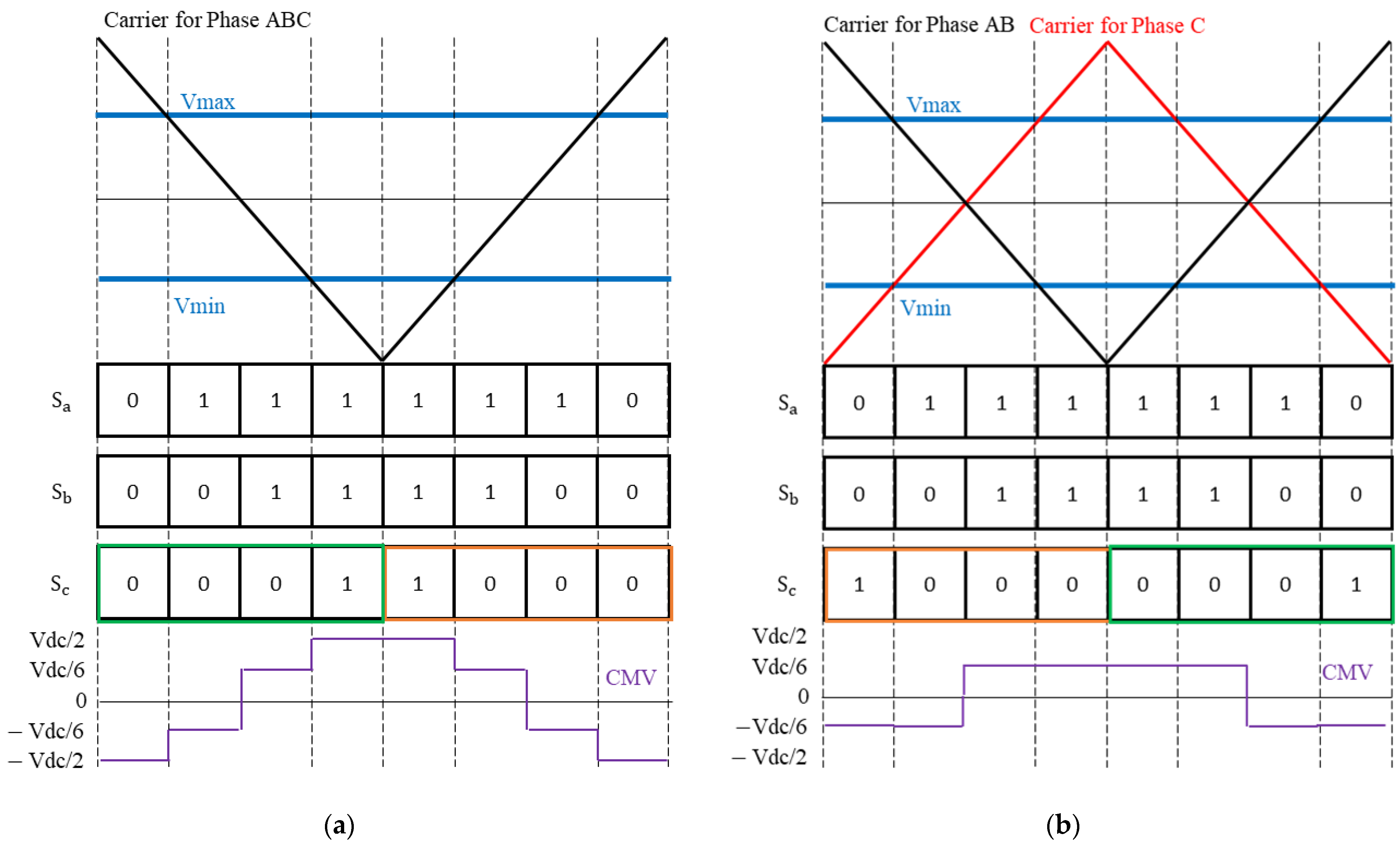
Figure 4 shows the switching state and CMV in traditional SVPWM as well as in the proposed methods. The peak-to-peak value of CMV can be reduced by removing the zero-voltage state from the traditional SVPWM. Previous studies changed the SVPWM method to reduce the zero-voltage state [19,20,21,22,23,24,25]. As a result, the input voltage was distorted, and the output of the motor was affected. CPS has no change in input reference voltage and has the same phase voltage. As shown in Figure 4b, if the carrier of one phase has the opposite phase, the zero-voltage state disappears in all states. In that case, the phase of the voltage on phase C is slightly different. However, the same effect can be obtained by shifting the phase of the carrier wave by 180 degrees unless the input reference voltage of the SVPWM is changed.
4. Equivalent Circuit Model
A shaft voltage equivalent circuit model is constructed to confirm the change in the shaft voltage for the change in CMV. The circuit model schema in the motor driving system is shown in Figure 5. The inverter, which uses the PWM control method, supplies power through the winding of the motor and simultaneously generates CMV. The generated CMV interacts with parasitic capacitance components caused by the motor’s winding, stator, rotor, and bearing, resulting in shaft voltage and bearing current. The shaft voltage is the voltage between the shaft and the frame. The bearing current is the current between the bearing and the shaft.
The structure of the motor with the parasitic capacitance of the motor is shown in Figure 5. Parasitic capacitance is classified into four main types: is the parasitic capacitance between the winding and the stator; is the parasitic capacitance between the winding and the rotor; is the parasitic capacitance between the stator and the rotor; and is the parasitic capacitance between the bearing and the shaft [26].
The simulation equivalent model for comparing the shaft voltage and bearing current is shown in Figure 6. It is assumed that the parasitic capacitance of the winding is affected in the middle of the winding. Therefore, La1 and La2 are the same phase winding, and so are other windings. In this paper, SVPWM is used, but other PWM methods can also be applied. This paper constructed the simulation using the parasitic capacitance equations of motor derived from previous studies [19,26,27].
5. Simulation Results
The parameters of the motor and inverter used in the simulation are shown in Table 2. The control method is used current control at a constant speed to compare CMV, shift voltage, and bearing current. Depending on the PWM modulation index, the duration of each space vector varies. Since the modulation index of the input reference voltage in the IPMSM depends on the magnitude of the back EMF, it is performed at various speeds. A comparison of CMV, shaft voltage, and bearing current at each speed is included. Finally, the changes of the output torque and the THD of the input current are checked.
- A.
- Shaft Voltage and Bearing Current
Figure 8 shows the simulation results of CMV, shift voltage, and bearing current at 500 rpm and 3500 rpm in the traditional SVPWM. Figure 9 shows the simulation results of CMV, shift voltage, and bearing current at 500 rpm and 3500 rpm in the proposed method. Table 3 shows the experimental result values above. It can be seen that 500 rpm has a low modulation index, a long duration of zero voltage state, a high modulation index of 3500 rpm, and a short time of zero voltage state. In the proposed method, it is confirmed that the maximum CMV is reduced to 1/6 Vdc. In the traditional SVPWM, the duration of the maximum of CMV at low speed is long, but in the proposed method, it is same at high speed. In the traditional method, the RMS of CMV is large at low speed with a low modulation index. However, the proposed method has the same RMS value. Similar to the results of CMV, the shaft voltage also decreases. Compared to the conventional SVPWM, the bearing current of the proposed method is small in both the low-speed and high-speed regions in the proposed method
- B.
- Changes of input and output
Figure 9 shows the input current and its FFT waveform through co-simulation for the traditional SVPWM and the proposed method, respectively. In the proposed method, the high order harmonics of the current increase compared to the traditional method. The low order harmonic is almost similar. The THD of the input current increases little in the proposed method. Figure 10 shows the comparison result of the output torque of the co-simulation. Although the torque ripple is increased, the average torque is similar.
6. Experiment Results
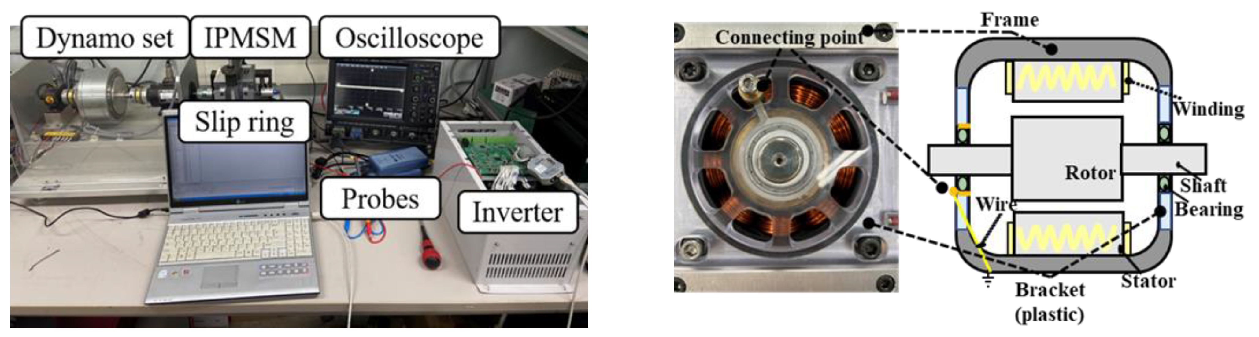
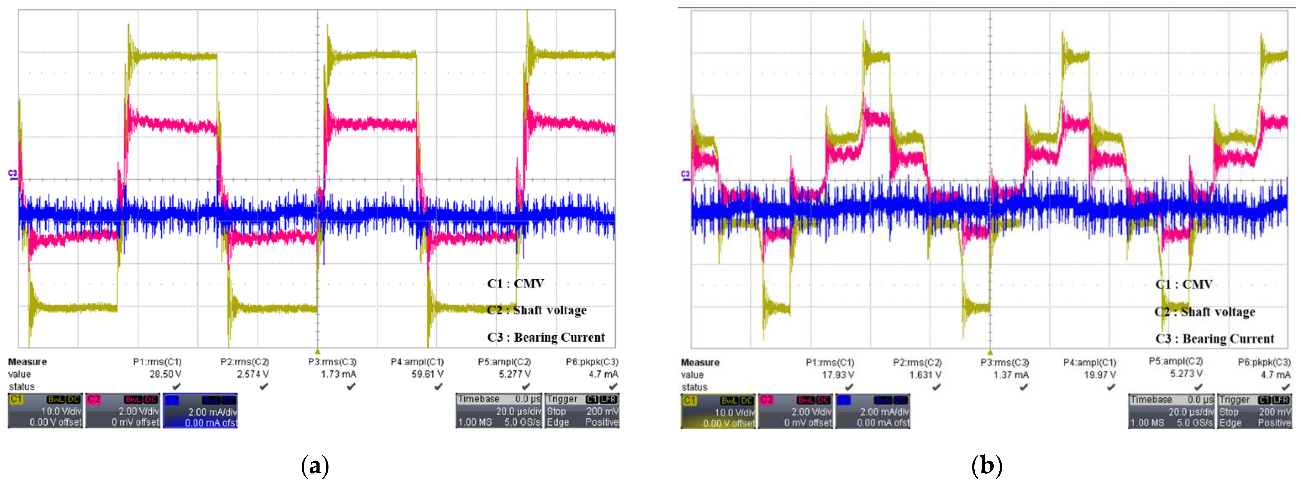
Figure 11 shows the experimental setup used for verification. The motor shown in Table 2 is used. The frame of the motor and the inverter are grounded, and the CMV is measured by connecting the neutral point and ground of the motor. The slip ring is installed on the shaft to measure the shaft voltage. Furthermore, the connection point is made on the outer race of the bearing, as shown in Figure 11. The bracket is made of plastic and the bearings are electrically insulated from the frame. A wire is connected between the connection point and the motor frame. The bearing current is determined by measuring the current in the wire using a current probe. However, it is impossible to accurately measure bearing current because it is different from the real bearing. Therefore, the comparison of the bearing current is relative to the peak-to-peak magnitude.
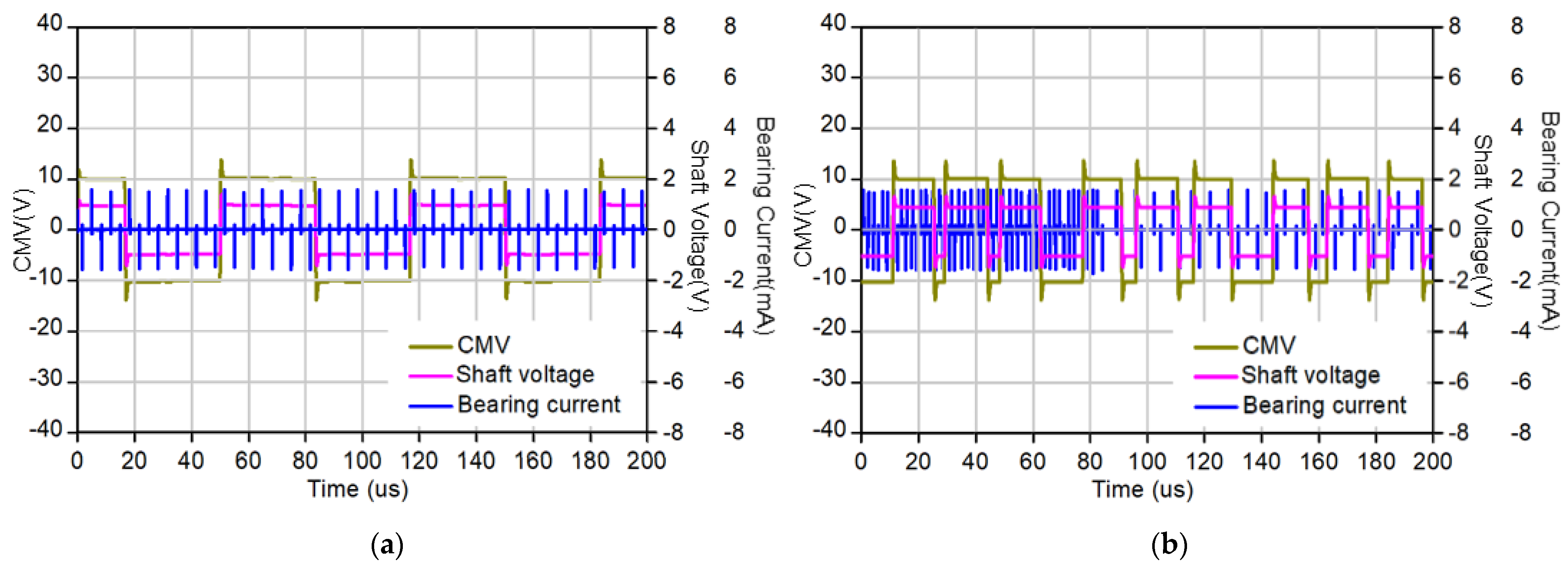
Figure 12 shows the experimental results of CMV, shaft voltage, and bearing current in the traditional SVPWM. Figure 13 shows the experimental results of CMV, shaft voltage and bearing current in the proposed method. The proposed method reduced the peak-to-peak value of CMV by 1/3. As a result, the shaft voltage is also reduced, and the peak-to-peak bearing current is reduced. Additionally, in the proposed method, it is confirmed that the RMS values of the CMV and the shaft voltage do not change according to the speed.
7. Conclusions
In this paper, a CMV and shaft voltage reduction method through carrier wave phase shift in traditional SVPWM is proposed. This is done by configuring CMV and shaft voltage simulation through MATLAB/SIMULINK. CMV, shaft voltage, and bearing current are checked in the proposed method. Through the co-simulation of ANSYS MAXWELL 2D and Twin Builder, the output torque behaviors with changes in input current are confirmed in the proposed method. Finally, experimental results for verification are included. Both the simulation and experimental results are provided to verify the performance of the proposed method. The proposed method reduces CMV and shaft voltage by 1/3. The THD of the input current and the output torque ripple show little increase.
Author Contributions
Methodology, simulation, and writing—original draft preparation by J.-H.I.; conceptualization, writing—review and editing by Y.-K.L. project administration by J.-K.P.; funding acquisition, review, and formal analysis by J.H. All authors have read and agreed to the published version of the manuscript.
Funding
This work was supported by Industrial Strategic Technology Development Program of Korea Evaluation Institute of Industrial Technology (KEIT) (No. 20010132, 20011437).
Institutional Review Board Statement
Not applicable.
Informed Consent Statement
Not applicable.
Data Availability Statement
Not applicable.
Conflicts of Interest
The authors declare no conflict of interest.
References
- Park, J.-K.; Jeong, C.-L.; Lee, S.-T.; Hur, J. Early detection technique for stator winding inter-turn fault in bldc motor using input impedance. IEEE Trans. Ind. Appl. 2014, 51, 240–247. [Google Scholar] [CrossRef]
- Park, J.-K.; Hur, J. Detection of Inter-Turn and dynamic eccentricity faults using stator current frequency pattern in IPM-Type BLDC Motors. IEEE Trans. Ind. Electron. 2015, 63, 1771–1780. [Google Scholar] [CrossRef]
- Hong, J.; Park, S.; Hyun, D.; Kang, T.-J.; Bin Lee, S.; Kral, C.; Haumer, A. Detection and classification of rotor demagnetization and eccentricity faults for pm synchronous motors. IEEE Trans. Ind. Appl. 2012, 48, 923–932. [Google Scholar] [CrossRef]
- Ebrahimi, B.M.; Faiz, J. Demagnetization Fault diagnosis in surface mounted permanent magnet synchronous motors. IEEE Trans. Magn. 2013, 49, 1185–1192. [Google Scholar] [CrossRef]
- Esfahani, E.; Wang, S.; Sundararajan, V. Multisensor wireless system for eccentricity and bearing fault detection in induction motors. IEEE ASME Trans. Mechatron. 2014, 19, 818–826. [Google Scholar] [CrossRef]
- Ebrahimi, B.M.; Roshtkhari, M.J.; Faiz, J.; Khatami, S.V. Advanced eccentricity fault recognition in permanent magnet synchronous motors using stator current signature analysis. IEEE Trans. Ind. Electron. 2014, 61, 2041–2052. [Google Scholar] [CrossRef]
- Jin, X.; Zhao, M.; Chow, T.W.S.; Pecht, M. Motor bearing fault diagnosis using trace ratio linear discriminant analysis. IEEE Trans. Ind. Electron. 2014, 61, 2441–2451. [Google Scholar] [CrossRef]
- Blodt, M.; Granjon, P.; Raison, B.; Rostaing, G. Models for bearing damage detection in induction motors using stator current monitoring. IEEE Trans. Ind. Electron. 2008, 55, 1813–1822. [Google Scholar] [CrossRef] [Green Version]
- Prieto, M.D.; Cirrincione, G.; Espinosa, A.G.; Ortega, J.A.; Henao, H. Bearing fault detection by a novel condition-monitoring scheme based on statistical-time features and neural networks. IEEE Trans. Ind. Electron. 2013, 60, 3398–3407. [Google Scholar] [CrossRef]
- Immovilli, F.; Cocconcelli, M.; Bellini, A.; Rubini, R. Detection of generalized-roughness bearing fault by spectral-kurtosis energy of vibration or current signals. IEEE Trans. Ind. Electron. 2009, 56, 4710–4717. [Google Scholar] [CrossRef]
- Stack, J.; Harley, R.; Habetler, T. An Amplitude modulation detector for fault diagnosis in rolling element bearings. IEEE Trans. Ind. Electron. 2004, 51, 1097–1102. [Google Scholar] [CrossRef]
- Chen, S.; Lipo, T.A.; Fitzgerald, D. Modeling of motor bearing currents in PWM inverter drives. IEEE Trans. Ind. Appl. 1996, 32, 1365–1370. [Google Scholar] [CrossRef]
- Busse, D.; Erdman, J.; Kerkman, R.; Schlegel, D.; Skibinski, G. System electrical parameters and their effects on bearing currents. IEEE Trans. Ind. Appl. 1997, 33, 577–584. [Google Scholar] [CrossRef]
- Zare, F.; Adabi, J.; Nami, A.; Ghosh, A. Common mode voltage in a motor drive system with PFC. In Proceedings of the 14th International Power Electronics and Motion Control Conference EPE-PEMC 2010, Ohrid, Macedonia, 6–8 September 2010; pp. T4-57–T4-64. [Google Scholar] [CrossRef]
- Isomura, Y.; Yamamoto, K.; Morimoto, S.; Maetani, T.; Watanabe, A.; Nakano, K. Study of the further reduction of shaft voltage of brushless dc motor with insulated rotor driven by pwm inverter. IEEE Trans. Ind. Appl. 2014, 50, 3738–3743. [Google Scholar] [CrossRef]
- Bai, B.; Wang, Y.; Wang, X. Suppression for discharging bearing current in variable-frequency motors based on electromagnetic shielding slot wedge. IEEE Trans. Magn. 2015, 51, 1–4. [Google Scholar] [CrossRef]
- Park, J.-K.; Thusitha, W.; Choi, S.-J.; Hur, J. Shaft-to-frame voltage suppressing approach by applying eletromagnetic shield in IPMSM. In Proceedings of the 2017 IEEE International Electric Machines and Drives Conference (IEMDC), Miami, FL, USA, 21–24 May 2017; pp. 1–7. [Google Scholar]
- Lee, S.-T.; Park, J.-K.; Jeong, C.-L.; Rhyu, S.-H.; Hur, J. Shaft-to-frame voltage mitigation method by changing winding-to-rotor parasitic capacitance of IPMSM. IEEE Trans. Ind. Appl. 2019, 55, 1430–1436. [Google Scholar] [CrossRef]
- Guo, Y.; Li, Z.; Li, H.; Zhang, X. Dual carrier based PWMstrategy for common-mode voltage reduction of three-phase voltage source inverters. IEICE Electron. Express 2018, 15, 20180994. [Google Scholar]
- Cacciato, M.; Consoli, A.; Scarcella, G.; Testa, A. Reduction of common-mode currents in PWMinverter motor drives. IEEE Trans. Ind. Appl. 1999, 35, 469–476. [Google Scholar] [CrossRef]
- Un, E.; Hava, A.M. A Near-State PWM method with reduced switching losses and reduced common-mode voltage for three-phase voltage source inverters. IEEE Trans. Ind. Appl. 2009, 45, 782–793. [Google Scholar] [CrossRef]
- Hava, A.M.; Ün, E. Performance analysis of reduced common-mode voltage PWM Methods and comparison with standard PWM methods for three-phase voltage-source inverters. IEEE Trans. Power Electron. 2009, 24, 241–252. [Google Scholar] [CrossRef]
- Janabi, A.; Wang, B. Hybrid SVPWM Scheme to Minimize the common-mode voltage frequency and amplitude in voltage source inverter drives. IEEE Trans. Power Electron. 2018, 34, 1595–1610. [Google Scholar] [CrossRef]
- Zhao, Z.; Zhong, Y.; Gao, H.; Yuan, L.; Lu, T. Hybrid selective harmonic elimination PWM for common-mode voltage re-duction in three-level neutral-point- clamped inverters for variable speed induction drives. IEEE Trans. Power Electron. 2021, 27, 1152–1158. [Google Scholar] [CrossRef]
- Kwak, S.; Mun, S.-K. Model predictive control methods to reduce common-mode voltage for three-phase voltage source inverters. IEEE Trans. Power Electron. 2015, 30, 5019–5035. [Google Scholar] [CrossRef]
- Park, J.-K.; Wellawatta, T.R.; Choi, S.-J.; Hur, J. Mitigation Method of the Shaft Voltage According to Parasitic Capacitance of the PMSM. IEEE Trans. Ind. Appl. 2017, 53, 4441–4449. [Google Scholar] [CrossRef]
- Park, J.-K.; Wellawatta, T.R.; Ullah, Z.; Hur, J. New Equivalent Circuit of the IPM-Type BLDC Motor for Calculation of Shaft Voltage by Considering Electric and Magnetic Fields. IEEE Trans. Ind. Appl. 2016, 52, 3763–3771. [Google Scholar] [CrossRef]
Figure 1.
Common Mode Voltage (a) at ideal power source (b) at PWM inverter.

Figure 2.
Space vector application process in SVPWM.

Figure 3.
Three-dimensional surface plot of according to angle and modulation index in SVPWM.

Figure 4.
Switch state and CMV (a) in traditional SVPWM (b) in SVPWM with CPS.

Figure 5.
System schema and motor structure with parasitic capacitance.

Figure 6.
Shaft voltage and bearing current simulation equivalent circuit model.

Figure 7.
Maxwell 2d–Twin Builder co-simulation for output torque and input current.

Figure 8.
CMV, shaft voltage, and bearing current in the traditional SVPWM (a) at 500 rpm (b) at 3500 rpm.
Figure 8.
CMV, shaft voltage, and bearing current in the traditional SVPWM (a) at 500 rpm (b) at 3500 rpm.

Figure 9.
CMV, shaft voltage, and bearing current in the proposed method (a) at 500 rpm (b) at 3500 rpm.
Figure 9.
CMV, shaft voltage, and bearing current in the proposed method (a) at 500 rpm (b) at 3500 rpm.

Figure 10.
Input current waveform and FFT in the (a) traditional SVPWM (b) with CPS.

Figure 11.
Experimental setup and method to measure bearing current.

Figure 12.
CMV, shaft voltage, and bearing current in the traditional SVPWM (a) at 500 rpm (b) at 3500 rpm.
Figure 12.
CMV, shaft voltage, and bearing current in the traditional SVPWM (a) at 500 rpm (b) at 3500 rpm.

Figure 13.
CMV, shaft voltage, and bearing current in the proposed method (a) at 500 rpm (b) at 3500 rpm.
Figure 13.
CMV, shaft voltage, and bearing current in the proposed method (a) at 500 rpm (b) at 3500 rpm.


Table 1.
CMV According to switching states.
| Space Vector | Switch State | Load Phase Voltage | CMV | ||
|---|---|---|---|---|---|
| [0 0 0] | 0 | 0 | 0 | ||
| [1 0 0] | |||||
| [1 1 0] | |||||
| [0 1 0] | |||||
| [0 1 1] | |||||
| [0 0 1] | |||||
| [1 0 1] | |||||
| [1 1 1] | 0 | 0 | 0 | ||
Table 2.
Name of parameters and the motor structure dimensions.
| Item | Appearance | Value | Units |
|---|---|---|---|
| p | No. of poles | 6 | |
| S | No. of slots | 9 | |
| DC Link voltage | 60 | V | |
| Switching Frequency | 15 | kHz | |
| Rated Speed | 3500 | RPM | |
| T | Rated Torque | 1.3 | N∙m |
| P | Rated Power | 400 | W |
| I | Rated Current | 10.32 | Arms |
| R | Stator resistance | 0.07 | ohm |
| Parasitic capacitance between winding and stator | 79.98 | pF | |
| Parasitic capacitance between winding and rotor | 8.73 | pF | |
| Parasitic capacitance between stator and rotor | 61.1 | pF | |
| parasitic capacitance between bearing and shaft | 186.8 | pF |
Table 3.
Simulation results values in traditional SVWPM and in the proposed method.
| Traditional | Proposed Method | ||||
|---|---|---|---|---|---|
| 500 rpm | 3500 rpm | 500 rpm | 3500 rpm | ||
| CMV | Peak-to-peak | 60 V | 60 V | 20 V | 20 V |
| RMS | 28.12 V | 17.95 V | 9.42 V | 9.42 V | |
| Shaft Voltage | Peak-to-peak | 5.28 V | 5.28 V | 1.72 V | 1.72 V |
| RMS | 2.48 V | 1.58 V | 0.87 V | 0.81 V | |
| Bearing Current | Peak-to-peak | 6.1 mA | 5.4 mA | 3.2 mA | 3.1 mA |
| RMS | 0.19 mA | 0.18 mA | 0.15 mA | 0.13 mA | |
Publisher’s Note: MDPI stays neutral with regard to jurisdictional claims in published maps and institutional affiliations. |
© 2021 by the authors. Licensee MDPI, Basel, Switzerland. This article is an open access article distributed under the terms and conditions of the Creative Commons Attribution (CC BY) license (https://creativecommons.org/licenses/by/4.0/).
Share and Cite
MDPI and ACS Style
Im, J.-H.; Lee, Y.-K.; Park, J.-K.; Hur, J. Shaft Voltage Reduction Method Using Carrier Wave Phase Shift in IPMSM. Energies 2021, 14, 6924. https://0-doi-org.brum.beds.ac.uk/10.3390/en14216924
AMA Style
Im J-H, Lee Y-K, Park J-K, Hur J. Shaft Voltage Reduction Method Using Carrier Wave Phase Shift in IPMSM. Energies. 2021; 14(21):6924. https://0-doi-org.brum.beds.ac.uk/10.3390/en14216924
Chicago/Turabian StyleIm, Jun-Hyuk, Yeol-Kyeong Lee, Jun-Kyu Park, and Jin Hur. 2021. "Shaft Voltage Reduction Method Using Carrier Wave Phase Shift in IPMSM" Energies 14, no. 21: 6924. https://0-doi-org.brum.beds.ac.uk/10.3390/en14216924
Note that from the first issue of 2016, this journal uses article numbers instead of page numbers. See further details here.