Article

Reduction in Human Interaction with Magnetic Resonant Coupling WPT Systems with Grounded Loop

1
Department of Electrical and Mechanical Engineering, Nagoya Institute of Technology University, Nagoya 4668555, Japan
2
College of Electronic Engineering, Chengdu University of Information Technology, Chengdu 610103, China
3
College of Electronic Engineering, South China Agricultural University, Guangzhou 510642, China
4
Graduate School of Sciences and Technology for Innovation, Yamaguchi University, Yamaguchi 7558611, Japan
5
Institute for Electronics Engineering, Friedrich-Alexander-Universität Erlangen-Nürnberg (FAU), 91058 Erlangen, Germany
*
Author to whom correspondence should be addressed.
Submission received: 26 September 2021 / Revised: 25 October 2021 / Accepted: 29 October 2021 / Published: 3 November 2021
(This article belongs to the Special Issue Intelligent Wireless Power Transfer System and Its Application 2021)

Abstract

:
Wireless power transfer (WPT) systems have attracted considerable attention in relation to providing a reliable and convenient power supply. Among the challenges in this area are maintaining the performance of the WPT system with the presence of a human body and minimizing the induced physical quantities in the human body. This study proposes a magnetic resonant coupling WPT (MRC-WPT) system that utilizes a resonator with a grounded loop to mitigate its interaction with a human body and achieve a high-efficiency power transfer at a short range. Our proposed system is based on a grounded loop to reduce the leakage of the electric field, resulting in less interaction with the human body. As a result, a transmission efficiency higher than 70% is achieved at a transmission distance of approximately 25 cm. Under the maximum-efficiency conditions of the WPT system, the use of a resonator with a grounded loop reduces the induced electric field, the peak spatial-average specific absorption rate (psSAR), and the whole-body averaged SAR by 43.6%, 69.7%, and 65.6%, respectively. The maximum permissible input power values for the proposed WPT systems are 40 and 33.5 kW, as prescribed in the International Commission of Non-Ionizing Radiation Protection (ICNIRP) guidelines to comply with the limits for local and whole-body average SAR.

1. Introduction

Magnetic resonant coupling wireless power transfer (MRC-WPT) technology has attracted great attention, owing to its efficiency in transferring power over mid-range distances, in which the transfer distance is several times larger than the characteristic sizes of resonators [1]. This technique overcomes the disadvantages of traditional inductive WPT systems, which include their sensitivity to the effect of obstructions around a transmitter or receiver on the transmission efficiency and their short transmission distance [2], whereby efficiency drops significantly over longer distances [3]. The transmission range represents the maximum distance between the transmitter and the receiver of the WPT system. It can be divided into three types: long-range (~m) [4], mid-range (~cm) [5], and short-range (~mm) [6]. MRC-WPT technology has been used in various locations and applications, such as household applications [7], electric vehicles [8,9], and implanted medical devices [10,11].
The importance of human interaction with a WPT system depends on two factors. One is related to the performance degradation of the WPT system close to a human body. The presence of a human body could result in a mismatch between the input impedance of the transmitting and receiving coils, which subsequently leads to degraded transmission efficiency [12]. Reducing the impedance-mismatch conditions [13] could also affect compliance assessments for human safety [14,15,16]. The other factor is an assessment of the electromagnetic field, which is a major issue during the derivation of maximum permissible transferred power [17].
In some cases, the most restrictive factor for human safety has been reported to be electromagnetic safety, rather than electromagnetic interference with neighboring electric or electronic devices [18,19]. This issue can also be important in MRC-WPT, especially concerning the frequency-splitting phenomenon due to the presence of multiple coils [20]. In addition, considering the human interaction with the system, the human body is a poor conductor at low frequencies [21]. Thus, the electric field vectors at the body surface must be normal to the body surface. Therefore, the electric field induced in the human body by an external electric field occurs due to the electric charge that accumulates at the model’s surface [22].
To protect humans from over-exposure to electromagnetic fields, the ICNIRP and the IEEE International Committee on Electromagnetic Safety have published guidelines and standards [23,24]. Two types of limit metrics are specified in the guidelines and standards, i.e., basic restrictions (BRs) and reference levels (RLs), denoted as the dosimetry exposure limit and the exposure RL in the IEEE C95.1 standard, respectively. BRs are internal-field quantities, which are related to adverse health effects with certain reduction factors. RL represents the permissible external-field strength without the presence of a human body for practical compliance assessments. Therefore, it is conservatively derived from BR. In general, RL is derived assuming that a standing human is exposed to a uniform field under a worst-case scenario [25].
The strength of the induced electric field in a human body is often used to assess the electromagnetic-field safety of WPT systems [21]. Numerical dosimetry, which is used in assessing the induced electric field, is usually performed using an anatomically realistic human voxel model [26] based on magnetic resonance imaging data [27,28,29]. Several WPT-oriented numerical dosimetry studies have been performed [15,17,30,31]. Previous studies have assessed the induced field amounts for exposure to time-varying magnetic fields generated by different WPT systems [12,32]. The variations in the electric field in a human body under different postures were evaluated [33,34,35]. In [36,37], the coupling factor, which relates the peak in situ electric field to an applied non-uniform magnetic field, was calculated. Methods, such as compensation topology and passive shielding, to reduce the leakage magnetic field of WPT systems have also been proposed [9,38,39]. The studies mentioned above have mainly focused on the compliance assessment aspects of WPT systems but have not sufficiently investigated the effects of the presence of a human body on WPT performance. The presence of a human body is a dominant factor that degrades the transfer performance even in a magnetically coupled WPT system [14].
Previously, we presented an MRC-WPT system using resonators with grounded loops to achieve better transmission efficiency [40]. This MRC-WPT system was empirically characterized to offer high transmission efficiency in free space. However, a detailed discussion of this system in the presence of a human body and its electromagnetic-field distribution has not been presented. The current study evaluates the transmission efficiency’s dependence on human body interactions in an MRC spiral-WPT system that uses a grounded loop. This study investigates the reduction in human interaction with MRC-WPT systems with grounded loops. The performances of the two WPT systems with and without the presence of a human body were first determined using the finite-element method in COMSOL Multiphysics 5.3a (COMSOL Inc., Burlington, MA, USA). Next, the induced electric field in a human body was computed for two WPT systems using the scalar-potential finite difference (SPFD) method. This study also compares the SAR and the in situ electric fields in the human-body model when the WPT is used with and without the grounded loop. Finally, the related SAR limits of the ICNIRP guidelines for the general public are discussed in the worst-case exposure scenario.
This paper is organized as follows. In Section 2, materials for two MRC-WPT systems and two human-body models are introduced. Then, the simulation methods for mutual interaction and exposure are presented. Section 3 discusses the performance of the two MRC-WPT systems with and without a homogeneous human-body model. Then, the field and SAR simulation results in the anatomical human-body model of the two WPTs are compared. Finally, Section 4 describes the main conclusions of this work.

2. Materials and Methods

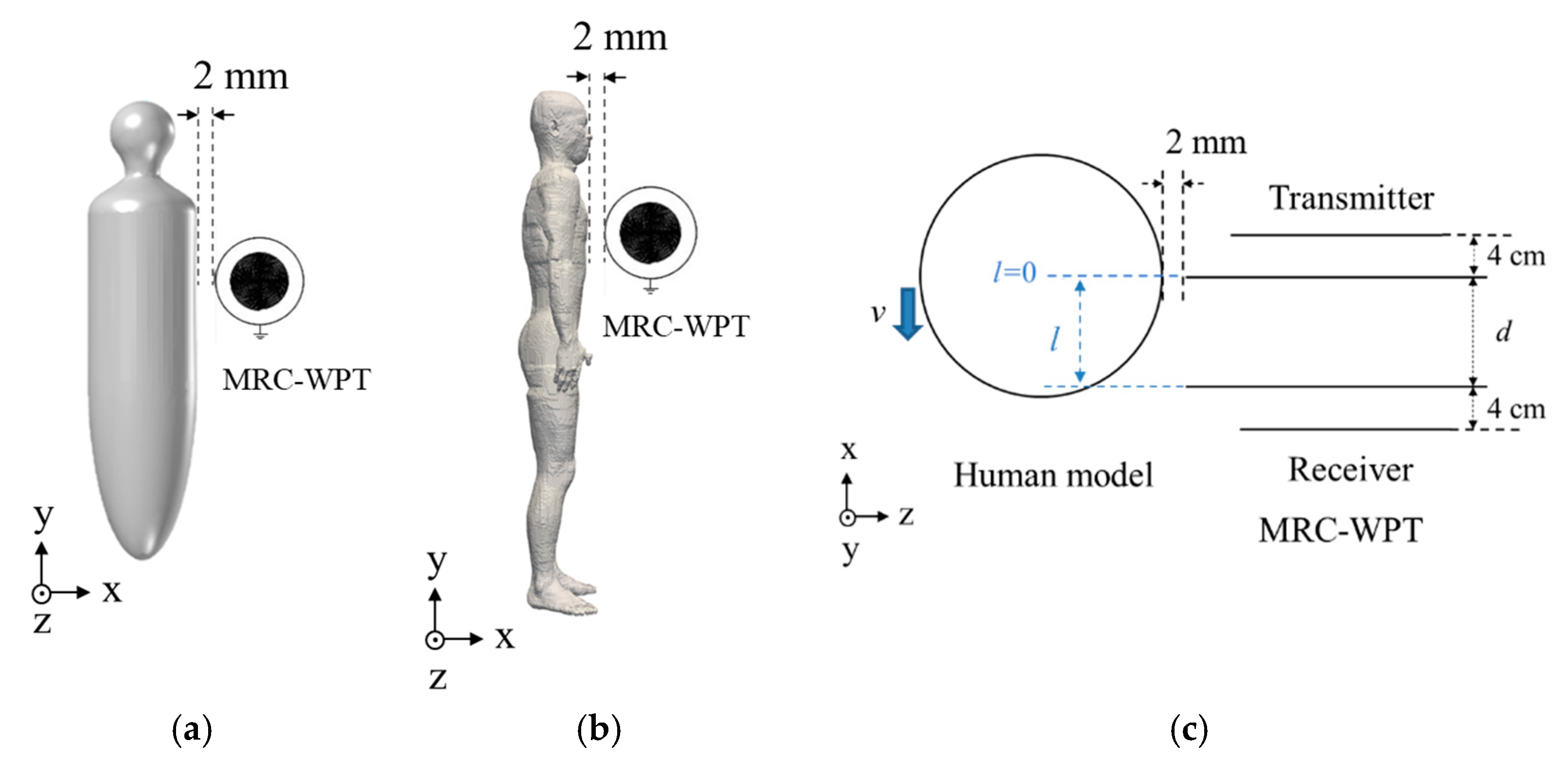
2.1. Geometric Structure of the Proposed MRC-WPT System

This paper discusses the variations of an MRC-WPT system using different resonators. As shown in Figure 1a, in this study we adopted a four-coil MRC-WPT system. The transmitter and receiver are composed of a single-loop coil and a resonator. The distance between the single-loop coil and resonator was set to 4 cm, where the quality factor of the two resonators is most equal. Two types of resonators were considered: a conventional resonator and our proposed resonator structure. The conventional resonator consisted of a spiral coil, as shown in Figure 1b (referred to here as a non-grounded resonator). As shown in Figure 1c, the proposed resonator aims to reduce the coupling between the WPT system and the human body, using a grounded single-loop coil around the spiral coil. The spiral coil and grounded loop were coaxially located on the same plane. This resonator is hereafter referred to as a “grounded resonator” for simplicity. The receiver structure of the MRC-WPT system was identical to that of the transmitter [40]. The geometric parameters of the spiral resonator were determined using its self-resonant frequency and quality factor [41]. In Figure 1a, κTR represents the coupling coefficient between the transmitter (denoted as T) and receiver (denoted as R). Resistance is connected to the receiving coil, imitating the load. All coils used in this study were made of 1-mm-diameter copper wire. Copper wire is widely used in laboratory and industrial applications for WPT systems in different thicknesses/diameters. [42] showed that 1 mm-diameter copper wire has more transmission efficiency than other diameters. Therefore, this study adopted the 1-mm-diameter copper wire. The working frequency was set to 13.56 MHz since this is a promising frequency for WPT applications in industrial, scientific, and medical fields [16,34,43].

2.2. Transmission Efficiency of the Proposed MRC-WPT System

When the transmitter and receiver are in resonance, the transmission efficiency of the WPT system can be calculated using Equation (1) based on the coupled-mode theory [1,44].
η = Γ W κ T R 2 Γ R 2 Γ T [ ( 1 + Γ W Γ R ) κ T R 2 Γ T Γ R ] + ( 1 + Γ W Γ R ) 2
where κTR is the coupling coefficient, ΓT/R denotes the attenuation rates of the transmitter and receiver due to ohmic and radiation losses, and ΓW refers to the attenuation rates of the load [1]. Thus, efficient transmission occurs when the MRC-WPT system operates in a strongly coupled system, i.e., κTR2/ΓTΓR > 1. The variables ΓT and ΓR can be calculated using Equation (2).
Γ = ω 0 / 2 Q ,
where ω0 is the resonant angular frequency of the resonator and Q = ω0 L/R is the quality factor of the transmitter or receiver.
Figure 2 shows the equivalent lumped-circuit model of the four-coil MRC-WPT system [1]. The signal power of the transmitter part generated by voltage source VS is transferred to the receiver part at resonant frequency f0 and is then delivered to load RL. The transmitter and receiver can be represented by series inductors (L1 and L2) and resistances (R1 and R2). The parameter R1 and R2 represent the resistances due to the ohmic and radiation losses of the transmitter and receiver [42]. The function M = κTR (L1 × L2)1/2 represents the mutual inductance. Capacitors C1 and C2 are used to tweak the transmitter and receiver resonance to the desired frequency [45].
In this study, the voltage source is applied without considering impedance matching [46]. Therefore, the transmission efficiency η of the entire WPT system (blue dashed box in Figure 2) can be calculated as the ratio between the actual input power at port 1–1′, i.e., Pin, and actual output power PRL, which is expressed as follows:
η = P R L P i n

2.3. Human-Body Model

The human-body models adopted in this study are shown in Figure 3. As shown in Figure 3a, a homogeneous axial-symmetric human model was adopted from the IEC62233 standard [47] to evaluate the mutual interaction between the MRC-WPT system and a human body in the vicinity. Its height and maximum diameters were 1.528 and 0.35 m, respectively, which approximated the size of an adult human body. In addition, the dielectric properties of the homogeneous model were set to two-thirds of those of a muscle, an approach which is often used to represent the average electrical properties of a human body [14].
Anatomical body models have been widely adopted in dosimetry studies and have been considered by ICNIRP to relate RL with BR. In the present work, the Japanese adult male model, TARO [28], shown in Figure 3b, developed by the National Institute of Information and Communication Technology, Tokyo, Japan, was adopted for a detailed assessment of the exposure dose in a realistic human body. This voxel-based model consisted of 51 tissues and organs, and its spatial resolution was 2 mm. The dielectric properties of the tissues were obtained from the four-Cole–Cole dispersion model [48].

2.4. Exposure Scenarios

The WPT system was installed at the body model’s chest level, as shown in Figure 4a,b. The separation between the grounded loops and the body model was 2 mm. Different locations of the human-body model were considered in this study to analyze the mutual interaction between the human body and the WPT system. Three exposure cases, corresponding to three body locations relative to the WPT system, were considered for each WPT system. These are Case A (l = 0), Case B (l = d/2), and Case C (l = d), where d is the distance between the transmitter and receiver, and l is the distance to the center of the human model, as shown in Figure 4c.

2.5. Simulation of Mutual Interaction

The finite-element method in COMSOL Multiphysics 5.3 commercial software was used [49] to evaluate the mutual interactions between the human body and the MRC-WPT system. The circuit shown in Figure 2 was coupled using the COMSOL field-circuit co-simulation method to evaluate the transmission efficiency [49,50,51]. The simulation domain was a 1.2-m-diameter sphere, which enclosed the WPT system. An absorbing boundary condition was applied to the surface of the sphere. The coil materials were set to copper, which came with the software. The parameters L, ω0, and R were calculated using the frequency domain solver of the full-wave electromagnetic simulation package COMSOL Multiphysics 5.3. Compensation capacitors C1 and C2 were used to make the transmitter and receiver resonant at the desired frequency [45], in which the lumped inductances were numerically extracted using COMSOL Multiphysics 5.3. The theoretical maximum transmission efficiency was obtained by adjusting the load impedance RL [1]. The dependence of transmission efficiency on the transmission distance d for the matched state of the MRC-WPT system with grounded and non-grounded resonators was evaluated using Equation (3) based on the processes mentioned above. The stray magnetic field was also evaluated at the same time.
To simulate the human-system interaction, the simplified homogeneous human body, as shown in Figure 3a, was adopted in this analysis due to the difficulties in handling fine-resolution voxel-based body models. Tetrahedral meshes were used to discretize the simulation domain, and the software automatically determined the mesh sizes. We compared the results using finer settings, and the calculations indicated that the applied discretization resolution did not affect the results.

2.6. Simulation of Exposure Dose in the TARO Model

To assess the impact of the exposure dose in a realistic anatomical human-body model (TARO), the magnetic vector potential values were first calculated using the stray magnetic fields simulated using COMSOL Multiphysics 5.3 in the absence of a body model [33]. Next, the induced electric field was computed by means of an in-house-developed solver using the SPFD method. The convergence was accelerated using the geometric multigrid method [52]. The magnetic vector potential values were used as the source of the SPFD computation, which represented the scenario of exposure to the external WPT magnetic field. The applicability of this two-step approach was confirmed by [22]. The presence of the human body did not perturb the external magnetic field distribution, and the displacement current could be neglected at low frequency. Subsequently, the specific absorption rate (SAR) in each voxel was evaluated from the electric field using the “mid-ordinate” algorithm [53]. The spatial-average SAR value was determined by averaging the local SAR with more than 10 g of cubical volume using the method described in [54]. The peak spatial-average SAR (psSAR) averaged over 10 g of tissues and the whole-body average SAR were computed. All computational results were normalized to an input power of 1 W in the MRC-WPT system.

3. Results and Discussion

3.1. Validation of the MRC-WPT System Computation

We compared the calculated transmission efficiency with our experimental results [40] to validate our computational model. The experiment result was expressed as η E x = 10 | S 21 | 10 1 10 | S 11 | 10 × 100   (%) [55], and the COMSOL results were evaluated using Equation (3). In the experimental study, the resonant frequency of the WPT system was set to 10 MHz. Therefore, the operating frequency of the computational model was adjusted to 10 MHz. This may not violate the generality principle as the frequency and coil length are inversely proportional to each other. Figure 5 shows the differences between the computation and measurement results. The transmission efficiency was within approximately 5% of the difference (the change was most significant when using ungrounded resonators with a transmission distance of 0.21 m), which validated the computational methods used in the current study.

3.2. Interactions between the Human Body and MRC-WPT System

The frequency characteristics of the S parameter of the two WPT systems with and without the presence of a human body are shown in Figure 6. A source and load impedance of 50 Ω was assumed. The WPT reflection coefficient (S11), corresponding to a grounded resonator with and without a human-body model, was lower than that of the WPT with a non-grounded resonator. The bandwidth characteristics of the two resonator types were also different. The narrower peak for the grounded resonator is a clear indicator that the Q value is higher than that of the non-grounded resonator, indicating an increase in transmission efficiency. The simulation results in Figure 6 suggest that the grounded loop could mitigate the reflection coefficient changes and suppress the electric field strength.
The S11 values of the two WPTs with and without a human model at their resonant frequencies are listed in Table 1. The resonant frequency was set to 13.56 ± 0.01 MHz. The S11 values of the WPT with a non-grounded resonator varied from −8.16 to −6.06 dB when the human model was considered. Meanwhile, the S11 values of the WPT with a grounded resonator varied from −14.97 to −14.1 dB. This result implied that the grounded resonator suppressed the interaction of the human model with the WPT performance. As a result, the bandwidths of the curves in Figure 6 became wider, indicating reduced quality factors with human models.
Figure 7 shows the transmission efficiencies at different transmission distances d. The solid curves in Figure 7 show that the transmission efficiency gradually decreased with increasing the transmission distance d because of the decreasing coupling coefficient between the transmitter and receiver [56]. In addition, the transmission efficiency of the MRC-WPT system with a grounded resonator exhibited slightly better performance than the non-grounded resonator at d < 23 cm. Next, we considered the effects of the presence of a human body on the transmission efficiencies of the two types of MRC-WPT systems at different body locations with the increase in the transmission distance. The markers in Figure 7 showed small increases in the transmission efficiencies when the human body was close to both systems. For example, at d < 10 cm, the variations in transmission efficiencies were marginal for the two systems. However, the influence of the human body reduced the transmission efficiency by up to 10 percentage points at a maximum distance of 25 cm. Altogether, the variation in transmission efficiency is marginal at different body locations (i.e., cases A, B, and C), mainly due to the size of the human body being larger than the transmission distance.
The quality factors and coupling coefficients of the two MRC-WPT systems with and without a human-body model at d = 9 cm are listed in Table 2. The presence of a human body caused an approximately 3% variation in the quality factor in the non-grounded resonator, whereas it was around 0.5% in the grounded resonator. For the coupling coefficients, the presence of a human body caused a nearly 11.4% variation in the non-grounded resonator and a 26.2% approximated variation in the grounded resonator. In general, the proposed grounded resonator increased the quality factors and coupling coefficients of the MRC-WPT system, which led to slightly improved transmission efficiency compared with the system with a non-grounded resonator. The results listed in Table 2 indicate that the presence of a human body significantly affects the coupling coefficients of both WPT systems in short-range transmission.
The electric field distributions of the two MRC-WPT systems were also calculated. Figure 8a shows that the grounded loop concentrated the electromagnetic fields around the MRC-WPT systems. A section of the gray data line in Figure 8a is shown in Figure 8b to illustrate the electric field’s strength inside and outside the grounded loop. The origin of the coordinates in Figure 8b was set to a point in the grounded loop. In addition, Figure 8b confirmed that the electric field outside the grounded loop was reduced compared with that in the WPT system with a non-grounded resonator. The electric field distribution results were also consistent with those derived from S11 [14].

3.3. Exposure Doses in the TARO Model

An in-house-developed SPFD solver was used to calculate the induced electric field and local SAR in the TARO model using 1-W transmission power for the two types of resonators at 13.56 MHz, where the distance between the transmitter and receiver, denoted as d, was 9 cm (the distance at maximum system efficiency). The locations of MRC-WPT relative to TARO are shown in Figure 4b,c. Figure 9 and Figure 10 show the induced electric field and local SAR distributions, respectively. In all cases, hotspots appeared around the chest in the TARO model, the closest body part to WPT. Reductions in the induced electric field and SAR in TARO were observed in the WPT with a grounded resonator. The simulation results shown in Figure 9 and Figure 10 indicate that the induced electric field and SAR in the human body were reduced in the MRC-WPT system with a grounded resonator. This was mainly caused by the grounded loop that suppressed the leakage of the electromagnetic field around the MRC-WPT system, resulting in interaction with the human-body model.
The maximum induced electric field strengths, psSAR, and whole-body average SAR for all simulated cases (A, B, and C) are listed in Table 3, Table 4 and Table 5. The induced electric fields and SARs of the different body model locations in the grounded resonator were comparable. The grounded resonator of the MRC-WPT system reduced the internal doses in the TARO model. A maximum reduction in the induced electric field strength of 43.6% was observed in the MRC-WPT system with a grounded resonator compared with a non-grounded resonator. An approximately 60% reduction in psSAR and whole-body average SAR was observed in the grounded type, confirming the decrease in the human body exposure doses using the proposed grounded resonators.
According to the ICNIRP guidelines, the general public’s psSAR and whole-body average SAR limits are 2 and 0.08 W/kg, respectively [23]. The results listed in Table 4 and Table 5 show that the whole-body average SAR was more restrictive than psSAR in the MRC-WPT system and the exposure scenarios considered in the present study. By applying the psSAR limit, the maximum permissible input power of the grounded MRC-WPT was 40.0 kW, whereas it was 14.8 kW for the non-grounded MRC-WPT system. By applying the whole-body average SAR limit, the maximum permissible transmission power values were found to be 33.5 and 13.1 kW for the MRC-WPT systems with grounded and non-grounded resonators, respectively.
Existing WPT systems are based on the magnetic coupling of several tens of kilohertz to tens of megahertz frequency ranges. According to the different working frequencies, the desired physical quantities of BRs differed. At over 100 kHz, psSAR and whole-body SAR were used as BRs to protect against adverse heating effects. Below 10 MHz, BR was defined as the induced electric field to shield from the stimulation effect. Therefore, the induced electric field and SARs must be considered within the range of 100 kHz to 10 MHz. The computation results for the magnetic-coupled WPT [12] suggested that under approximately 300–400 kHz, the induced electric field was more restrictive than psSAR. Another study showed that the average whole-body SAR could be more dominant at higher frequencies [57]. However, variations in the whole-body average SAR could be high because it depends on the body weight, posture, the volume of the exposed body, coil size, materials, and source configuration [58]. These issues require further investigations.
In our simulations, the separation between the torso and border of the resonator was set to 2 mm, which was much smaller than the generally used measurement distance (mostly 20 or 30 cm) specified in IEC 62233 for determining the electromagnetic field around household appliances. Such standardization is currently being performed for WPT. Nonetheless, the calculated values could provide a rough (more conservative) estimate of the exposure doses of a WPT device with similar configurations.

4. Conclusions

In this study we proposed a modified resonator with a grounded loop for an MRC-WPT system to mitigate its interaction with the human body and obtain efficient short-range power transfers. The two systems’ electromagnetic field distributions, performance, and human safety assessments were discussed and compared. The full-wave simulation results demonstrated that the transmission efficiency improved in the proposed grounded resonator. The strength of the electric field outside the grounded loop was reduced. The transmission efficiency was also insensitive to the proximity of the human body. Considering the interaction between the human body and the system, the grounded resonator reduced the exposure doses in the human body compared with the MRC-WPT with a non-grounded resonator. The maximum induced electric field strength and the SAR values in the human body were reduced by 43.6% and 69.7%, respectively, using the proposed resonator. In the worst-case exposure scenario considered in this work, the maximum allowable input power was 33.5 kW when the grounded resonator was used in compliance with the prescribed ICNIRP limit for the whole-body averaged SAR, compared with 13.1 kW for the MRC-WPT with non-grounded resonators. The proposed resonators mentioned in the paper provide further information on the safe design of WPT systems. The resonator could be used in the future for electric vehicles and household applications.

Author Contributions

Conceptualization, H.H. and A.H.; methodology, Y.D.; validation, X.D., Y.D. and M.H.; formal analysis, X.D.; investigation, J.L., Y.D., J.G.-T., G.F. and A.H.; data curation, X.D. and H.H.; writing—original draft preparation, X.D. and J.L.; writing—review and editing, Y.D., J.G.-T., H.H., M.H., G.F. and A.H.; visualization, X.D.; supervision, M.H. and G.F.; project administration, J.L. and H.H. All authors have read and agreed to the published version of the manuscript.

Funding

This research was funded by Japan Society for the Promotion of Science: Japanese-German Graduate Externship (Grant No. 2019/R1).

Institutional Review Board Statement

Not applicable.

Informed Consent Statement

Not applicable.

Data Availability Statement

Not applicable.

Acknowledgments

This work was partly supported by the JSPS Japanese-German Graduate Externship (Grant No. 2019/R1).

Conflicts of Interest

The authors declare no conflict of interest.

References

  1. Kurs, A.; Karalis, A.; Moffatt, R.; Joannopoulos, J.D.; Fisher, P.; Soljačić, M. Wireless power transfer via strongly coupled magnetic resonances. Science 2007, 317, 83–86. [Google Scholar] [CrossRef] [Green Version]
  2. Ho, S.L.; Wang, J.; Fu, W.N.; Sun, M. A Comparative Study Between Novel Witricity and Traditional Inductive Magnetic Coupling in Wireless Charging. IEEE Trans. Magn. 2011, 47, 1522–1525. [Google Scholar] [CrossRef]
  3. Houran, M.A.; Yang, X.; Chen, W. Magnetically coupled resonance wpt: Review of compensation topologies, resonator structures with misalignment, and emi diagnostics. Electronics 2018, 7, 296. [Google Scholar] [CrossRef] [Green Version]
  4. Abdelhafeez, M.; Yousef, K.; Abdelraheem, M.; Khaled, E.E.M. Design of 6 GHz High Efficiency Long Range Wireless Power Transfer System Using Offset Reflectors fed by Conical Horns. In Proceedings of the 2019 International Conference on Innovative Trends in Computer Engineering ITCE 2019, Aswan, Egypt, 2–4 February 2019; pp. 365–370. [Google Scholar] [CrossRef]
  5. Karalis, A.; Joannopoulos, J.D.; Soljačić, M. Efficient wireless non-radiative mid-range energy transfer. Ann. Phys. 2008, 323, 34–48. [Google Scholar] [CrossRef] [Green Version]
  6. Alashgar, D.; Fujiwara, K.; Nagaoka, N. Fundamental Investigation of Short-Range Inductive Coupling Wireless Power Transmission by Using Series-Series Capacitive Compensation Topology. J. Asian Electr. Veh. 2019, 17, 1811–1822. [Google Scholar] [CrossRef]
  7. Zhang, Y.; Lu, T.; Zhao, Z.; He, F.; Chen, K.; Yuan, L. Employing Load Coils for Multiple Loads of Resonant Wireless Power Transfer. IEEE Trans. Power Electron. 2015, 30, 6174–6181. [Google Scholar] [CrossRef]
  8. Pusti, A.; Das, P.K.; Panda, A.K.; Padhi, J.; Kar, D.P. Essential analysis of MRC-WPT system for electric vehicle charging using coupled mode theory. In Proceedings of the 2021 1st Odisha International Conference on Electrical Power Engineering, Communication and Computing Technology (ODICON), Bhubaneswar, India, 8–9 January 2021; pp. 1–5. [Google Scholar] [CrossRef]
  9. Tan, L.; Elnail, K.E.I.; Ju, M.; Huang, X. Comparative analysis and design of the shielding techniques in WPT systems for charging EVs. Energies 2019, 12, 2115. [Google Scholar] [CrossRef] [Green Version]
  10. Mohamadi, T. Working frequency in wireless power transfer for implantable biomedical sensors. In Proceedings of the 2011 International Conference on Electrical Engineering and Informatics, Bandung, Indonesia, 17–19 July 2011; pp. 1–5. [Google Scholar] [CrossRef]
  11. Zakaria, N.A.; Jusoh, M.; Ghazali, N.H.; Yasin, M.N.; Sabapathy, T.; Osman, M.N.; Ahmad, N.; Zakaria, M.Z. A Computational Study on the Magnetic Resonance Coupling Technique for Wireless Power Transfer. MATEC Web Conf. 2017, 140, 01025. [Google Scholar] [CrossRef] [Green Version]
  12. Campi, T.; Cruciani, S.; Palandrani, F.; de Santis, V.; Hirata, A.; Feliziani, M. Wireless Power Transfer Charging System for AIMDs and Pacemakers. IEEE Trans. Microw. Theory Tech. 2016, 64, 633–642. [Google Scholar] [CrossRef]
  13. Arai, T.; Hirayama, H. Folded spiral resonator with double-layered structure for near-field wireless power transfer. Energies 2020, 13, 1581. [Google Scholar] [CrossRef] [Green Version]
  14. Kumazawa, A.; Diao, Y.; Hirata, A.; Hirayama, H. Reduction of Human Interaction with Wireless Power Transfer System Using Shielded Loop Coil. Electronics 2020, 9, 953. [Google Scholar] [CrossRef]
  15. Laakso, I.; Tsuchida, S.; Hirata, A.; Kamimura, Y. Evaluation of SAR in a human body model due to wireless power transmission in the 10MHz band. Phys. Med. Biol. 2012, 57, 4991–5002. [Google Scholar] [CrossRef]
  16. Park, S.W. Misaligned effect and exposure assessment for wireless power transfer system using the anatomical whole-body human model. Prog. Electromagn. Res. C 2017, 77, 19–28. [Google Scholar] [CrossRef] [Green Version]
  17. Škiljo, M.; Blažević, Z.; Poljak, D. Interaction between human and near-field of wireless power transfer system. Prog. Electromagn. Res. C 2016, 67, 1–10. [Google Scholar] [CrossRef] [Green Version]
  18. Hikage, T.; Yamagishi, M.; Shindo, K.; Nojima, T. Active implantable medical device EMI estimation for EV-charging WPT system based on 3D full-wave analysis. In Proceedings of the 2017 Asia-Pacific International Symposium on EMC (APEMC), Seoul, Korea, 20–23 June 2017; pp. 87–89. [Google Scholar] [CrossRef]
  19. Campi, T.; Cruciani, S.; de Santis, V.; Maradei, F.; Feliziani, M. EMC and EMF safety issues in wireless charging system for an electric vehicle (EV). In Proceedings of the 2017 International Conference of Electrical and Electronic Technologies for Automotive, Torino, Italy, 15–16 June 2017; pp. 23–26. [Google Scholar] [CrossRef]
  20. Lyu, Y.L.; Meng, F.Y.; Yang, G.H.; Che, B.J.; Wu, Q.; Sun, L.; Erni, D.; Li, J.L.W. A Method of Using Nonidentical Resonant Coils for Frequency Splitting Elimination in Wireless Power Transfer. IEEE Trans. Power Electron. 2015, 30, 6097–6107. [Google Scholar] [CrossRef]
  21. Hirata, A.; Diao, Y.; Onishi, T.; Sasaki, K.; Ahn, S.; Colombi, D.; de Santis, V.; Laakso, I.; Giaccone, L.; Joseph, W.; et al. Assessment of Human Exposure to Electromagnetic Fields: Review and Future Directions. IEEE Trans. Electromagn. Compat. 2021, 63, 1619–1630. [Google Scholar] [CrossRef]
  22. Hirata, A.; Ito, F.; Laakso, I. Confirmation of quasi-static approximation in SAR evaluation for a wireless power transfer system. Phys. Med. Biol. 2013, 58, N241–N249. [Google Scholar] [CrossRef] [PubMed]
  23. ICNIRP. Guidelines for limiting exposure to electromagnetic fields (100 kHz to 300 GHz). Health Phys. 2020, 118, 483–524. [Google Scholar] [CrossRef] [PubMed]
  24. IEEE. IEEE standard for safety levels with respect to human exposure to electric, magnetic, and electromagnetic fields, 0 Hz to 300 GHz-corrigenda 2. In IEEE Std C95.1-2019/Cor2-2020 (Corrigenda to IEEE Std C95.1-2019); IEEE: New York, NY, USA, 21 October 2020; pp. 1–15. [Google Scholar] [CrossRef]
  25. Ziegelberger, G.; van Rongen, E.; Croft, R.; Feychting, M.; Green, A.C.; Hirata, A.; d’Inzeo, G.; Marino, C.; Miller, S.; Oftedal, G.; et al. Principles for non-ionizing radiation protection. Health Phys. 2020, 118, 477–482. [Google Scholar] [CrossRef]
  26. Hoang, L.H.; Scorretti, R.; Burais, N.; Voyer, D. Numerical dosimetry of induced phenomena in the human body by a three-phase power line. IEEE Trans. Magn. 2009, 45, 1666–1669. [Google Scholar] [CrossRef] [Green Version]
  27. Chatterjee, I.; Gu, Y.G.; Gandhi, O.P. Quantification of Electromagnetic Absorption in Humans from Body-Mounted Communication Transceivers. IEEE Trans. Veh. Technol. 1985, 34, 55–62. [Google Scholar] [CrossRef]
  28. Nagaoka, T.; Watanabe, S.; Sakurai, K.; Kunieda, E.; Watanabe, S.; Taki, M.; Yamanaka, Y. Development of realistic high-resolution whole-body voxel models of Japanese adult males and females of average height and weight, and application of models to radio-frequency electromagnetic-field dosimetry. Phys. Med. Biol. 2004, 49, 1–15. [Google Scholar] [CrossRef]
  29. Park, S.W. Investigating human exposure to a practical wireless power transfer system using and the effect about key parameters of dosimetry. PLoS ONE 2020, 15, e0236929. [Google Scholar] [CrossRef]
  30. Park, S.W. Dosimetry for Resonance-Based Wireless Power Transfer Charging of Electric Vehicles. J. Electromagn. Eng. Sci. 2015, 15, 129–133. [Google Scholar] [CrossRef]
  31. Arduino, A.; Bottauscio, O.; Chiampi, M.; Giaccone, L.; Liorni, I.; Kuster, N.; Zilberti, L.; Zucca, M. Accuracy Assessment of Numerical Dosimetry for the Evaluation of Human Exposure to Electric Vehicle Inductive Charging Systems. IEEE Trans. Electromagn. Compat. 2020, 62, 1939–1950. [Google Scholar] [CrossRef]
  32. Miwa, K.; Takenaka, T.; Hirata, A. Electromagnetic Dosimetry and Compliance for Wireless Power Transfer Systems in Vehicles. IEEE Trans. Electromagn. Compat. 2019, 61, 2024–2030. [Google Scholar] [CrossRef]
  33. Shimamoto, T.; Laakso, I.; Hirata, A. In-situ electric field in human body model in different postures for wireless power transfer system in an electrical vehicle. Phys. Med. Biol. 2015, 60, 163–173. [Google Scholar] [CrossRef]
  34. Perhirin, S.; Auffret, Y. Influence of fields and SAR evaluation for 13.56 MHz EV resonance-based wireless power charging systems. Microw. Opt. Technol. Lett. 2013, 55, 2562–2568. [Google Scholar] [CrossRef]
  35. Nadakuduti, J.; Douglas, M.; Lu, L.; Christ, A.; Guckian, P.; Kuster, N. Compliance Testing Methodology for Wireless Power Transfer Systems. IEEE Trans. Power Electron. 2015, 30, 6264–6273. [Google Scholar] [CrossRef]
  36. Sunohara, T.; Hirata, A.; Laakso, I.; de Santis, V.; Onishi, T. Evaluation of nonuniform field exposures with coupling factors. Phys. Med. Biol. 2015, 60, 8129–8140. [Google Scholar] [CrossRef]
  37. Wake, K.; Laakso, I.; Hirata, A. Derivation of coupling factors for different wireless power transfer systems: Inter- and intralaboratory comparison. IEEE Trans. Electromagn. Compat. 2016, 59, 1–9. [Google Scholar] [CrossRef]
  38. Zhang, W.; White, J.C.; Malhan, R.K.; Mi, C.C. Loosely Coupled Transformer Coil Design to Minimize EMF Radiation in Concerned Areas. IEEE Trans. Veh. Technol. 2016, 65, 4779–4789. [Google Scholar] [CrossRef]
  39. Campi, T.; Cruciani, S.; Maradei, F.; Feliziani, M. Near-Field Reduction in a Wireless Power Transfer System Using LCC Compensation. IEEE Trans. Electromagn. Compat. 2017, 59, 686–694. [Google Scholar] [CrossRef]
  40. Duan, X.; Norodin, N.S.A.; Sakata, A.; Hotta, M. Fundamental characteristics of some modified shape spiral-resonators used for resonator-coupled type wireless power transfer system. In Proceedings of the 21th IEEE Hiroshima Section Student Symposium (HISS), Okayama, Japan, 9–10 November 2019; pp. 294–297. [Google Scholar]
  41. Hotta, M.; Norodin, N.S.A.; Zakaria, N.N.M.; Onari, H.; Takegami, T. Influence of lossy objects for resonator-coupled type wireless power transfer system with coplanar dual-spiral resonators. In Proceedings of the Asia-Pacific Microwave Conference APMC, Kyoto, Japan, 6–9 November 2018; pp. 40–42. [Google Scholar] [CrossRef]
  42. Campi, T.; Cruciani, S.; Maradei, F.; Feliziani, M. Magnetic shielding design of wireless power transfer systems. Annu. Rev. Prog. Appl. Comput. Electromagn. 2015, 2015, 13–14. [Google Scholar]
  43. Xue, R.; Cheng, K.; Je, M. High-Efficiency Wireless Power Transfer for Biomedical Implants by Optimal. IEEE Trans. Circuits Syst. I Regul. Pap. 2013, 60, 867–874. [Google Scholar] [CrossRef]
  44. Haus, H.A. Waves and fields in optoelectronics. In CEUR Workshop Proceedings; Prentice Hall: Hoboken, NJ, USA, 1984; p. 897. [Google Scholar]
  45. Wang, C.S.; Covic, G.A.; Stielau, O.H. Power transfer capability and bifurcation phenomena of loosely coupled inductive power transfer systems. IEEE Trans. Ind. Electron. 2004, 51, 148–157. [Google Scholar] [CrossRef]
  46. Hirayama, H.; Ozawa, T.; Hiraiwa, Y.; Kikuma, N.; Sakakibara, K. A consideration of electro-magnetic-resonant coupling mode in wireless power transmission. IEICE Electron. Express 2009, 6, 1421–1425. [Google Scholar] [CrossRef] [Green Version]
  47. IEC62233. Measurement methods for electromagnetic fields of household appliances and similar apparatus with regard to human exposure. Int. Electrotech. Comm. 2008, 3, 33–34. [Google Scholar]
  48. Gabriel, S.; Lau, R.W.; Gabriel, C. The dielectric properties of biological tissues: III. Parametric models for the dielectric spectrum of tissues. Phys. Med. Biol. 1996, 41, 2271–2293. [Google Scholar] [CrossRef] [PubMed] [Green Version]
  49. Pico, J.; Bechtold, T.; Hohlfeld, D. Model order reduction using COMSOL Multiphysics® Software—A compact model of a wireless power transfer system. In Proceedings of the 2016 COMSOL Conference, Munich, Germany, 12–14 October 2016; pp. 4–6. [Google Scholar]
  50. Kaufmann, C.; Günther, M.; Klagges, D.; Knorrenschild, M.; Richwin, M.; Schöps, S.; ter Maten, E.J.W. Efficient frequency-transient co-simulation of coupled heat-electromagnetic problems. J. Math. Ind. 2014, 4, 1–3. [Google Scholar] [CrossRef] [Green Version]
  51. Tierney, B.B.; Grbic, A. Planar Shielded-Loop Resonators. IEEE Trans. Antennas Propag. 2014, 62, 3310–3320. [Google Scholar] [CrossRef]
  52. Laakso, I.; Hirata, A. Fast multigrid-based computation of the induced electric field for transcranial magnetic stimulation. Phys. Med. Biol. 2012, 57, 7753–7765. [Google Scholar] [CrossRef] [PubMed]
  53. Laakso, I.; Uusitupa, T.; Ilvonen, S. Comparison of SAR calculation algorithms for the finite-difference time-domain method. Phys. Med. Biol. 2010, 55, N421. [Google Scholar] [CrossRef] [PubMed] [Green Version]
  54. IEEE. Recommended practice for measurements and computations of radio frequency electromagnetic fields with respect to human exposure to Such Fields, 100 kHz–300 GHz. In IEEE Std C95.3-2002 (Revision of IEEE Std C95.3-1991); IEEE: New York, NY, USA, 2002; p. i-126. [Google Scholar] [CrossRef]
  55. Norodin, N.S.A.; Nakamura, K.; Hotta, M. Effects of Lossy Mediums for Resonator-Coupled Type Wireless Power Transfer System using Conventional Single- and Dual-Spiral Resonators. IEICE Trans. Electron. 2021, E105-C. [Google Scholar] [CrossRef]
  56. Awai, I.; Zhang, Y.; Komori, T.; Ishizaki, T. Coupling coefficient of spiral resonators used for wireless power transfer. In Proceedings of the Asia-Pacific Microwave Conference APMC, Yokohama, Japan, 7–9 December 2010; pp. 1328–1331. [Google Scholar]
  57. Christ, A.; Douglas, M.G.; Roman, J.M.; Cooper, E.B.; Sample, A.P.; Waters, B.H.; Smith, J.R.; Kuster, N. Evaluation of Wireless Resonant Power Transfer Systems With Human Electromagnetic Exposure Limits. IEEE Trans. Electromagn. Compat. 2013, 55, 265–274. [Google Scholar] [CrossRef]
  58. Rašić, P.; Škiljo, M.; Blažević, Z.; Dorić, V.; Poljak, D. Simulation of human body exposure to near field of high and low RF wireless power transfer systems. Int. J. Eng. Model. 2020, 33, 19–36. [Google Scholar] [CrossRef]
Figure 1. Geometrical structure of the proposed MRC-WPT system. (a) Four-coil MRC-WPT system. (b) Non-grounded resonator. (c) Proposed resonator with a grounded loop.
Energies 14 07253 g001
Figure 2. Equivalent lumped-circuit model of the four-coil MRC-WPT system.
Energies 14 07253 g002
Figure 3. Human-body model. (a) Homogeneous axial-symmetric human model. (b) Japanese adult male model TARO.
Energies 14 07253 g003
Figure 4. The MRC-WPT with respect to the (a) homogeneous body and (b) TARO models. (c) Top view of the MRC-WPT and homogenous human model.
Energies 14 07253 g004
Figure 5. Experimental validation of transmission efficiency of MRC-WPTs’ two resonator types (10 MHz).
Energies 14 07253 g005
Figure 6. S parameters (S11) for the two resonators.
Energies 14 07253 g006
Figure 7. Dependence of transmission efficiency on d in Case A (l = 0), Case B (l = d/2), and Case C (l = d), and without a human model for a (a) non-grounded and (b) grounded resonator.
Energies 14 07253 g007
Figure 8. Electromagnetic-field distribution of two 13.56-MHz MRC-WPT systems without a human model when the input power is 1 W and the transmission distance d = 9 cm. (a) Electric and magnetic field distributions around the WPT systems. (b) Electric field on a horizontal line. The gray circle illustrates the location of the grounded loop.
Energies 14 07253 g008
Figure 9. Induced electric field distribution on TARO. (a) Body surface. (b) Cross-sectional plane of input power 1 W, and transmission distance d = 9 cm.
Energies 14 07253 g009
Figure 10. Local SAR distributions on TARO. (a) Body surface. (b) Cross-sectional plane of input power 1 W, and transmission distance d = 9 cm.
Energies 14 07253 g010
Table 1. S11 (dB) of the two WPT systems with and without a human-body model at resonant frequency.
Resonator TypeFrequency (MHz)Without Human BodyWith Human Body
Non-grounded13.55−8.16−6.06
Grounded13.57−14.97−14.10
Table 2. Quality factor and coupling coefficient of the MRC-WPT systems for two types of resonators, d = 9 cm.
ResonatorQuality FactorCoupling Coefficient
Without Human BodyWith Human BodyWithout Human BodyWith Human Body
Non-grounded215.4222.70.1280.144
Grounded234.2235.30.1460.198
Table 3. Maximum induced electric field strength (V/m). RD refers to relative difference.
Model DisplacementNon-GroundedGroundedRD
Case A3.441.9443.6%
Case B3.222.0237.3%
Case C2.981.8537.9%
Table 4. Maximum psSAR10g (W/kg). RD refers to relative difference.
Model DisplacementNon-GroundedGroundedRD
Case A1.88 × 10−40.57 × 10−469.7%
Case B2.04 × 10−40.67 × 10−467.1%
Case C1.35 × 10−40.50 × 10−463.0%
Table 5. Whole-body average SAR (W/kg). RD refers to relative difference.
Model DisplacementNon-GroundedGroundedRD
Case A8.34 × 10−62.87 × 10−665.6%
Case B7.94 × 10−63.48 × 10−656.1%
Case C6.12 × 10−62.39 × 10−661.0%
Publisher’s Note: MDPI stays neutral with regard to jurisdictional claims in published maps and institutional affiliations.

