Article

A Rapid Method for Low Temperature Microencapsulation of Phase Change Materials (PCMs) Using a Coiled Tube Ultraviolet Reactor

by
Jawaad A. Ansari
1,
Refat Al-Shannaq
1,
Jamal Kurdi
2,
Shaheen A. Al-Muhtaseb
3,
Charles A. Ikutegbe
1 and
Mohammed M. Farid
1,*
1
Department of Chemical and Materials Engineering, The University of Auckland, Private Bag 92019, Auckland 1142, New Zealand
2
Engineering Technology-Chemical Processing, College of the North Atlantic-Qatar, Doha P.O. Box 24449, Qatar
3
Department of Chemical Engineering, Qatar University, Doha P.O. Box 2713, Qatar
*
Author to whom correspondence should be addressed.
Submission received: 29 October 2021 / Revised: 17 November 2021 / Accepted: 21 November 2021 / Published: 24 November 2021
(This article belongs to the Special Issue A Themed Issue Dedicated to Professor Luisa F. Cabeza)

Abstract

:
Microencapsulation of phase change materials (PCMs) remain a suitable option within building materials, as they contribute to the thermal mass and provide an energy buffer, an added benefit. This paper presents a novel method for the rapid fabrication of microencapsulated phase change materials (PCMs) at ambient conditions in a perfluoroalkoxy (PFA) coiled tube ultraviolet (UV) reactor. The objective of this study was to optimize key parameters such as the product yield and quality of the as-prepared microcapsules. Rubitherm® RT-21™ PCM was microencapsulated within shells of poly-methyl-methacrylate (PMMA) through a suspension emulsion polymerization approach, where the crosslinking of polymers was driven by UV radiations with an appropriate photoinitiator. The characteristics of the resulting PCM microcapsules were found to be affected by the volumetric flow rate of the emulsion inside the coiled tube reactor. Higher volumetric flow rates led to higher PCM contents and higher microencapsulation efficiency, resulting in an average particle size of 6.5 µm. Furthermore, the effect of curing time on the PCM microcapsule properties was investigated. The optimum encapsulation yield, conversion, efficiency and PCM content were observed after 10 min of polymerization time. The thermal analysis indicated that the developed process had an efficiency of 85.8%, and the capsules were characterized with excellent thermal properties. Compared to the conventional thermal microencapsulation processes, the use of a coiled tube UV reactor with an appropriate photoinitiator enables the encapsulation of heat-sensitive PCMs at ambient conditions, and reduces the microencapsulation time dramatically. As a result, this novel microencapsulation approach can lead to a wider scope of PCM encapsulation and enable rapid, continuous and potentially large-scale industrial production of PCM microcapsules with low energy consumption.

1. Introduction

With the rising demand for indoor thermal comfort, over a third of energy consumption in buildings is being utilized for heating and cooling only, which is considered unsustainable [1]. Additionally, the building and construction sector continues to take the lead in reducing carbon emissions globally [2]. The situation has necessitated the need for more pragmatic actions in the building and construction sector for energy-efficient solutions [3,4]. To alleviate the problem, the coupling of a thermal energy storage (TES) system to building envelop fabrics is considered an innovative strategy [5]. Through this technique, the thermal mass of building materials may be enhanced, which would in turn not only reduce energy consumption and carbon emissions, but also stabilize the indoor air temperature around comfort levels. Phase change materials (PCMs) are known TES materials with large heat of fusion or high storage densities per unit mass. They have been successfully adapted for building walls [6,7], ceilings [8], and floors [9]. During operation, in response to the changes in environmental condition, PCMs melt by absorbing heat and solidify by releasing the absorbed heat energy within specific temperature ranges. In winter, the PCM can take advantage of the solar radiation available in the daytime to warm the buildings on cold nights, and in hot seasons, they capture coolness at night-time for use in the next day when the temperature spikes. Detailed information on the different types of PCM (organic, inorganic and eutectic mixtures), their potential in various applications and their limitations have been well documented in the literature [3,10,11,12,13]. However, it is worth noting that PCM selection is based on the nature and requirements of the specific application. Because PCMs can store copious amounts of energy, they can be applied in other applications including fabrics’ temperature management [14], food storage [15], biomedical technologies [16], building temperature management [17], logistics/cold chains [18], cooling of electronic equipment [19] and automotive applications [20]. For any effective application, PCMs need to be well contained to prevent their leakage during melting. Microencapsulation provides a solution by encapsulating PCMs in polymer-based shells [21]. However, the microencapsulation method needs evaluation in terms of operating and capital costs, yield of encapsulation and quality of microcapsules [22].
Microcapsules can be added to various building materials such as bricks, gypsum board, clay wallboards, mortar, plasterboard, concrete, polyurethane foam and other insulation materials to improve the overall thermal mass of the building envelop [5]. There are commercially available mPCM-enhanced wallboard and sandwich panel structures used to improve lightweight structures’ thermal energy storage capacity [23]. However, the effectiveness of these PCM-enhanced panels depends mainly on the amount of PCM contained in the core of the microcapsules and the ability of the shell to prevent rupture during panel fabrication. This means that the capsules’ shells must be robust enough to withstand harsh conditions and be thermally stable.
Microencapsulation can be achieved by different methods, including suspension polymerization using thermal [24] or ultraviolet methods [25], sol-gel process [26], suspension copolymerization [27], spray drying [28], in situ polymerization [29] and interfacial polymerization [22]. Previous studies found that PCMs can be successfully encapsulated using thermally driven suspension polymerization [21,30,31]. However, thermal polymerization time may take up to 6h, which affects bulk production rates [32]
On the other hand, suspension polymerization with ultraviolet (UV) radiation provides a better alternative to thermal treatment by reducing the polymerization time and energy consumption.
Suspension polymerization using UV radiation benefits primarily from the possibility of being performed at low temperatures and thus can be used to encapsulate heat-sensitive PCMs. A schematic representation of the suspension polymerization using UV radiation is illustrated in Figure 1. The affinity for water between monomers and PCM during emulsion preparation plays a significant role for diffusing most of the monomers towards the PCM/water interface, and this leads to PCM droplets and micelles enriched with monomers. With UV radiation, the photoinitiator initiates crosslinking of monomers to form polymers, making the shell that encapsulates the PCM. On other hand, the polarity, interfacial tension and molecular weight of the repeat unit of the formed chain polymer within the PCM droplets are crucial for forming spherical PCM microcapsules with complete polymer shell coverage. However, one of the limitations of UV radiation is its limited penetration depth through opaque liquids, making it difficult to transmit far through suspensions. Thus, the optimum design of the UV reactor is vital in increasing conversion of monomers to polymers.
Currently, the encapsulation of PCMs using UV radiation with batch methods provides surface exposure of the suspension solution by stirring [25,33,34,35,36]. Although mixing helps expose most organic droplets to UV radiation, the process of microencapsulation should be made continuous, especially for industrial-scale applications. Moreover, the microencapsulation process may be improved by exposing a continuous thin film emulsion solution to UV radiation [37] or having a continuous flow around the UV source to eliminate the need for UV penetration into a thick opaque suspension solution. Perfluoroalkoxy (PFA) resin is known for its excellent UV transmission rating, UV stability, high heat resistance and surface smoothness [38]. The coiled tube reactor using a PFA tube around the UV source provides very high exposure as it induces a circular flow during the UV treatment in addition to linear flow. This circular flow is also referred to as “Dean flow” [39]. Thus, the use of proper UV intensities or exposure can result in optimum polymerization required for microencapsulation. Finding suitable low-temperature UV treatment techniques for the microencapsulation of low melting PCM such as RT-21 with rapid capsules shell polymerization time is essential. This means that through increasing the efficiency of the microencapsulation processes, greenhouse gas (GHG) emissions can be reduced, and the energy consumed from heating and polymerization time are reduced, thus creating substantial economic benefits.
To the best of our knowledge, no work has been reported in the literature about the microencapsulation of PCMs using a continuous UV coiled tube reactor. Therefore, the objective of this study is to address these gaps by evaluating the fabrication of phase change materials’ (PCMs) microcapsules at ambient conditions in a perfluoroalkoxy coiled tube ultraviolet (UV) reactor. Key parameters for optimizing the yield of PCM microencapsulation and the quality of produced microcapsules, such as volumetric flow rate, UV treatment time, PCM-to-monomer ratio as well as the UV lamp power, are investigated. Additionally, a process flow description of the PCM microencapsulation process using a coiled tube reactor is proposed.

2. Materials and Methods

2.1. Materials

Methyl methacrylate (MMA) (99%, contains ≤30 ppm mono methyl ether hydroquinone (MEHQ) as an inhibitor) and ethylene glycol dimethacrylate (EGDM) (98%, contains 90–110 ppm MEHQ) were used as a monomer and crosslinking agent, respectively. Commercially available Rubitherm® RT21 (RUBITHERM® Technologies GmbH, Berlin, Germany) was used as PCM. Polyvinyl alcohol (PVA) (Mw 85,000–124,000) and sodium dodecyl sulfate (SDS) (BioXtra, 99%) were used as non-ionic and ionic surfactants, respectively. Phenylbis (2,4,6-trimethylbenzoyl) phosphine oxide (Irgacure 918) was used as a photo initiator. All chemicals were purchased from Sigma Aldrich (Auckland, New Zealand) and used as received without any further purification.

2.2. Experimental Procedures
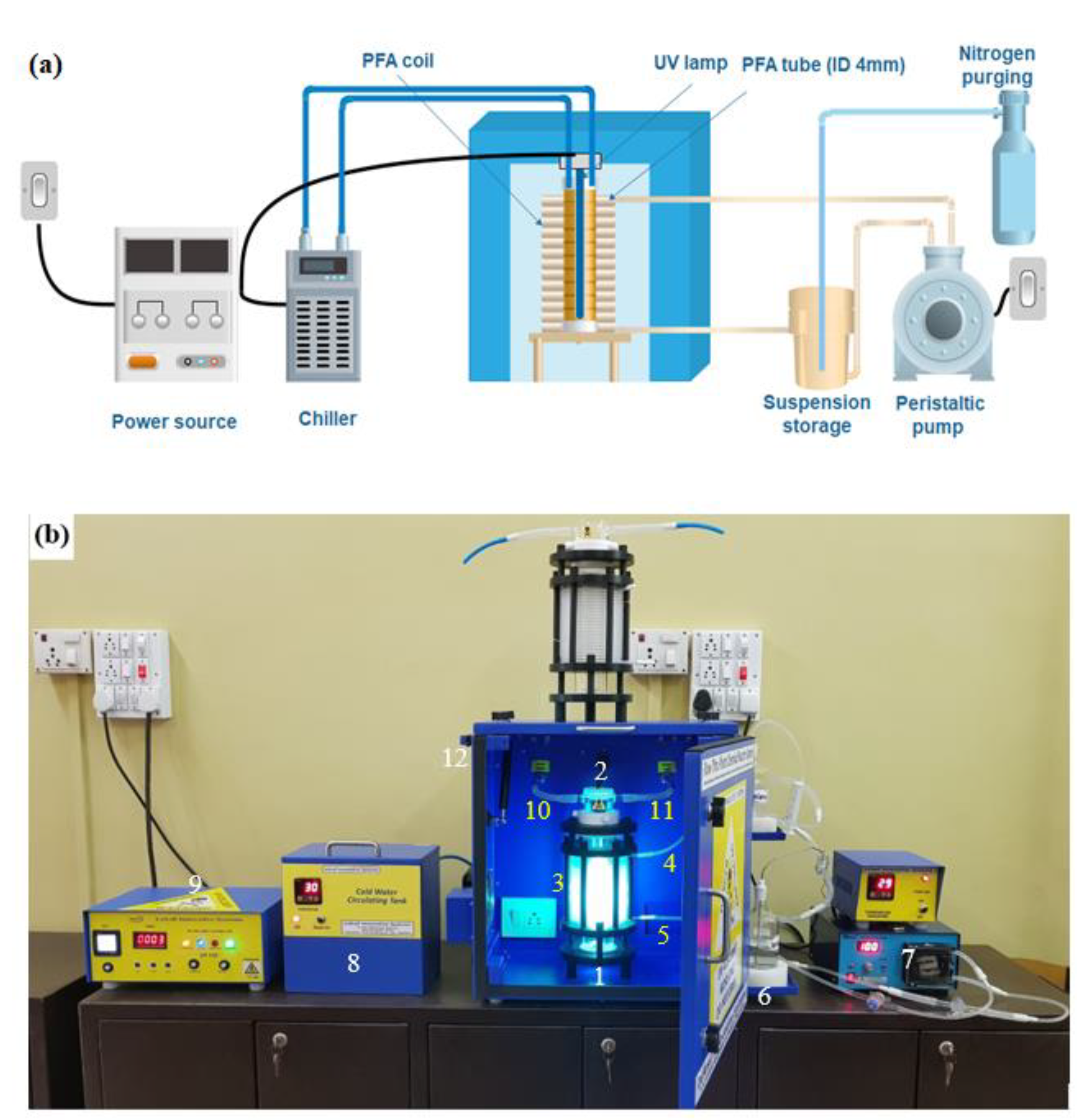
This sub-section gives an outline of the experimental procedure employed in this study. In Section 2.2.1, the coiled tube UV reactor is described, and a description of the emulsion preparation with different PCM to monomer ratios is then outlined in Section 2.2.2. After that, the detailed procedure for the microencapsulation process is presented in Section 2.2.3. Subsequently, in Section 2.3, the produced microcapsules are characterized in terms of particle sizes, thermal characteristics and performance processes, with reference to the microencapsulation conditions.

2.2.1. UV Equipment

A perfluoroalkoxy (PFA) coiled tube (ID: 4 mm) UV reactor was used to perform the polymerization. PFA was chosen due to its higher transmission to UV light, thermal and UV stabilities and smooth surface [38]. Figure 2 shows the schematic diagram and experimental setup of the coiled tube reactor. A medium-pressure mercury lamp was placed inside a cooling jacket made of quartz with circulating cold water. The PFA tube was coiled around the cooling jacket with the help of a plastic stand, and the coiled reactor was placed inside an opaque box to avoid UV hazards. The coiled tube reactor system is manufactured by Lelesil Innovative Systems Ltd. (Thane, Maharashtra, India), and has been previously utilized in a variety of applications [40,41,42]. This study, however, is first time it is employed for the UV microencapsulation of PCMs.

2.2.2. Emulsion Preparation

A standard PCM emulsification procedure was used as described by Ref. [24], with some modifications. Two phases, namely aqueous and organic phases, were prepared separately. For the aqueous phase, surface-active agents (1 g of PVA and 0.056g of SDS approximately) were dissolved in 100 g of distilled water. A mixture of monomer, cross-linking agent, photo-initiator and PCM (called organic phase) was prepared. The organic phase was added to the aqueous phase to emulsify the mixture with a high shear mixer (Silverson L5M-A laboratory mixer) at a stirring rate of 4000 rpm for 10 min at a temperature above the melting point of the PCM, which was 25 °C in this study. Table 1 shows the chemical recipe and ingredients for preparing the PCM microcapsules. The amount of photo-initiator (0.65 g of Irgacure 819) and aqueous phase (255 g) were kept constant for all UV polymerization experiments.

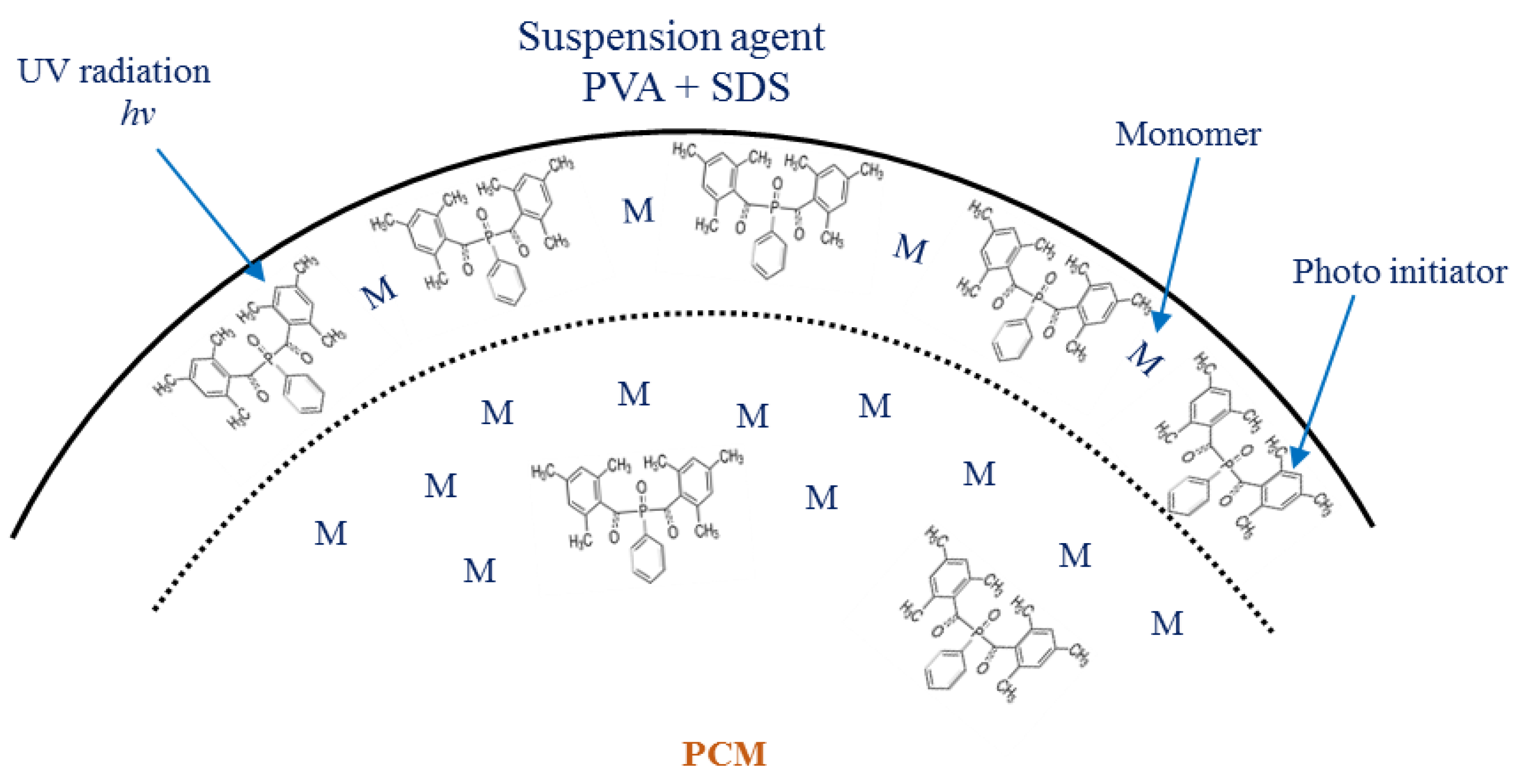
2.2.3. Microencapsulation Procedure

In this work, the photo-polymerization reaction for microencapsulation of PCMs was carried out in a coiled tube UV reactor system. The prepared emulsion was poured into a storage tank and purged with nitrogen gas at 60 bubbles/min during the photo-polymerization reaction. A peristaltic pump was used to recirculate the emulsion from the storage tank to the coiled tube reaction cell at different volumetric flow rates. A medium-pressure mercury lamp having different powers (450 W and 250 W) was placed in the center of the reaction cell to photo-induce the polymerization reaction of MMA. Microencapsulation was carried out to investigate the effects of multiple factors, including emulsion volumetric flow rate, circulation time, different PCM-to-monomer mass ratios and power of the UV lamp. The flow rate before polymerization was measured by passing the emulsion when the lamp was switched to the OFF mode. Table 2 shows the list of different operating conditions used in this study for the microencapsulation of PCMs.
The produced suspension of microcapsules (after the reaction completion) was filtered and placed in an oven to dry, followed by washing with n-hexane solvent to remove any unreacted monomer or non-encapsulated PCM. Prior to testing, the PCM microcapsules were separated from hexane by filter paper and dried at 50 °C for 2 h.

2.3. Characterization of Microcapsules

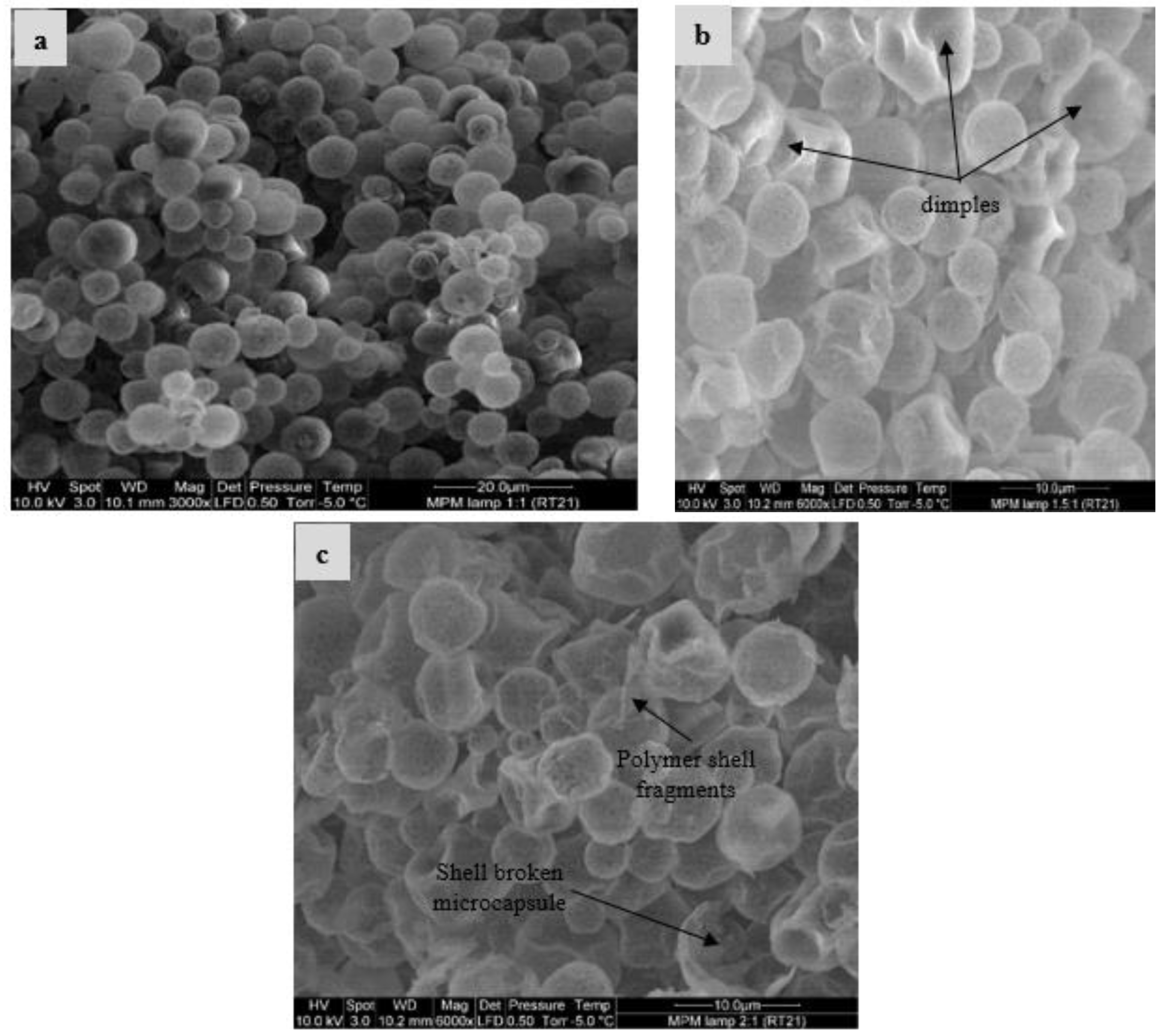
2.3.1. Scanning Electron Microscope

The morphology of microcapsules was observed using a scanning electron microscope (SEM) (Philips XL30S FEG, Amsterdam, The Netherlands). All the microcapsule samples were gold-coated prior to electron microscopy.

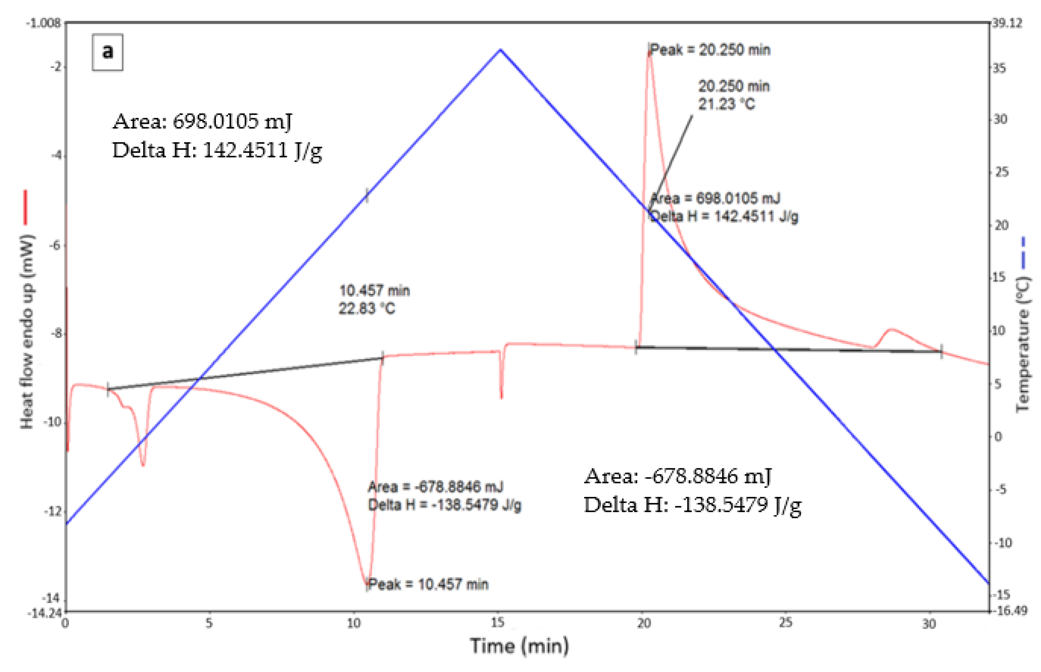
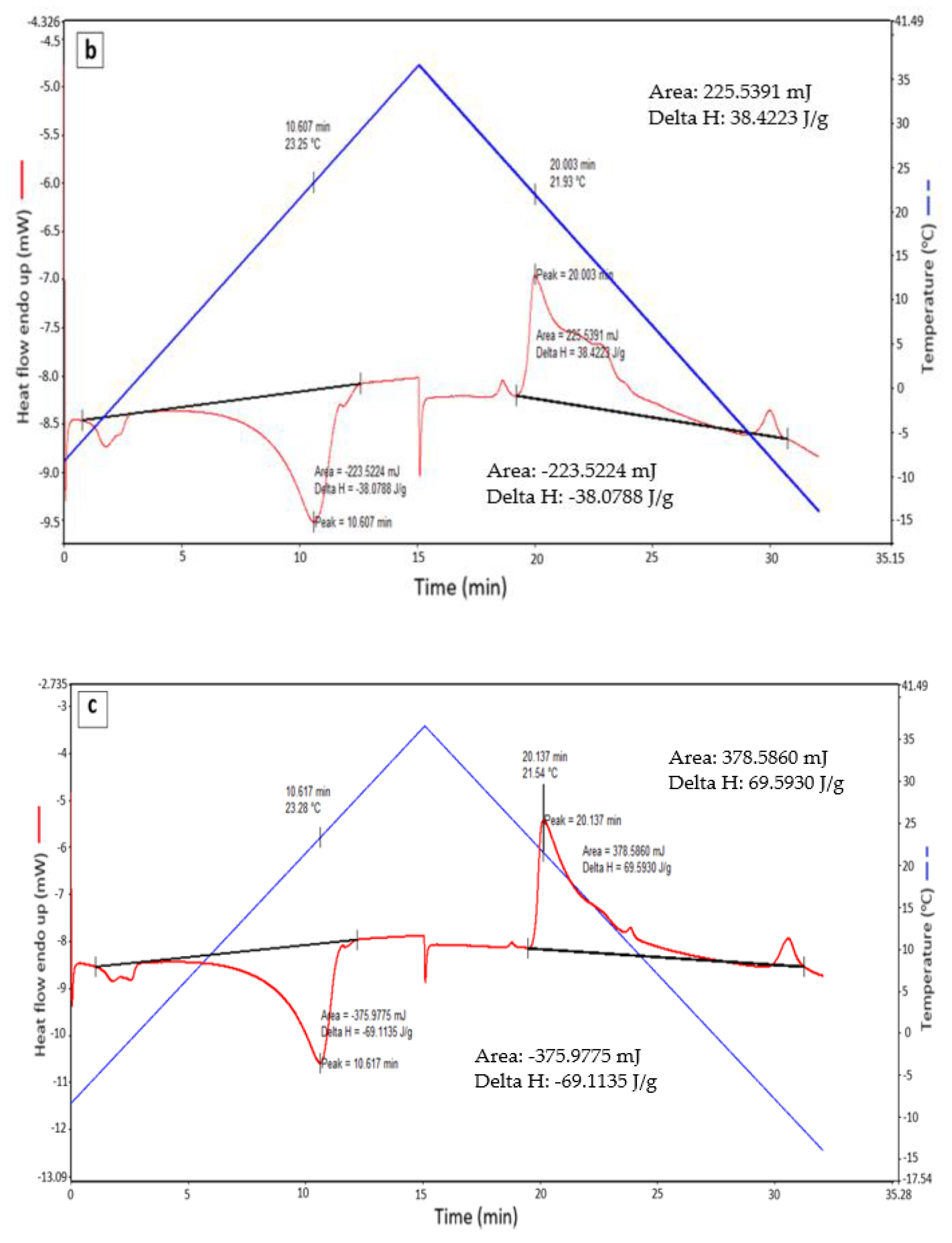
2.3.2. Differential Scanning Calorimetry (DSC)

The obtained microcapsules and bulk PCM were analyzed for melting and solidification temperatures, as well as their phase change enthalpies using a Perkin Elmer differential scanning calorimeter (DSC) 8000. Each sample was cycled from −10 °C to 36 °C and back to −15 °C to measure the melting/solidification enthalpies with a heating/cooling rate of 3 °C/min. The PCM content is defined as the ratio of latent heat of the microcapsules to the latent heat of the pure (non-encapsulated) PCM, as given in Equation (1).
%   PCM   in   microcapsules   by   mass = Δ H Microcapsules Δ H Pure   PCM × 100  
where Δ H Microcapsules is the latent heat of microcapsules (J/g) and Δ H Bulk   PCM is the latent heat of bulk PCM (J/g). In Equation (1), it is assumed that the influence of the shell polymeric layer on the latent heat of the incorporated PCM is negligible.

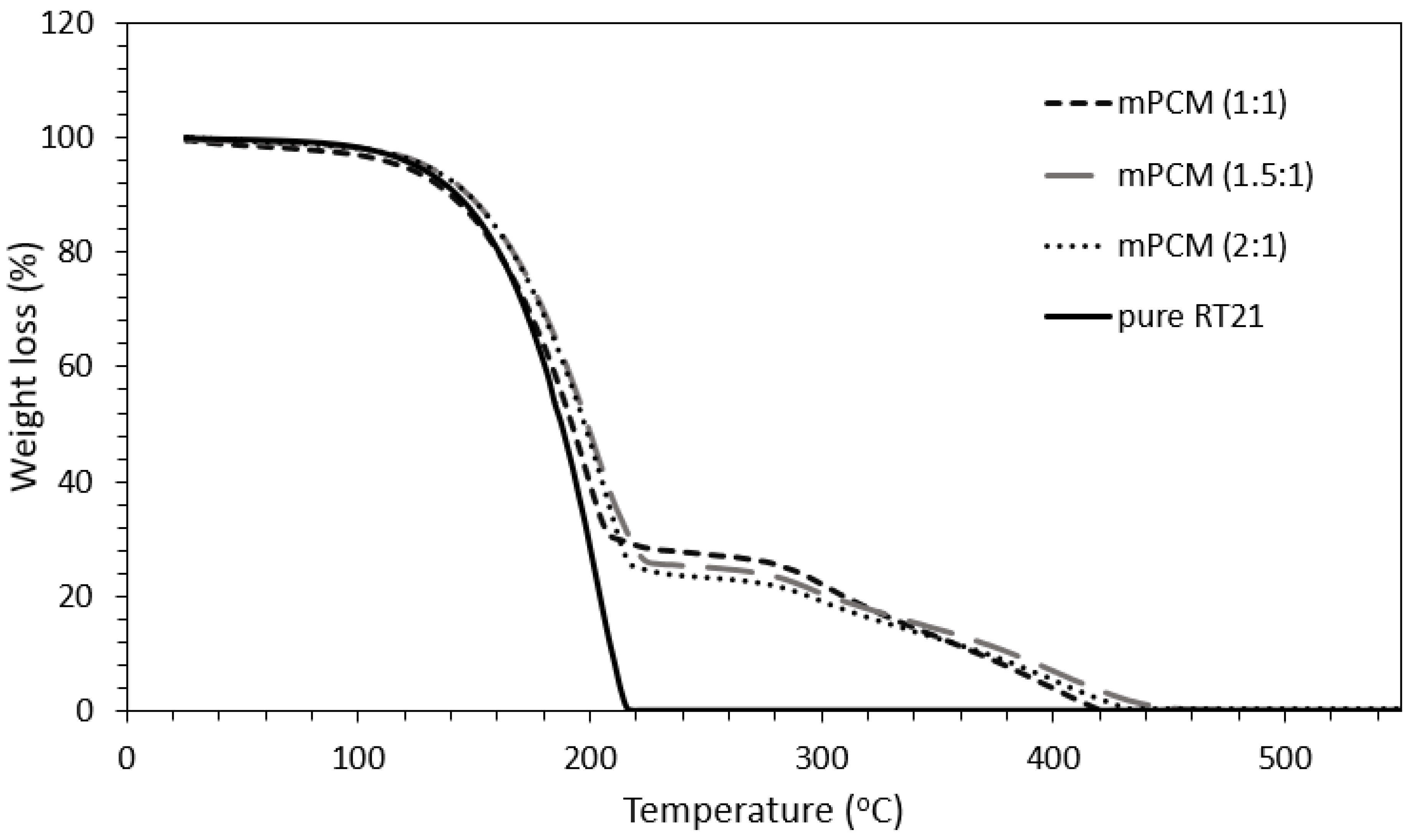
2.3.3. Thermogravimetric Analysis

The fabricated microcapsules were evaluated for their thermal stability by thermogravimetric analysis (TGA). The experiment was carried out on a Shimadzu TGA-50 model thermogravimetric analyzer, Kyoto Japan, under a preconditioned nitrogen atmosphere flowing at 20 mL/min. For each experiment, a sample within the mass of 4–7 mg was introduced in an aluminum pan and subsequently heated from 25 to 550 °C at a heating rate of 10 °C/min.

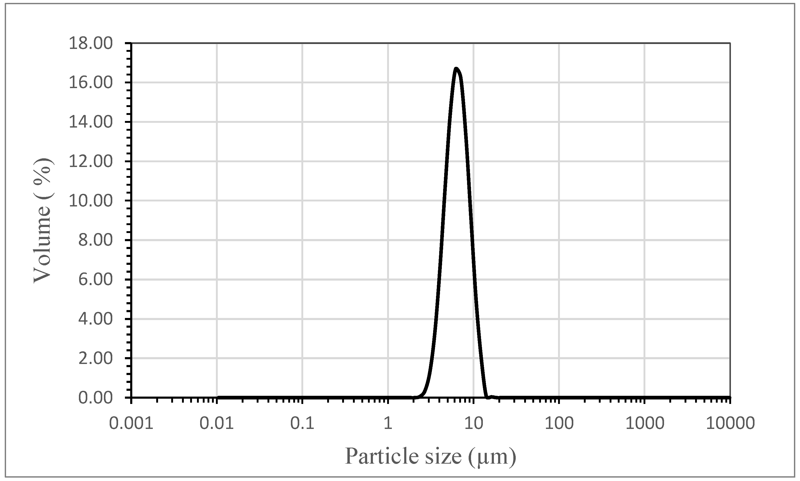
2.3.4. Particle Size and Particle Size Distribution (PSD)

The particle size distribution was measured by using a particle size distribution (PSD) analyzer (Mastersize 2000, Malvern, UK). The instrument works on the principle that a beam of light scatters by suspended particles, and the angle of light scattering is inversely proportional to the particle size. A small sample of the suspended microcapsules was introduced to the PSD unit until the obscuration value of 15–20% was obtained. The ultrasonic probe was used to prevent particle agglomeration and a pump was used to circulate the suspended particles into the measuring cell. Each sample was analyzed three times and the average was taken.

2.3.5. Process Performance

Process performance parameters in terms of encapsulation conditions are important to determine the effectiveness of the microencapsulation. Immediately after the completion of the polymerization process, a small amount of sample was collected from the well-mixed suspension solution and oven dried, then washed with n-hexane solvent to remove any unreacted monomer or non-encapsulated PCM. The PCM microcapsules were then separated carefully from hexane by filtration and dried at 50 °C for 2 h. The mass of the dried powder was recorded, and then the sample was ready for DSC testing.
Based on the DSC results, process performance parameters (including the microencapsulation efficiency, yield of microencapsulation and monomer conversion) were estimated. The microencapsulation efficiency represents the mass ratio of the PCM encapsulated to the initial PCM used (Equation (2)). At the same time, the product yield represents the ratio of the mass of dried powder obtained to the initial mass of monomers, PCM, and crosslinkers used (Equation (3)). The monomer conversion is defined as the amount of monomers polymerized to form the shell divided by the initial amount of monomers. It can help determine the amount of unconverted monomers (Equation (4)).
The microencapsulation efficiency is calculated as follows:
PCM   encapsulation   efficiency   ( % ) = mass   of   encapsualted   PCM   mass   of   PCM   used   × 100  
where:
Mass   of   encapsulated   PCM   ( g )                                                               = The   total   mass   of   collected   dried   powder   ×   %   PCM   in   microcapsules   by   mass   ( DSC )
The microencapsulation yield is calculated as follows:
Yield   ( % ) = mass   of   encapsualted   PCM + mass   of   shell   polymer   The   total   mass   of   PCM   and   monomers   used   × 100  
where:
Mass   of   shell   polymer   ( g ) = The   total   mass   of   collected   dried   powder   × ( 1 %   PCM   in   microcapsules   by   mass   ( DSC ) )
The monomers conversion is calculated as follows:
Monomer   conversion   ( % ) = mass   of   shell   polymer   mass   of   monomers   used   × 100
In the above equations, it is assumed that there are no PCM, monomer or water losses during the encapsulation process, which may not be always true.

3. Results and Discussions

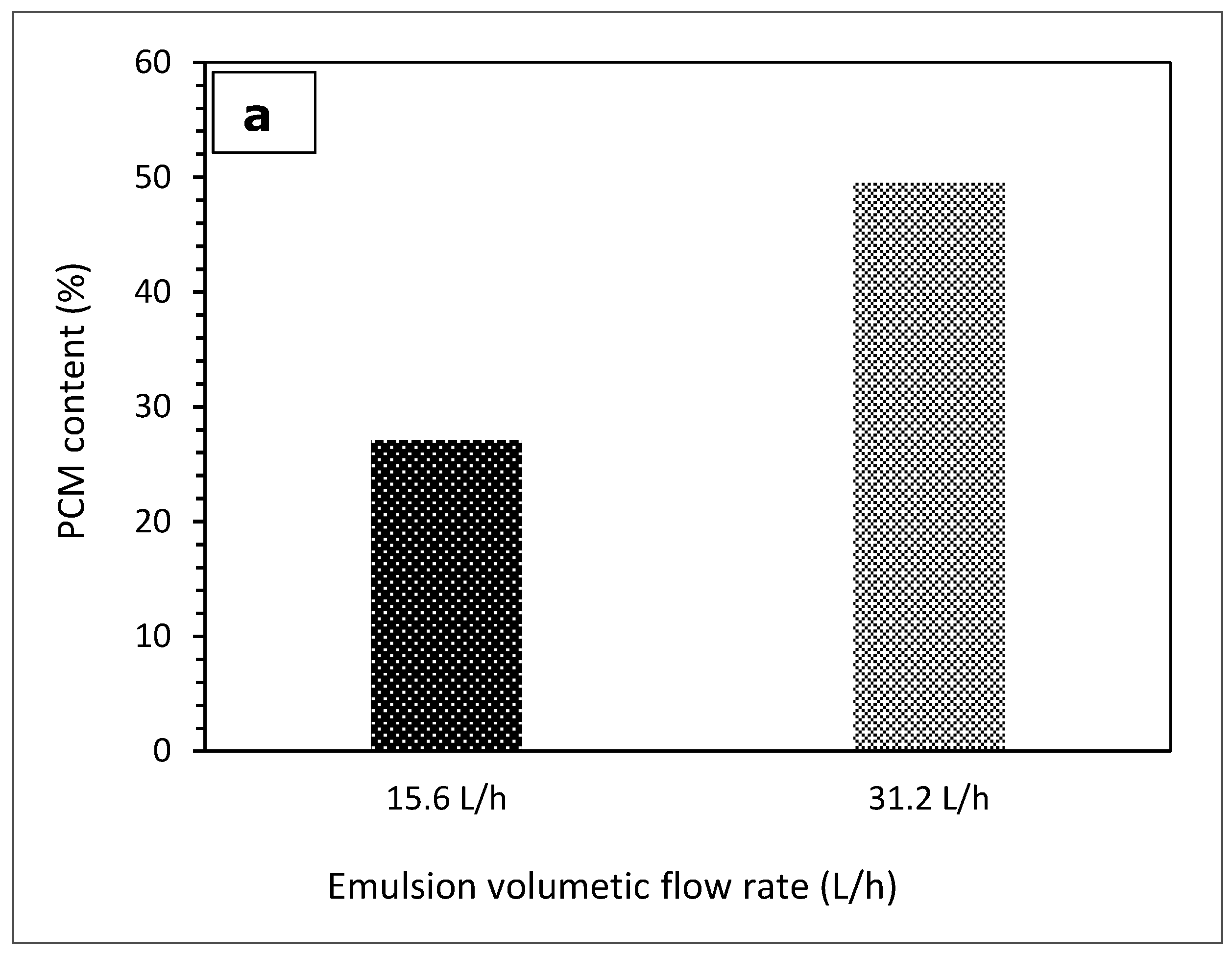
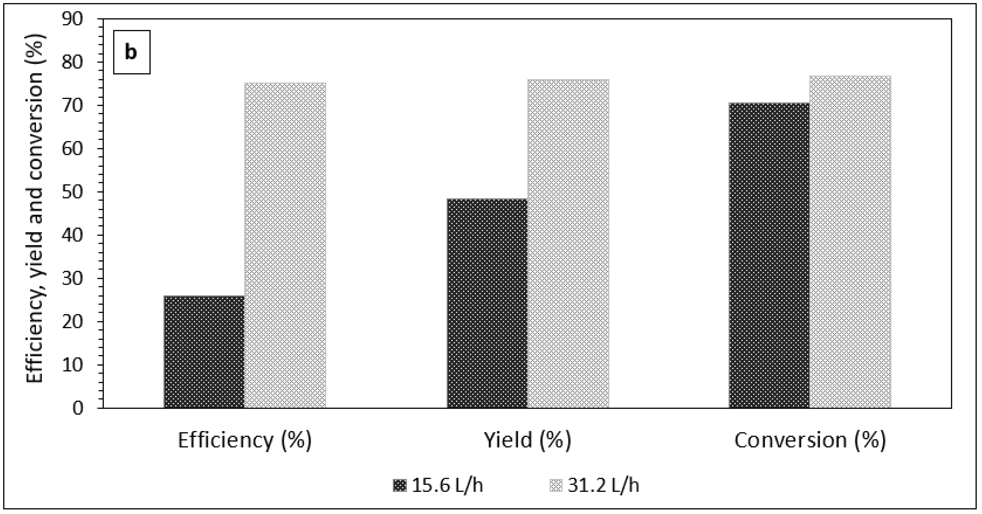
3.1. The Effect of Emulsion Volumetric Flow Rate on the Characteristics of PCM Microcapsules

As UV radiation has limited penetration within opaque liquids, it is crucial to consider its process characteristics, including path length, flow rate, mixing during flow and temperature, during the reaction. The coiled tube reactor with an appropriate oil-soluble photoinitiator provides a better UV exposure to the flowing liquid as it can provide mixing during the flow due to the arising secondary flow (referred to as Dean flow). The experimental setup used in this study can aid better exposure in several ways. Primarily, the coiled shape configuration can improve Dean vortices in the cross-section of the coiled tube (Figure 3), improving the possibility of exposing fresh layers to luminous zones of the tube. Secondly, nitrogen purging at the inlet and outlet also facilitates mixing, giving a fresh emulsion a higher possibility of exposure to UV in subsequent cycles. More so, the peristaltic pump avails an oscillatory fluid motion, which improves UV exposure during treatment [43].
To this end, the effect of two different emulsion volumetric flow rates (15.6 and 31.2 L/h) on the PCM content within the produced microcapsules and process quality parameters, in terms of encapsulation efficiency, product yield and monomer conversion, was investigated, and the result is shown in Figure 4. The mass ratio of PCM to monomers and emulsion circulation time were kept constant at 1:1 and 10 min, respectively. At a higher volumetric flow rate of 31.2 L/h, the PCM content in capsules was 49.53%, whereas it was only 27.12% at the lower volumetric flow rate of 15.6 L/h (Figure 4a). The higher PCM content of the microcapsules was obtained with the higher volumetric flow rate, which creates mixing needed for a better UV exposure. The improvements in other process performance parameters are shown in Figure 4b.
Figure 5 shows the DSC measurements for non-encapsulated PCM and PCM microcapsules as prepared at different volumetric flow rates and a summary of their thermal properties is presented in Table 3. According to the results, the peak melting temperatures of the prepared PCM microcapsules at different flow rates are slightly shifted by about 0.5 °C in comparison with non-encapsulated PCM. The onset solidification temperature for all samples is almost the same. However, the sample with a lower volumetric flow rate shows a wider PCM solidification as shown in Figure 5b, which is probably due to poor heat transfer between the DSC pan and the microcapsules.
The average particle size of PCM microcapsules obtained at 31.2 L/h was found to be 6.5 µm (Figure 6), which is quite close to the one obtained in thermal suspension polymerization in earlier studies [30] since same shear rate was used during preparation of the emulsion. The particle size can be further reduced by improving the operating conditions of emulsification, including the use of high shear homogenization and the use of homogenization followed by ultrasonication. However, very small particle sizes may also induce separation problems. Small microcapsules remain suspended for long time, which makes their separation difficult. Additionally, associated difficulties can appear with their powder handling that require safety considerations. However, smaller emulsion droplet sizes improve UV transmission and shell particle strength [44].

3.2. The Effect of UV Treatment Time on the PCM Microcapsules Proprieties

The effect of different emulsion circulation times (5, 10 and 15 min) was analyzed in order to optimize the microencapsulation process in terms of yield, conversion and efficiency. The reduction in polymerization time can benefit to reduce energy consumption and length of the coil, and thus lower capital/operating costs. Table 4 shows PCM content of the microcapsules and microencapsulation process parameters at different emulsion circulation times. All the PCM microcapsules were prepared with a similar emulsion volumetric flow rate (31.2 L/h), composition and power of the UV lamp (450 W). When increasing emulsion circulation time from 5 to 15 min, the PCM content of the microcapsules increased, as well. A sufficient polymerization time is required in order to optimize microcapsules in terms of PCM content with required shell strength. With 5 min of circulation time, PCM content of the microcapsules was lower as the shell strength was not strong enough to hold PCM, while with 10 min, shell thickness was higher to contain the PCM and resulted in higher PCM per unit mass (Table 4). The PCM content after 10 min was only slightly less than that obtained after 15 min. However, the PCM microencapsulation efficiency, yield and monomer conversion were higher, and thus more beneficial. Therefore, 10 min emulsion circulation time will be chosen for further investigations.

3.3. The Effect of Different PCM-to-Monomer Mass Ratios on the PCM Microcapsules Proprieties

The effect of different PCM-to-monomer mass ratios were analyzed to optimize the PCM content of microcapsules. At present, the cost of PCM is higher than that of the polymer used to make the shell, making it necessary to minimize PCM losses during microencapsulation. On the other hand, the energy density of the microcapsules is important in most thermal energy storage applications. Thus, different mass ratios of PCMs to monomers were tested, including 1:1, 1.5:1 and 2:1. The highest yield was obtained using a mass ratio of 1:1, which then decreased when increasing the mass ratio. However, the highest PCM content was observed for the mass ratio of 1.5:1, and slightly decreased with the mass ratio of 2:1 (Table 5). This might be due to multiple reasons, including the lower shell thickness, weaker shell or broken shells obtained with the mass ratio of 2:1. These could have resulted in lower PCM content as PCMs might have been lost during the washing step with n-hexane, thus resulting in lower PCM contents.
Figure 7 shows SEM images of PCM microcapsules prepared at different mass ratios of PCM-to-monomers as observed using a Philips XL30S FEG SEM machine, The Netherlands. Spherical, smooth and compact surfaces of PCM microcapsules were obtained when the mass ratio of PCMs to monomers was 1:1 (Figure 7a). However, dimples and rough microcapsule surfaces were observed as the PCM content increased, as shown in Figure 7b,c. Furthermore, some microcapsules with broken shells were found when using a mass ratio of 2:1 (Figure 7c). This confirms the low PCM content observations reported in Table 5.

3.4. The Effect of UV Lamp Power on the PCM Microcapsule Characteristics

The power of the UV lamp could be an important factor that affects the characteristics of the produced microcapsules. In thermal encapsulation, low temperature followed by high temperature is suitable to achieve good quality capsules [21]. The direct exposure of the suspension to a high temperature can affect shell morphology and may result in low PCM retention in the microcapsules. In this study, two UV lamps with different powers (250 W and 450 W) were utilized separately at the optimized conditions to analyze the effect of UV lamp power on the performance parameters of the microencapsulation process, and the result is presented in Table 6. With the 250 W lamp, the PCM content in microcapsules was 66.54%. However, when using the 450 W with similar conditions, it was 60.97%. This could be due to different UV intensities in these two lamps. Better results were obtained with the 250 W lamp while considering the process characteristics, including yield, efficiency and conversion. This can be explained as the UV lamp of higher intensity (450 W) interacts with monomer, fast polymerization with a higher local heating forms an opaque crest around the organic droplet. This will quickly stop the UV penetration into the deeper layer of the polymeric shell. On the other hand, a UV lamp of low intensity (250 W) will allow longer time for a deeper UV penetration as it takes more time to make the crest opaque. Additionally, a 450 W UV lamp often results in higher temperature generation than a 250 W UV lamp, thereby reducing the UV lamp’s efficiency at higher temperatures.

3.5. Thermal Stability

Thermal stability is an important feature in assessing the performance of PCM microcapsules in buildings when used as a thermal buffer. As such, information regarding the thermal degradation behavior of the developed microcapsules under rapid heating is important. The TGA results of PCM microcapsule specimens synthesized with different PCM-to-monomer ratios in comparison to pure PCM is shown in Figure 8. The weights of the TGA samples were originally within the range of 4 to 7 mg. Previous studies show that only a slight variation may exist in the thermal performance results when there is a slight variation in the weight of samples being tested [45]. The choice of a low heating rate of 10 °C/min was to minimizes the temperature gradient within the microcapsules during the thermal degradation process. It is also worth noting that higher heating rates may affect polymer decomposition by impacting the relative rates of competing decomposition reactions [46].
Clearly, the pure RT21 PCM experienced a single-step mass loss due to PCM evaporation. As there was no shell to resist thermal effect, the PCM lost its weight rapidly until a maximum weight loss of 99.2% occurred at ~220 °C. The remaining 0.8% represents a negligible amount of carbon residue in the pan. In contrast, the TGA graphs of all the microcapsules tested exhibited a two-step thermal degradation process with a much slower mass loss rate compared to the pure PCM.
The first degradation step of the microcapsules depicts the PCM mass loss from the capsules due to the impact of heat. A closer look at Figure 8 shows that sample with the PCM to monomer ratio of 1:1 was the first to complete its first step of thermal degradation, followed by that with the ratio of 2:1 and lastly the one with the ratio of 1.5:1. The TGA plots confirm the results presented in Table 5, which show that sample with the PCM to monomer ratio of 1.5:1 had a slightly higher percentage of PCM content (of ~61%) than that with the ratio of 2:1 (of only 57.8%). This type of analogous result in the percentage content of PCM retained in the microcapsules is also reflected in their calculated mass losses (Figure 8). The sample with the ratio of 1:1 experienced a weight loss lower than those obtained for the remaining samples. Therefore, the weight loss was most likely due to evaporation of PCM.
On the other hand, the second degradation step of the encapsulated PCMs corresponds to the degradation of the shell material. As a result, it is indicative of an increasing shell beginning from the sample with the ratio of 2:1 to the sample with the ratio of 1:1. The weight losses for the samples with the ratios of 1:1, 1.5:1 and 2:1 were 67.6%, 72.7% and 73.5%, respectively. The result also confirms the fact that the sample with the PCM to monomer ratio of 1:1 had a thicker shell wall owing to the lower PCM content compared to other formulations. The polymer shells degradation occurred in the range of 320–450 °C, suggesting that the microencapsulated PCM samples are more thermally stable than the pure PCM.
The findings from this work were compared with previous research employing the use of UV irradiation in the polymerization of PCM microcapsules as illustrated in Table 7. In all the studies reported, the lowest microencapsulation time was 30 min and the least temperature achieved during the microencapsulation process was 45 °C, which may be too high for some heat-sensitive PCMs. The current study has overcome this limitation by adopting a unique technique to produce capsules with up to 85.8% microencapsulation efficiency, achieved in only about 10 min at a microencapsulation temperature of no more than 30 °C.

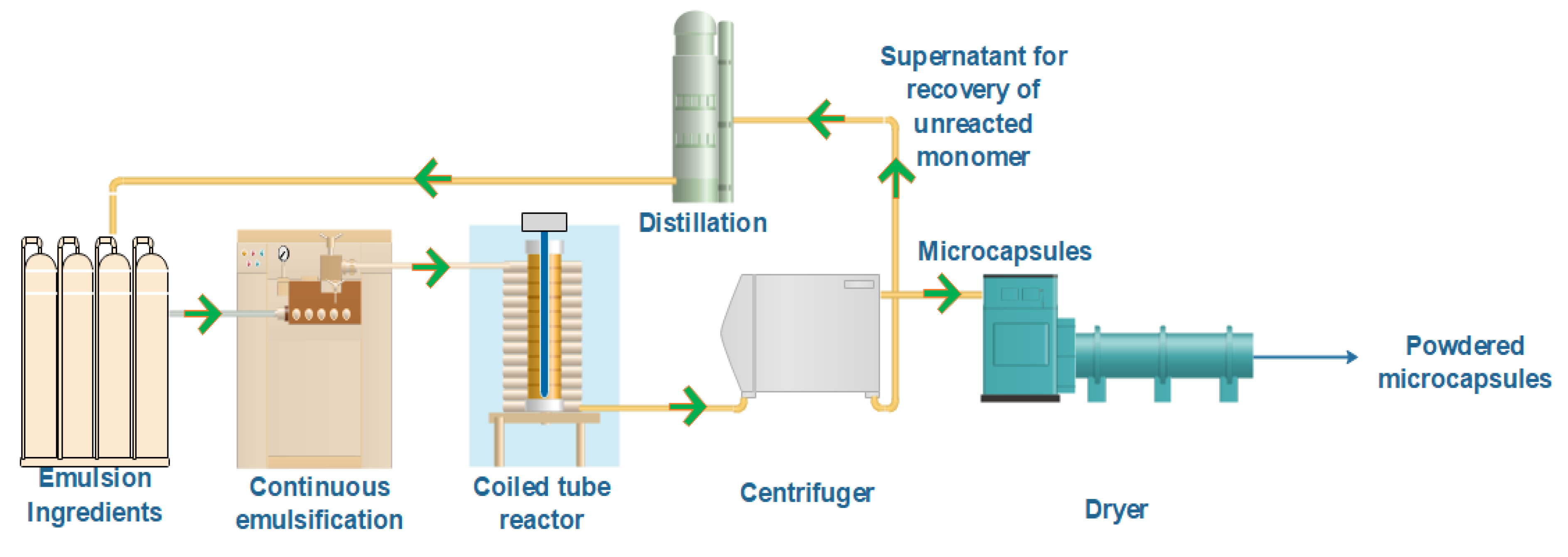
3.6. A Possibility of Continuous Microencapsulation Using Coiled Tube Reactor

The conventional thermal PCM encapsulation process requires a long time for polymerization, usually up to 6 h. On the other hand, the UV microencapsulation using a coiled tube reactor can be achieved in a short period, which saves energy consumption considerably, thus providing flexibility to be integrated in a continuous process. According to the present study, only about 10 min is required at ambient conditions for the emulsion polymerization process when a UV lamp power of 250 W is employed, which is considered a faster, cost-effective and more efficient process. In terms of its commercialization, multiple factors need consideration, including:
  • Cleaning process of PFA tubing;
  • Integration of coiled tube reactor into a continuous process; and
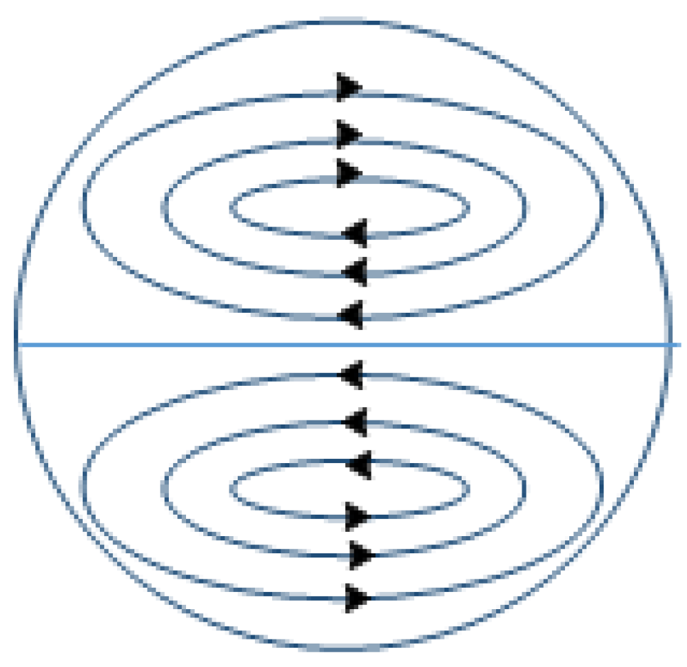
  • Mixing during UV treatment.
Cleaning the interior of the PFA tubing will be the biggest challenge because microcapsules or polymerized monomers may deposit on the inner side of the tube. Without adequate flushing, these deposits may clog the tubes, prevent proper emulsion flow and reduce UV penetration. Due to the coil-shaped geometry, some effort may be required to clean the tube after polymerization. There are commercially available systems, such as the StoneAge® Navigator, which utilize a circular motion that allows for the cleaning of narrow tubing.
A possible integration scheme of the coiled tube UV reactor into a continuous system for PCM microencapsulation is illustrated in Figure 9. The first step involves the emulsification of components fed in the right proportions and at the appropriate emulsifying conditions. This is followed by the introduction of the emulsified suspension into the UV reactor for polymerization. After polymerization, the wet microcapsule powders are separated from the supernatant by centrifugation. The collected wet PCM microcapsules are then passed through a dryer to obtain dried microcapsules, while the supernatant may undergo a distillation process to recover the unreacted monomers.
There are some concerns in the continuous polymerization process with a coiled tube UV reactor. The first concern is the increasing viscosity of the suspension as the polymerization proceeds, which changes the flow characteristics and exposure to UV radiation during treatment. A second concern is that adequate mixing of the suspension is required during the polymerization process to expose the untreated suspension and improve uniformity.
The aforementioned issues may be addressed in the following ways: firstly, adopting a variable flow rate (rather than a constant flow rate), with an incremental variation in the flow rate to maintain similar flow patterns, may be used to overcome the increasing viscosity problem. For a proper exposure of the untreated suspension, reversing the vortex direction after some time or introducing mixing channels at specific lengths of the PFA coils is suggested. In this study, mixing was obtained by multiple passes through the coiled tube and by nitrogen purging. It is worth mentioning that the length of the tube depends on the treatment time required. Additionally, LED UV lamps produce a very narrow spectrum of UV wavelengths, resulting in less energy wasted as heat. Hence, further reduction in reaction time and energy consumption is possible in this process when using energy-efficient LED UV lamps that can target the photoinitiator decomposition wavelength more precisely.

4. Conclusions

Microencapsulation of PCMs is one of the best known, most effective and highly efficient methods of containing PCMs in building materials and other commercial applications without the risk of leakage. This study presented a novel approach of utilizing a coiled tube UV reactor for PCM microencapsulation for various applications. It was found that the required polymerization time can be reduced considerably in comparison with the conventional thermal encapsulation methods. Furthermore, unlike the conventional thermal approach, this novel approach enables the encapsulation of PCMs at ambient conditions, which facilitates producing microcapsules of heat-sensitive PCMs with an encapsulation efficiency of up to 86%.
Through this study, the volumetric flow rate of the feed emulsion, the UV lamp power, appropriate mixing and the use of a suitable photoinitiator were essential parameters in the UV polymerization process. With the use of an appropriate organic-soluble photoinitiator (Irgacure 918), the optimum encapsulation yield, conversion, encapsulation efficiency and PCM content were obtained after only 10 min of polymerization. This study revealed that a higher flow rate of emulsion (of 31.2 L/h) provides a better PCM encapsulation in terms of both PCM content and encapsulation efficiency. In addition, an increase in the PCM-to-monomer mass ratio up to 2:1 led to a corresponding increase in the latent heat of microencapsulated PCMs, but it impacted the anticipated spherical shape of the microcapsules. The results demonstrate the applicability of low UV lamp power of 250 W to achieve improved monomer polymerization, especially for encapsulating heat-sensitive PCMs.
Overall, the novel approach of PCM microencapsulation using a coiled tube UV reactor is an effective way to overcome the drawbacks associated with the conventional thermal approach, which are mainly the long time and high temperature required. Thus, the new method holds potential for adaptation in the rapid, continuous and industrial-scale production of PCM microcapsules with less energy consumption and lower capital cost requirements. Furthermore, it can be employed for encapsulating heat-sensitive PCMs, widening their scope of application.

Author Contributions

J.A.A., R.A.-S. and M.M.F. planned and designed the study. J.A.A., R.A.-S. and C.A.I. wrote the first draft. R.A.-S., C.A.I., S.A.A.-M., J.K. and M.M.F. improved the manuscript and contributed to the result interpretation. S.A.A.-M., J.K. and M.M.F. supervised the work. All authors discussed the results, commented on the manuscript. All authors have read and agreed to the published version of the manuscript.

Funding

This project in which this work was conducted was funded by Qatar Foundation, Qatar (TDF1-0611-170037).

Institutional Review Board Statement

Not applicable.

Informed Consent Statement

Not applicable.

Data Availability Statement

Not applicable.

Acknowledgments

This publication was made possible by the Industry Development and Knowledge Transfer (IDKT) award (Project # TDF1-0611-170037). IDKT is a division of Qatar Foundation Research, Development and Innovation (QF RDI). The statements made herein are solely the responsibility of the authors.

Conflicts of Interest

The authors declare no conflict of interest.

Nomenclature

PCMphase change materialTpmpeak melting temperature (°C)
mPCMmicroencapsulated phase change materialTpfpeak freezing temperature (°C)
TESthermal energy storage Δ H mmelting enthalpy (kJ/kg)
PFAperfluoroalkoxy Δ H f freezing enthalpy (kJ/kg)
PVApolyvinyl alcohol Δ H ave average enthalpies of melting and freezing (kJ/kg)
EGDMethylene glycol dimethacrylateppmpart per million
MMAmethyl methacrylateIDinternal diameter (mm)
PMMApoly-methyl-methacrylateµmmicrometer
RTRubitherm PCM rpmrevolution per minute
SDSsodium dodecyl sulfateminminute
Mwmolecular weightWwatt
DSCdifferential scanning calorimetryL/hliter/hour
TGAthermo-gravimetric analysisVFvolumetric flowrate (L/h)
SEMscanning electron microscopeUVultraviolet
PSDparticle size distribution

References

  1. Marin, P.; Saffari, M.; de Gracia, A.; Zhu, X.; Farid, M.; Cabeza, L.F.; Ushak, S. Energy savings due to the use of PCM for relocatable lightweight buildings passive heating and cooling in different weather conditions. Energy Build. 2016, 129, 274–283. [Google Scholar] [CrossRef] [Green Version]
  2. WGBC. Bringing Embodied Carbon Upfront: Coordinated Action for the Building and Construction Sector to Tackle Embodied Carbon; World Green Building Council: London, UK, 2019. [Google Scholar]
  3. Ikutegbe, C.A.; Farid, M.M. Application of phase change material foam composites in the built environment: A critical review. Renew. Sustain. Energy Rev. 2020, 131, 110008. [Google Scholar] [CrossRef]
  4. Schmerse, E.; Ikutegbe, C.A.; Auckaili, A.; Farid, M.M. Using PCM in Two Proposed Residential Buildings in Christchurch, New Zealand. Energies 2020, 13, 6025. [Google Scholar] [CrossRef]
  5. Kosny, J. PCM-Enhanced Building Components: An Application of Phase Change Materials in Building Envelopes and Internal Structures; Springer: Berlin/Heidelberg, Germany, 2015. [Google Scholar]
  6. Cabeza, L.F.; Castellón, C.; Nogués, M.; Medrano, M.; Leppers, R.; Zubillaga, O. Use of microencapsulated PCM in concrete walls for energy savings. Energy Build. 2007, 39, 113–119. [Google Scholar] [CrossRef]
  7. Liu, T.; Liu, Y.; Yang, L.; Liu, J.; Qiao, Y.; Yan, D. Impacts of PCM Location and Thickness on Dynamic Thermal Characteristics of External Walls for Residential Buildings. In Modelling Environmental Dynamics; Springer: Singapore, 2020; pp. 127–135. [Google Scholar]
  8. Koschenz, M.; Lehmann, B. Development of a thermally activated ceiling panel with PCM for application in lightweight and retrofitted buildings. Energy Build. 2004, 36, 567–578. [Google Scholar] [CrossRef]
  9. Barzin, R.; Chen, J.J.; Young, B.R.; Farid, M. Application of PCM underfloor heating in combination with PCM wallboards for space heating using price based control system. Appl. Energy 2015, 148, 39–48. [Google Scholar] [CrossRef]
  10. Cabeza, L.F.; Castell, A.; Barreneche, C.D.; De Gracia, A.; Fernández, A.I. Materials used as PCM in thermal energy storage in buildings: A review. Renew. Sustain. Energy Rev. 2011, 15, 1675–1695. [Google Scholar] [CrossRef]
  11. Khudhair, A.M.; Farid, M.M. A review on energy conservation in building applications with thermal storage by latent heat using phase change materials. Energy Convers. Manag. 2004, 45, 263–275. [Google Scholar] [CrossRef]
  12. Pomianowski, M.; Heiselberg, P.; Zhang, Y. Review of thermal energy storage technologies based on PCM application in buildings. Energy Build. 2013, 67, 56–69. [Google Scholar] [CrossRef]
  13. Soares, N.; Costa, J.J.; Gaspar, A.R.; Santos, P. Review of passive PCM latent heat thermal energy storage systems towards buildings’ energy efficiency. Energy Build. 2013, 59, 82–103. [Google Scholar] [CrossRef]
  14. Salaün, F. Phase Change Materials for Textile Application, Textile Industry and Environment; IntechOpen: London, UK, 2019. [Google Scholar] [CrossRef] [Green Version]
  15. Gin, B.; Farid, M. The use of PCM panels to improve storage condition of frozen food. J. Food Eng. 2010, 100, 372–376. [Google Scholar] [CrossRef]
  16. Shukla, A.; Sharma, A.; Shukla, M.; Chen, C.R. Development of thermal energy storage materials for biomedical applications. J. Med Eng. Technol. 2015, 39, 363–368. [Google Scholar] [CrossRef]
  17. Barzin, R.; Chen, J.J.; Young, B.R.; Farid, M.M. Application of weather forecast in conjunction with price-based method for PCM solar passive buildings—An experimental study. Appl. Energy 2015, 163, 9–18. [Google Scholar] [CrossRef]
  18. Al-Shannaq, R.; Young, B.; Farid, M. Cold energy storage in a packed bed of novel graphite/PCM composite spheres. Energy 2019, 171, 296–305. [Google Scholar] [CrossRef]
  19. Roberts, N.S.; Al-Shannaq, R.; Kurdi, J.; Al-Muhtaseb, S.A.; Farid, M.M. Efficacy of using slurry of metal-coated microencapsulated PCM for cooling in a micro-channel heat exchanger. Appl. Therm. Eng. 2017, 122, 11–18. [Google Scholar] [CrossRef]
  20. Jaguemont, J.; Omar, N.; Van den Bossche, P.; Mierlo, J. Phase-change materials (PCM) for automotive applications: A review. Appl. Therm. Eng. 2018, 132, 308–320. [Google Scholar] [CrossRef]
  21. Al Shannaq, R.; Farid, M. Microencapsulation of phase change materials (PCMs) for thermal energy storage systems. In Advances in Thermal Energy Storage Systems; Elsevier: Amsterdam, The Netherlands, 2015; pp. 247–284. [Google Scholar]
  22. Jamekhorshid, A.; Sadrameli, S.M.; Farid, M. A review of microencapsulation methods of phase change materials (PCMs) as a thermal energy storage (TES) medium. Renew. Sustain. Energy Rev. 2014, 31, 531–542. [Google Scholar] [CrossRef]
  23. Tyagi, V.; Kaushik, S.; Tyagi, S.; Akiyama, T. Development of phase change materials based microencapsulated technology for buildings: A review. Renew. Sustain. Energy Rev. 2011, 15, 1373–1391. [Google Scholar] [CrossRef]
  24. Sánchez, L.; Sánchez, P.; de Lucas, A.; Carmona, M.; Rodríguez, J.F. Microencapsulation of PCMs with a polystyrene shell. Colloid Polym. Sci. 2007, 285, 1377–1385. [Google Scholar] [CrossRef]
  25. Ma, S.; Song, G.; Li, W.; Fan, P.; Tang, G. UV irradiation-initiated MMA polymerization to prepare microcapsules containing phase change paraffin. Sol. Energy Mater. Sol. Cells 2010, 94, 1643–1647. [Google Scholar] [CrossRef]
  26. Zhang, H.; Wang, X.; Wu, D. Silica encapsulation of n-octadecane via sol–gel process: A novel microencapsulated phase-change material with enhanced thermal conductivity and performance. J. Colloid Interface Sci. 2010, 343, 246–255. [Google Scholar] [CrossRef]
  27. Sánchez-Silva, L.; Rodríguez, J.F.; Romero, A.; Borreguero, A.M.; Carmona, M.; Sánchez, P. Microencapsulation of PCMs with a styrene-methyl methacrylate copolymer shell by suspension-like polymerisation. Chem. Eng. J. 2010, 157, 216–222. [Google Scholar] [CrossRef]
  28. Borreguero, A.M.; Valverde, J.L.; Rodriguez, J.F.; Barber, A.; Cubillo, J.; Carmona, M. Synthesis and characterization of microcapsules containing Rubitherm®RT27 obtained by spray drying. Chem. Eng. J. 2011, 166, 384–390. [Google Scholar] [CrossRef]
  29. Aydın, A.A. In situ preparation and characterization of encapsulated high-chain fatty acid ester-based phase change material (PCM) in poly(urethane-urea) by using amino alcohol. Chem. Eng. J. 2013, 231, 477–483. [Google Scholar] [CrossRef]
  30. Al-Shannaq, R.; Farid, M.; Al-Muhtaseb, S.; Kurdi, J. Emulsion stability and cross-linking of PMMA microcapsules containing phase change materials. Sol. Energy Mater. Sol. Cells 2015, 132, 311–318. [Google Scholar] [CrossRef]
  31. Al-Shannaq, R.; Kurdi, J.; Al-Muhtaseb, S.; Dickinson, M.; Farid, M. Supercooling elimination of phase change materials (PCMs) microcapsules. Energy 2015, 87, 654–662. [Google Scholar] [CrossRef]
  32. Giro-Paloma, J.; Al-Shannaq, R.; Fernandez, A.I.; Farid, M.M. Preparation and Characterization of Microencapsulated Phase Change Materials for Use in Building Applications. Materials 2015, 9, 11. [Google Scholar] [CrossRef] [Green Version]
  33. Wang, H.; Li, Y.; Zhao, L.; Shi, X.; Song, G.; Tang, G. A facile approach to synthesize microencapsulated phase change materials embedded with silver nanoparicle for both thermal energy storage and antimicrobial purpose. Energy 2018, 158, 1052–1059. [Google Scholar] [CrossRef]
  34. Wang, H.; Zhao, L.; Chen, L.; Song, G.; Tang, G. Facile and low energy consumption synthesis of microencapsulated phase change materials with hybrid shell for thermal energy storage. J. Phys. Chem. Solids 2017, 111, 207–213. [Google Scholar] [CrossRef]
  35. Wang, Y.; Shi, H.; Xia, T.D.; Zhang, T.; Feng, H.X. Fabrication and performances of microencapsulated paraffin composites with polymethylmethacrylate shell based on ultraviolet irradiation-initiated. Mater. Chem. Phys. 2012, 135, 181–187. [Google Scholar] [CrossRef]
  36. Zhang, T.; Chen, M.; Zhang, Y.; Wang, Y. Microencapsulation of stearic acid with polymethylmethacrylate using iron (III) chloride as photo-initiator for thermal energy storage. Chin. J. Chem. Eng. 2017, 25, 1524–1532. [Google Scholar] [CrossRef]
  37. Farid, M.; Al-Shannaq, R.; Al-Muhtaseb, S.; Kurdi, J. Method for Low Temperature Microencapsulation of Phase Change Materials. U.S. Patent 10,913,882 B2, 9 February 2021. [Google Scholar]
  38. Shen, C.; Shang, M.; Zhang, H.; Su, Y. A UV—LEDs based photomicroreactor for mechanistic insights and kinetic studies in the norbornadiene photoisomerization. AIChE J. 2020, 66, e16841. [Google Scholar] [CrossRef]
  39. Dean, W., XVI. Note on the motion of fluid in a curved pipe. Lond. Edinb. Dublin Philos. Mag. J. Sci. 1927, 4, 208–223. [Google Scholar] [CrossRef]
  40. Choudhary, R.; Bandla, S.; Watson, D.G.; Haddock, J.; Abughazaleh, A.; Bhattacharya, B. Performance of coiled tube ultraviolet reactors to inactivate Escherichia coli W1485 and Bacillus cereus endospores in raw cow milk and commercially processed skimmed cow milk. J. Food Eng. 2011, 107, 14–20. [Google Scholar] [CrossRef] [Green Version]
  41. Gautam, D.; Umagiliyage, A.L.; Dhital, R.; Joshi, P.; Watson, D.G.; Fisher, D.J.; Choudhary, R. Nonthermal pasteurization of tender coconut water using a continuous flow coiled UV reactor. LWT 2017, 83, 127–131. [Google Scholar] [CrossRef]
  42. Koutchma, T.; Parisi, B.; Patazca, E. Validation of UV coiled tube reactor for fresh juices. J. Environ. Eng. Sci. 2007, 6, 319–328. [Google Scholar] [CrossRef]
  43. McDonough, J.; Murta, S.; Law, R.; Harvey, A. Oscillatory fluid motion unlocks plug flow operation in helical tube reactors at lower Reynolds numbers (Re ≤ 10). Chem. Eng. J. 2019, 358, 643–657. [Google Scholar] [CrossRef] [Green Version]
  44. Spasic, A.M. Chapter 1—Introduction. In Interface Science and Technology; Elsevier: Amsterdam, The Netherlands, 2018; Volume 22, pp. 1–25. [Google Scholar]
  45. Abu-Bakar, A.S.; Moinuddin, K.A.M. Effects of Variation in Heating Rate, Sample Mass and Nitrogen Flow on Chemical Kinetics for Pyrolysis. In Proceedings of the 18th Australasian Fluid Mechanics Conference, Launceston, Australia, 3–7 December 2012. [Google Scholar]
  46. Erickson, K.L. Application of Low-Heating Rate TGA Results to Hazard Analyses Involving High-Heating Rates; Sandia National Lab.: Albuquerque, NM, USA, 2008. [Google Scholar]
  47. Alkan, C.; Sarı, A.; Karaipekli, A. Preparation, thermal properties and thermal reliability of microencapsulated n-eicosane as novel phase change material for thermal energy storage. Energy Convers. Manag. 2011, 52, 687–692. [Google Scholar] [CrossRef]
  48. Gu, M.; Zhang, W.; Hao, S.; Liu, X.; Zhang, Z.; Shao, F. Ultraviolet light-initiated preparation of phase change material microcapsules and its infrared imaging effect on fabric. Pigment. Resin Technol. 2021, 50, 129–135. [Google Scholar] [CrossRef]
Figure 1. Schematic representation of microencapsulation of PCMs using UV radiation (PVA: polyvinyl alcohol, SDS: sodium dodecyl sulfate, M: monomer).
Energies 14 07867 g001
Figure 2. (a) Schematic diagram and (b) experimental set-up of UV coiled tube reactor: (1) UV reaction cell, (2) UV lamp, (3) coiled PFA tube (ID: 4 mm), (4) inlet emulsion to the UV reaction cell, (5) outlet emulsion from the UV reaction cell, (6) circulation storage tank, (7) peristaltic pump, (8) chiller, (9) power supply, (10) inlet cold water, (11) outlet hot water and (12) UV protecting box. The coiled tube UV reactor system is manufactured by Lelesil Innovative Systems Ltd., Thane, Maharashtra, India.
Energies 14 07867 g002
Figure 3. Dean vortices produced in coiled tube flow. Adapted from [43].
Energies 14 07867 g003
Figure 4. (a) PCM content of the microcapsules and (b) process quality parameters at different volumetric flow rates.
Energies 14 07867 g004aEnergies 14 07867 g004b
Figure 5. DSC measurements for (a) non-encapsulated PCM, and PCM microcapsules prepared with a volumetric flow rate of (b) 15.6 L/h and (c) 31.2 L/h (note: blue line shows temperature increase/decrease throughout the scan).
Energies 14 07867 g005aEnergies 14 07867 g005b
Figure 6. Particle size distribution of PCM microcapsules obtain at 31.2 L/h for 10 min of emulsion circulation.
Energies 14 07867 g006
Figure 7. SEM images of PCM microcapsules with different PCM: organic phase ratios (a) 1:1, (b) 1.5:1 and (c) 2:1.
Energies 14 07867 g007
Figure 8. TGA graphs of pure and microencapsulated RT-21 PCM with different PCM to monomer ratios.
Energies 14 07867 g008
Figure 9. Schematic layout of possible continuous encapsulation process using a coiled tube UV reactor.
Energies 14 07867 g009
Table 1. Chemical recipe of ingredients for preparing PCM microcapsules.
PCM-to-Monomer Mass RatioMass of Monomer (MMA)
(g)
Mass of Cross-Linking Agent (EGDM)
(g)
Mass of PCM (Paraffin RT21)
(g)
1:115.07.022.0
1.5:112.05.626.4
2:110.04.729.3
Table 2. List of different operating conditions used for microencapsulation of PCMs in this study.
Exp. No.PCM-to-Monomer Mass RatioVolumetric Flow Rate
(L/h)
Circulation Time
(min)
Lamp Power
(W)
11:115.610450
21:131.210450
31:131.25450
41:131.215450
51.5:131.210450
61.5:131.210250
72:131.210450
Table 3. DSC results of the pure and microencapsulated RT21 synthesized at different volumetric flowrates.
SampleVF (L/h)Tpm
(°C)
Δ Hm (J/g) Tpf
(°C)
Δ Hf
(J/g)
Δ Have
(J/g)
Pure RT 21-22.83138.5521.23142.45140.5
115.623.2538.0821.9338.4238.25
231.223.2869.1121.5469.5969.35
VF: volumetric flowrate, Tpm: peak melting temperature, Δ Hm: melting enthalpy, Tpf: peak freezing temperature, Δ Hf: freezing enthalpy, Δ Have: average enthalpies of melting and freezing.
Table 4. Characteristics of PCM microencapsulation at different times with a volumetric flow rate of 31.2 L/h and PCM-to-monomer mass ratio of 1:1.
ReactionCirculation Time
(min)
Temp
(°C)
Yield
(%)
Efficiency (%)Conversion
(%)
% PCM Content in Microcapsules ɸ
Ultraviolet520–2556.4645.7367.1340.40
1020–2576.0075.1776.8449.53
1520–2570.2174.9365.4153.77
ɸ Calculated from Equation (1).
Table 5. Effect of core/shell mass ratio on microcapsule characteristics.
PCM-to-Monomer Mass RatioYield
(%)
Efficiency (%)Conversion (%)% PCM Content in Microcapsules ɸ
1:176.0075.1776.8449.53
1.5:159.2259.8458.2860.97
2:155.5648.1370.4757.83
ɸ Calculated from Equation (1).
Table 6. Effect of the UV lamp power on the characteristics of microcapsules prepared at a flow rate of 31.2 L/h, PCM/monomers mass ratio of 1.5/1 and UV treatment time of 10 min.
UV Lamp Power
(W)
Yield
(%)
Efficiency
(%)
Conversion
(%)
% PCM Content in Microcapsules ɸ
25077.4085.8064.7866.54
45059.2259.8458.2760.97
ɸ Calculated from Equation (1).
Table 7. Comparison of findings between this study and others from literature.
PCM/ShellTpm (°C)Mt
(min)
MT
(°C)
UV Lamp Power (W)PCM Content (%)Microencapsulation Efficiency (%)References
Paraffin/PMMA33.63045100061.261.2[25]
RT21/PMMA2118085-85.6-[30]
Paraffin wax/PMMA56.3306025066-[35]
Eicosane/PMMA33.412090-35-[47]
Paraffin/PMMA55–6030-100026.6-[48]
RT21/PMMA211025–3025049.585.8This study
Mt: microencapsulation time, MT: microencapsulation temperature.
Publisher’s Note: MDPI stays neutral with regard to jurisdictional claims in published maps and institutional affiliations.

