Article

Performance Assessment of Using Thermoelectric Generators for Waste Heat Recovery from Vapor Compression Refrigeration Systems

Mechanical Engineering Department, Faculty of Engineering at Rabigh, King Abdulaziz University, Jeddah 21589, Saudi Arabia
*
Author to whom correspondence should be addressed.
Submission received: 28 September 2021 / Revised: 28 November 2021 / Accepted: 1 December 2021 / Published: 6 December 2021
(This article belongs to the Special Issue Waste Heat Recovery Using Thermoelectric Generators)

Abstract

:
This article reports on an experimental analysis and performance assessment of using thermoelectric generators (TEGs) for waste heat recovery from residential vapor compression refrigeration systems. The analysis shows that there is a good opportunity for waste heat recovery using TEGs by de-superheating refrigerant after the compressor. Design and manufacturing of a de-superheater unit consisting of a tube and plate heat exchanger and thermoelectric generator modules (HE-TEGs) have been performed and integrated in an experimental test rig of R134a refrigeration cycle. Experimental assessment of the performance parameters, as compared to the basic refrigeration system, reveals that the overall coefficient of performance (COP) using HE-TEGs desuperheater unit increases by values ranging from 17% to 32% depending on the condenser and evaporator loads. Exergy analysis shows that the enhancement is attributed to reduction in the exergy destruction in the condenser and compressor due to lower values of condenser pressure and pressure ratio of the compressor. The output power of the HE-TEGs unit is found to be sufficient for driving the TEGs heat sinks air cooling fan, thus providing a passive de-superheating system without an additional external source of electricity. Further enhancement of the refrigeration cycle performance can be achieved by installation of additional HE-TEGs units.

1. Introduction

Air conditioning and cooling systems consume more than 20% of the total electricity used in buildings around the world [1]. The energy needed for space cooling is expected to triple by 2050 [1]. This increase in cooling demand is putting an enormous load on electricity systems. In recent years, many countries have adopted new policies with major investments in new sustainable efficient cooling technologies by encouraging the use of renewable energy and implementation of stringent measures for improving the efficiency of new cooling equipment and the thermal performance buildings [2].
The vast bulk of air conditioning (AC) and refrigeration units in use today are based on vapor compression refrigeration system (VCRS) technology. In practice, a wide variety of air conditioning units are used including packaged or split; ducted or ductless; portable or stationary; small or large units. The usage of split unit system is very common for residential and commercial small-scale applications. A split air conditioner consists of an outdoor condensing unit, where a large amount of heat is discharged to the atmosphere, and an indoor evaporator unit, where cooling is produced. Advanced energy efficient technologies used in VCRS include radiative cooling, energy storage, independent control of temperature and humidity, use of ground source heat pump, refrigerant subcooling and condensing heat recovery [3]. The use of condensing heat of VCRS to provide domestic hot water for buildings could improve the system COP by about 38.6% [3]. The integration of heat energy storage with the VCRS can be used to overcome the mismatch in demand of hot water and cooling [4,5,6].
Condensing heat recovery may be used in a multi-function VCRS and enhance the unit performance. An integrated multi-generation system can offer the advantages of increasing the overall system efficiency and provide more flexibility in operation. The daily and annual variations in cooling, heating and electricity demands can be fulfilled by proper sizing and control of the system. Multi-generation systems coupled with solar energy have been proposed for producing electricity, heating, cooling and water desalination [7,8,9,10,11]. Energy management and control of the whole multi-generation system are very important for the development of an efficient system [12]. Design and analysis of a multi-generation system for simultaneous cooling and pure water production using condensate and waste heat recovery is reported in [13]. A refrigerant to water de-superheater is introduced after the compressor to recover energy from the high temperature superheated refrigerant gas. This energy is used for heating saline water feed of an air gap membrane desalination unit. The proposed system shows a good potential to supply cooling and pure water requirements in hot and humid climates. The annual comparison of the performance of the combined cooling and pure water production system reported in [13] shows that, as compared to the basic AC system for typical weather conditions of selected cities in Saudi Arabia, the enhancement in the value of monthly averaged coefficient of performance of the combined system with continuous cooling of desalination unit is higher than 6.6%.
Thermoelectric generator (TEG) is a promising technology for waste heat recovery and conversion to electrical energy. Thermoelectric generators (TEGs) operate by converting heat flow and temperature difference into DC power by using the Seebeck effect. A comprehensive review of thermoelectric technology demonstrated that the recent progress in TE materials with an outstanding increase in the value of figure of merit has led to the use of TE devices in a wide range of cooling and electricity generation applications [14]. The thermoelectric process for producing electric power from heat has a low efficiency (often values below 5%). However, there are many processes in which heat is dissipated directly to the surroundings and recovering 5% of this energy could be beneficial. Moreover, the proper integration of TEGs in the system could enhance the system performance in addition to producing electricity.
In the HVAC all-air system, the air outlet from the condenser is considered as waste heat. Moreover, cold exhaust air flow is rejected to the environment. The potential to make use of these two air flows in a hybrid energy recovery system using thermoelectric generators (TEGs) has been analyzed in [15]. In the proposed system, the condenser hot air is used as the heat source for TEGs, whereas the TEGs cooling is achieved using the cold exhaust air flow [15]. The integration of TEGs in residential air conditioners, however, has received little research attention.
Preliminary experimental measurements of using TEG Peltier device to harvest heat from condensing unit of 1.5 HP split AC unit is presented in [16]. Six TEG Peltier devices were sandwiched between two copper plates and simply brazed at the discharge pipe of compressor. The heat sink on the cold side of the copper plate was cooled using condensing water from the evaporator. With a temperature difference between cold and hot plates of around 9–10 °C, the TEGs produced a maximum voltage of 1.61 V after 30 min of operation. An experimental test of using a TEG module placed at the top of the scroll compressor for recovery of compressor losses is presented in [17]. The analysis focused on measuring of the real temperature difference and the power produced by the thermoelectric module with different cooling methods of the cold side of TEG, including forced convection, a water heat exchanger and a refrigerant evaporator heat exchanger. Based on performed experiments on a single TEG module, simple estimations suggest that 1 to 2% of total compressor losses could be recovered. This amount could be increased by selecting the thermoelectric material that matches the operating temperatures. Unfortunately, no data have been reported on refrigeration system performance.
The use TE modules for sub-cooling the refrigerant at the condenser outlet has been studied widely in the CO2 trans-critical refrigeration systems. According to experiments, the COP and the cooling capacity of the refrigerating plant can be improved by 9.9% and 16.0%, respectively, under optimal operating conditions [18]. Among few studies on other refrigerant types, Radermacher et al. [19] simulated the subcooling of R134a liquid refrigerant using a TE sub-cooler. The use of R134a is very common in residential and commercial refrigeration systems. Wantha [20] reported an experimental study concerning the influence of a thermoelectric sub-cooler (TESC) on a refrigeration system using R134a as a working fluid. The device developed in this study was designed, constructed and attached to a condenser outlet tube. The results showed the overall system COP is function of the degree of subcooling achieved. At low degree of subcooling, the electrical power consumption of TESC device increases with no corresponding increase in the overall system COP. As compared to basic system performance without thermoelectric sub-cooler, a reduction in overall system COP of −23.07%, −17.85% is observed for degrees of subcooling of 2 °C and 4 °C, respectively. The overall system COP is enhanced when the degree of subcooling increased above 4. It was reported that at 8 K, the maximum subcooling degree studied, the COP increased by 27.31% and the cooling capacity increased by 50.72%.
Currently, no comprehensive studies are available regarding the integration of TEGs into residential vapor compression AC systems. It is also important that the components of the system are designed for proper system integration with minimum retrofit. Further, the performance of the refrigeration system should be considered both from the perspective of the power output of TEGs and their impact on the cooling efficiency of the refrigeration system. The interest here is to propose and test the integration of TEGs to enhance the energy efficiency of small-scale AC and refrigeration units with minimum retrofit requirements. In the present work, design and manufacturing of heat exchanger-thermoelectric generators unit (HE-TEGs) have been performed. The HE-TEGs unit is integrated in the refrigeration cycle for de-superheating the refrigerant after the compressor. Experimental analysis has been carried out to investigate the effects of including HE-TEGs for superheat recovery using an experimental test rig of a refrigeration cycle. Assessment of the performance parameters of refrigeration system and TEGs have been carried out with and without HE- TEGs unit at different values of evaporator and condenser loads representing a wide range of system operating conditions. Energy and exergy analysis of the system are also carried out for better understanding of the effects of integration of HE-TEGs unit.

2. Methodology

The principle of the proposed system is shown in Figure 1. The AC split unit operation is based on vapor compression refrigeration cycle. It consists mainly of an indoor evaporator unit and an outdoor condensing unit consisting of the compressor and air-cooled condenser. The room cooling load is taken by the cold refrigerant passing through the evaporator. The refrigerant undergoes a liquid to vapor phase change in the evaporator and becomes superheated before entering the compressor. The compressor pumps the refrigerant to the condenser which is air cooled using an air fan. In the condenser, the refrigerant is cooled by heat exchange with the forced air induced by the condenser fan. The amount of heat rejected from the condenser is significant and the air may reach an average temperature of about 55 °C to 60 °C. The principle of heat recovery system suggested in the present study is based on capturing the heat rejected during the de-superheating process and use it as a heat source to drive the operation of TEGs. A heat recovery exchanger is installed in the discharge line after the compressor. In this region, the refrigerant temperature is higher after the compression process. The use of TEGs for de-superheating the exit gas from the compressor is expected to enhance the performance of AC unit. The expected enhancement is due to lowering the condensation temperature and reduction of compressor work.

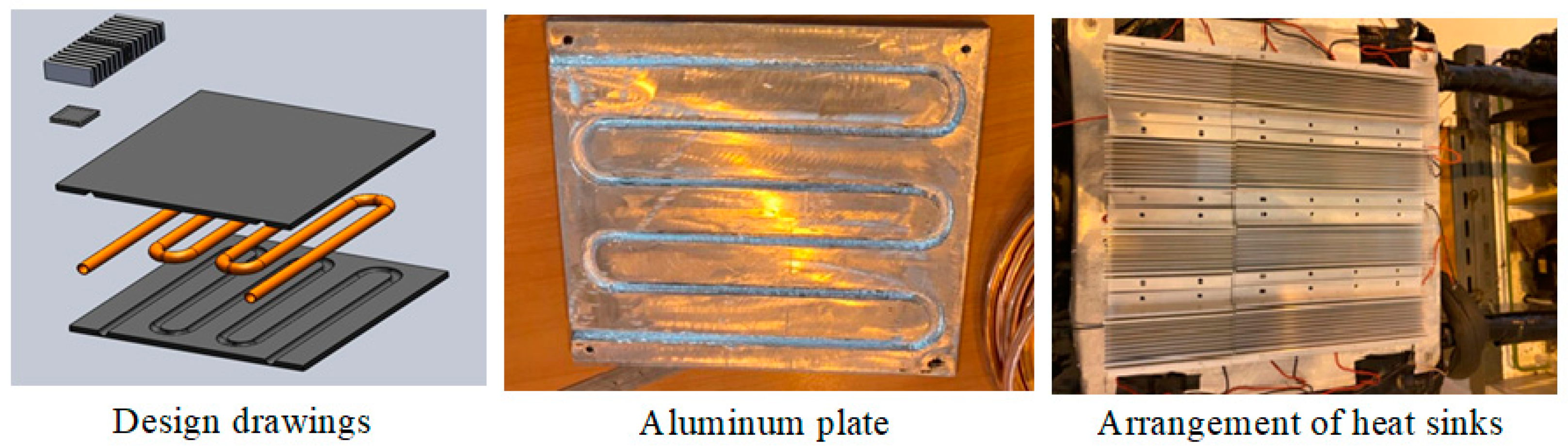
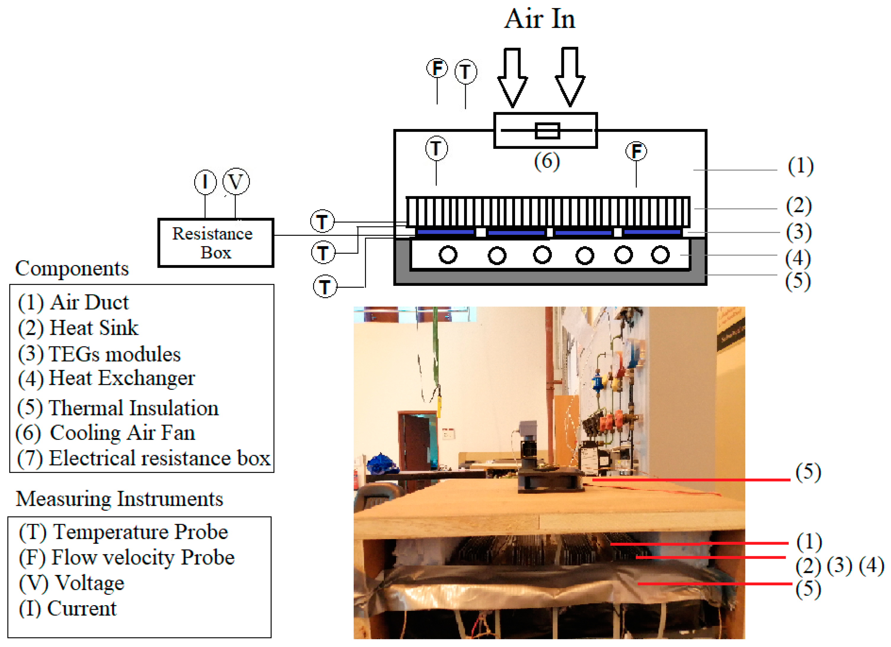
3. Design and Manufacturing of Heat Exchanger TEGs Unit (HE-TEGs)

Figure 2 shows the design drawing for HE-TEGs unit and manufacturing of plate and tube heat exchanger. The heat exchanger is manufactured using an aluminum plate of dimensions 300 mm × 300 mm and 8 mm thickness. The tube diameter is selected as 15 mm to be in the same order of magnitude of refrigerant pipe diameter at the exit of the compressor. The copper tubes are inserted inside the plate using a milling process. Assembly of HE-TEGs unit and installed measuring instruments are shown in Figure 3. To ensure good thermal contact between the copper tubes and aluminum plate, a thermal grease is used before fixing the tubes in their place. Screw holes and bolts are used for pressure assembly of the two plates. Sixteen commercial HP-127-1.4-1.15-71 thermoelectric modules of dimensions 40 mm × 40 mm × 3.9 mm are used as TEGs. The TEGs modules are installed on the top plate of HE. Specifications of the thermoelectric module at 50 °C hot side temperature are Vmax = 17.9 V, Imax = 8 A, Qmax = 87.7 W and DTmax = 80 °C [21]. These modules are rated for use at temperatures up to 80 °C. They are arranged in rows with 20 mm spacing and 40 mm from the edge of the plate. Aluminum heat sinks are arranged in four rows and installed directly on the top of the TEGs. Heat sinks have 25 cm length, 4 cm width and 10 fins each. Thermal grease is used between surfaces for good thermal contact. Pressure assembly of heat sinks, TEGs and HE plate is achieved using plastic fastening strips that are sufficiently tightened for good contact between the assembled parts. The heat exchanger plate is insulated using polyurethane insulation of 5 cm thickness at the bottom and sides of the heat exchanger. The HE-TEGs are then enclosed in wooden box. A cooling air fan is installed at the top. The cooling fan input voltage is 12 volts DC and 0.22 A electric current with dimensions of 9 cm × 9 cm. The fan directs cooling air to cool the heat sinks and the air exits from the two sides of the wooden box.
Measuring instruments include four temperature probes to measure the average surface temperature of the heat exchanger plate. The temperature at the bottom and top of selected TEG modules as well as the heat sink surface temperature are also measured using T-type thermocouples. The cooling air flow temperature and velocity are measured by averaging the readings of velocity meter and type T thermocouple at five different locations across the inlet and outlet cross sections. The voltage and current output from the TEGs unit at different values of load resistance are measured using a digital multi-meter and a variable resistance box.

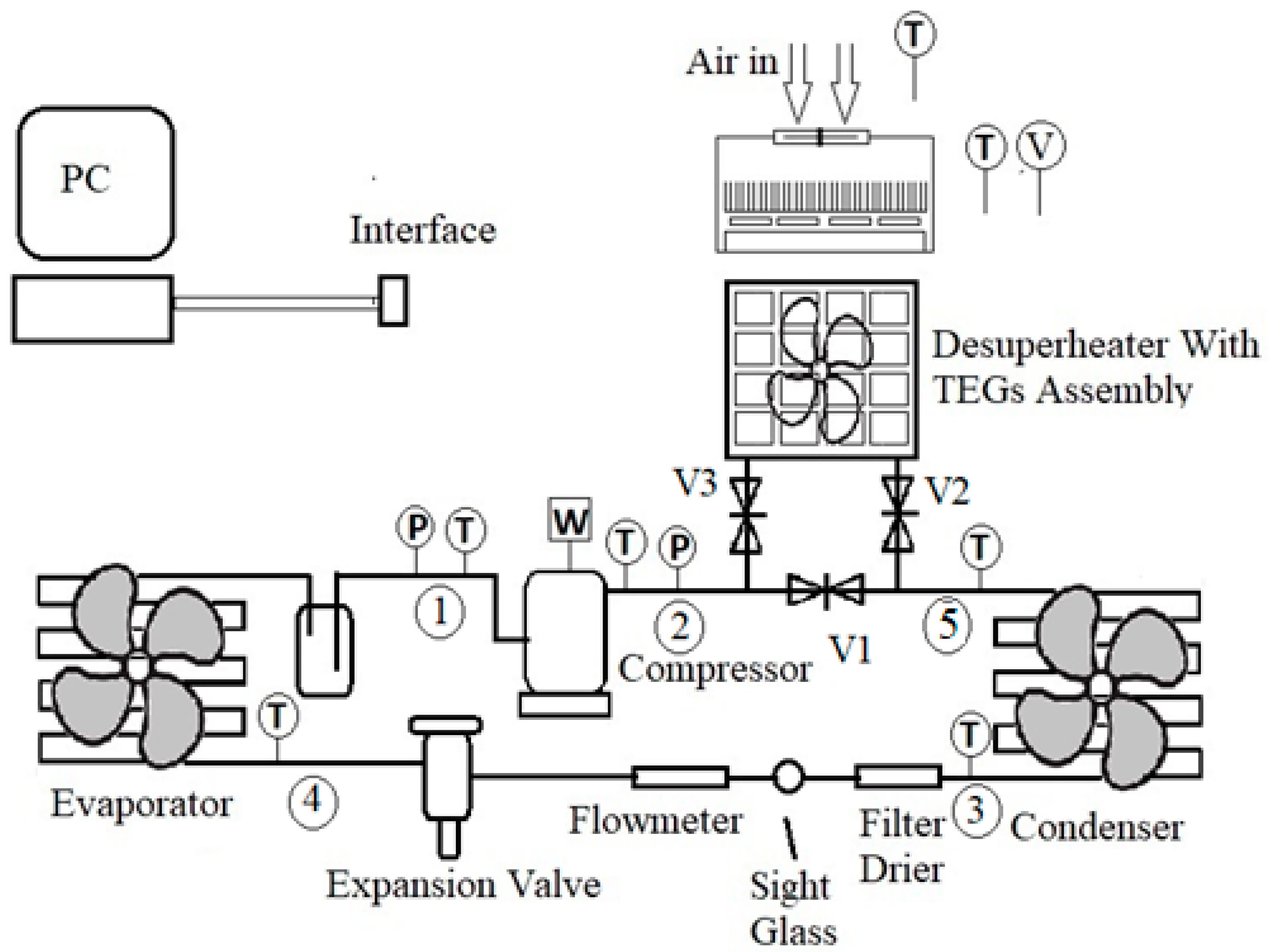
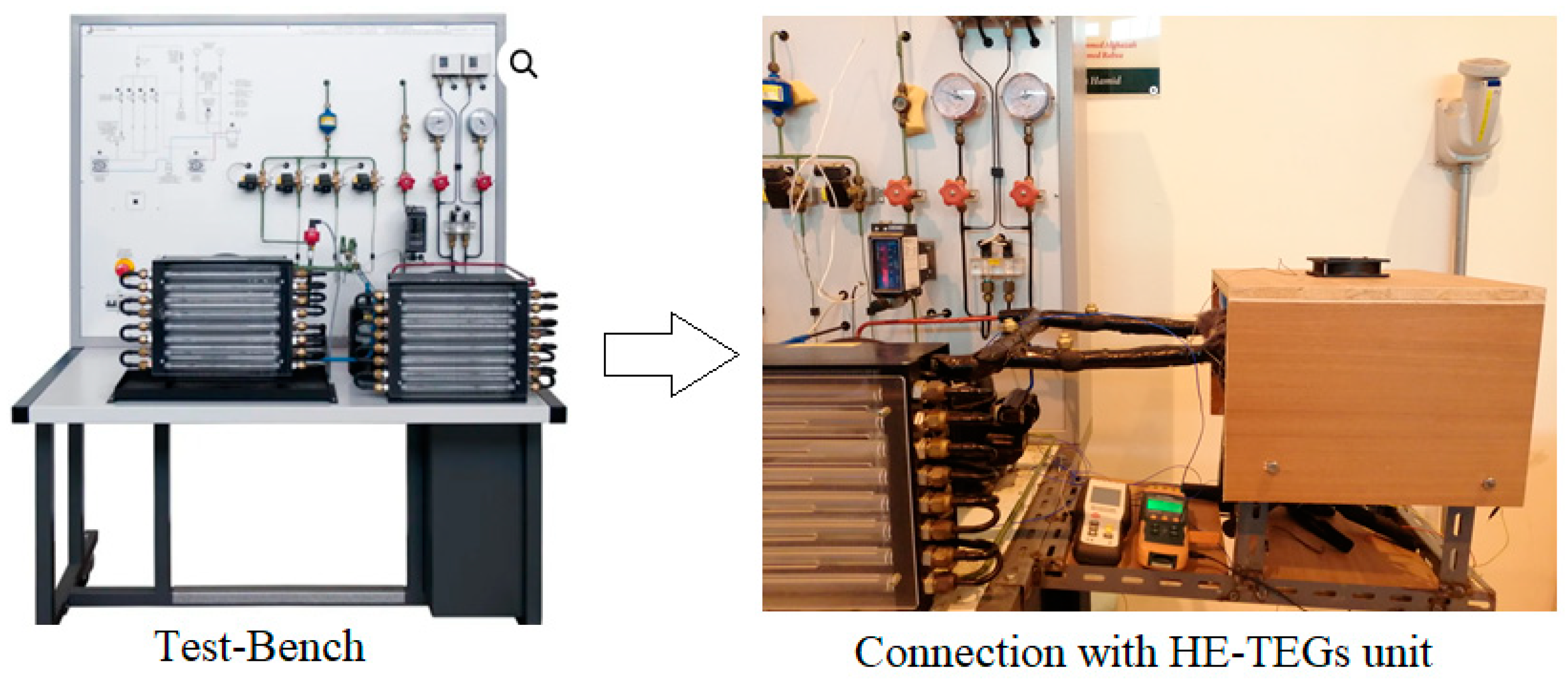
4. System Integration and Experimental Set-up

The experiments are carried out by integrating the TEG-Heat exchanger unit into a computerized experimental refrigeration test unit as shown in Figure 1. Pictures of the complete integrated system are photographed and shown in Figure 4 with a focus on the connection with the HE-TEGs unit. The refrigeration system is equipped with a hermetic reciprocating compressor loaded with refrigerant 134a. The compressor bore is 24 mm, stroke is 20 mm and maximum condensing pressures is 16.2 bar. The air-cooled condenser and evaporator are provided with fans with electronic speed variator, to simulate plant operation at different operating conditions. The inlet air temperature to the condenser and evaporator is the ambient temperature. The expansion and regulation of refrigerant liquid flow toward the evaporator is made via an electronic valve controlled from PC or via three capillaries with different section or length. The test rig has the facility to analyze the system behavior versus the variation of expansion device valve opening degree (when the electronic valve is used for expansion) and air flow rate at condenser and/or evaporator.
Integration of the HE-TEGs unit in the refrigeration system has been performed using manual shut-off valves (V1, V2 and V3) installed after the compressor, as shown in Figure 1. The use of manual shut off valves allows running the system in normal operation mode by closing valves (V2, V3) and opening valve V1. Allowing refrigerant flow to the HE-TEGs unit is achieved by opening valves (V2, V3) and closing valve V1. In the experiments, ambient air is used to cool the HE-TEGs unit. The use of ambient air for cooling is applicable for household refrigeration units. For split air conditioning units, the present study proposes to use part of the return air from the air-conditioned room in cooling the HE-TEGs unit to enhance the TEGs performance. Cooling of HE-TEGs unit using outside air in AC split units would result in low performance of TEGs modules.

5. Evaluation of Performance Parameters

The measuring instruments in the unit include high- and low-pressure gauges and transducers installed before and after the compressor. An electronic flow meter is installed after the condenser for measuring the refrigerant volume flow rate in litre/min. The unit is equipped with test points for thermometric probes to measure the refrigerant temperature before and after each component of the cycle. The measurement of temperature and pressure at different points of the cycle is used to calculate the refrigerant properties (such as enthalpy, density, entropy) at the inlet and exit of each system component using R134a property tables. These values are used for performing energy balance of evaporator, condenser, heat exchanger and compressor. Moreover, the unit is provided with an ammeter, voltmeter and power factor meter to measure total electric power consumption of the plant including compressor motor, electrical installations, condenser and evaporator fans.
The following calculations are used for the analysis of unit performance. Reference to Figure 1 is made for position and labelling of points used in the below relations. The refrigerant mass flow rate, m ˙ r e f is calculated using:
m ˙ r e f = V ˙ 3   ρ 3
where V ˙ 3   and   ρ 3 are the refrigerant volume flow rate and the refrigerant liquid density at point 3 after the condenser. The first one is measured by the flow meter, while the latter is calculated using the property tables of R134a and measured values of pressure and temperature at the exit of the condenser.
The waste heat rate in the superheated refrigerant region after the condenser is calculated using the following relation:
Q s u p = m r e f ˙   ( h 2 h g )
where h2 is the refrigerant enthalpy at the compressor outlet and hg is saturated refrigerant vapour enthalpy at the compressor discharge pressure.
The heat recovery rate after installation of heat exchanger is calculated as,
Q H E = m r e f ˙   ( h 2 h 5 )
where h2 and h5 are the values of refrigerant enthalpy at the inlet and exit of waste heat recovery heat exchanger.
The overall coefficient of performance of the system (COP) is calculated as the ratio of refrigeration capacity produced by the unit to the total power consumption.
C O P = m r e f ˙   ( h 1 h 4 ) P E l e c t r i c  
where h 1   a n d   h 4 are the refrigerant enthalpy at the evaporator outlet and inlet, respectively. The total electric power consumption of the unit (PElectric) includes the power of compressor and the cooling fans of condenser and evaporator. The higher the COP, the more efficient the refrigeration system.
Energy balance of TEGs unit is written as follows:
Q H E = P T E G s + Q c o o l i n g + Q l o s s
where QHE is the waste heat recovered by the heat exchanger, PTEGs is the electric power output from the TEG modules, Qcooling is the heat transferred to the cooling air and Qloss is the heat loss from the HE-TEGs unit. Measurements of the cooling fan air flow rate, cooling air inlet and outlet temperature are used to calculate the value of Qcooling as follows:
Q c o o l i n g = m ˙ a i r   c p   a i r ( T a i r ,   o u t T a i r ,   i n )  
The efficiency of the HE-TEGs unit can be estimated as:
η T E G s = P T E G s Q H E
The uncertainty of various measuring instruments used in the experiments are shown in Table 1.
The uncertainty in a calculated dependent variable (UR) as function of uncertainties measured independent variables (x1, x2, x3, …, xn) is calculated using the theory of uncertainty propagation in [22] as:
U R = [ ( U x 1 U x 1 ) 2 + ( U x 2 U x 2 ) 2 + + ( U x n U x n ) 2   ] 1 / 2
Using Equation (8), the maximum uncertainties of measured COP, cooling capacity and the TEGs power are found to be around ±3.2%, ±2.4% and ±4%, respectively.
The experimental procedure is carried out as follows; firstly, the AC unit is checked for any problems or leaks and then the AC unit is turned on. The condenser fan is fixed at 100%, and experiments are repeated at different values of evaporator fan speeds ranging from 100% to 20%. The same experiments are repeated by fixing the evaporator fan at 100% and varying the condenser fan from 20 to 100%. The test results that are carried out for the base case of refrigeration system without any modifications are considered as the baseline for comparison with the results obtained with integration of the HE-TEGs unit. Table 2 shows the summary of the present experiments and operating conditions. The ambient temperature is maintained at about 27 °C in all the experiments. The measured values of compressor discharge and suction pressure during the experiments are also included in Table 2. The system power consumption during the experiments ranges from 340 to 435 W.

6. Results and Discussion

Analysis and discussion of the experimental results are discussed in the following sections. Investigation of superheat temperature and waste heat in the superheat region is presented first because of its importance in the design of HE-TEGs unit. The effect of using HE-TEGs on the refrigeration system performance is evaluated by the analysis of overall coefficient of performance of the system. Moreover, the output power from the HE-TEGs unit is analyzed and compared to the needed power for the heat sinks cooling fan. Analysis of the cycle on the p-h diagram before and after integration of HE-TEGs unit reveals the important changes introduced by using the HE-TEGs unit and their effect on the cycle performance.

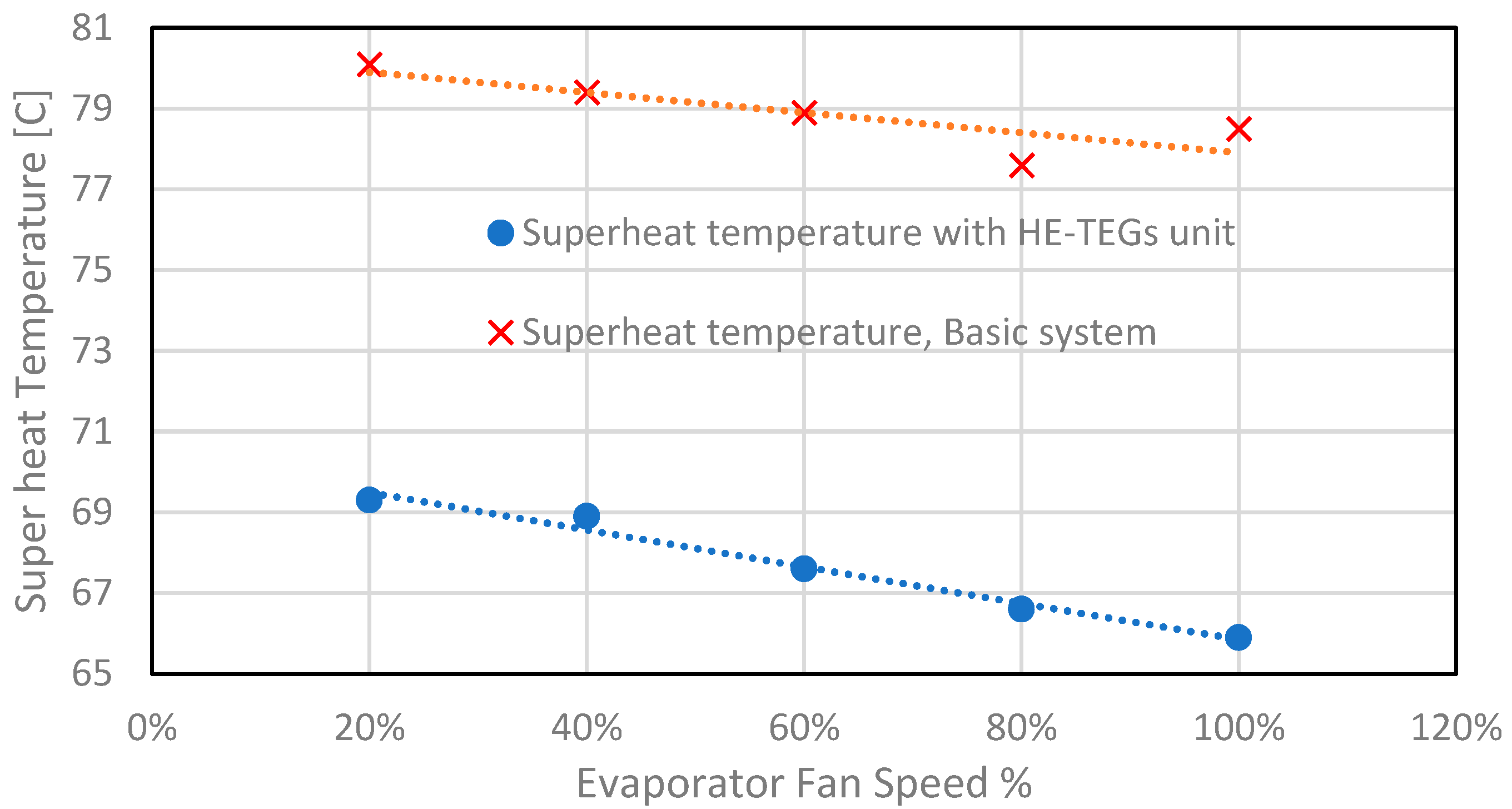
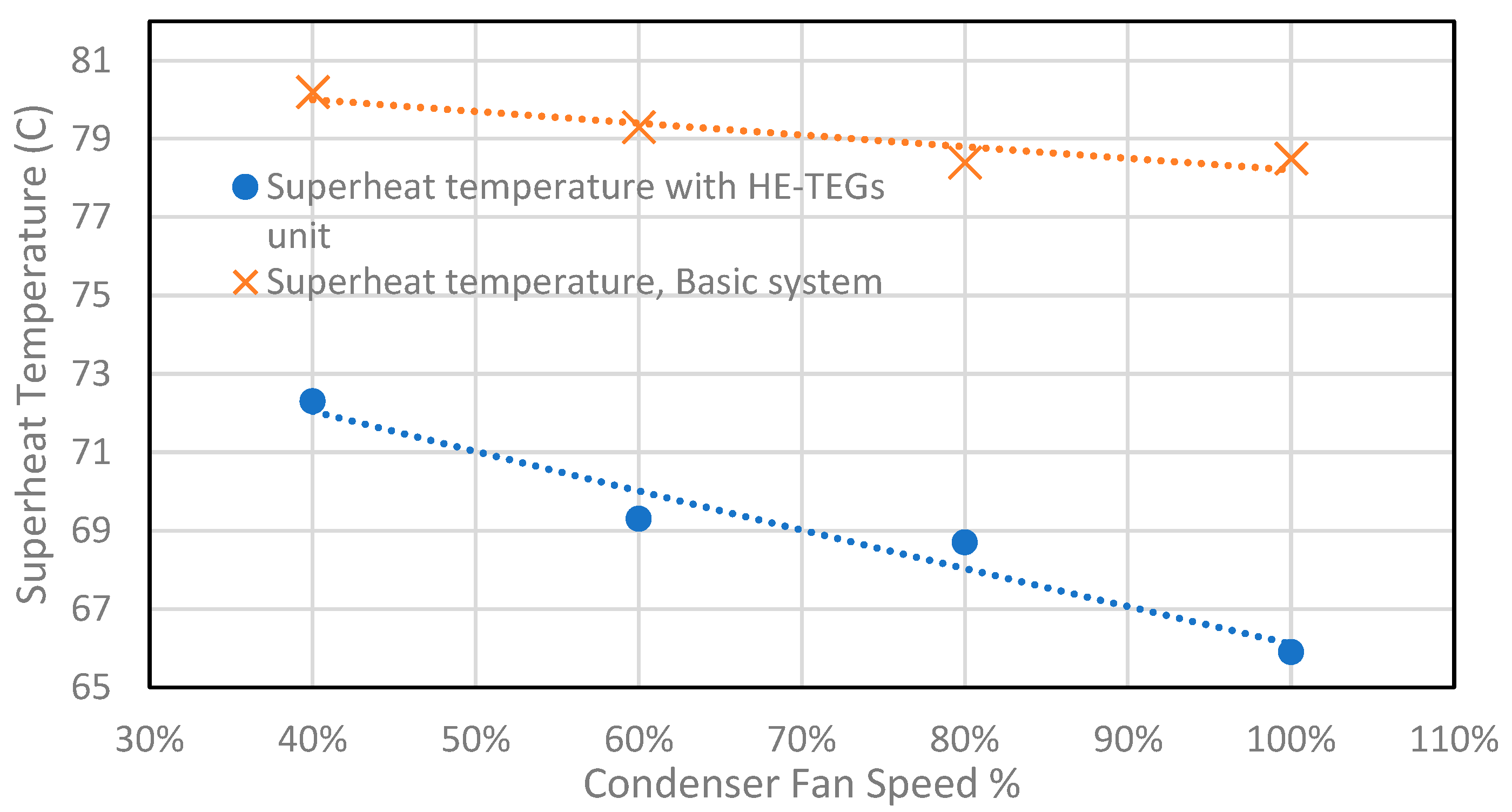
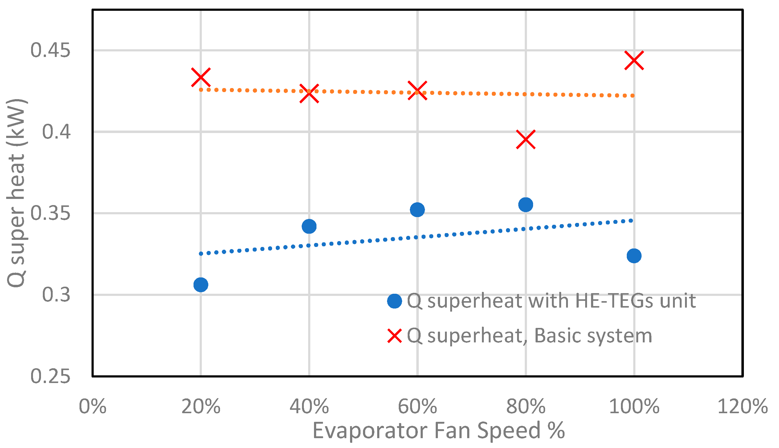
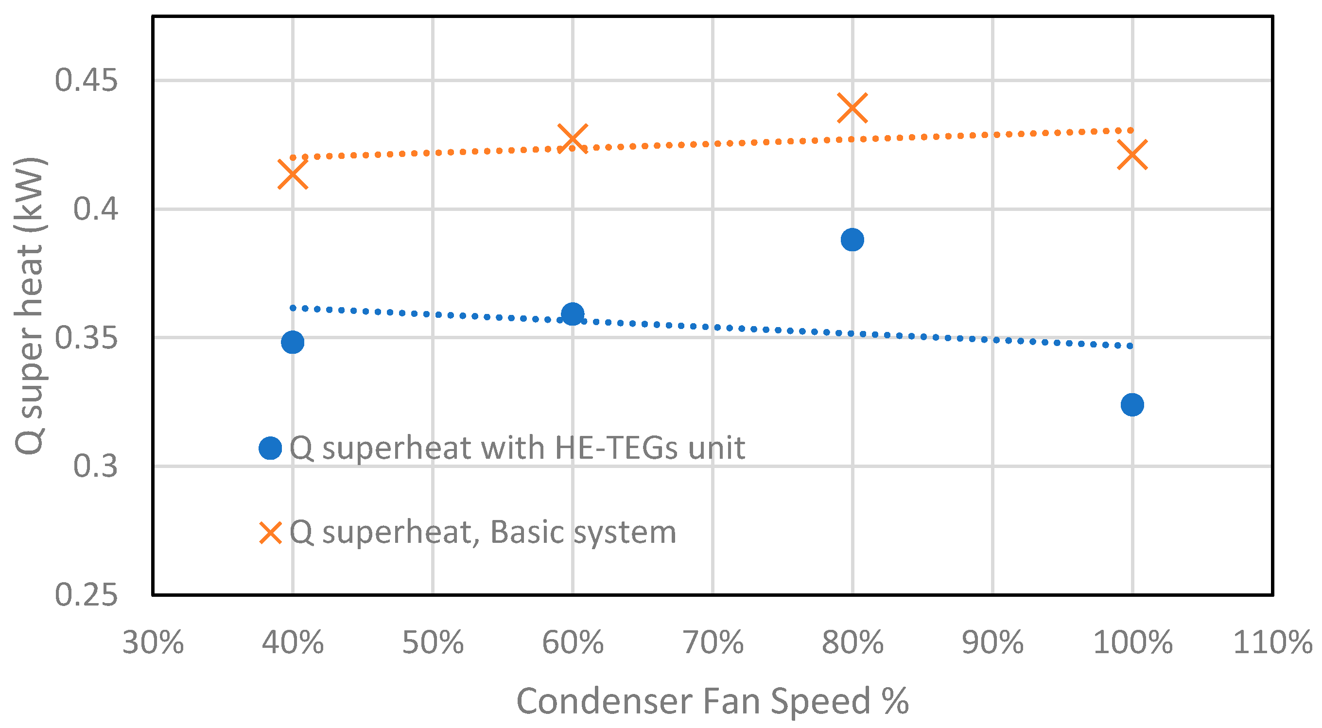
6.1. Superheat Temperature and Waste Heat Recovery

The variation of superheated refrigerant temperature at the compressor exit with evaporator fan speed is presented in Figure 5. The markers show the measurement points, and the lines show the trendlines. It is clearly noticed that the superheat temperature increases with decreasing the evaporator fan speed. The value of superheat temperature changes from 80 °C to 78 °C for the reference case of basic cycle without HE-TEGs unit. Moreover, installation of HE-TEGs unit reduces the value of superheat temperature by about 10 degrees. The same trend in the decrease of superheat temperature is also observed at different values of condenser load as shown in Figure 6. These results assert the expected decrease of superheat temperature with the installation of heat recovery heat exchanger equipped with TEGs.
The amount of available Q-superheat decreases with the installation of HE-TEGs unit, as shown in Figure 7 and Figure 8. It is clearly seen that the value of Q-superheat is function of the refrigerant mass flow rate and the difference of refrigerant enthalpy between the compressor outlet and the saturated vapor enthalpy at the discharge pressure. The decrease in the values of Q-superheat and superheat temperature with the installation of HE-TEGs unit as compared to base case should be considered from two perspectives. The first one concerns the design stage of HE-TEGs unit where calculations should consider dynamic response of the refrigeration system and the reduction in available superheat after installation of the unit. The second perspective is the positive effect of this reduction in superheat on the refrigeration system performance which will be explained in the following sections.

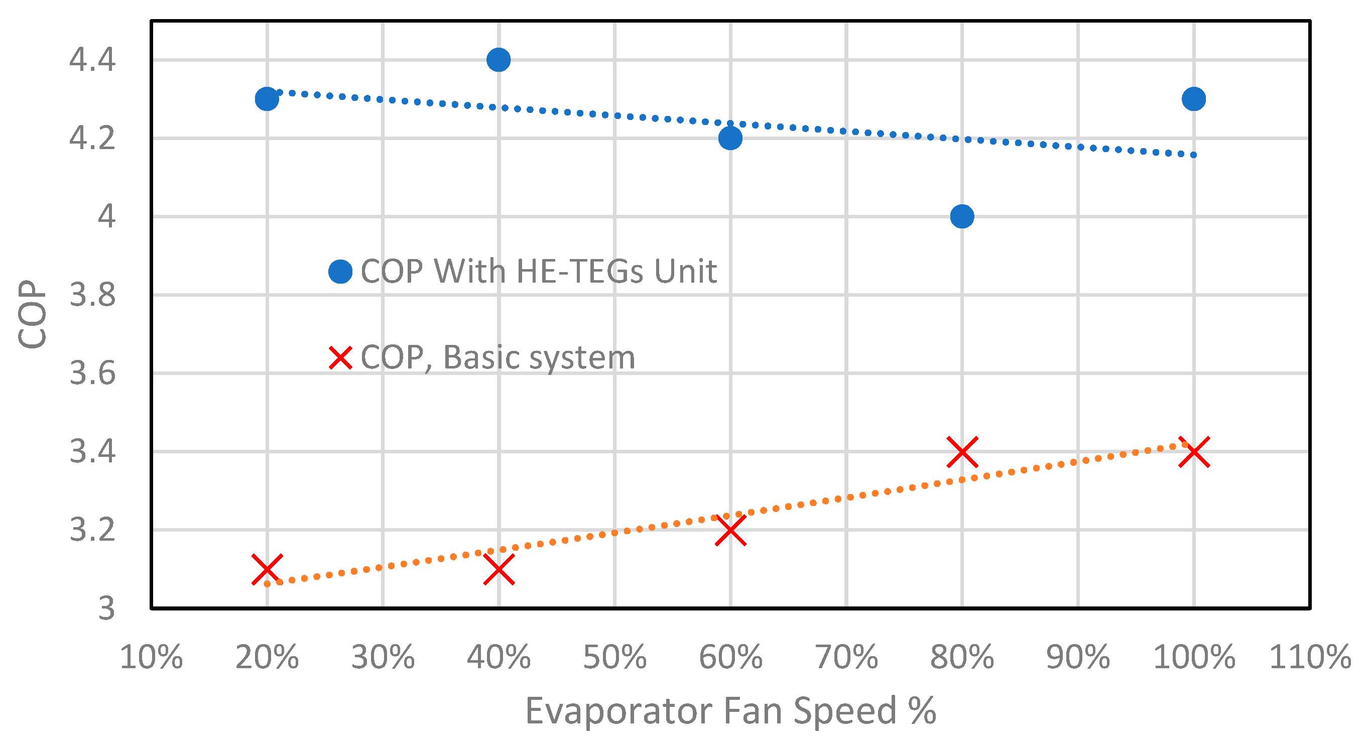
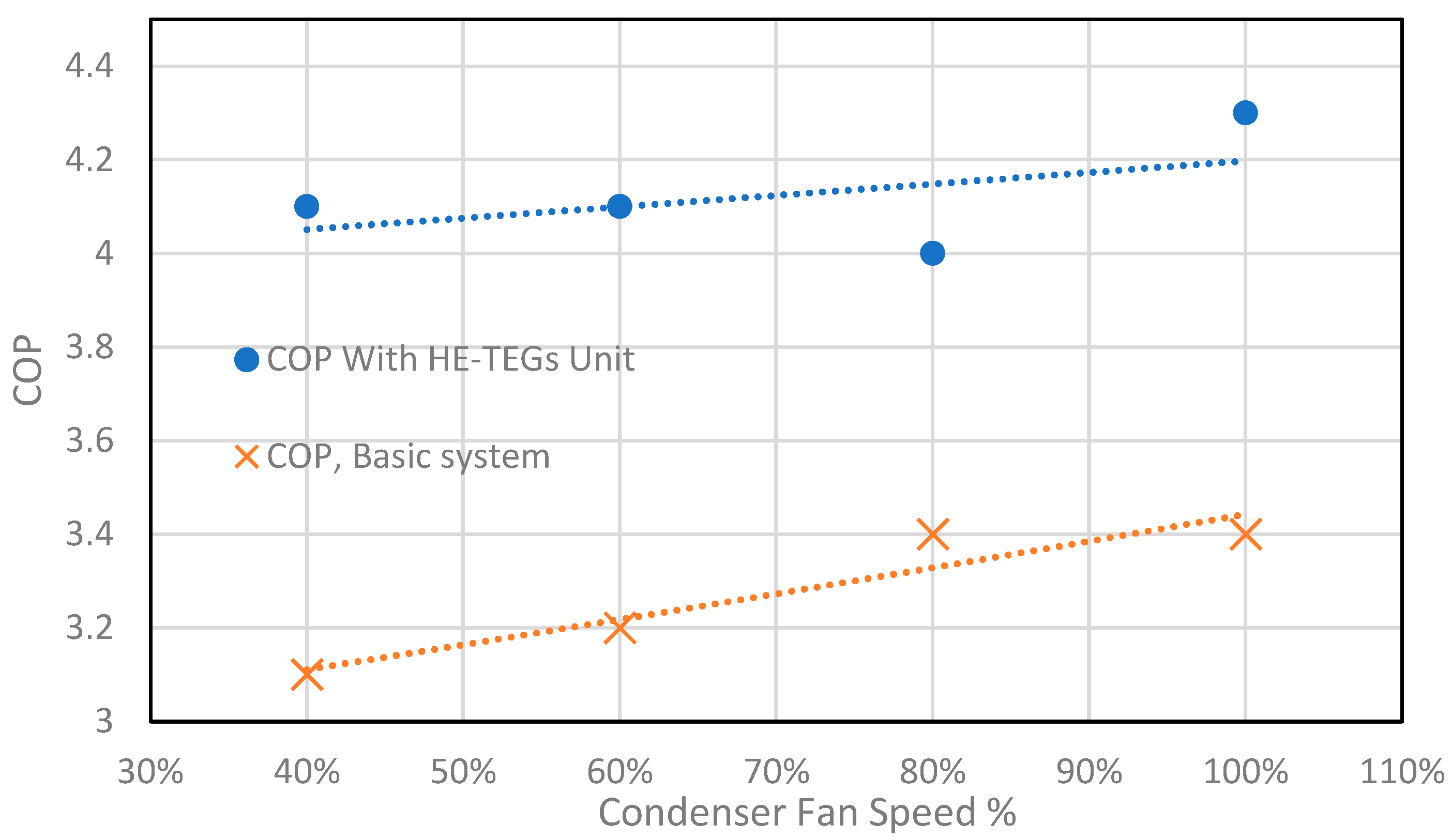
6.2. Overall Coefficient of Performance of Refrigeration System

Installation of HE-TEGs unit decreases the compressor temperature and improve the efficiency of the compression process which is manifested by lower values of superheat temperature. Consequently, as shown in Figure 9 and Figure 10, the overall coefficient of performance of refrigeration unit using HE-TEGs unit increases by values ranging from 17% to 32%. This increase in COP is attributed as due to increase in cooling capacity and decrease in compressor power. This important conclusion is proved by comparison of cycle p-h diagram with and without HE-TEGs unit in Section 6.4. The same behavior is observed using different values of condenser cooling fan speed.

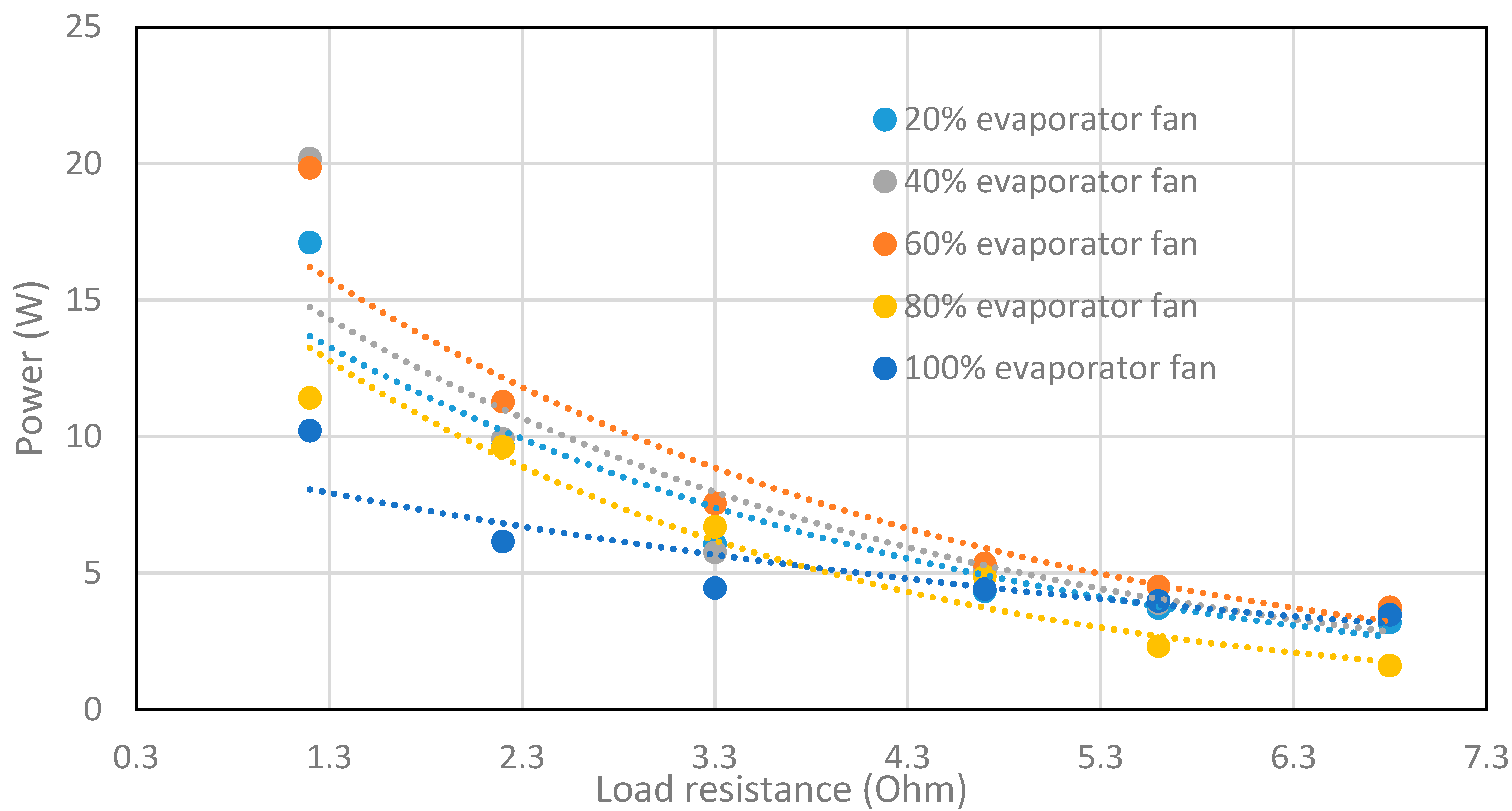
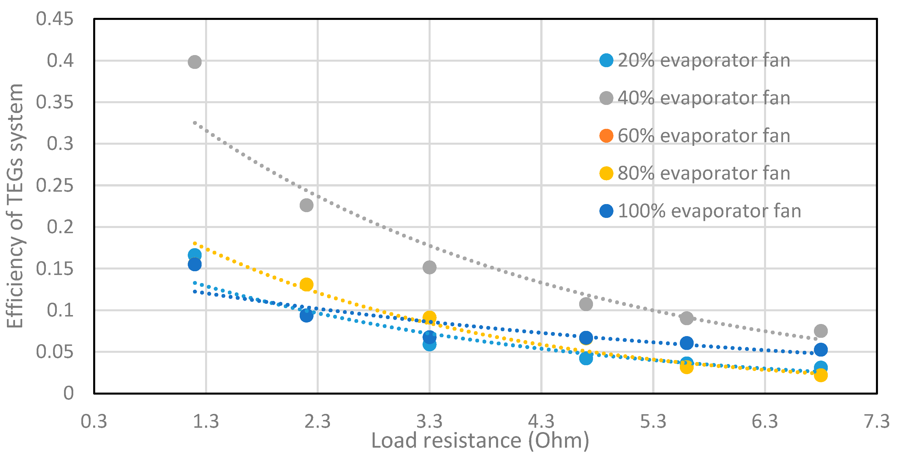
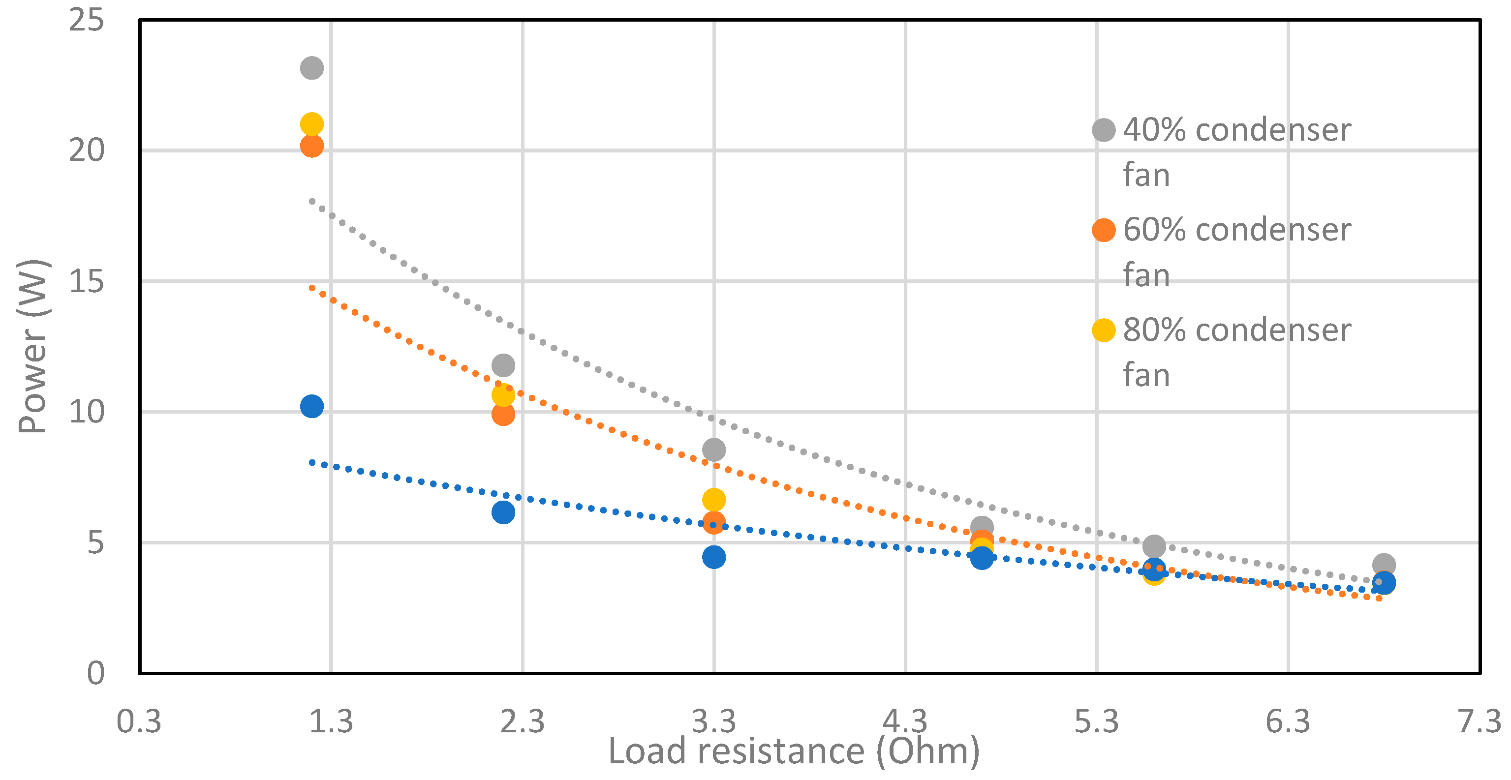
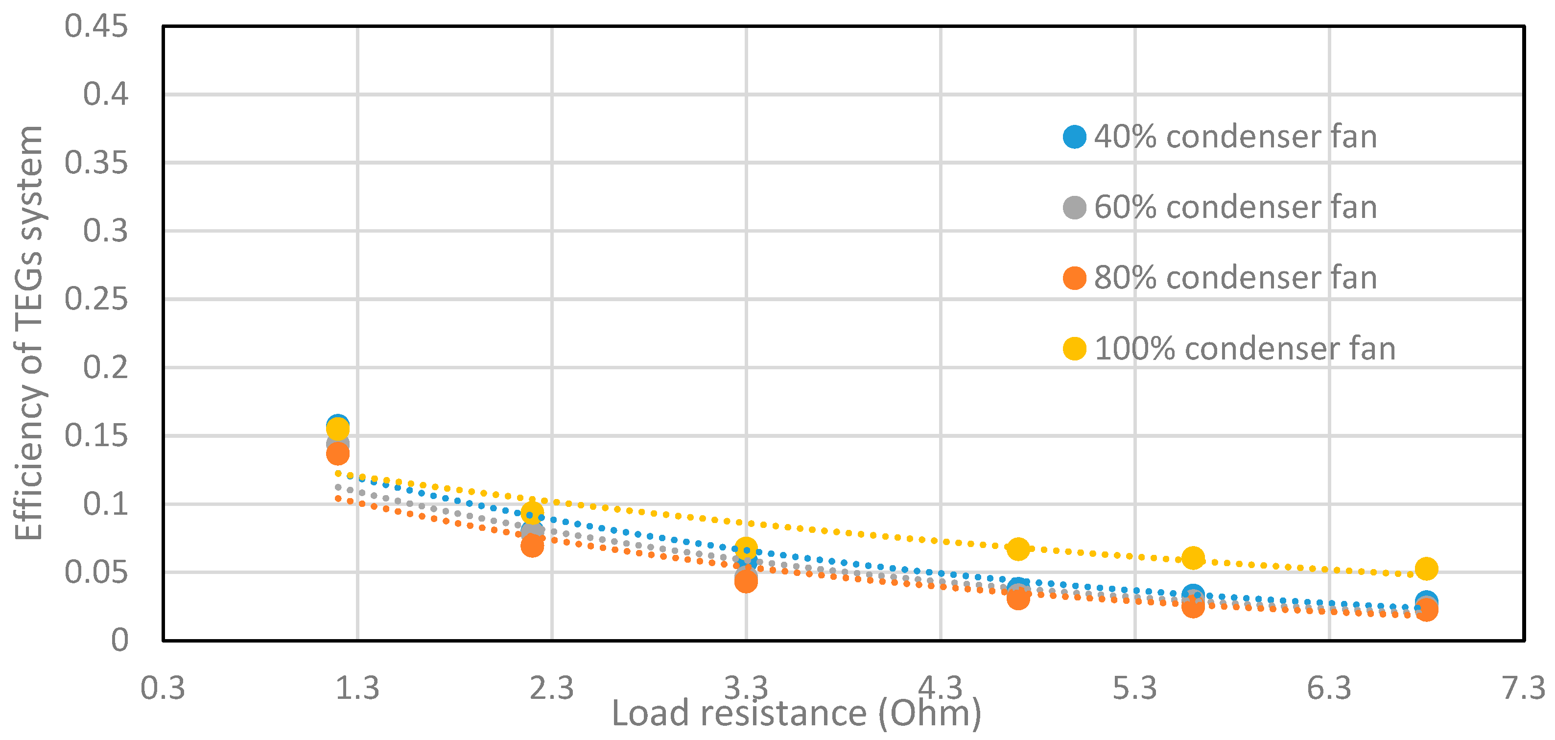
6.3. Analysis of TEGs Performance

Analysis of the electric power output from the TEGs at different values of evaporator load is shown in Figure 11. It is clearly seen that, the electric power output from TEGs increases with the decrease of evaporator load. This trend can be explained by the increase of superheat temperature. Moreover, the maximum power output from the TEGs ranges between 10 and 20 W at about 1.13 Ohm load resistance. The variation of TEGs efficiency calculated using Equation (7) with load resistance is shown in Figure 12. It can be observed that the efficiency of TEGs decreases with the increase of load resistance and increases with the decrease of evaporator load. Figure 13 and Figure 14 show the variation of TEGs power and efficiency at different values of condenser load. It is observed that low values of condenser fan speed, representing condenser conditions in hot summer days, results in high values of output power from the TEGs. However, the variation TEGs efficiency with the condenser fan speed is smaller than the variation with the evaporator fan speed. The efficiency of TEGs slightly decreases with the increase of condenser fan speed.
Considering that the superheat temperature without HE-TEGs could reach a value of 80 °C The TEG module electric power is directly related to the temperature difference between the two sides of the module. One can perform his calculation for system design based on this maximum value of superheat temperature. However, it should be observed that, when the module is placed at the top of the HE plate, the temperature difference between both sides of the module is significantly smaller. This can be explained as due to the dynamic response of refrigeration cycle operating conditions and because of the heat transfer by conduction through both TEG sides and heat transfer between the module and the ambient air. In the present study, the average values of measured refrigerant inlet and outlet temperatures ranges from 62.4 °C to 66.5 °C and 52.3 °C to 59.5 °C. The average hot side temperature of TEGs ranges from 47.2 °C to 52.3 °C. The average ambient temperature is recorded to be about 27 °C. Indicating a temperature difference potential of about 30 °C. However, this results in limitations in the maximum power output from the TEGs. However, this power is found to be sufficient for operation of the heat sink fan used for cooling of TEGs.

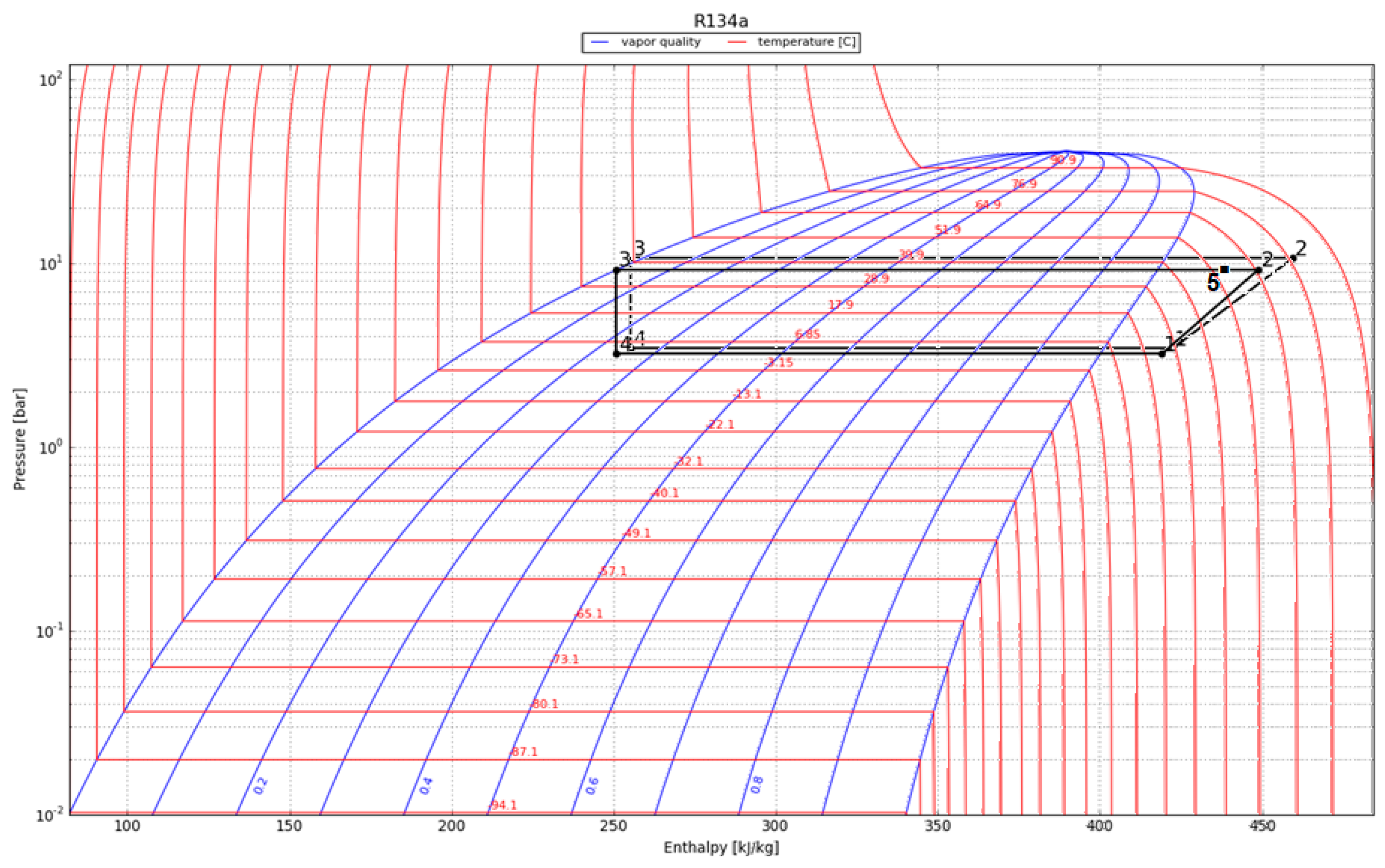
6.4. Analysis of Refrigeration Cycle

The previous results show that the integration of HE-TEGs affects the performance of refrigeration cycle. Analysis of the cycle on the p-h diagram before and after integration of HE-TEGs unit is shown in Figure 15. This analysis would give an overall picture of the dynamic changes of the cycle introduced by using HE-TEGs unit. Please refer to Figure 1 for labelling of different points in the system. The cycle of basic system is represented by dotted lines whereas the cycle with HE-TEGs unit is represented by solid lines. It can be observed that the integration of HE-TEGs unit results in a reduction of condenser and evaporator pressures, as shown in Table 2. Reduction in condensation pressure may be related to heat recovered by the HE-TEGs unit during the process from point 2 to 5 which results in more effective cooling of refrigerant in the condenser tubes. Heat transfer in the condenser is enhanced because of reduction of volume occupied by refrigerant gas at the entry of compressor and high heat transfer coefficient during the condensation process. As compared to the basic system, the compressor outlet temperature decreases by about 10 °C and the pressure ratio of compression process decreases from 3.1 to 2.88. Therefore, compressor work, indicated by the difference in enthalpy change during the compression process from point 1 to 2 between compressor inlet and outlet, decreases with the integration of HE-TEGs unit. On the other hand, the refrigeration effect represented by the process from point 4 to point 1 between the evaporator inlet and outlet, increases in the presence of HE-TEGs unit. Consequently, these changes result in an increase in the overall system COP. The potential for enhancement of cycle performance can be increased by integration of additional HE-TEGs units.

6.5. Exergy Analsyis Sustainbility Indicator

It should be mentioned that the improvement of the energy efficiency of air conditioning systems is a major concern for sustainable development. Recently, Grisolia et al. [23] introduced a new bioeconomic indicator to avoid the difficulties in evaluating processes and technologies from the sustainability point of view. The new indicator is defined as:
I = E x e r g y   l o s t   i n   t h e   s y s t e m Q u a n t i t y   r e l a t e d   t o   t e h   r e q u i r e d   e f f e c t = T o S ˙ g Q ˙ c o o l i n g
where To is the environmental temperature, S ˙ g is the entropy generation in the system, Q ˙ c o o l i n g is the cooling capacity of the system. Processes with lower entropy generation rate are able to realize energy conversion more efficiecnly and therefore are more sustainable. Low values of the indicator indicate a more efficient and higher sustainable level of the system. The sustainability indicator proposed by Grisolia et al. [23] is used in the present study for comparison of refrigeration system with and without integration of HE-TEGs unit. Moreover, analysis of the exergy destruction in each component reveals the enhancement introduced by HE-TEGs unit integration.
The total exergy destruction in the system (ED = To  S ˙ g ) is equal to the sum of exergy destruction in each component of the system. The exergy destruction in each component of the system is expressed as [24,25]:
E D =   ( m ˙   e x ) i n   ( m ˙   e x ) o u t +   ( Q ˙ ( 1 T o T ) ) i n     ( Q ˙ ( 1 T o T ) ) o u t ± W ˙
The first two terms on the right-hand side represent exergy flow entering and leaving the component. The third and fourth terms are the exergy destruction associated with heat transfer (Q) from the source maintained at constant temperature (T). The last term is the work done on or by the component.
Using Equation (10) and the experimental measurements for state points obtained with and without integration of HE-TEGs unit. Exergy destruction values in each system component are listed Table 3. It can be observed that the integration of HE-TEGs unit and its effect on refrigeration cycle result in remarkable reduction in exergy destruction in the condenser and compressor. The total exergy destruction is decreased by about 14%. The sustainability indicator decreases from 0.350 for the basic system to 0.308 for the refrigeration system with HE-TEGs unit. These results support the promising potential of the present concept.

6.6. Economic Analysis

The previous results can be used to perform an economic study of the feasibility of the proposed integration of HE-TEGs unit in the refrigeration system. For guidance, the analysis is carried out using the performance data of the present experimental unit. The TEGs modules constitute the main cost of the HE-TEGs unit. The cost of a single module can reach $1 to $2 in the market and lower process can be obtained for bulky demands. Other cost items include the heat sinks, fan, Aluminum heat exchanger, copper tubes and fittings. The present HE-TEGs unit includes 16 TEGs modules and can be manufactured and integrated in the refrigeration unit with a total cost of about $80. Considering the case with 100% evaporator load and varying condenser fan speed to represent the variation of ambient conditions all over the year. As shown in Table 4, the enchantment of COP results in about 17% to 32% saving in electric power consumption as compared to the basic system without TE-TEGs unit. Using electric power consumption of the basic unit the annual savings in power consumption and payback period are shown in Table 3. These values are obtained assuming 15 daily operating hours for 80% of the year typical for weather conditions in Saudi Arabia. It can be observed that the payback period ranges from 2 to 4 years. This payback period is very promising in view of the low price of kW·hr in Saudi Arabia [26] and the lifetime of AC and refrigeration units that exceed 10 years. One could also consider the positive impact on the environment by the reduction of CO2 equivalent to this electric energy savings. Future work should consider the sizing and detailed thermo-economic analysis of the proposed system using different AC and refrigeration units. Using multiple HE-TEGs units can further enhance the system performance.

7. Conclusions

An experimental study has been carried out for analysis and assessment of refrigeration system performance with the integration of a heat exchanger thermoelectric generators unit for de-superheating the refrigerant gas after the compression process. Experiments have been carried out on a laboratory unit of small cooling capacity for a wide range of operating conditions by variation of condenser and evaporator loads.
Assessment of the performance parameters of refrigeration system shows that the overall refrigeration system coefficient of performance (COP) using HE-TEGs desuperheater unit increases by values ranging from 17% to 32% depending on the condenser and evaporator loads. The output power of HE-TEGs unit ranges from 3 to 20 W. Low values of condenser fan speed, representing condenser conditions in hot summer days, results in high values of output power from the TEGs. The TEGs output power is found to sufficient for driving the cooling fan of TEGs heat sinks and provide a passive de-superheating system without external sources of electricity.
Analysis of p-h diagram of refrigeration cycle shows that integration of HETEGs unit result in reduction in condensation pressure, compressor outlet temperature and pressure ratio. Heat transfer in the condenser is enhanced because of reduction of volume occupied by refrigerant gas at the entry of compressor and high heat transfer coefficient during the condensation process. As compared to the basic system, the compressor work decreases and the refrigeration effect increases with the integration of HE-TEGs unit. Exergy analysis of system components shows that, as compared to the basic system, the integration of HE-TEGs unit results in remarkable reduction of exergy destruction in the compressor and condenser and a decrease in the value of sustainability indicator. Low values of the indicator indicate a more efficient and more sustainable level of the system. Economic feasibility of the proposed system shows a promising payback period. Further enhancement of the refrigeration cycle performance can be achieved by installation of additional HE-TEGs units.

Author Contributions

A.A. (Alaa Attar) is responsible for project administration, conceptualization, supervision, methodology; M.R. is responsible for conceptualization, supervision, methodology, investigation and original draft preparation; A.A. (Abdullah Abuhabaya) is responsible for resources, data curation, and validation; F.A. is responsible for formal analysis and writing review and editing; A.H. is responsible for writing, review and formal analysis. E.A. is responsible for formal analysis and writing review and editing. All authors have read and agreed to the published version of the manuscript.

Funding

This research project was funded by the deanship of scientific research (DSR) at King Abdulaziz University, Jeddah, under grant number G: 697-829-1441.

Data Availability Statement

Relevant data shall be available on request from the authors.

Acknowledgments

This research project was funded by the deanship of scientific research (DSR) at King Abdulaziz University, Jeddah, under grant number G: 697-829-1441. The authors, therefore, acknowledge with thanks DSR for technical and financial support.

Conflicts of Interest

The authors declare no conflict of interest.

References

  1. The Future of Cooling: Opportunities for Energy Efficient Air Conditioning, International Energy Agency. Technology Report. Available online: https://www.iea.org/reports/the-future-of-cooling (accessed on 2 December 2021).
  2. Hughes, B.R.; Chaudhry, H.N.; Ghani, S.A. A review of sustainable cooling technologies in buildings. Renew. Sustain. Energy Rev. 2011, 15, 3112–3120. [Google Scholar] [CrossRef]
  3. She, X.; Cong, L.; Nie, B.; Leng, G.; Peng, H.; Chen, Y.; Zhang, X.; Weng, T.; Yang, H.; Luo, Y. Energy-efficient and -economic technologies for air conditioning with vapor compression refrigeration: A comprehensive review. Appl. Energy 2018, 232, 157–186. [Google Scholar] [CrossRef]
  4. Gu, Z.; Liu, H.; Li, Y. Thermal energy recovery of air conditioning system––Heat recovery system calculation and phase change materials development. Appl. Therm. Eng. 2004, 24, 2511–2526. [Google Scholar] [CrossRef]
  5. Zhang, X.; Yu, S.; Yu, M.; Lin, Y. Experimental research on condensing heat recovery using phase change material. Appl. Therm. Eng. 2011, 31, 3736–3740. [Google Scholar] [CrossRef]
  6. Xia, M.; Yuan, Y.; Zhao, X.; Cao, X.; Tang, Z. Cold storage condensation heat recovery system with a novel composite phase change material. Appl. Energy 2016, 175, 259–268. [Google Scholar] [CrossRef]
  7. Byrne, P.; Fournaison, L.; Delahaye, A.; Oumeziane, Y.A.; Serres, L.; Loulergue, P.; Szymczyk, A.; Mugnier, D.; Malaval, J.; Bourdais, R.; et al. A review on the coupling of cooling, desalination and solar photovoltaic systems. Renew. Sustain. Energy Rev. 2015, 47, 703–717. [Google Scholar] [CrossRef]
  8. Slesarenko, V.V. Heat pumps as a source of heat energy for desalination of seawater. Desalination 2001, 139, 405–410. [Google Scholar] [CrossRef]
  9. Byrne, P.; Miriel, J.; Serres, L.; Ghoubali, R. Etude Simulée D’un Système De Dessalement D’eau De Mer Et De Production De Froid Par Thermofrigopompe Couplée À Des Panneaux Solaires. 2ème Colloque International Francophone En Energétique Et Mécanique; CIFEM: Ouagadougou, Burkina Faso, 2012. [Google Scholar]
  10. Byrne, P.; Ait Oumeziane, Y.; Serres, L.; Miriel, J. Etude Simulée D’un Système De Distillation Membranaire Pour Le Dessalement D’eau De Mer Couplé À Une Thermofrigopompe, 3ème Colloque International Francophone En Energétique Et Mécanique; CIFEM: Moroni, Comores, 2014. [Google Scholar]
  11. Byrne, P.; Ait Oumeziane, Y.; Serres, L.; Miriel, J. Study of a heat pump for simultaneous cooling and desalination. In Proceedings of the IMAT Conference, Kuala Lumpur, Malaysia, 26–27 November 2014. [Google Scholar]
  12. Aguilar, F.J.; Quiles, P.V.; Aledo, S. Operation and energy efficiency of a hybrid air conditioner simultaneously connected to the grid and to photovoltaic panels. Energy Procedia 2014, 48, 768–777. [Google Scholar] [CrossRef] [Green Version]
  13. Rady, M.; Albatati, F.; Hegab, A.; Abuhabaya, A.; Attar, A. Design and analysis of waste heat recovery from residential air conditioning units for cooling and pure water production. Int. J. Low-Carbon Technol. 2021, 16, 1018–1032. [Google Scholar] [CrossRef]
  14. Pourkiaei, S.M.; Ahmadi, M.H.; Sadeghzadeh, M.; Moosavi, S.; Pourfayaz, F.; Chen, L.; Yazdi, M.A.P.; Kumar, R. Thermoelectric cooler and thermoelectric generator devices: A review of present and potential applications, modeling and materials. Energy 2019, 186, 115849. [Google Scholar] [CrossRef]
  15. Ramadan, M.; Ali, S.; Bazzi, H.; Khaled, M. New hybrid system combining TEG, condenser hot air and exhaust airflow of all-air HVAC systems. Case Stud. Therm. Eng. 2017, 10, 154–160. [Google Scholar] [CrossRef]
  16. Damanhuri, A.A.M.; Abdullah, M.I.H.C.; Lubis, A.M.H.S.; Zakaria, M.Z.; Hussin, M.S.F.; Kasno, M.A. Development Of TEG Peltier Device For Heat Harvesting From 1.5 HP Split Unit Air Conditioning System. Int. J. Appl. Eng. Res. 2018, 13, 2390–2394. [Google Scholar]
  17. Navarro-Peris, E.; Corberan, J.M.; Ancik, Z. Evaluation of the potential recovery of compressor heat losses to enhance the efficiency of refrigeration systems by means of thermoelectric generation. Appl. Therm. Eng. 2015, 89, 755–762. [Google Scholar] [CrossRef]
  18. Sánchez, D.; Aranguren, P.; Casi, A.; Llopis, R.; Cabello, R.; Astrain, D. Experimental enhancement of a CO2 transcritical refrigerating plant including thermoelectric subcooling. Int. J. Refrig. 2020, 120, 178–187. [Google Scholar] [CrossRef]
  19. Radermacher, R.; Yang, B.; Hwang, Y. Integrating alternative and conventional cooling technologies. ASHRAE 2007, 49, 28–35. [Google Scholar]
  20. Wantha, C. Experimental investigation of the influence of thermoelectric subcooler on the performance of R134a refrigeration systems. Appl. Therm. Eng. 2020, 180, 115829. [Google Scholar] [CrossRef]
  21. TE Technology, Inc. Specification Sheet. Available online: https://tetech.com/wp-content/uploads/2019/03/HP-127-1.4-1.15-71.pdf (accessed on 5 September 2021).
  22. Holman, J. Experimental Methods for Engineers, 8th ed.; McGraw-Hill Series in Mechanical Engineering; McGraw-Hill: New York, NY, USA, 2011. [Google Scholar]
  23. Grisolia, G.; Fino, D.; Lucia, U. Thermodynamic optimization of the biofuel production based on mutualism. Energy Rep. 2020, 6, 1561–1571. [Google Scholar] [CrossRef]
  24. Arora, A.; Arora, B.B.; Pathak, B.D.; Sachdev, H.L. Exergy analysis of a vapor compression refrigeration system with R-22, R-407C and R-410A. Int. J. Exergy. 2007, 4, 441–454. [Google Scholar] [CrossRef]
  25. Cengel, Y.; Boles, M. Thermodynamics: An Engineering Approach, 8th ed.; McGraw-Hill: New York, NY, USA, 2015. [Google Scholar]
  26. Saudi Electricity Company, Customers Tariff Rates. Available online: https://www.se.com.sa/ar-sa/Customers/Pages/TariffRates.aspx (accessed on 30 October 2021).
Figure 1. Schematic of refrigeration cycle and proposed integration of HE-TEGs unit for de-superheating waste heat recovery.
Energies 14 08192 g001
Figure 2. Design and manufacturing details of HE-TEGs unit.
Energies 14 08192 g002
Figure 3. Assembly of HE-TEGs unit and measuring instruments.
Energies 14 08192 g003
Figure 4. Pictures of experimental set-up and integration of HE-TEGs unit.
Energies 14 08192 g004
Figure 5. Variation of superheat temperature with evaporator fan speed with and without HE-TEGs unit.
Energies 14 08192 g005
Figure 6. Variation of superheat temperature with condenser fan speed with and without HE-TEGs unit.
Energies 14 08192 g006
Figure 7. Variation of Q-superheat with evaporator fan speed with and without HE-TEGs unit.
Energies 14 08192 g007
Figure 8. Variation of Q-superheat with condenser fan speed with and without HE-TEGs unit.
Energies 14 08192 g008
Figure 9. Variation of COP of refrigeration system with evaporator fan speed with and without HE-TEGs unit.
Energies 14 08192 g009
Figure 10. Variation of COP of refrigeration system with condenser fan speed with and without HE-TEGs unit.
Energies 14 08192 g010
Figure 11. Variation of TEGs power with load resistance at different values of evaporator load.
Energies 14 08192 g011
Figure 12. Variation of TEGs efficiency with load resistance at different values of evaporator load.
Energies 14 08192 g012
Figure 13. Variation of TEGs power with load resistance at different values of condenser load.
Energies 14 08192 g013
Figure 14. Variation of TEGs efficiency with load resistance at different values of condenser load.
Energies 14 08192 g014
Figure 15. Analysis of p-h diagram of refrigeration system with and without HE-TEGs unit. Solid lines represent basic system and dotted lines represent the system with HE-TEGs unit.
Energies 14 08192 g015
Table 1. Uncertainty of measuring instruments.
InstrumentUncertainty
Type T thermocouple±0.3 (°C)
Pressure gauges±0.01 (bar)
Flow meter±0.001 (L/min)
Digital Watt meter±1 (W)
TEG voltage (V)±5 (µV)
TEG current (I)±0.01 (mA)
TEG Load resistance (Ω)±0.001 (Ω)
Table 2. Summary of experiments and operating conditions.
ExperimentEvaporator Fan Speed (%)Condenser Fan Speed (%)Discharge Pressure (bar)Suction Pressure (bar)Ambient Temperature (℃)
Basic refrigeration system without HE-TEGs unit, base case100%100%10.643.4627
80%100%10.753.55
60%100%10.713.52
40%100%10.703.45
20%100%10.403.21
100%80%10.783.48
100%60%10.983.53
100%40%12.053.68
Refrigeration system with integration of HE-TEGs unit100%100%9.243.2027
80%100%8.902.79
60%100%8.962.84
40%100%9.102.92
20%100%9.232.96
100%80%9.242.98
100%60%9.383.04
100%40%10.553.12
Table 3. Exergy destruction analysis of present refrigeration system with and without using HE-TEGs unit *.
ComponentCompressorCondenserExpansion ValveEvaporatorHE-TEGs UnitTotal Exergy DestructionSustainability Indicator
Basic system exergy destruction (kW)0.0960.2480.0320.249-0.6250.350
System with HE-TEGs unit exergy destruction (kW)0.0620.1550.0310.2810.0120.5420.308
* 100% evaporator and condenser load conditions.
Table 4. Economic analysis of using HE-TEGs unit *.
Condenser Fan Speed %COP with HE-TEGs UnitCOP Basic SystemPower Consumption of Basic System (W)Savings %Annual Savings (kW·hr)Annual Savings $Pay-Back Period (Year)
1004.33.440126.4581.1527.892.86
8043.440517.6391.3018.784.25
604.13.240928.1629.7930.232.64
404.13.143532.2768.2636.872.16
* Assumptions: 100% evaporator load, average 15 operation hours/day for 80% of the year, cost of electric energy $0.048/kW·hr as per Saudi Arabia present tariff rates.
Publisher’s Note: MDPI stays neutral with regard to jurisdictional claims in published maps and institutional affiliations.

