Article

Effect of Burner Wall Material on Microjet Hydrogen Diffusion Flames near Extinction: A Numerical Study

by
Aravind Muraleedharan
1,
Jithin Edacheri Veetil
2,
Akram Mohammad
3,
Sudarshan Kumar
4 and
Ratna Kishore Velamati
1,*
1
Department of Mechanical Engineering, Amrita School of Engineering, Amrita Vishwa Vidyapeetham, Ettimadai 641112, India
2
Department of Mechanical Engineering, Indian Institute of Technology Bombay, Powai, Mumbai 400076, India
3
Department of Aerospace Engineering, King Abdulaziz University, Jeddah 21589, Saudi Arabia
4
Department of Aerospace Engineering, Indian Institute of Technology Bombay, Powai, Mumbai 400076, India
*
Author to whom correspondence should be addressed.
Submission received: 11 November 2021 / Revised: 27 November 2021 / Accepted: 1 December 2021 / Published: 8 December 2021
(This article belongs to the Special Issue Combustion and Energy Conversion under Small Scales)

Abstract

:
Characteristics of microjet hydrogen diffusion flames stabilized near extinction are investigated numerically. Two-dimensional simulations are carried out using a detailed reaction mechanism. The effect of burner wall material, thickness, and thermal radiation on flame characteristics such as flame height and maximum flame temperature are studied. Results show that the flame stabilizes at lower fuel jet velocities for quartz burner than steel or aluminum. Higher flame temperatures are observed for low conductive burners, whereas the flame length increases with an increase in thermal conductivity of the burner. Even though thermal radiation has a minor effect on flame characteristics like flame temperature and flame height, it significantly influences the flame structure for low conductive burner materials. The burner tip and its vicinity are substantially heated for low conductive burners. The effect of burner wall thickness on flame height is significant, whereas it has a more negligible effect on maximum flame temperature. Variation in wall thickness also affects the distribution of H and HO2 radicals in the flame region. Although the variation in wall thickness has the least effect on the overall flame shape and temperature distribution, the structure near the burner port differs.

1. Introduction

Miniaturization of electrical and mechanical devices demands micro power generators with high specific energy density and increased operational lifetimes [1,2,3,4,5,6]. Combustion-driven microdevices utilize liquid hydrocarbons, which have a high specific energy density compared to advanced electric batteries. The environmental pollution caused because of the emission of greenhouse gases during hydrocarbon combustion is another concern [7]. Hydrogen as a fuel is an attractive option to reduce carbon emissions significantly.
Investigations on flame stability and structure of micro flames are essential for the design of micro combustors. Micro diffusion flames always encounter stability problems such as quenching and blowoff. The surface area to volume ratio is large for a micro combustor, and the heat loss from the flame to the burner wall becomes significant. Hence, flame quenches at the tube wall for lower fuel flow velocities. Many studies [8,9,10,11,12,13,14,15,16,17,18,19,20,21,22,23,24,25] were conducted to analyze the flame structure and characteristics of micro diffusion flames, which were recently reviewed by Maruta [26] and Nakamura et al. [27].
Ban et al. [8] investigated small (Pe < 5) convection-diffusion controlled laminar micro flames. It was observed that buoyancy effects are negligible, and diffusive fuel transport was comparable with convective fuel transport for small flames. The measured and theoretical flame shapes were in better agreement when axial diffusion terms were included in the governing equations compared to those calculated excluding axial diffusion terms. Characteristics of microscale propane diffusion flames were experimentally investigated by Matta et al. [9]. The results revealed that, near extinction, the fuel and air mix in the standoff region and burns as a premixed flame. The study concluded that the laminar jet diffusion flame theory could adequately model the behavior of micro diffusion flames. However, the experimental and numerical studies conducted by Chen et al. [10] showed that fuel burns in a diffusion flame near extinction and contradicts the prediction by the simple jet flame model. The key reactions in the flame standoff region for microjet methane diffusion flames were analyzed by Cheng et al. [11]. The results indicated that the flame was stabilized by wall quenching and the formation of HO2 near the burner wall, creating a high-temperature reaction kernel.
The numerical studies conducted by Nakamura et al. [12] predicted the existence of a minimum flame size below which no flame can exist. They also studied the difference in governing mechanisms between micro flames and microgravity flames. Far-field natural convection enhances the extinction of micro diffusion flames, whereas the radiation from the flame influences the extinction of microgravity flames. Kuwana et al. [13] presented a theory to predict the extinction limit of laminar microjet diffusion flames for various fuels like methane, propane, and butane. The proposed model was validated using both experimental observations and numerical results.
Cheng et al. [14,15] conducted a series of experiments using non-intrusive UV Raman scattering coupled with LIPF to investigate the characteristics of microscale hydrogen diffusion flames. The study concluded that the buoyancy effects on flames are minor at the convection-diffusion controlled regime. Darabiha [16] analyzed the unsteady behavior of laminar hydrogen–air counterflow diffusion flames subjected to a time-dependent strain rate. The flame dynamics were observed to be governed by the mean strain rate and the critical extinction strain rate. Close to extinction, the flame is highly sensitive to low-frequency perturbations and behaves nonlinearly.
Experimental, numerical, and theoretical studies on combustion characteristics of microjet methane diffusion flames were conducted by Cheng et al. [17]. The flame quenching was observed when the flame length equals the standoff distance. Additionally, they identified that the change of tube materials has a minor effect on the flame standoff distance but influences the quenching gap between the tube wall and the flame. Hossain and Nakamura [18] explored the thermal and chemical structures of microjet hydrogen diffusion flames stabilized on aluminum and titanium burners. The simulations were performed for velocities varying from 0.25 to 2.5 m/s. They observed that the flame structures near the burner port are affected by the burner wall material. The heat loss from the flame to the burner wall is minimized for the low conductive burner, and there is a slight increase in the maximum flame temperature. Nakamura and Fujiwara [19] investigated the behavior of methane micro diffusion flames near the limit of extinction. The study concluded that the miniaturized jet diffusion flames are self-stabilized systems supported by the burner tube as a heat recirculation medium. They also observed that the endothermic radical-chain reactions are promoted near the burner exit as the burner tip is substantially heated up. Li et al. [21,22] investigated the thermal interaction between the flame and the burner surface for hydrogen/methane–air microjet diffusion flames at different fuel flow velocities. The burner tube was having a positive heat recirculation effect at moderate fuel flow velocities (v ≈ 1 m/s). For fuel inlet velocities near extinction, heat from the flame is transferred to the top and inner walls of the tube and dissipated through the outer surface.
Gao et al. [25] conducted a numerical study on methane/air jet diffusion flames over a wide range of fuel jet velocities by varying the burner wall material and thickness to understand the physical mechanism in flame stabilization. The effect of heat recirculation on the stabilization of micro-jet diffusion flames was analyzed by performing detailed heat flux calculations. Even though the study was conducted for near extinction velocities, the computations were not performed close to the extinction limit. The numerical simulations were performed for a velocity range of 0.4–3.2 m/s. They defined a critical fuel jet velocity (Vc) above which the increase in fuel jet velocity positively affects burner wall heat recirculation. The critical fuel jet velocity was found to be decreasing by reducing the wall thickness and thermal conductivity. Thus, heat recirculation-assisted combustion can be achieved at near extinction conditions. In our recent study [28], combustion characteristics were analyzed for syngas laminar micro diffusion flames. Resende et al. [29] summarized the numerical studies on micro diffusion combustion flame. The review concluded that the numerical simulations are capable of predicting the micro diffusion flame behavior both quantitatively and qualitatively. The effect of buoyancy on microjet hydrogen diffusion flame was studied numerically by Lei et al. [30]. The results revealed that the combustion is intensified for a velocity greater than 0.2 m/s because of the radial flow due to the buoyancy effect. Zhao and Fan [31] numerically investigated the buoyancy effect on microjet hydrogen diffusion flame confined in a tube. In another study, they examined the effect of tube diameter on the combustion efficiency of microjet hydrogen diffusion flames confined in cylindrical tubes [32]. Recently, Hong et al. [33] studied the effect of nozzle exit diameter on the combustion efficiency of microjet hydrogen diffusion flame.
Based on the existing literature, it can be inferred that most of the studies were conducted to explore the effect of fuel jet velocity and burner tube diameter on micro diffusion flame characteristics. Even though Cheng et al. [17] and Gao et al. [25] investigated the effect of burner tube material on micro flame behavior, the chemical structure and the rate of reactions in the flame standoff region remain to be analyzed. Additionally, the flame stability and structure of micro diffusion hydrogen flame were not studied close to the extinction limit. It would be interesting to understand the effect of thermal properties of the wall material as well as radiation on flame stability, the limit of extinction, and the global flame characteristics such as flame height and maximum flame temperature. In the present study, numerical simulations were performed for three different burner wall materials (quartz, steel, and aluminum) and fuel inlet velocities ranging from near extinction limit to v = 0.25 m/s. Simulations were performed at inlet velocities, 0.13 m/s (quartz) and 0.14 m/s (steel and aluminum), to study the flame characteristics very close to the extinction limit. The effect of burner wall material and thermal radiation on flame structure, critical reactions in the flame standoff, and the extinction limit were explored. The study was extended to examine the effect of burner wall thickness on the flame characteristics and structure. Flames stabilized on burners of thickness t = 0.1–0.3 mm are numerically investigated.

2. Materials and Methods

2.1. Computational Domain and Grid

The two-dimensional computational domain and the boundary conditions employed in the present model are shown in Figure 1a. The complete domain is 217.5 d × 46 d in the axial and radial direction, respectively, where d is the burner diameter. The burner used is a circular cross-section with 0.8 mm diameter, 20 mm long, and a 0.2 mm thick wall material. The computational domain is extended in the negative x-direction, such that the burner bottom is at (−10) mm along the axial (x) direction. The burner tip is at 10 mm along the axial (x) direction.
The grid employed in the present work is shown in Figure 1b. The grid consists of 116,965 cells. Meshing is biased with a fine mesh (Δx = 15 µm and Δy = 16 µm) in the flame region, as shown in an enlarged view in Figure 1b [27,28,29,30].

2.2. Governing Equations

In the present study, a laminar species transport model with volumetric reactions is used. The governing equations were solved based on laminar, two dimensional steady-state assumptions. The gravitational effect is considered. The conservation equations for mass, momentum, and energy used in the present study are formulated as follows,
x ( ρ v x ) + r ( ρ v r ) + ρ v r r = 0
( ρ v v ) = p + ( τ = ) + ρ g
where, the stress tensor is related to strain by,
τ = = μ [ ( v + v T ) 2 3 δ   v I ]
( v ( ρ E + p ) ) = [ k T j h j j j + ( τ = v ) ] + S h
x: axial coordinate, r: radial coordinate, vx: axial velocity, vr: radial velocity. p: static pressure, ρ: density, g: acceleration due to gravity, µ: molecular viscosity, I: unit tensor, k: thermal conductivity.
The chemical kinetic model implemented in the present study is based on Li et al. [34], consisting of 10 species and 21 reactions. The databases for reaction mechanism, thermodynamic properties, and transport properties were imported in CHEMKIN format. Soret effect is considered in all the simulations. Since more than two species are involved in the numerical study, cross effects of diffusive transport between species need to be accounted. Hence, diffusion coefficients are calculated using the full multicomponent diffusion model.
The species conservation equations under steady-state conditions take the form,
( ρ v Y i ) = J i + R i
where J i, Yi, and Ri are the diffusion flux, mass fraction, and net production rate of ith species, respectively.
In order to account for the effect of conjugate heat transfer between the mixture and the burner wall, the following heat conduction equation is solved.
ρ C T t = ( k T )
The amount of heat transfer through radiation is estimated using the discrete ordinate (DO) model [35]. Each octant is discretized with the Theta and Phi divisions equal to 4. Radiation from the gas mixture and the flame is calculated using WSGGM (Weighted Sum of Gray Gases Model). The burner wall is assumed to be opaque. The wall emissivity is considered to be constant.

2.3. Boundary Conditions

The boundary conditions used in the present model are indicated in Figure 1a. The outer boundaries in x and y directions are located sufficiently far from the flame region to nullify the boundary disturbances. Boundary conditions employed within the computational domain are as follows.
i.
Velocity inlet
At the burner inlet, the velocity inlet boundary condition is imposed. The fuel (H2) jet velocity is specified at this boundary. The fuel mixture temperature is set to be 300 K.
ii.
Pressure inlet
In open flames, the flame induces flow from its surroundings. Due to this, a coflow of cold air is induced from the pressure inlet boundary, where properties of cold air are prescribed. At this boundary, the stagnation pressure and temperature are set to be 101,325 Pa and 300 K with O2 mole fraction of 0.21. The far boundaries at the right (BC) as well as at the bottom (CD) portion of the domain are provided with pressure inlet boundary conditions, as shown in Figure 1a. The stagnation pressure is set to be atmospheric pressure (101,325 Pa) and temperature to be 300 K. The O2 mole fraction is given as 0.21 for the oxidizer stream.
iii.
Pressure outlet
The pressure outlet boundary is defined at a far downstream location (AB) from the burner inlet to ensure that all variables are nearly constant and hence normal gradients are nearly zero. The static pressure eventually reduces and reaches atmospheric pressure (101,325 Pa) at this boundary. The temperature and O2 mole fraction are set as 300 K and 0.21, respectively.
iv.
Axisymmetric
The two-dimensional geometry employed in the present work is axisymmetric. The centerline (EA) of the burner is provided with axisymmetric boundary conditions, as shown in Figure 1a. The radial velocity component is set to zero along this line.
v.
Burner wall
In the present work, three different burners wall (aluminum, steel, and quartz) are employed. The material properties were specified as follows. Aluminum with density (ρ) = 2719 kg/m3, specific heat (cp) = 871 J/kg-K, thermal conductivity (k) of 202.4 W/m K and emissivity (ε) = 0.05. Steel burner is specified with ρ = 8030 kg/m3, cp = 502.48 J/kg-K, k = 16.27 W/m K and ε = 0.3. Quartz burner wall is characterized by ρ = 2200 kg/m3, cp = 1052 J/kg-K, k = 1.67 W/m K and ε = 0.6.

2.4. Solution Methodology

The numerical simulations were performed in out in the commercial CFD package, FLUENT 14.5 [36]. The SIMPLE algorithm is used for pressure–velocity coupling. Integration of each of the conservation equations is done over a finite control-volume domain. A second-order upwind scheme for convection terms and a central differencing scheme for diffusion terms are employed to discretize the governing equations. The buoyancy effect is taken into account in all the numerical simulations. Dufour effect was neglected. Initially, cold flow simulations were performed up to an acceptable convergence limit. The combustible mixture is ignited at the burner exit by patching at a high temperature. The burner outlet region is patched with 2500 K, and the wall region is patched with 900 K temperature. The heat recirculation region surrounding the burner top portion is patched with 1700 K. In order to ensure steady heat recirculation effects through solid walls of the burner, the temperature at an axial location near the burner exit, but inside the burner, is monitored until it becomes a constant value. The convergence criteria are set to be 10−9 for continuity, 10−6 for energy, and 10−3 for all other species.

2.5. Grid Independence

The initial computational grid has meshed with 116,965 cells. The grid size was Δx = 15 and Δy = 16. Once the flame is stabilized, the flame region is adapted to obtain a finer grid. The adapted grid consists of 223,561 cells, and the grid size was Δx = 3.75 μm and Δy = 4 μm. The axial static temperature and OH mass fraction profiles for quartz burner, v = 0.25 m/s (without radiation), are plotted along the axis for the adapted as well as non-adapted grid as shown in Figure 2. Only the data corresponding to alternate grid points are shown for the adapted case for the effective representation. It can be noted that the profiles for both adapted and non-adapted grids are perfectly matching. Thus, in the present model, the solution for the adapted grid was used. The size of the grid employed for the present work is similar to that earlier reported by various researchers for such a class of problems [37,38,39,40].

3. Results

Micro diffusion flames usually operate at lower fuel inlet velocities. Flame stabilizes very close to the burner wall at lower fuel jet velocities. Even though the burner wall surface is chemically inert, the thermal properties of the wall material can affect the flame structure and flame characteristics. Further, the effect of thermal radiation on the flame structure is also studied in detail.

3.1. Global Flame Characteristics

Micro diffusion flames are characterized by flame heights and the maximum flame temperature. Effect of change of burner wall material, fuel inlet velocity, and thermal radiation on maximum flame temperature and flame height was elucidated.

3.1.1. Effect of Thermal Radiation on Maximum Flame Temperature

The maximum temperature obtained within the fluid domain is taken as the flame temperature. In Figure 3, the maximum flame temperatures at various fuel inlet velocities, with and without considering radiation effects are shown.
For quartz burner, the effect of thermal radiation is dominant compared to steel or aluminum. Radiation heat loss significantly affects the flame stability of quartz burners. The limiting fuel jet velocity near extinction changes from 0.125 to 0.13 m/s, when thermal radiation effects are included. The heat loss from the flame region as well as e burner wall causes the flame extinction. It can be observed that flame temperature decreases for all three burners when radiation effects are considered. For quartz burner, the average change in maximum flame temperature is observed to be 3.76%, whereas the corresponding changes for steel and aluminum burners are less than 0.4%. For steel and aluminum burners, heat transferred from the flame to the tube walls is conducted away at a higher rate because of the higher thermal conductivity. Hence, variation in flame temperatures is almost the same irrespective of fuel jet velocity for steel or aluminum burners.

3.1.2. Effect of Burner Wall Material on Maximum Flame Temperature

The variation of maximum flame temperature with fuel inlet velocity for three different burner wall materials (quartz, steel, and aluminum) is shown in Figure 4. Data presented is for radiation included cases. For a given fuel jet velocity, higher flame temperatures are observed for quartz burner. The flame temperature decreases with an increase in the thermal conductivity of wall material. Near flame extinction limits, the variation of flame temperature with a change in tube material is minimal. Hence, it can be inferred that the burner wall has less effect on flame temperatures near extinction. For mixture velocities near extinction, a small spherical flame with low temperature is stabilized near the burner tip. The recirculation effect becomes unimportant at this condition. When the mixture velocity is increased, the flame standoff distance increases. The flame temperature also increases. Due to the burner wall recirculation effect, the fuel in the standoff region gets preheated, resulting in increased flame temperature. The recirculation effect is more pronounced for the quartz burner due to increased heat recirculation through the wall as compared to steel and aluminum [41].
The curve corresponding to the quartz burner indicates a steep increase in flame temperature as fuel jet velocity changes from 0.13 to 0.15 m/s (Reynolds number, Re from 0.967 to 1.12) and varies uniformly for velocities v > 0.15 m/s (Re > 1.12). However, for steel and aluminum, the flame temperature varies uniformly with the increase in fuel inlet velocity. The flame temperature increases at an average of 1.12% when the aluminum burner is replaced with a steel burner. The average change in flame temperature is 4.15% when the burner wall material changes from steel to quartz.

3.1.3. Comparison of Theoretical and Numerical Flame Heights

Diffusion flame height can be calculated using different methods such as using the location of (1) maximum value of OH mass fraction [22], (2) maximum rate of heat release [12], and (3) the location of stoichiometric mixture fraction [10] along the axis. Figure 5 compares the location of maximum flame temperature with the non-dimensional flame height (H/d) values computed based on the maximum value of OH mass fraction, maximum heat release, and stoichiometric mixture fraction along the axis for a quartz burner with radiation effects.
It can be inferred that the axial location of maximum OH mass fraction approximates the location of maximum flame temperature accurately, compared to the other two methods. The numerical and experimental investigations by Cheng et al. [17] also show that the computed flame heights based on maximum OH mass fraction have better agreement with the experimental observations. Therefore, in the present work, flame height based on maximum OH mass fraction is used. The flame height is the axial distance from the burner top surface to the location of maximum OH mass fraction contour along the axial direction.
Diffusion flame heights for flames stabilized on a circular burner [42,43] can be theoretically calculated as,
H = Q 4 π D 0 ln ( 1 + 1 S ) ( T 0 T f ) 0.67
H: flame height (cm), Q: volumetric fuel flow rate (cm3/s) corrected to ambient temperature and pressure, D0: mean diffusion coefficient of the oxidizer stream at ambient temperature (cm2/s). S: stoichiometric ratio of the volume of air to the volume of fuel gas. Tf: characteristic flame temperature, T0: ambient temperature. Roper calculated Tf as 1500 K and D0 as 0.2 cm2/s for normal diffusion flames.
Figure 5b compares the non-dimensional flame heights calculated numerically as well as theoretically. The results presented are for quartz burner, including radiation effects. Roper’s flame height increases linearly with fuel jet velocity. The effect of buoyancy becomes inconsequential whereas the axial diffusion becomes more significant in the case of near extinction flames [44]. However, the axial diffusion transport effect was not considered in Roper’s theory. Hence, the flame height values calculated numerically and predicted by theory differ on an average of 28%. The variation in numerical flame heights with fuel inlet velocity is minimal, very close to extinction.

3.1.4. Effect of Burner Wall Material on Flame Height

Variation of non-dimensional flame height with fuel inlet velocity for three different burners (quartz, steel, and aluminum) is presented in Figure 6. The flame heights are observed to be minimum for flames stabilized on quartz burner and increases with an increase in thermal conductivity of tube material. When the burner wall material changes from quartz to aluminum, the flame height changes by an average of 18%. Each curve in Figure 6 has two different slopes. Near extinction, the curves are almost asymptotic along the x-axis with a minor change in flame height. However, flame height increases linearly with fuel jet velocities for v > 0.15 m/s. Even though the higher flame heights are observed for steel and aluminum, the variation with fuel jet velocity is linear, and the curves have almost the same slope.

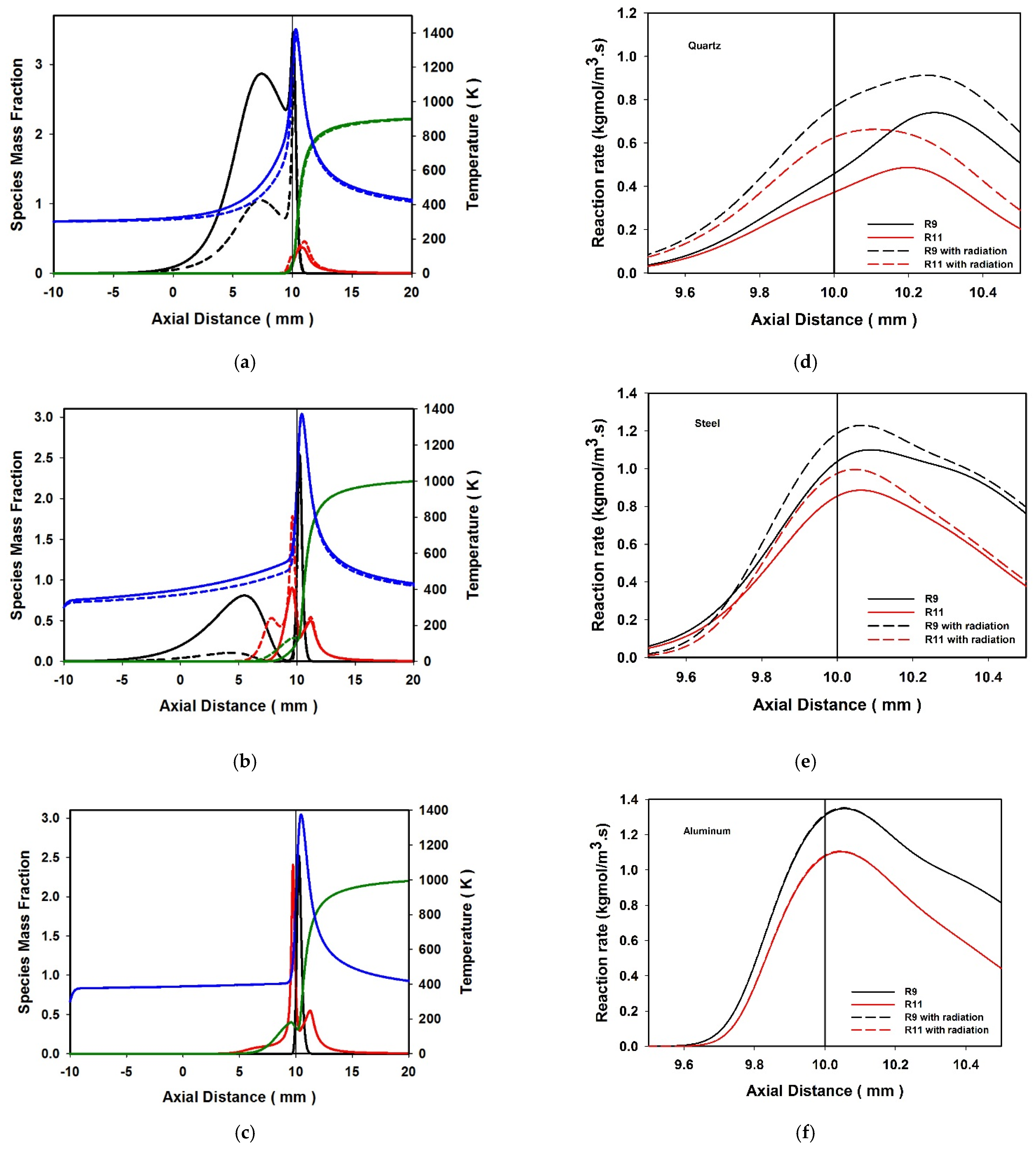
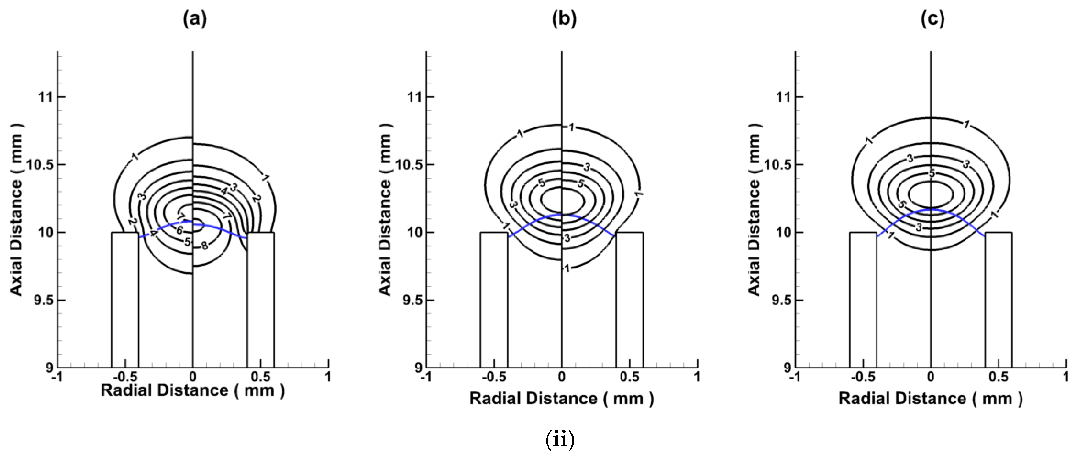
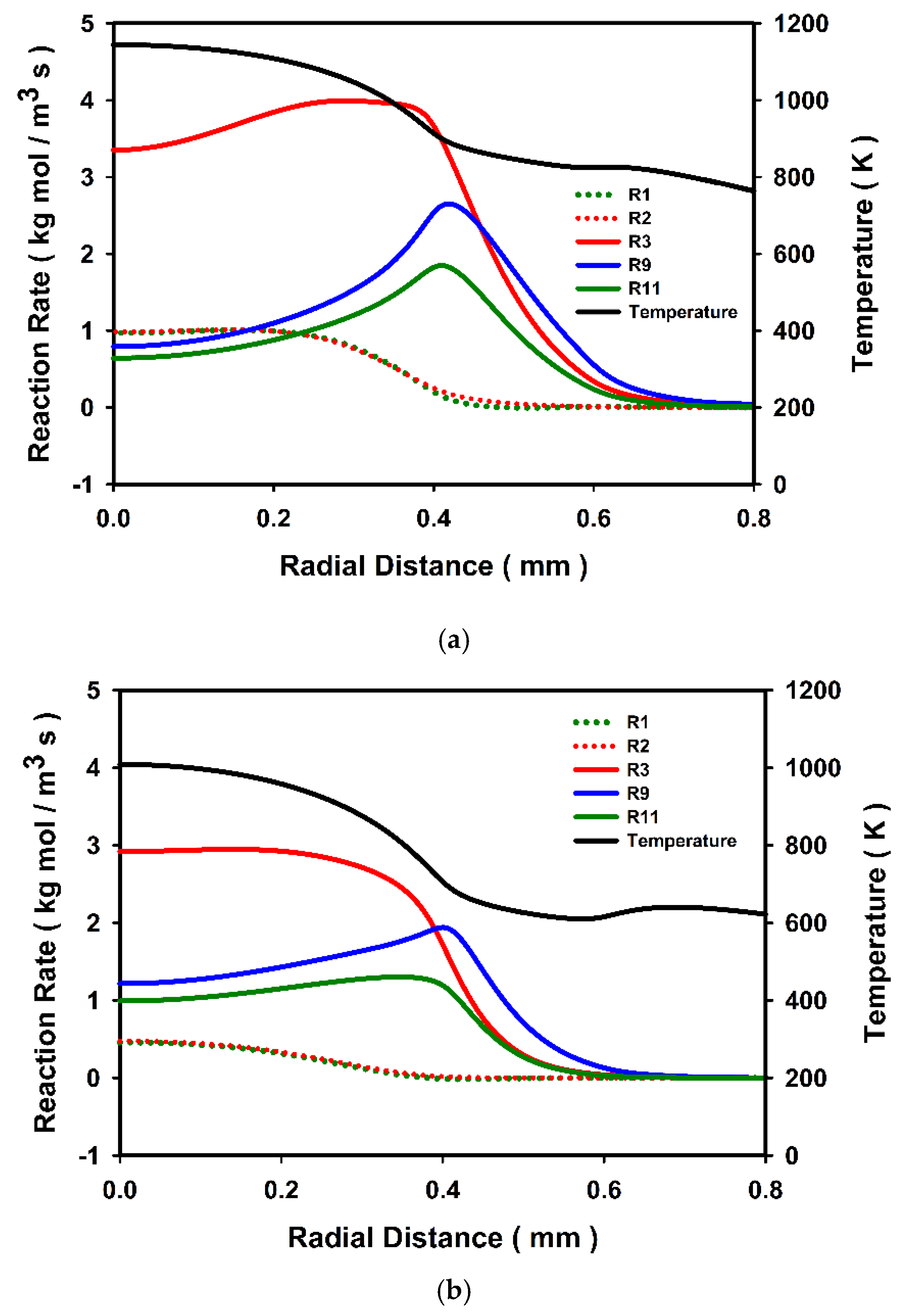
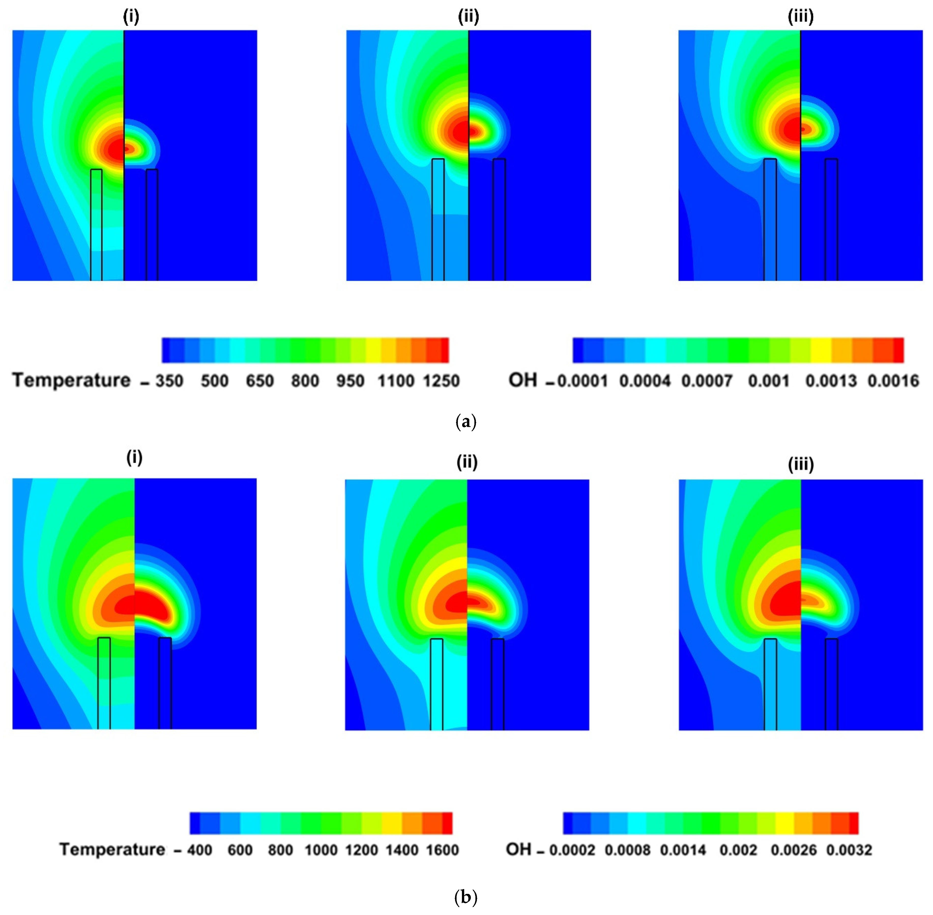
3.2. Effect of Burner Wall Material and Thermal Radiation on Flame Structure

In order to investigate the effect of burner wall material as well as thermal radiation on micro flame structure, axial distribution of static temperature along with the mass fractions of H, HO2, and O2 are plotted along the axis as shown in Figure 7a–c, respectively, for quartz, v = 0.13 m/s, steel, v = 0.14 m/s, and aluminum, v = 0.14 m/s, with and without considering radiation effects. The vertical straight line indicates the axial location of the burner exit. The computational domain is extended in the negative x-direction, such that the burner bottom is at (−10) mm along the axial (x) direction. The burner tip is at 10 mm along the axial (x) direction.
It can be noted that the variation of axial static temperature within the burner tube is parabolic, linear, and asymptotic with the x-axis, respectively, for quartz, steel, and aluminum burners. There is not much change observed for the temperature distribution downstream of the flame region. Radiation effects are predominant within the burner length for quartz burner. As the thermal conductivity of the burner wall increases, a greater amount of heat is lost from the burner tip, which in turn produces a uniform temperature distribution along the wall. Thus, the slope of the curve representing the static temperature distribution along the axis is lesser for aluminum and steel burners compared to that of quartz.
HO2 radical is responsible for high HRR within the flame standoff region [3,10]. At extinction, the flame is stabilized just above the burner port, and the flame standoff distance becomes minimal. HO2 radical concentration gives additional information about the heat release and heat transfer from the flame region. Therefore, a comparison of HO2 radical concentration along the axis is presented for all three burner cases. From Figure 7a–c, it can be identified that there is a significant amount of HO2 radicals present inside the burner in all the cases. This is an indication of the occurrence of HO2 production reaction H + O2 (+M) => HO2 (+M) inside the burner, close to the burner tip. At near extinction velocities, the upstream gets preheated, causing the H radicals to be transferred into the burner because of diffusional transport [18]. The variation of H radical concentration with burner wall material is notable. Higher flame temperatures are observed for quartz followed by steel and aluminum burners for the same fuel inlet velocity. A higher temperature of the flame due to burner material affects the production of ‘H’ radical as it is a high-temperature reaction and favored by the high temperature in the reaction zone. The inclusion of radiation results in additional heat loss from the flame region and reduces the H radical production. The mass fraction contours of O2 in Figure 7 show that O2 also diffuses into the burner at low-velocity conditions. The concentration of O2 species along the axis for the three cases with the same jet velocity indicates the rate of its depletion and combustion completeness. Interestingly, more O2 is entrained into the burner tube once the fuel jet velocity is reduced. These results in oxidation reactions to occur inside the burner close to the tip at near extinction velocities. In order to verify this, HO2 production reactions, R9 and R11 are plotted along the axis for quartz, steel, and aluminum burners, respectively, in Figure 7d–f, with and without considering radiation effects. These graphs show that the reactions H + O2 (+M) => HO2 (+M) (R9) and HO2 + H => OH + OH (R11) are present inside the burner for all the cases. It can be inferred from the graphs that the reaction rate increases with an increase in thermal conductivity. The amount of oxygen entrained into the burner port is minimum for quartz burner whereas more oxygen is entrained into the burner port when steel and aluminum burner is adopted. The mass fraction profile for O2 decreases smoothly to zero in the case of quartz burner. However, for steel and aluminum, the O2 mass fraction profile reaches a minimum value just upstream of the flame region and then increases slightly before it further decreases to zero along the axis.
The reaction rates show significant variation with and without radiation, in the case of quartz burner, as seen in Figure 7d. When radiation is considered, the burner wall at the tip gets heated. The gases in the burner near the burner tip are heated because of the heat transfer from the burner wall at the tip. This causes an increase in reaction rate inside the burner, near the burner tip in the case of the quartz burner. However, when thermal conductivity is increased, the radiation effect on the reactions inside the burner becomes less prominent since the heat from the burner tip diffuses quickly without transferring much heat to the gas mixture inside the burner. For the case of aluminum, the variation in reaction with and without radiation becomes insignificant, as shown in Figure 7f.
In order to visualize the flame structure completely, two dimensional contours of HO2 mass fraction along with velocity vector and stoichiometric mixture fraction (blue), species mass fractions of H (black), are plotted in Figure 8i,ii, respectively, for flames stabilized on (a) quartz, v = 0.13 m/s (b) steel, v = 0.14 m/s and (c) aluminum, v = 0.14 m/s. Stoichiometric mixture fraction [44], fstoic locates the peak reaction zone where fuel and oxidizer mix in stoichiometric proportions. The value of fstoic is calculated as 0.02852. In Figure 8, the contours to the right side of the axis represent no-radiation cases, and the left side depicts the cases with radiation. The contour lines for H are labeled from 1 to ‘n’ in the increasing order of contour values. The contour values of H vary from 2 × 10⁻⁵ with a Δ = 4 × 10⁻⁵. The velocity field around the flame gets induced due to buoyancy. However, the nearly spherical shape of the flame is obtained because the size of the flame is minimal. The velocity vectors are shown in Figure 8i. It can be observed that the induced velocity is almost similar for all the burners.
The HO2 mass fraction contours show that there is a significant presence of HO2 inside the burner in the case of steel and aluminum (Figure 8(ib,c), respectively). Figure 8a shows that the HO2 radicals inside the quartz burner are less significant, and this species is mainly concentrated at the burner tip. As radiation effects are included, there is an increase in HO2 mass fraction in the flame standoff and as well as inside the burner. For steel and aluminum burners, a greater amount of HO2 is observed at the flame standoff region, even for the no-radiation case. However, the axial extent of HO2 mass fraction is reduced once the radiation is considered. For steel and aluminum burners, HO2 mass fraction contours surround the flame region. These results corroborate the earlier findings in Figure 7.
Figure 8ii identifies that the stoichiometric mixture fraction line shifts axially outward for steel and aluminum burners compared to that of quartz. This indicates the occurrence of more intense burning slightly downstream of the domain in the case of steel and aluminum than quartz. Hence, increased flame height is observed for flames stabilized on steel or aluminum burners. It can be noted from Figure 8(iia) that H radical contours are extended more into the burner tube for quartz compared to that of steel or aluminum. Additionally, there is a significant concentration of H radicals at the burner top surface for the quartz burner case. For steel and aluminum, H radicals are concentrated at the flame region and not very near to burner wall surface. The maximum value of H mass fraction is found to be at the flame region irrespective of the burner tube material. The maximum value of H mass fraction decreases as the radiation effects are included in the present model.
To further illustrate the flame structure near extinction, contours of O2 and HO2 are plotted for (a) quartz, v = 0.13 m/s, (b) steel, v = 0.14 m/s and (c) aluminum, v = 0.14 m/s as shown in Figure 9. The O2 mass fraction contours indicate that the oxygen mass fraction decreases gradually to zero at the flame region for the quartz burner. However, there exists an axial elliptical region of lower O2 mass fraction for steel and aluminum burners. Beyond this region, the mass fraction of O2 decreases gradually to zero inside the burner port. Corresponding to this region of lower oxygen mass fraction, there is an elliptical region of higher H2O mass fraction for steel and aluminum burners, as shown. The mass fraction of H2O gradually increases, and the maximum is observed inside the burner tube for the quartz burner.
Some of the important reactions were analyzed to explore the chemical structure formed in the flame standoff region. Important reactions were selected based on their net reaction rate, as shown in Table 1. The reaction rates in the case of steel and aluminum burners are slightly higher than that of quartz burner. Even then, a higher flame temperature was observed for quartz burner. The lower heat conductivity of quartz burner compared to the other two causes a higher flame temperature. Since the present study deals with near extinction flames, the conductive heat loss through the burner wall can cause reduction of the temperature. Figure 10 shows the radial profiles of selected reactions along with the static temperature distribution at an axial distance of H/16 (H, the flame height) above the burner top surface. Plots were made for (a) quartz, v = 0.13 m/s, (b) steel, v = 0.14 m/s and (c) aluminum, v = 0.14 m/s with radiation effects. Figure 10d cross compares the rate of reactions R3 and R9 for three different burners. Reaction R3 is the major heat-releasing reaction (HO2 production). A comparison clearly shows a higher flame temperature for Quartz material at a given fuel jet velocity.
Similarly, Reaction R9 is another HO2 production reaction. This reaction is cross-compared as HO2 has a higher heat release rate in the flame standoff region. HO2 production rate, temperature, and rate of reaction are higher for quartz burner.
The radial profiles along the flame standoff region indicate that static temperature drops at a higher rate up to the burner wall in the radial direction and then drops at a lesser rate for all three burners. However, the flame standoff region is observed to be at a higher temperature for quartz than steel or aluminum burner.
The reactions R1 and R2 have their respective maximum value at the axis and decrease to zero along the radial direction. The rates of reactions R1 and R2 are maximum for quartz burner and decrease for steel or aluminum burners. The reaction profiles of R1 and R2 become broader as the thermal conductivity of the burner wall decreases.
The reaction profile of R3 is broader for quartz as compared to both steel and aluminum. At the axis, the rate of reaction for R3 is maximum for quartz burner and decreases as steel or aluminum burner is adopted. In the flame region, OH radicals are produced through reaction R9 followed by R11 [18]. H atoms are oxidized to form HO2 radicals (R9), which in turn are consumed to produce OH radicals through reaction R11. For quartz burner, rate of reaction, R9 increases to a maximum value at burner wall in radial location and further reduces to zero.
For steel and aluminum burners, the rate of R9 reaction is maximum at the axial location and decreases to zero while moving radially outwards. Reaction R11 also follows a similar trend in variation to that of R9. However, the rate of R11 is always lesser than that of R9.
In order to visualize the flame shape and the temperature distribution effectively, the contours of static temperature (left-hand side of axis) and OH mass fraction (right side) were plotted for three burners, as shown in Figure 11. Plots were made for near extinction conditions (Figure 11a) and at a fuel inlet velocity, v = 0.25 m/s (Figure 11b). The flames always stabilize near the burner wall surface for quartz as compared to steel or aluminum burners. For quartz, the burner wall is at a higher temperature than steel and aluminum.
The effect of burner wall material on OH mass fraction is negligible for near extinction conditions. However, at higher fuel flow velocities (v = 0.25 m/s), the OH mass fraction changes significantly with a change in burner wall material, as shown in Figure 11b. Additionally, OH mass fraction contours are extended towards the burner top surface for quartz, whereas the amount of OH present near the burner wall is reduced for the case of steel and aluminum burners. Even though the overall flame shapes appear the same for all three materials, the flame structure near the burner tip is significantly different. There is an axially elongated temperature field downstream for the case of quartz burner.

3.3. Effect of Burner Wall Thickness on Flame Characteristics and Structure

In order to investigate the effect of burner wall thickness on diffusion flame characteristics and structure, simulations were performed using burners with wall thicknesses of t = 0.1, 0.2, and 0.3 mm. Burner diameter, d = 0.8 mm, and the length, l = 10 mm, were kept constant for all three cases.
Variation of non-dimensional flame heights along with the maximum flame temperature with the wall thickness of the burner tube is presented in Figure 12. It can be observed that the flame height decreases by ~24% as the wall thickness is reduced from 0.3 to 0.1 mm. However, there is a slight increase in the maximum flame temperature (1.4%) with a decrease in the wall thickness.
In order to investigate the effect of burner wall thickness on the flame structure at small scales, axial distribution of species mass fractions along with the burner wall centerline temperature for burners of thicknesses (a) t = 0.1, (b) t = 0.2, and (c) t = 0.3 mm were plotted as shown in Figure 13.
It can be inferred from Figure 13a that along the axial direction, there is an inward shift of peak H radical distribution with a reduction in wall thickness. Higher fractions of H radicals are found to be present within the burner as the wall thickness of the burner tube is reduced. High temperatures dominate the formation of H radical. Therefore, the concentration and distribution of H radical will indicate the temperature distribution in the flame region. Figure 13b presents the variation of HO2 mass fraction along the axis. It is observed that the HO2 mass fraction in the flame region increases with an increase in burner wall thickness. The amount of HO2 present within the burner tube increases with an increase in the wall thickness of the burner. It is to be noted that there is a drastic increase in HO2 mass fraction near the flame base with an increase in burner wall thickness.
In order to examine the effect of wall thickness on burner wall heat recirculation, static temperature distribution along the burner wall centerline is plotted for burners of thicknesses, t = 0.1, 0.2, and 0.3 mm, as shown in Figure 13c. It can be noted that the temperature at the burner top surface is the highest for t = 0.1 mm and decreases with an increase in wall thickness. At the middle section of the burner, the temperature is observed to be the minimum for t = 0.1 mm and increases with an increase in wall thickness. However, at the burner base, the effect of wall thickness on heat recirculation is minimal.
To further investigate the effect of wall thickness on flame shape and geometry, static temperature (left side) and OH mass fraction (right side) contours are plotted for quartz burner with radiation at a fuel inlet velocity, v = 0.13 m/s, in Figure 14. Variation in wall thickness appears to have a negligible effect on the overall flame shape and flame temperature distribution. However, the temperature field in and around the burner tip shows significant variation, as observed in Figure 14. As the burner thickness increases, more heat gets transferred through the burner bottom, reducing the heat recirculation to the fresh incoming mixture through the burner tube. This reduced heat recirculation through the tube walls reduces the peak flame temperature.
On the other hand, when the wall thickness reduces, heat loss to the surrounding from the burner wall reduces, therefore the recirculation effect increases. The presence of OH mass fraction can be observed near the burner tip for the t = 0.1 mm case due to higher flame temperature indicating the reaction continues in the vicinity of the tube walls. For higher wall thickness cases, the OH mass fraction near the burner wall decreases.

4. Conclusions

The effect of burner wall material and thermal radiation on flame characteristics and flame structure is investigated numerically by adopting three different burner materials with thermal conductivity varying from 1 to 200 W/m K (quartz, steel, and aluminum). The effect of burner wall thickness on flame temperature, flame height, and flame structure is also studied. The combustion chemistry is modeled with a detailed reaction mechanism having 10 species and 21 reactions.
The present computational study showed that flames stabilize on the quartz burner at lower fuel jet velocities than that of steel or aluminum burners. These results confirmed that the burner wall thermal conductivity and heat recirculation through burner walls play a significant role in flame stabilization. However, the extinction limit varies from 0.125 to 0.13 m/s for quartz burner as thermal radiation effects are included. The flame temperature is found to be maximum for quartz burner and decreases with an increase in thermal conductivity of wall material. Flame length is found to be increasing with an increase in the thermal conductivity of the burner wall. From a practical point of view, quartz burner can be a better choice for lower fuel velocity micro diffusion flame applications.
Although the effect of thermal radiation on flame characteristics is insignificant, the impact on the flame’s chemical structure, including the distribution of radicals in the flame region, is significant. The burner tip is substantially heated for quartz burner. The flame shape is almost identical, while the reaction zone structure near the burner port is quite different, and it depends upon the wall material. The effect of burner wall thickness on maximum flame temperature is minimal, affecting the flame height significantly. The variation in burner wall thickness affects H and HO2 radical distribution at the flame region. Although the variation in wall thickness has the least effect on the overall flame shape and temperature distribution, the structure near the burner port differs.
The variation in flame characteristics and flame structure is significant for steel instead of quartz burner, and the effect is minimal when aluminum is used instead of steel.

Author Contributions

Conceptualization, R.K.V. and J.E.V.; methodology, R.K.V. and J.E.V.; software, R.K.V., A.M. (Akram Mohammad); validation, J.E.V. and A.M. (Aravind Muraleedharan); formal analysis, J.E.V. and A.M. (Aravind Muraleedharan); investigation, J.E.V. and A.M. (Aravind Muraleedharan); resources, A.M. (Akram Mohammad) and R.K.V.; data curation, J.E.V. and A.M. (Aravind Muraleedharan); writing—original draft preparation, A.M. (Aravind Muraleedharan) and J.E.V.; writing—review and editing, R.K.V., A.M. (Akram Mohammad) and S.K.; supervision, R.K.V. and S.K. All authors have read and agreed to the published version of the manuscript.

Funding

This research received no external funding.

Data Availability Statement

Not Applicable.

Acknowledgments

The authors would like to acknowledge the administration of Amrita Vishwa Vidyapeetham and for a part of computations were performed on the Aziz Supercomputer at King Abdulaziz University’s High-Performance Computing Center (http://hpc.kau.edu.sa). The authors acknowledge the computer time and technical support provided by the center.

Conflicts of Interest

The authors declare no conflict of interest.

References

  1. Fernandez-Pello, A.C. Micropower generation using combustion: Issues and approaches. Proc. Combust. Inst. 2002, 29, 883–899. [Google Scholar] [CrossRef] [Green Version]
  2. Ju, Y.; Maruta, K. Microscale combustion: Technology development and fundamental research. Prog. Energy Combust. Sci. 2011, 37, 669–715. [Google Scholar] [CrossRef]
  3. Chou, S.K.; Yang, W.M.; Chua, K.J.; Li, J.; Zhang, K.L. Development of micro power generators—A review. Appl. Energy 2011, 88, 1–16. [Google Scholar] [CrossRef]
  4. Walther, D.C.; Ahn, J. Advances and challenges in the development of power-generation systems at small scales. Prog. Energy Combust. Sci. 2011, 37, 583–610. [Google Scholar] [CrossRef]
  5. Reddy, K.S.; Pavan, K.M.S.; Yadav, S. Numerical study of micro combustor along with recirculation cap over stability of flame. In Proceedings of the 2021 IEEE 6th International Conference for Convergence in Technology (I2CT), Mumbai, India, 2–4 April 2021; pp. 1–3. [Google Scholar]
  6. Chakravarthy, C.G.G.; Krithik, M.A.; Siddhartha, G.; Dineshkumar, L. Numerical Study on Stabilization of Flame Inside Micro-Combustor; AIP Publishing LLC: Maharashtra, India, 2019; p. 020058. [Google Scholar]
  7. Shukla, P.R.; Skea, J.; Calvo Buendia, E.; Masson-Delmotte, V.; Pörtner, H.O.; Roberts, D.C.; Zhai, P.; Slade, R.; Connors, S.; Van Diemen, R. Climate Change and Land: An IPCC Special Report on Climate Change, Desertification, Land Degradation, Sustainable Land Management, Food Security, and Greenhouse Gas Fluxes in Terrestrial Ecosystems; IPCC: Geneva, Switzerland, 2019. [Google Scholar]
  8. Ban, H.; Venkatesh, S.; Saito, K. Convection-diffusion controlled laminar micro flames. Previews Heat Mass Transf. 1995, 2, 126. [Google Scholar] [CrossRef]
  9. Matta, L.M.; Neumeier, Y.; Lemon, B.; Zinn, B.T. Characteristics of microscale diffusion flames. Proc. Combust. Inst. 2002, 29, 933–939. [Google Scholar] [CrossRef]
  10. Chen, C.P.; Chao, Y.C.; Cheng, T.S.; Chen, G.B.; Wu, C.Y. Structure and stabilization mechanism of a microjet methane diffusion flame near extinction. Proc. Combust. Inst. 2007, 31, 3301–3308. [Google Scholar] [CrossRef]
  11. Cheng, T.S.; Chao, Y.C.; Chen, C.P.; Wu, C.Y. Further analysis of chemical kinetic structure of a standoff microjet methane diffusion flame near extinction. Combust. Flame 2008, 152, 461–467. [Google Scholar] [CrossRef]
  12. Nakamura, Y.; Yamashita, H.; Saito, K. A numerical study on extinction behaviour of laminar micro-diffusion flames. Combust. Theory Model. 2006, 10, 927–938. [Google Scholar] [CrossRef]
  13. Kuwana, K.; Tagami, N.; Mizuno, S.; Ida, T. Extinction of laminar jet diffusion microflames. Proc. Combust. Inst. 2009, 32, 3115–3121. [Google Scholar] [CrossRef]
  14. Cheng, T.S.; Chao, Y.C.; Wu, C.Y.; Li, Y.H.; Nakamura, Y.; Lee, K.Y.; Yuan, T.; Leu, T.S. Experimental and numerical investigation of microscale hydrogen diffusion flames. Proc. Combust. Inst. 2005, 30, 2489–2497. [Google Scholar] [CrossRef]
  15. Cheng, T.-S.; Wu, C.Y.; Chen, C.P.; Li, Y.H.; Chao, Y.C.; Yuan, T.; Leu, T.S. Detailed measurement and assessment of laminar hydrogen jet diffusion flames. Combust. Flame 2006, 146, 268–282. [Google Scholar] [CrossRef]
  16. Darabiha, N. Transient behaviour of laminar counterflow hydrogen-air diffusion flames with complex chemistry. Combust. Sci. Technol. 1992, 86, 163–181. [Google Scholar] [CrossRef]
  17. Cheng, T.S.; Chen, C.P.; Chen, C.S.; Li, Y.H.; Wu, C.Y.; Chao, Y.C. Characteristics of microjet methane diffusion flames. Combust. Theory Model. 2006, 10, 861–881. [Google Scholar] [CrossRef]
  18. Hossain, A.; Nakamura, Y. Thermal and chemical structures formed in the micro burner of miniaturized hydrogen-air jet flames. Proc. Combust. Inst. 2015, 35, 3413–3420. [Google Scholar] [CrossRef]
  19. Fujiwara, K.; Nakamura, Y. Experimental study on the unique stability mechanism via miniaturization of jet diffusion flames (microflame) by utilizing preheated air system. Combust. Flame 2013, 160, 1373–1380. [Google Scholar] [CrossRef] [Green Version]
  20. Gao, J.; Hossain, A.; Nakamura, Y. Flame base structures of micro-jet hydrogen/methane diffusion flames. Proc. Combust. Inst. 2017, 36, 4209–4216. [Google Scholar] [CrossRef]
  21. Li, X.; Zhang, J.; Yang, H.; Jiang, L.; Wang, X.; Zhao, D. Combustion characteristics of non-premixed methane micro-jet flame in coflow air and thermal interaction between flame and micro tube. Appl. Therm. Eng. 2017, 112, 296–303. [Google Scholar] [CrossRef]
  22. Zhang, J.; Li, X.; Yang, H.; Jiang, L.; Wang, X.; Zhao, D. Study on the combustion characteristics of non-premixed hydrogen micro-jet flame and the thermal interaction with solid micro tube. Int. J. Hydrog. Energy 2017, 42, 3853–3862. [Google Scholar] [CrossRef]
  23. Norton, D.G.; Vlachos, D.G. A CFD study of propane/air microflame stability. Combust. Flame 2004, 138, 97–107. [Google Scholar] [CrossRef]
  24. Gauthier, G.P.; Watson, G.M.G.; Bergthorson, J.M. Burning rates and temperatures of flames in excess-enthalpy burners: A numerical study of flame propagation in small heat-recirculating tubes. Combust. Flame 2014, 161, 2348–2360. [Google Scholar] [CrossRef]
  25. Gao, J.; Hossain, A.; Matsuoka, T.; Nakamura, Y. A numerical study on heat-recirculation assisted combustion for small scale jet diffusion flames at near-extinction condition. Combust. Flame 2017, 178, 182–194. [Google Scholar] [CrossRef]
  26. Maruta, K. Micro and mesoscale combustion. Proc. Combust. Inst. 2011, 33, 125–150. [Google Scholar] [CrossRef]
  27. Nakamura, Y.; Gao, J.; Matsuoka, T. Progress in small-scale combustion. J. Therm. Sci. Technol. 2017, 12, JTST0001. [Google Scholar] [CrossRef] [Green Version]
  28. Muraleedharan, A.; Jithin, E.V.; Aravind, B.; Kumar, S.; Velamati, R.K. Combustion characteristics of syngas laminar microjet diffusion flames. J. Taiwan Inst. Chem. Eng. 2020, 115, 47–59. [Google Scholar] [CrossRef]
  29. Resende, P.R.; Ayoobi, M.; Afonso, A.M. Numerical investigations of micro-scale diffusion combustion: A brief review. Appl. Sci. 2019, 9, 3356. [Google Scholar] [CrossRef] [Green Version]
  30. Liu, L.; Zhao, M.; Chen, Y.K.; Fan, A.W.; Li, D. A numerical investigation in buoyancy effects on micro jet diffusion flame. J. Cent. South Univ. 2020, 27, 867–875. [Google Scholar] [CrossRef]
  31. Zhao, M.; Fan, A. Buoyancy effects on hydrogen diffusion flames confined in a small tube. Int. J. Hydrog. Energy 2020, 45, 19926–19935. [Google Scholar] [CrossRef]
  32. Zhao, M.; Liu, L.; Fan, A. Comparison of combustion efficiency of micro hydrogen jet flames confined in cylindrical tubes of different diameters. Chem. Eng. Process. Process Intensif. 2020, 153, 108000. [Google Scholar] [CrossRef]
  33. Hong, J.; Zhao, M.; Liu, L.; Shi, Q.; Xiao, X.; Fan, A. Improvement of the Combustion Completeness of Hydrogen Jet Flames within a Mesoscale Tube under Zero Gravity. Energies 2021, 14, 4552. [Google Scholar] [CrossRef]
  34. Li, J.; Zhao, Z.; Kazakov, A.; Dryer, F.L. An updated comprehensive kinetic model of hydrogen combustion. Int. J. Chem. Kinet. 2004, 36, 566–575. [Google Scholar] [CrossRef]
  35. Raithby, G.D.; Chui, E.H. A finite-volume method for predicting a radiant heat transfer in enclosures with participating media. ASME Trans. J. Heat Transf. 1990, 112, 415–423. [Google Scholar] [CrossRef]
  36. Fluent, A. 14.5. 0 Documentation, ANSYS® Academic Research, Release 14.5.0; ANSYS. Inc.: Canonsburg, PA, USA, 2011. [Google Scholar]
  37. Nair, A.; Kishore, V.R.; Kumar, S. Dynamics of Premixed Hydrogen-Air Flames in Microchannels with a Wall Temperature Gradient. Combust. Sci. Technol. 2015, 187, 1620–1637. [Google Scholar] [CrossRef]
  38. Nair, A.; Velamati, R.K.; Kumar, S. Effect of CO2/N2 dilution on laminar burning velocity of liquid petroleum gas-air mixtures at elevated temperatures. Energy 2016, 100, 145–153. [Google Scholar] [CrossRef]
  39. Kang, X.; Gollan, R.J.; Jacobs, P.A.; Veeraragavan, A. Suppression of instabilities in a premixed methane–air flame in a narrow channel via hydrogen/carbon monoxide addition. Combust. Flame 2016, 173, 266–275. [Google Scholar] [CrossRef]
  40. Singh, A.P.; RatnaKishore, V.; Minaev, S.; Kumar, S. Numerical investigations of unsteady flame propagation in stepped microtubes. RSC Adv. 2015, 5, 100879–100890. [Google Scholar] [CrossRef]
  41. Norton, D.G.; Vlachos, D.G. Combustion characteristics and flame stability at the microscale: A CFD study of premixed methane/air mixtures. Chem. Eng. Sci. 2003, 58, 4871–4882. [Google Scholar] [CrossRef]
  42. Roper, F.G. The prediction of laminar jet diffusion flame sizes: Part I. Theoretical model. Combust. Flame 1977, 29, 219–226. [Google Scholar] [CrossRef]
  43. Roper, F.G.; Smith, C.; Cunningham, A.C. The prediction of laminar jet diffusion flame sizes: Part II. Experimental verification. Combust. Flame 1977, 29, 227–234. [Google Scholar] [CrossRef]
  44. Turns, S.R. An Introduction to Combustion; McGraw-Hill New York: New York, NY, USA, 1996; Volume 287. [Google Scholar]
Figure 1. (a) Schematic view of the computational domain (b) computational grid used in present work.
Energies 14 08266 g001
Figure 2. Comparison of OH mass fraction and temperature profiles along the axis for non-adapted and adapted grid (data corresponding to alternate grid points are presented for adapted grid).
Energies 14 08266 g002
Figure 3. Comparison of maximum flame temperatures with and without considering radiation effects for flames stabilized on (a) quartz, (b) steel, (c) aluminum burners.
Energies 14 08266 g003aEnergies 14 08266 g003b
Figure 4. Variation of maximum flame temperature with inlet fuel jet velocity for quartz, steel, and aluminum burners (radiation effects are included).
Energies 14 08266 g004
Figure 5. (a) Comparison of computed flame heights for quartz, with radiation effects, based on (i) maximum OH mass fraction, (ii) maximum heat release rate, (iii) stoichiometric mixture fraction, with corresponding locations of maximum flame temperature. (b) Comparison of theoretical and numerical flame heights.
Energies 14 08266 g005
Figure 6. Variation of non-dimensional flame heights with fuel inlet velocity for quartz, steel, and aluminum burners.
Energies 14 08266 g006
Figure 7. Axial distribution of static temperature, selected species mass fractions (ac) and reaction rates for R9 and R11 (df) along the axis for (a,d) quartz, v = 0.13 m/s, (b,e) steel, v = 0.14 m/s and (c,f) aluminum, v = 0.14 m/s.
Energies 14 08266 g007aEnergies 14 08266 g007b
Figure 8. (i) Contours of HO2 mass fraction along with velocity vectors. (ii) Mass fraction of H and stoichiometric mixture fraction, (a) quartz v = 0.13 m/s, (b) steel, v = 0.14 m/s and (c) aluminum, v = 0.14 m/s; left side—with radiation effects; right side—without radiation effects.
Energies 14 08266 g008aEnergies 14 08266 g008b
Figure 9. Contours of mass fractions of O2 and H2O, (a) quartz, v = 0.13 m/s, (b) steel, v = 0.14 m/s, (c) aluminum, v = 0.14 m/s (radiation effects are included).
Energies 14 08266 g009
Figure 10. Radial profiles of static temperature along with net rate of selected reactions for (a) quartz, v = 0.13 m/s, (b) steel, v = 0.14 m/s and (c) aluminum, v = 0.14 m/s, (d) cross comparison of R3, R9 for quartz, steel, and aluminum.
Energies 14 08266 g010aEnergies 14 08266 g010b
Figure 11. (a). Static temperature (left hand side) and OH mass fraction contours (right side) near extinction (i) quartz, v = 0.13 m/s, (ii) steel, v = 0.14 m/s and (iii) aluminum, v = 0.14 m/s. (b). Static temperature (left hand side) and OH mass fraction contours (right side) for fuel inlet velocity, v = 0.25 m/s (i) quartz, (ii) steel, and (iii) aluminum.
Energies 14 08266 g011
Figure 12. Comparison of flame heights and maximum flame temperature with burner tube thickness. The burner wall material is quartz, and the fuel jet velocity = 0.14 m/s. Radiation effects are included.
Energies 14 08266 g012
Figure 13. Axial distribution of the mass fraction of (a) H, (b) HO2, and (c) temperature distribution along the burner wall centerline for burners having thicknesses t = 0.1, 0.2, 0.3 mm. The burner wall material is quartz, and the fuel jet velocity, v = 0.14 m/s. Radiation effects are also included.
Energies 14 08266 g013
Figure 14. Static temperature (left hand side) and OH mass fraction contours (right side) near extinction for quartz burner, with radiation effects and v = 0.13 m/s (a) t = 0.1 mm, (b) t = 0.2 mm, and (c) t = 0.3 mm.
Energies 14 08266 g014
Table 1. Important reactions in H2—O2 combustion.
NumberReactionMaximum Reaction Rate (kg mol/m3s)
Burner MaterialQuartzSteelAluminum
R1H + O2 → O + OH3.0293.2173.152
R2O + H2 → H + OH2.4012.5962.553
R3H2 + OH → H2O + H7.0897.4647.542
R9H + O2 (+M) → HO2 (+M)3.7193.0842.341
R11HO2 + H → OH + OH2.4011.3641.364
Publisher’s Note: MDPI stays neutral with regard to jurisdictional claims in published maps and institutional affiliations.

