
Estimation of the Compressive Strength of Corrugated Cardboard Boxes with Various Perforations


1
Department of Biosystems Engineering, Poznan University of Life Sciences, Wojska Polskiego 50, 60-627 Poznań, Poland
2
Institute of Structural Analysis, Poznan University of Technology, Piotrowo Street 5, 60-965 Poznań, Poland
3
Institute of Applied Mechanics, Poznan University of Technology, Jana Pawła II Street 24, 60-965 Poznań, Poland
*
Author to whom correspondence should be addressed.
Energies 2021, 14(4), 1095; https://0-doi-org.brum.beds.ac.uk/10.3390/en14041095
Submission received: 31 December 2020
/
Revised: 14 February 2021
/
Accepted: 18 February 2021
/
Published: 19 February 2021
(This article belongs to the Special Issue Strain Energy in Composite Structures)
Abstract
:This paper presents a modified analytical formula for estimating the static top-to-bottom compressive strength of corrugated board packaging with different perforations. The analytical framework is based here on Heimerl’s assumption with an extension from a single panel to a full box, enhanced with a numerically calculated critical load. In the proposed method, the torsional and shear stiffness of corrugated cardboard, as well as the panel depth-to-width ratio is implemented in the finite element model used for buckling analysis. The new approach is compared with the successful though the simplified McKee formula and is also verified with the experimental results of various packaging designs made of corrugated cardboard. The obtained results indicate that for boxes containing specific perforations, simplified methods give much larger estimation error than the analytical–numerical approach proposed in the article. To the best knowledge of the authors, the influence of the perforations has never been considered before in the analytical or analytical–numerical approach for estimation of the compressive strength of boxes made of corrugated paperboard. The novelty of this paper is to adopt the method presented to include perforation influence on the box compressive strength estimation.
1. Introduction
Shelf-ready packaging (SRP) is playing an increasingly important role in the modern industry, including the supply and sales market. The main task of SRP is to ensure safe transportation and storage of products in packaging and then putting them directly on shelves without unpacking individual goods. Application of SRP leads to the reduction of costs related to the work of employees and helps to save time. Therefore, tedious unpacking of products on the shelf has been reduced to a few seconds. The SRPs are made of corrugated cardboard with different perforations, which enable easy separation of the lower part of the packaging, called the tray, and the upper part of the packaging, called the cover. On the other hand, perforations can significantly influence the mechanical strength of boxes made of corrugated paperboards [1]. It reduces the integrity of the wall. Thus, the final compression strength of the box would also decrease. In this paper, the strength of boxes with perforations is investigated.
Performing physical experiments allows for the design and development of paperboard or corrugated cardboard boxes, to ensure their proper mechanical strength. It strictly depends on two characteristic in-plane directions of the corrugated cardboard. They are related to fluting; the first direction, called machine direction (MD), is perpendicular to the main axis of it and parallel to paperboard fiber alignment. The second one, called cross direction (CD), is parallel to the fluting.
In the packing industry, the strength of corrugated cardboard boxes can be examined by carrying out some leading physical tests. The most important, from a practical point of view, are the compressive, tensile, or bursting strength tests. The most common tests of packaging are the box compression test (BCT) and the edge crush test (ECT) for corrugated cardboard. Performing physical experiments is always time- and cost-consuming. Thus, recently, there have been some alternatives for the examination of corrugated cardboard boxes to determine their strength only by physical testing.
The first one is the prediction of compressive strength based on the formulas published in the literature. One advantage of such an approach is its simplicity, which makes it very easy and fast to apply in the real world, without the need of performing any additional experiments. Three groups of parameters used in these formulas proposed in the literature over the years can be distinguished. They include parameters of paper, board and box, respectively [2]. The most common formula in the packaging industry is the approach presented by McKee, Gander, and Wachuta in 1963 [3]. The authors formulated a relationship between the box perimeter and two corrugated board parameters, which are ECT and flexural stiffness. Two earlier approaches also took into account parameters of the paperboard [4,5]. However, one can notice that the formula proposed by McKee et al. is accurate only for some relatively simple containers. In the literature, there were some attempts for improving accuracy and extending the applicability of the analytical formulas for prediction of compressive box strength. Allerby et al. proposed a modification of constants and exponents in the original McKee’s relationship [6]. Schrampfer et al. modified the McKee’s approach, allowing to extend the applicability of the formula for a wide range of cutting methods and equipment [7]. Batelka et al. also took into account dimensions of the box [8], while Urbanik et al. included the Poisson’s ratio [9]. The constants in the original McKee’s formula was later analyzed for more complicated cases and was recently modified by Aviles et al. [10] and later by Garbowski et al. [11,12]. The compression strength of boxes made of corrugated paperboard [13] can be affected by many factors, including the moisture content of the box [14,15], the existence of openings [12,16], storage time, stacking conditions [17], and many others.
The other alternative is a purely numerical method, which may be applied to investigate box compression strength. The most popular method in engineering is the finite element method (FEM). It was applied in many problems related to the strength of corrugated boxes. They include research on transverse shear stiffness of corrugated cardboards [18,19,20,21] or buckling and post-buckling phenomena [22].
One important step in the numerical analysis of corrugated cardboards is homogenization [23,24,25,26]. It allows simplifying the analyzed models, saving time on calculations by ensuring adequate accuracy of the results. As a consequence of the homogenization process of layered materials, one can obtain a single layer described by effective properties of the composite instead of the structure of layers made of different materials. Hohe proposed a method of homogenization based on strain energy [27]. It is suitable for sandwich panels. In his approach, there is an assumption of equivalence of a representative element of the homogenized and heterogeneous elements. Buannic et al. proposed a periodic homogenization method. In this approach, an equivalent membrane and pure bending characteristic of period plates are obtained [28]. They also modified their approach for the analysis of sandwich panels to take into consideration the transfer shear effect. Biancolini obtained the stiffness properties of the sandwich panel using the energy equivalency between the considered model and the plate, and applying the FEM in the analysis of a micromechanical part of the plate [29]. In the approach presented by Abbès and Guo, the considered plate is decomposed into two beams in directions of the plate [30]. It allows calculating the torsion rigidity of the orthotropic sandwich plates. Another approach to a homogenization of composite materials may be the measurement of the effective properties based on a correctly designed or a selected set of laboratory experiments performed directly on the composite. Such a technique is applied in this study.
In the literature, one can also find investigations on the influence of creasing on the mechanical strength of corrugated paperboard. Creasing is a process, in which fold and perforation lines are manufactured. These lines reduce the strength of corrugated paperboard. In 2008, Thakkar et al. compared the results from the experiments and numerical simulations based on the FEM to investigate the influence of the creasing on the local strength of corrugated paperboard [31]. Later, Beex and Peerlings performed physical and numerical experiments related to influence of creasing and subsequent folding on the mechanical properties of the laminated paperboard [32]. Giampieri et al. [33] proposed a constitutive model for the mechanical response of creased paperboard after folding. The FEM simulations of paperboard creasing and folding useful for the packing industry and important from a practical point of view has been presented by Domaneschi et al. [34]. Awais et al. [35] and Leminena et al. [1] investigated, experimentally and numerically, the influence of the crease on the mechanical properties of the paperboard during the press forming process. However, to the best knowledge of the authors, there are no papers on the influence of perforations on the strength of the whole boxes made of corrugated cardboard.
In this paper, a modification of the analytical–numerical approach is proposed for corrugated boxes with perforations. The article verifies the influence of perforation on the compressive strength of corrugated cardboard boxes with a modified analytical formula, through a numerically aided calculation of the critical load. Furthermore, the applicability of the approach presented in [11,12,20,21] for corrugated cardboard boxes has been extended to cases of the SRPs with different perforations.
2. Materials and Methods
2.1. Ultimate Compressive Strength of a Plate
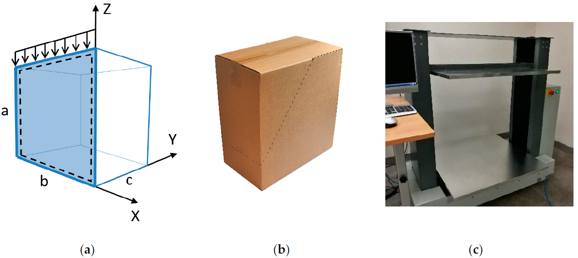
In order to compute the ultimate load on the box in a static top-to-bottom compression test, see Figure 1c, one can follow an idea presented by Heimerl [36], later used by McKee et al. [3] and recently extended by Garbowski et al. [11,12]. The basis of this approach was the calculation of the ultimate load, , of each separated panel (see Figure 1a) using the edge-loaded compressive strength of corrugated board, , and a critical load, , resulting from the buckling phenomenon:
where is a constant, is an exponent, (most often due to empirical fitting [9]), is given in N/mm, and is given in N/mm.
In Equation (1), only elastic buckling is took into account. This approach was later modified by Urbanik et al. [9,18] in order to also take into consideration the nonlinear material effects by the following:
where . If , than , which corresponds to the situation when elastic buckling is activated first, otherwise, , which corresponds to the situation when the ultimate load depends only on , namely:
In any case, the critical load for a rectangular orthotropic plate (see Figure 1a) can be assumed as [38,39,40]:
where is the critical load of the panel of dimensions (height and width, respectively), is a dimensionless buckling coefficient, which depends, e.g., on the ratio , boundary conditions applied to the plate edges, material characteristics, the buckling mode, etc.; is the bending stiffness in the MD, in Nmm, is the bending stiffness in the CD in Nmm and is the plate width in mm.
Mechanical properties of the corrugated cardboard depend on the direction (CD or MD), which is typical for fibrous materials. Therefore, the buckling coefficient can be assumed as [39]:
where is the number of half-waves in the direction of loading; is panel height in mm; is the torsional stiffness in Nmm; in Nmm; and are the effective in-plane Poisson’s ratios of the panel.
2.2. Buckling—Finite Element Method
In our case, the panel may contain various types of perforations with different positions, slopes, etc. Such a situation requires the definition of the buckling coefficient of a panel-by-panel basis, which leads to difficult and time-consuming development of analytical formulas. In such a case, the FEM is much more general because it allows determining the critical load of panels with any shape and boundary conditions, including perforations, even with complex shapes. In this study, the critical load of each panel was calculated using a three-dimensional (3D) finite element (FE) model, where all outer edges are fixed in the out-of-plane direction (see dashed lines in Figure 1a). Moreover, the bottom edge was fixed in the vertical direction. The remaining translations and all rotations were inactive. The critical load in the general case reads [40]:
where is a critical loading multiplier, i.e., the smallest eigenvalue and is a distributed load on a panel upper edge [Nmm].
In order to calculate the critical force multiplier, the typical formulation of initial buckling problem is required:
where is the global stiffness matrix of the whole panel and is an initial geometrical stress matrix of the whole panel.
By solving the eigenvector problem, it is possible to determine the pairs , where is the number of degrees of freedom, is -th eigenvalue, is -th eigenvector (post-buckling deformation mode). The minimum eigenvalue and the corresponding eigenvector define the critical load multiplier and the buckling mode of the panel. More details are provided in our previous article [12].
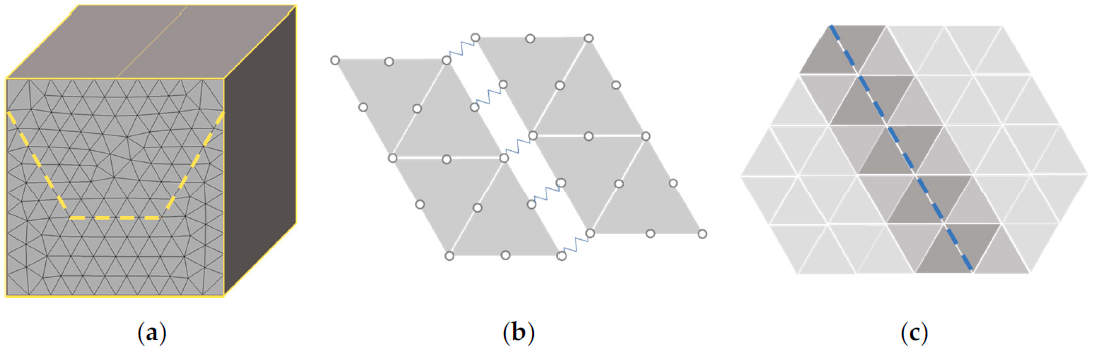
In our case, the geometry of each panel does not have to be regular, as well as the position and shape of the perforations can be chosen arbitrarily. Therefore, the triangular shell FE was adopted, see Figure 2a. Due to shear locking that can occur in FE formulation of thick plates, most of the Reissner–Mindlin FE triangular shells were developed using the assumed transverse shear strain techniques [41,42,43]. Here, the 6-noded quadratic triangle FE with a standard quadratic interpolation for the deflections and rotations, and the assumed linear transverse shear strain field was utilized. More details on the implementation of this FE, including shear locking description, can be found in our previous article [12].
2.3. Finite Element Model of a Single Panel Used in the Buckling Analysis
A new issue, not addressed in our previous article [12], concerns perforations, i.e., crease lines and partial cuts on vertical panels of the box, which is a non-trivial task when they need to be included in numerical calculations. The computational model used in our study to estimate the critical load of each panel is based on the FEM. Therefore, it is required to define the panel geometry, its boundary conditions, and the constitutive model of the corrugated boards, as well as to define the perforation lines behavior.
In order to compute the critical load of each vertical panel of the box, we used the 6-node FE described in the previous section and in [12]. An in-house routine, written in MATLAB software, was used for all analyses. Because the eigenvalue buckling prediction belongs to the linear perturbation procedures, we need to define only a linear elastic behavior. To correctly identify whole elastic material properties of corrugated cardboard, it is necessary to perform some laboratory tests, e.g., ECT, 4-point bending test, torsional stiffness test (TST), etc. In this study, we used a box strength estimation (BSE) system, which allows performing four independent tests in two main directions of corrugation and is able to identify all elastic parameters of corrugated board (www.fematsystems.pl/systems/BSE). The following parameters describe the behavior of corrugated board in the elastic range:
- —bending stiffness in the MD;
- —bending stiffness in the CD;
- —twisting bending stiffness;
- —compression stiffness in the MD;
- —compression stiffness in the CD;
- —compression stiffness in the z direction (out of plane);
- —transverse shear stiffness in the 1–3 (x–z) plane;
- —transverse shear stiffness in the 2–3 (y–z) plane.
These stiffnesses are used in the constitutive equations that describe shell FE [21]:
and are represented by the following formulas:
where:
- —effective cardboard thickness;
- —effective stiffness modulus in the MD;
- —effective stiffness modulus in the CD;
- —effective Poisson’s ratio in the 1–2 (x–y) plane;
- —effective Poisson’s ratio in the 1–2 (x–y) plane,
- —effective shear modulus in 1–2 (x–y) plane,
- —effective transverse shear modulus in the 1–3 (x–z) plane,
- —effective transverse shear modulus in the 2–3 (y–z) plane.
Having the geometry of all panels, the adopted boundary conditions and the corrugated board constitutive model defined above, all that remains is to define the behavior of perforation lines. In order to include the mechanical properties of perforations in the numerical model, two techniques are used here, namely: (a) spring connection between the parts separated by perforation, see Figure 2b, and (b) thickness reduction of the elements adjacent to the perfection, see Figure 2c. The first technique is to divide the panel with the perforation line, duplicate the mesh nodes, and add spring joints at each of the 6 degrees of freedom at each duplicated node. The second technique is to search for all elements adjacent to the perforation line, sort them by the number of nodes lying on the perforation line, and reduce the thickness of these elements (due to creasing techniques used to produce perforations). Figure 2c shows the elements, in which the thickness was reduced. Element color indicates the amount of reduced thickness; the darker the color, the greater the reduction. Both spring stiffness and thickness reduction depends on the definition of perforation, its geometrical pattern, and shape. In each case, the influence of the perforation on the calculation results can be observed both in the decrease of the critical force, as well as in the compression force/reaction.
No specific mesh study was performed here, as buckling analysis is a linear perturbation procedure, where the sensitivity of the critical load concerning mesh size is low. In all computations, we used the seed value 1/10 of the mean edge length of the analyzed panel (see Figure 2a).
2.4. Box Compression Strength—McKee’s Formula
In order to compute failure load of a single panel, we substitute the buckling force derived from Equation (4) into Equation (1), after [3] we have:
where , while and .
To obtain the failure load for the whole corrugated box, , it is sufficient to multiply the Equation (20) by the box perimeter . This is related to the Mckee et al. assumption [3], details can be found in [11,12]. Thus, the ultimate compressive strength, also known as the long McKee formula, reads:
A further simplification, due to the empirical observations of McKee et al., leads to a final form of well-known short McKee’s formula:
It is the most widely used formula. However, its accuracy is only acceptable for the simplest boxes. If the ratio of length to width or height to length of the box is relatively high, the McKee formula is no longer valid [11]. The same limitations apply if the box contains any perforations. To overcome this limitation, it is sufficient to derive in Equation (1) the critical load calculated by numerical methods instead of analytical formulas. Both will be shown in the following sections.
2.5. Box Compression Strength—General Case
In order to obtain the compressive strength of the box, , the ultimate loads for each panel must be summed up, whereas the compressive load of each panel (see Figure 1a) can be calculated by multiplying the value of the force described by the Equation (1) by the width of the -th panel or . Thus, in a general case, we get the following:
where indicates the -th panel of width or (). and are the critical forces of panels of width and , respectively (see Figure 1a). and are the reduction factors taking into account the ratio of the compressive strength of the plate with and without the perforations for plate width and , respectively. and are the reduction coefficients due to the in-plate aspect ratio of the box dimensions, defined as:
3. Results
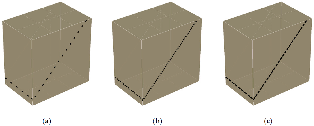
In this section, the results of boxes are presented for both physical tests and numerical simulations. The boxes selected in the study represent a common flap box design of FEFCO 201, although with perforations included on the front and sidewalls. One box design was considered with dimensions of 300 × 200 × 300 mm. All boxes considered here had the same overall design. However, it was considered with three types of different perforations of the SRP type, see Figure 3 (cf. see Figure 1b). The perforations were on three walls, in which, on two opposite walls they were diagonally inclined (30 mm from both corners), and on one wall, in-between wall, the perforation was horizontally positioned (30 mm from the bottom).
In the study, the perforations were described by two values, namely, A × B, where A means the percentage of the length of 10 mm, in which the knife cut the corrugated cardboard, and B means the percentage of the length of 10 mm, in which the corrugated cardboard was intact. Thus, the following perforations were considered in the study: 25 × 75, 50 × 50 and 75 × 25 (in decreasing order of perforation/box strength).
The boxes selected in the study were subjected to compression in a strength testing machine, namely BCT-19T10 from FEM at [37]; see Figure 1c. According to the specification, the testing machine has a 0.1 N resolution of force control and may induce the force up to 10 kN. The displacement may be controlled with 0.001 mm accuracy. For each type of perforation, five box samples were tested to acquire a representative result. For 50 × 50 perforation, one of the test results was rejected due to unusual deformation mode. Thus, finally, 14 measurements of ultimate loads of boxes with perforations were used in the study, see Table 1. In Table 1, the mean values computed with two standard deviations, which, for the normal distribution, accounts for 95.5% of cases for each box design, are also presented.
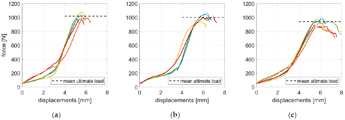
The samples were produced from the same corrugated cardboard, namely single-side three-layer quality with E flute of 450 g/m2 (marked as 3E450-1). Cardboard thickness measured was from 1.58 mm to 1.60 mm, with the mean equal to 1.59 mm. Each box sample was cut by plotter and manually folded; at the top and bottom, the flaps were taped. Since the plotter was used, no converted corrugated cardboard, i.e., raw cardboard material without printing, lamination, etc., was taken into consideration in this study. Before and after the test, the cardboard/box samples were visually inspected for any damages or unusual issues. Boxes were subjected to a displacement control test. The resultant force was registered by the testing machine (no additional strain gauges were used). Cardboard was laboratory conditioned with a temperature of 23°C ± 1°C and relative humidity of 50% ± 2%, TAPPI standard T402 was used. In Figure 4, the full histories of the box measurements are presented. The histories represent the force versus displacement data obtained from the strength testing machine [37]. Note that good repeatability of the histories of the measurements was observed.
The experimental results, namely, the mean ultimate loads computed from the peak forces (presented in Figure 4 and Table 1), were used to verify the approach proposed in the paper, see Equation (23). According to the proposed method, the critical buckling loads from the first buckling mode of all box panels (computed separately; with and without perforations) were computed via the FE model to use them in Equation (23). In Supplementary Materials, the data were attached, which feed the Equation (23), and served to compute the estimations of the ultimate loads of boxes with perforations. In Table 2, the material constants were demonstrated, which were the input for the constitutive law used in the FEM computations. Apart from the mean values, in order to show the uncertainty of the data, the minimum and maximum values were also presented. Moderate scatter of the material constants was observed.
The data used in Table 2 and the selected equations presented earlier may be used to determine the typical set of elastic orthotropic material constants. One of the issue to address is to compute , which, according to Equation (19), depends on the Poisson’s ratios, and . Here, the Baum et al. [45] formula was used to compute , namely:
In the above equation, the relation was obtained from Equation (11); thus, we may write the following formula:
On the other hand, the ratio was computed from the classic formula, namely:
In the above equation, the following relation, derived again from Equation (11), may be used:
Finally, having , allows us to compute and from the Equation (11). Similarly, was computed from Equation (13); and were obtained from Equation (17) and Equation (18), respectively. The computed material constants are presented in Table 3; mean, minimal, and maximal values are demonstrated.
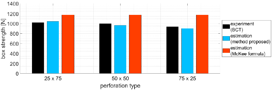
In Figure 5, the mean data from the physical measurements, and estimated counterpart values were presented by the bar plot. Black bars represent the mean values measured at the laboratory, see the last column in Table 1. The values obtained from the analytical–numerical approach proposed are presented by light blue plot, see Equation (23). In the analytical–numerical approach presented, and used were and .
The comparison between the measured and estimated values of ultimate loads of the boxes with perforations may be represented by the mean error. It was computed for all three cases according to the following formula:
where is an experimental value of the box compression strength averaged for four or five samples with peculiar perforation, and is its counterpart computed by the analytical–numerical approach proposed in this paper. The average error, while using the analytical–numerical approach for the boxes analyzed in this paper was 3.5%.
A similar comparison with the experimental values may be considered for the estimation via McKee formula—the approach, which is easy, and thus in common use in the packaging industry. The results were presented by red bars in Figure 5, see Equation (30). Similarly, the mean error for the McKee formula was computed, it was equal to 19.5%. The summary of the mean errors is presented in Table 4.
4. Discussion
The analytical–numerical method proposed here shows the correct trend while comparing it with the experimental results. Namely, with decreasing stiffness of the perforation, the strength of the box also decreases. Experimental results show that, if the box with 50 × 50 perforation would be the reference, the strength increase for 25 × 75 is 2.0%, while for 75 × 25 the decrease equals 6.3%. For the analytical–numerical approach proposed, the counterpart values are 8.4% and 6.5%, respectively. For the McKee formula, the values are constant for all three boxes. Moreover, note that the average error computed for the method proposed here was more than five times smaller than for the McKee formula, i.e., 3.5% vs. 19.5%, respectively. This is the most important conclusion from our study. The proposed approach is much more accurate than a simplified method.
In the study presented, all designs of the boxes, due to the same overall geometry, had 1000 mm of the in-plane circumference. This caused the strength of the boxes to be the same for all three box designs with perforations, while considering the McKee formula approach, see Figure 5. The McKee formula does not include the information about perforations in the box design.
Many challenges are still actual in the mechanics of corrugated cardboards and packaging due to the nonlinear material and the nonlinear/discontinuous geometry of the designs. Previously, the box strength was computed with the simplified formulas, which currently does not provide sufficient accuracy to the increasing needs of the packaging industry. This was proved by our recent series of publications, namely in [11,12,20,21].
5. Conclusions
In this study, the boxes made of corrugated cardboards with knife-cut perforations were analyzed. The box designs selected for the study represented the SRPs. Three types of perforations were considered, namely, 25 × 75, 50 × 50, and 75 × 25, in which the first value represents the percentage of the length of 10 mm, at which the knife cut the corrugated cardboard, and the second value represents the percentage of the length of 10 mm, at which the corrugated cardboard was intact.
In the first part of the study, the series of top-to-bottom compression strength tests of boxes were conducted to determine their experimental ultimate loads. In the second part of the study, the analytical–numerical approach was proposed to take into consideration the different properties of perforations in modeling. In the third part of the study, the boxes with their peculiar design of perforations were modeled with simplified (McKee formula) and proposed the analytical–numerical approach. The tests conducted in the first part served to verify the modeling approach proposed in the second part of the study. In the third part of the study, it appeared that the approach proposed in the paper gave very low mean estimation error in comparison with the reference simplified (McKee formula) approach; the mean error was only a few percent. The McKee formula approach was presented to contrast the influence of the perforation on the estimation of the box ultimate load, according to the classical approach still widely used by the lab technicians. Thus, it can be concluded that the method presented in the study is a promising tool for determining the strength of perforated boxes, which are commonly used in the supply and sales market. To the best knowledge of the authors, the influence of the perforations has never been considered before in the analytical or analytical–numerical approach for estimation of the compressive strength of boxes made of corrugated cardboard. The novelty of the presented work is the use of the analytical–numerical method, which finally takes into account the impact of perforation on the evaluation of the compressive strength of the SRP packaging.
Supplementary Materials
The following are available online at https://0-www-mdpi-com.brum.beds.ac.uk/1996-1073/14/4/1095/s1. In the TXT file, the computational results based on the method proposed, in which Figure 5 was generated are presented. In this file, the 1st and 2nd columns are and parameters; the 3rd column is the ECT value for particular cardboard quality; the 4th to 7th columns are critical loads of the -th panel (obtained from FEM); the 8th to 11th columns are the reduction factors due to the in-plate aspect ratio of the box panel, , where and denotes the number of the panel. The 12th to 15th columns are the reduction factors, taking into account the ratio of the compressive strength of the plate with and without a perforation , where and denotes the number of the panel. The 16th to 19th columns are the widths of the -th panel of the box.
Author Contributions
T.G. (Tomasz Garbowski): conceptualization, methodology, software, writing—original draft, writing—review and editing, supervision, project administration, funding acquisition; T.G. (Tomasz Gajewski): software, validation, formal analysis, investigation, writing—original draft, writing—review and editing, visualization; J.K.G.: writing—original draft, writing—review and editing, data curation, supervision, funding acquisition. All authors have read and agreed to the published version of the manuscript.
Funding
The APC was funded by the Ministry of Science and Higher Education, Poland, grant from Poznan University of Technology; grant number 0612/SBAD/3567.
Institutional Review Board Statement
Not applicable.
Informed Consent Statement
Not applicable.
Acknowledgments
Special thanks to the FEMAT company (www.fematsystems.pl) for the financial support of this research project. The authors also thank AQUILA VPK Września for providing samples of corrugated cardboard for the study.
Conflicts of Interest
The authors declare no conflict of interest.
References
- Leminena, V.; Tanninena, P.; Pesonena, A.; Varis, J. Effect of mechanical perforation on the press-forming process of paperboard. Procedia Manuf. 2019, 38, 1402–1408. [Google Scholar] [CrossRef]
- Sohrabpour, V.; Hellström, D. Models and software for corrugated board and box design. In Proceedings of the 18th International Conference on Engineering Design (ICED 11), Copenhagen, Denmark, 15–18 October 2011. [Google Scholar]
- McKee, R.C.; Gander, J.W.; Wachuta, J.R. Compression strength formula for corrugated boxes. Paperboard Packag. 1963, 48, 149–159. [Google Scholar]
- Kellicutt, K.; Landt, E. Development of design data for corrugated fiberboard shipping containers. Tappi J. 1952, 35, 398–402. [Google Scholar]
- Maltenfort, G. Compression strength of corrugated containers. Fibre Contain. 1956, 41, 106–121. [Google Scholar]
- Allerby, I.M.; Laing, G.N.; Cardwell, R.D. Compressive strength—From components to corrugated containers. Appita Conf. Notes 1985, 1–11. [Google Scholar]
- Schrampfer, K.E.; Whitsitt, W.J.; Baum, G.A. Combined Board Edge Crush (ECT) Technology; Institute of Paper Chemistry: Appleton, WI, USA, 1987. [Google Scholar]
- Batelka, J.J.; Smith, C.N. Package Compression Model; Institute of Paper Science and Technology: Atlanta, GA, USA, 1993. [Google Scholar]
- Urbanik, T.J.; Frank, B. Box compression analysis of world-wide data spanning 46 years. Wood Fiber Sci. 2006, 38, 399–416. [Google Scholar]
- Avilés, F.; Carlsson, L.A.; May-Pat, A. A shear-corrected formulation of the sandwich twist specimen. Exp. Mech. 2012, 52, 17–23. [Google Scholar] [CrossRef]
- Garbowski, T.; Gajewski, T.; Grabski, J.K. The role of buckling in the estimation of compressive strength of corrugated cardboard boxes. Materials 2020, 13, 4578. [Google Scholar] [CrossRef] [PubMed]
- Garbowski, T.; Gajewski, T.; Grabski, J.K. Estimation of the compressive strength of corrugated cardboard boxes with various openings. Energies 2021, 14, 155. [Google Scholar] [CrossRef]
- Frank, B. Corrugated box compression—A literature survey. Packag. Technol. Sci. 2014, 27, 105–128. [Google Scholar] [CrossRef]
- Stott, R.A. Compression and stacking strength of corrugated fibreboard containers. Appita J. 2017, 70, 76–82. [Google Scholar]
- Junli, W.; Quancheng, Z. Effect of moisture content of corrugated box on mechanical properties. J. Lanzhou Jiaotong Univ. 2006, 25, 134–136. [Google Scholar]
- Archaviboonyobul, T.; Chaveesuk, R.; Singh, J.; Jinkarn, T. An analysis of the influence of hand hole and ventilation hole design on compressive strength of corrugated fiberboard boxes by an artificial neural network model. Packag. Technol. Sci. 2020, 33, 171–181. [Google Scholar] [CrossRef]
- Zhang, Y.-L.; Chen, J.; Wu, Y.; Sun, J. Analysis of hazard factors of the use of corrugated carton in packaging low-temperature yogurt during logistics. Procedia Environ. Sci. 2011, 10, 968–973. [Google Scholar] [CrossRef] [Green Version]
- Nordstrand, T. Basic Testing and Strength Design of Corrugated Board and Containers. Ph.D. Thesis, Lund University, Lund, Sweden, 2003. [Google Scholar]
- Nordstrand, T.; Carlsson, L. Evaluation of transverse shear stiffness of structural core sandwich plates. Comp. Struct. 1997, 37, 145–153. [Google Scholar] [CrossRef]
- Garbowski, T.; Gajewski, T.; Grabski, J.K. Role of transverse shear modulus in the performance of corrugated materials. Materials 2020, 13, 3791. [Google Scholar] [CrossRef] [PubMed]
- Garbowski, T.; Gajewski, T.; Grabski, J.K. Torsional and transversal stiffness of orthotropic sandwich panels. Materials 2020, 13, 5016. [Google Scholar] [CrossRef]
- Urbanik, T.J.; Saliklis, E.P. Finite element corroboration of buckling phenomena observed in corrugated boxes. Wood Fiber Sci. 2003, 35, 322–333. [Google Scholar]
- Garbowski, T.; Jarmuszczak, M. Homogenization of corrugated paperboard. Part 1. Analytical homogenization. Pol. Pap. Rev. 2014, 70, 345–349. (In Polish) [Google Scholar]
- Garbowski, T.; Jarmuszczak, M. Homogenization of corrugated paperboard. Part 2. Numerical homogenization. Pol. Pap. Rev. 2014, 70, 390–394. (In Polish) [Google Scholar]
- Marek, A.; Garbowski, T. Homogenization of sandwich panels. Comput. Assist. Methods Eng. Sci. 2015, 22, 39–50. [Google Scholar]
- Garbowski, T.; Marek, A. Homogenization of corrugated boards through inverse analysis. In Proceedings of the 1st International Conference on Engineering and Applied Sciences Optimization, Kos Island, Greece, 4–6 June 2014; pp. 1751–1766. [Google Scholar]
- Hohe, J. A direct homogenization approach for determination of the stiffness matrix for microheterogeneous plates with application to sandwich panels. Compos. Part B 2003, 34, 615–626. [Google Scholar] [CrossRef]
- Buannic, N.; Cartraud, P.; Quesnel, T. Homogenization of corrugated core sandwich panels. Comp. Struct. 2003, 59, 299–312. [Google Scholar] [CrossRef] [Green Version]
- Biancolini, M.E. Evaluation of equivalent stiffness properties of corrugated board. Comp. Struct. 2005, 69, 322–328. [Google Scholar] [CrossRef]
- Abbès, B.; Guo, Y.Q. Analytic homogenization for torsion of orthotropic sandwich plates: Application. Comp. Struct. 2010, 92, 699–706. [Google Scholar] [CrossRef]
- Thakkar, B.K.; Gooren, L.G.J.; Peerlings, R.H.J.; Geers, M.G.D. Experimental and numerical investigation of creasing in corrugated paperboard. Philos. Mag. 2008, 88, 3299–3310. [Google Scholar] [CrossRef] [Green Version]
- Beex, L.A.A.; Peerlings, R.H.J. An experimental and computational study of laminated paperboard creasing and folding. Int. J. Solids Struct. 2009, 46, 4192–4207. [Google Scholar] [CrossRef] [Green Version]
- Giampieri, A.; Perego, U.; Borsari, R. A constitutive model for the mechanical response of the folding of creased paperboard. Int. J. Solids Struct. 2011, 48, 2275–2287. [Google Scholar] [CrossRef] [Green Version]
- Domaneschi, M.; Perego, U.; Borgqvist, E.; Borsari, R. An industry-oriented strategy for the finite element simulation of paperboard creasing and folding. Pack. Technol. Sci. 2017, 30, 269–294. [Google Scholar] [CrossRef]
- Awais, M.; Tanninen, P.; Leppänen, T.; Matthews, S.; Sorvari, J.; Varis, J.; Backfol, K. A computational and experimental analysis of crease behavior in press forming process. Procedia Manuf. 2018, 17, 835–842. [Google Scholar] [CrossRef]
- Heimerl, G.J. Determination of plate compressive strengths. In National Advisory Committee for Aeronautics; Technical Note number 1480; National Advisory Committee for Aeronautics (NACA): Washington, DC, USA, 1947. [Google Scholar]
- FEMat Systems. Available online: http://www.fematsystems.pl/en/systems/bct/ (accessed on 26 March 2020).
- Ventsel, E.; Krauthammer, T. Thin Plates and Shells. Theory, Analysis, and Applications; Marcel Dekker, Inc.: New York, NY, USA, 2001. [Google Scholar]
- Norstrand, T. On buckling loads for edge-loaded orthotropic plates including transverse shear. Comp. Struct. 2004, 65, 1–6. [Google Scholar] [CrossRef]
- Wang, C.M.; Wang, C.Y.; Reddy, J.N. Exact Solutions for Buckling of Structural Members; CRC Press: Boca Raton, FL, USA, 2005. [Google Scholar]
- Zienkiewicz, O.C.; Taylor, R.L.; Papadopoulus, P.; Onate, E. Plate bending elements with discrete constraints: New Triangular Elements. Comput. Struct. 1990, 35, 505–522. [Google Scholar] [CrossRef]
- Zienkiewicz, O.C.; Taylor, R.L. The Finite Element Method for Solid and Structural Mechanics, 6th ed.; Butterworth-Heinemann: Oxford, UK, 2005. [Google Scholar]
- Onate, E.; Castro, J. Derivation of Plate Elements Based on Assumed Shear Strain Fields. In Recent Advances on Computational Structural Mechanics; Ladeveze, P., Zienkiewicz, O.C., Eds.; Elsevier Pub: Amsterdam, The Netherlands, 1991. [Google Scholar]
- Garbowski, T.; Borysiewicz, A. The stability of corrugated board packages. Pol. Pap. Rev. 2014, 70, 452–458. (In Polish) [Google Scholar]
- Baum, G.A.; Habeger, C.; Fleischman, H. Measurement of the orthotropic elastic constants of paper. IPC Tech. Pap. Ser. 1981, 117. [Google Scholar]
Figure 1.
(a) A panel b × a separated from corrugated box as a pined plate under in-plane compression; (b) corrugated board packaging with perforations; (c) box compression test (BCT) press used in laboratory tests [37].
Figure 1.
(a) A panel b × a separated from corrugated box as a pined plate under in-plane compression; (b) corrugated board packaging with perforations; (c) box compression test (BCT) press used in laboratory tests [37].

Figure 2.
(a) Triangular mesh on a single panel with perforation; (b) spring connection between two parts separated by a perforation; (c) thickness reduction of elements adjacent to perforation.
Figure 2.
(a) Triangular mesh on a single panel with perforation; (b) spring connection between two parts separated by a perforation; (c) thickness reduction of elements adjacent to perforation.

Figure 3.
Schematic designs of FEFCO 201 box with different perforations considered in the study: (a) 25 × 75, (b) 50 × 50 and (c) 75 × 25.
Figure 3.
Schematic designs of FEFCO 201 box with different perforations considered in the study: (a) 25 × 75, (b) 50 × 50 and (c) 75 × 25.

Figure 4.
Measurements from a box compression test machine [37] for FEFCO 201 box with different perforations: (a) 25 × 75, (b) 50 × 50 and (c) 75 × 25.
Figure 4.
Measurements from a box compression test machine [37] for FEFCO 201 box with different perforations: (a) 25 × 75, (b) 50 × 50 and (c) 75 × 25.

Figure 5.
Box compression strength obtained within different approach for shelf-ready boxes considered in the study with various perforations, i.e., 25 × 75, 50 × 50 and 75 × 25.
Figure 5.
Box compression strength obtained within different approach for shelf-ready boxes considered in the study with various perforations, i.e., 25 × 75, 50 × 50 and 75 × 25.


Table 1.
Experimental ultimate loads of boxes tested in the study with different perforation types.
| No. | Type of Perforation | Ultimate Load (N) | Mean Ultimate Load ± 2 Standard Deviations (N) |
|---|---|---|---|
| 1 | 25 × 75 | 1033.0 | 1020 ± 77.8 |
| 2 | 1078.0 | ||
| 3 | 1003.0 | ||
| 4 | 974.7 | ||
| 5 | 1009.0 | ||
| 6 | 50 × 50 | 1050.0 | 1002.0 ± 98.4 |
| 7 | 933.6 | ||
| 8 | 1017.3 | ||
| 9 | 1007.0 | ||
| 10 | 75 × 25 | 987.8 | 939.3 ± 95.6 |
| 11 | 979.6 | ||
| 12 | 944.9 | ||
| 13 | 899.1 | ||
| 14 | 880.2 |
Table 2.
Material characteristics for 3E450-1 cardboard quality, which were used in the finite element method (FEM) to determine the critical buckling loads of the panels [44].
Table 2.
Material characteristics for 3E450-1 cardboard quality, which were used in the finite element method (FEM) to determine the critical buckling loads of the panels [44].
| 3E450-1 | Thickness (mm) | ECT | (Nmm) | (Nmm) | (Nmm) | (N/mm) | (N/mm) |
|---|---|---|---|---|---|---|---|
| mean | 1.589 | 5.299 | 1261 | 507.8 | 1036 | 3.904 | 4.074 |
| min | 1.582 | 5.028 | 1206 | 469.2 | 967 | 3.743 | 3.691 |
| max | 1.596 | 5.574 | 1318 | 547.3 | 1115 | 4.077 | 4.498 |
Table 3.
Elastic orthotropic parameters for 3E450-1 cardboard quality computed from stiffnesses, see Table 2.
Table 3.
Elastic orthotropic parameters for 3E450-1 cardboard quality computed from stiffnesses, see Table 2.
| 3E450-1 | |||||||
|---|---|---|---|---|---|---|---|
| mean | 3451 | 1390 | 0.461 | 0.184 | 3099 | 2.95 | 3.08 |
| min | 3340 | 1301 | 0.450 | 0.183 | 2931 | 2.84 | 2.80 |
| max | 3560 | 1478 | 0.470 | 0.189 | 3291 | 3.07 | 3.38 |
Table 4.
The mean error for estimations of McKee formula and the method proposed.
| Case | (-) | (-) | Mean Error (%) |
|---|---|---|---|
| McKee formula | 0.4215 | 0.746 | 19.5 |
| method proposed | 0.4 | 0.75 | 3.5 |
Publisher’s Note: MDPI stays neutral with regard to jurisdictional claims in published maps and institutional affiliations. |
© 2021 by the authors. Licensee MDPI, Basel, Switzerland. This article is an open access article distributed under the terms and conditions of the Creative Commons Attribution (CC BY) license (http://creativecommons.org/licenses/by/4.0/).
Share and Cite
MDPI and ACS Style
Garbowski, T.; Gajewski, T.; Grabski, J.K. Estimation of the Compressive Strength of Corrugated Cardboard Boxes with Various Perforations. Energies 2021, 14, 1095. https://0-doi-org.brum.beds.ac.uk/10.3390/en14041095
AMA Style
Garbowski T, Gajewski T, Grabski JK. Estimation of the Compressive Strength of Corrugated Cardboard Boxes with Various Perforations. Energies. 2021; 14(4):1095. https://0-doi-org.brum.beds.ac.uk/10.3390/en14041095
Chicago/Turabian StyleGarbowski, Tomasz, Tomasz Gajewski, and Jakub Krzysztof Grabski. 2021. "Estimation of the Compressive Strength of Corrugated Cardboard Boxes with Various Perforations" Energies 14, no. 4: 1095. https://0-doi-org.brum.beds.ac.uk/10.3390/en14041095
Note that from the first issue of 2016, this journal uses article numbers instead of page numbers. See further details here.