
Modified SPWM Technique with Zero-Sequence Voltage Injection for a Five-Phase, Three-Level NPC Inverter


1
Faculty of Electrical Engineering, University of Nigeria, 410001 Nsukka, Nigeria
2
Faculty of Electrical and Control Engineering, Gdańsk University of Technology, 80-233 Gdańsk, Poland
3
Faculty of Electrical Engineering, Czestochowa University of Technology, 42-201 Częstochowa, Poland
*
Author to whom correspondence should be addressed.
†
These authors contributed equally to this work.
Energies 2021, 14(4), 1198; https://0-doi-org.brum.beds.ac.uk/10.3390/en14041198
Submission received: 6 February 2021
/
Revised: 12 February 2021
/
Accepted: 20 February 2021
/
Published: 23 February 2021
(This article belongs to the Special Issue Control and Modeling of Power Converters and Inverters)
Abstract
:This article presents a modified sinusoidal pulse-width modulation (SPWM) scheme for a five-phase, three-level neutral-point-clamped inverter. The modulation scheme deploys a modified min–max function to inject the zero-sequence components into the reference modulating signals; hence enabling the effective utilization of the DC-link voltage. Balanced split-input DC-link voltages were achieved through further incorporation of adjustable voltage-dependent variables into the reference signals. The dynamic performance of the control approach is demonstrated through simulations and experiments on a laboratory inverter prototype; the results are well presented.
1. Introduction
In recent times, the global search for environmental friendly energy sources has demanded the use of appropriate harvesting devices to fully tap these renewable energy sources. In addition, there is unceasing demand for high power density and reliability in various industrial drive systems. These demands can be met with the concepts of multilevel converters for power electronics and multiphase systems in electric power systems.
Multiphase power inverters are becoming increasingly popular in the drive systems of power electronics. Traditional two-level and multilevel inverter configurations have been explored for this very purpose. Multiphase motor drive systems offer a series of advantages over corresponding three-phase motor drive systems: lower torque ripple magnitude, higher frequency of torque ripple, higher torque density due to the injection of lower-order harmonics that modify the shape of the air-gap flux, lower per-leg converter rating for the same power output, higher redundancy and better fault tolerance characteristics, greater control flexibility, and the possibility of the independent control of more than one motor supplied by one power inverter [1,2].
The independent generation of output voltage components (fundamental and third harmonic frequencies) can improve the nominal torque of five-phase motors with a quasi-rectangular air-gap flux of up to 15%. The torque can be enhanced through the injection of the third harmonic into the motor current [3,4,5,6]. For a two-motor system supplied by one inverter, the first and third harmonic components of the inverter output voltage have to be generated and controlled independently. After phase transposition in series-connected motors, independent control of two induction motors with a sinusoidal field distribution can be achieved with these voltage harmonic components [7,8].
In the deployment of inverters in power-conditioning systems, certain specified measures and criteria are expected to be met by the inverters of power electronics, of which a range of operational output voltage, current, and power quality indices are crucial. The multilevel inverter (MLI) is, for now, the best device for the provision of these requirements. The classical MLI configurations include: cascaded H-bridge (CHB), diode-clamped, and capacitor-clamped (flying capacitor) MLIs. The ability to generate medium- and high-output voltages with low-voltage-rated devices, operation with low switching losses and audible noise, and generation of output voltages with low harmonic distortion are among the inherent advantages of MLI topologies. Except for the CHB MLI, the most commonly used and popular fundamental MLI configurations have been limited to the syntheses of three-level output voltages due to the innate operational imbalance in the constituting capacitor banks’ voltages and associated complex control [9,10]. These three-level inverter configurations have attained industrial maturity and have been made commercially available over recent years. The most often deployed traditional three-level inverter topology in low- and medium-voltage industrial drive applications and renewable energy harvesting is the three-level neutral-point-clamped (NPC) inverter [10,11,12]. The salient inherent topological features that necessitate its widespread acceptance and deployment are the use of a single DC source with splitting capacitor banks and half-DC-link-voltage-rated active power switches. The splitting of the input voltage source by the capacitor banks enables NPC inverters to synthesize a three-level output voltage waveform with reference to the common node of the capacitor banks (neutral-point). In operation, the variation in the neutral-point voltage is reflected in the splitting capacitor banks’ voltages and generates an imbalance between them. This voltage imbalance negatively affects the dynamic performance of the inverter. The problem with these negative effects is the development of undue voltage stresses on the constitutive power switches. Therefore, an appropriate voltage balancing control scheme is inevitable for the stable operation of an NPC inverter.
An appropriate modulation strategy is crucial in ameliorating the splitting capacitor voltage fluctuations in the three-level NPC inverter. Series of three-level modulation techniques have been well documented in the literature for multiphase NPC inverters. They can be broadly classified into two groups: space vector pulse width modulation (SVPWM) and sinusoidal pulse width modulation (SPWM) methods [11,12,13,14,15,16,17,18,19,20,21]. Clearly, the two pulse width modulation (PWM) approaches differ principally from each other in the way that the zero vector is applied. The zero vectors are symmetrically placed in a sample time in SVPWM. However, in SPWM, the modulating signals are symmetrically modified by injecting the zero-sequence using the nth harmonic and/or the min–max function. With these two approaches resolved, the two modulation schemes yield similar results. Based on its basic concepts, the extension of SVPWM from a three-phase system to a multiphase system usually involves rigorous and complex computational algorithms. A less-involved control approach presents itself in the SPWM scheme, which is sometimes referred to as carrier-based pulse width modulation (CBPWM). Unlike the SVPWM concepts, SPWM’s operational principle for generating gating signals is based on the inverter phase leg, that is, it is a phase modulation technique. This precisely implies that the same control concept is repeated in each phase of the inverter; the only control parameter difference is the phase angle shift. More precisely, the control concept involves the comparison of a high-frequency triangular carrier wave with fundamental-frequency sinusoidal modulating signals. In effect, SPWM presents no rigorous or complex computational difficulties, and its extension to multiphase systems involves only a multiplicity of the sinusoidal modulating signals.
In this work, the SPWM modulation approach is developed for firm control and utilization of the two DC-link capacitor voltages of a five-phase, three-level NPC inverter. The linear modulation range is increased by adding the zero-sequence voltage component, , to the sinusoidal voltage references using the min–max function. A simplified DC-link capacitor voltage balancing scheme is developed to instantaneously generate the needed balancing voltage pulses. These pulses are incorporated into the already synthesized min–max function. The inverter output voltage components (fundamental and third harmonic frequencies) are generated independently, and provide the possibility to control the series-connected motor independently. By following the proposed solution approach, the modulation algorithm can be easily extended to multiphase systems. The proposed SPWM strategy is validated with simulation and experimental results. In the following sections, the modulation scheme, DC-link capacitor voltage balancing, and simulation and experimental results are presented.
2. Proposed Control Scheme
2.1. Proposed SPWM Scheme
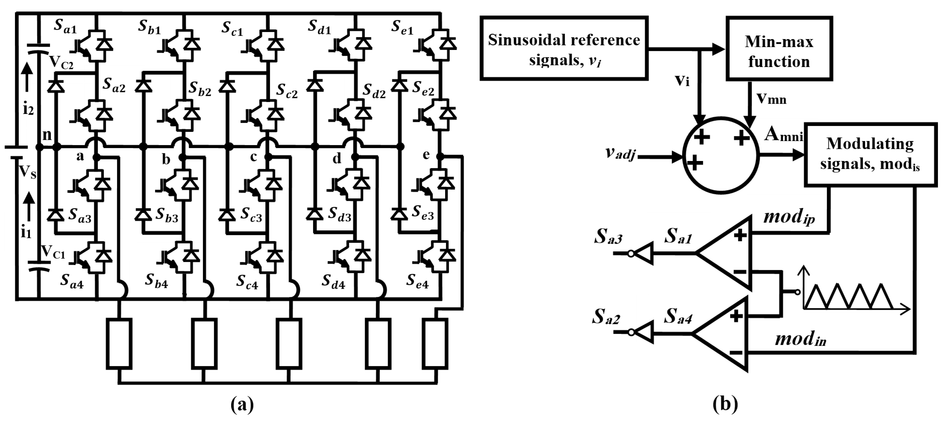
The power circuit and simplified control block diagram of the five-phase, three-level NPC inverter are shown in Figure 1. In Figure 1b, the index i is the phase-leg notation; , b, c, d, and e. The min–max function block generates the instantaneous minimum and maximum values of the five reference waveforms, as expressed in (1)–(3) [17].
The summer adds and a control signal, , to each phase-leg reference waveform, . The steps for generating will be explained in the next section. The modulating signal block receives the summer outputs, , and generates two signals per phase, and . These two signals are obtained using (5).
Finally, and are compared with a high-frequency triangular carrier to generate the four gating signals per phase. The peak values of this carrier signal are 0 and 1.
2.2. DC-Link Capacitor Voltage Balancing
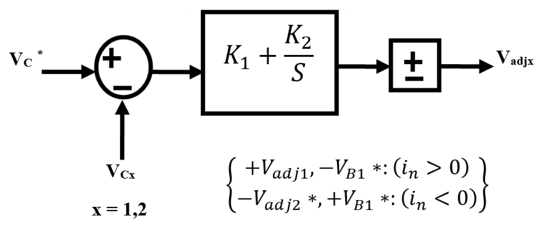
The use of the capacitor voltage balancing control is to make the individual capacitor voltages, and , follow a reference command, . Figure 2 shows the simple block diagram of the balancing control, where is the voltage command obtained from the balancing scheme. The capacitor voltage balancing is based on the flow of the neutral current, . Hence, the polarity of should be changed according to that of , whose expression is given in (6).
where and are the current flowing through the capacitors and , whose expressions are given in (7) and (8) [22,23].
The expressions for for x = 1, 2 are:
3. Simulation and Experimental Results
3.1. Simulation Results
The switching scheme depicted in Figure 1b was used to control the five-phase inverter. The carrier frequency is 3 kHz, and the DC input voltage magnitude, , is 1000 V. The capacitances of the DC-link capacitor banks, and , are both 1000 µF. Operational conditions depicting a wide range of load parameter variations are considered for load power factors of 0.6 and 0.8 at a modulation index of 0.95. The modulation index is defined as the ratio of the fundamental peak value of the phase voltage and one-half of the DC-link voltage. Using this definition, the phase and line voltages of the inverter can be expressed as functions of the modulation index. For a five-phase system, the maximum utilization of the DC-bus voltage (i.e., limit of the linear modulation region) is obtained when the peak value of the largest line voltage reaches the value of the DC-link voltage. Thus, the maximum value of the modulation index in a five-phase system is 10,515 [24]. These conditions will show the behavior/performance of the five-phase NPC inverter under the augmented zero-sequence voltage injection in SPWM. The proportional and integral constant coefficients, and , are obtained from earlier work on neutral-point current balancing [25,26]. Dynamic operations with and without the capacitor voltage balancing scheme will be demonstrated, as well as variation in the output load power factor.
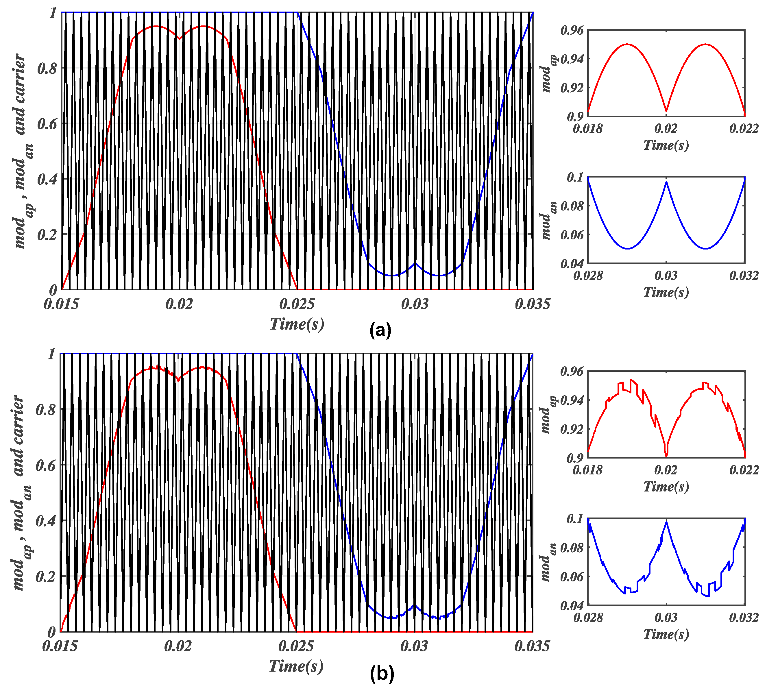
The first dynamic performance of the control scheme is under a constant power factor of 0.8, wherein the output load parameters are 20.94 Ω and 50 mH. The scheme in Figure 1b was implemented, and Figure 3a,b shows the simulated modulation signals with and without the voltage balancing scheme. In these figures, the peaks of the modulating signals have been zoomed (right side) to clearly show the effect of the zero-sequence addition to the pure reference sinusoids. In addition, the chopping effect of the proposed balancing scheme at these peaks is shown in Figure 3b (right-hand side).
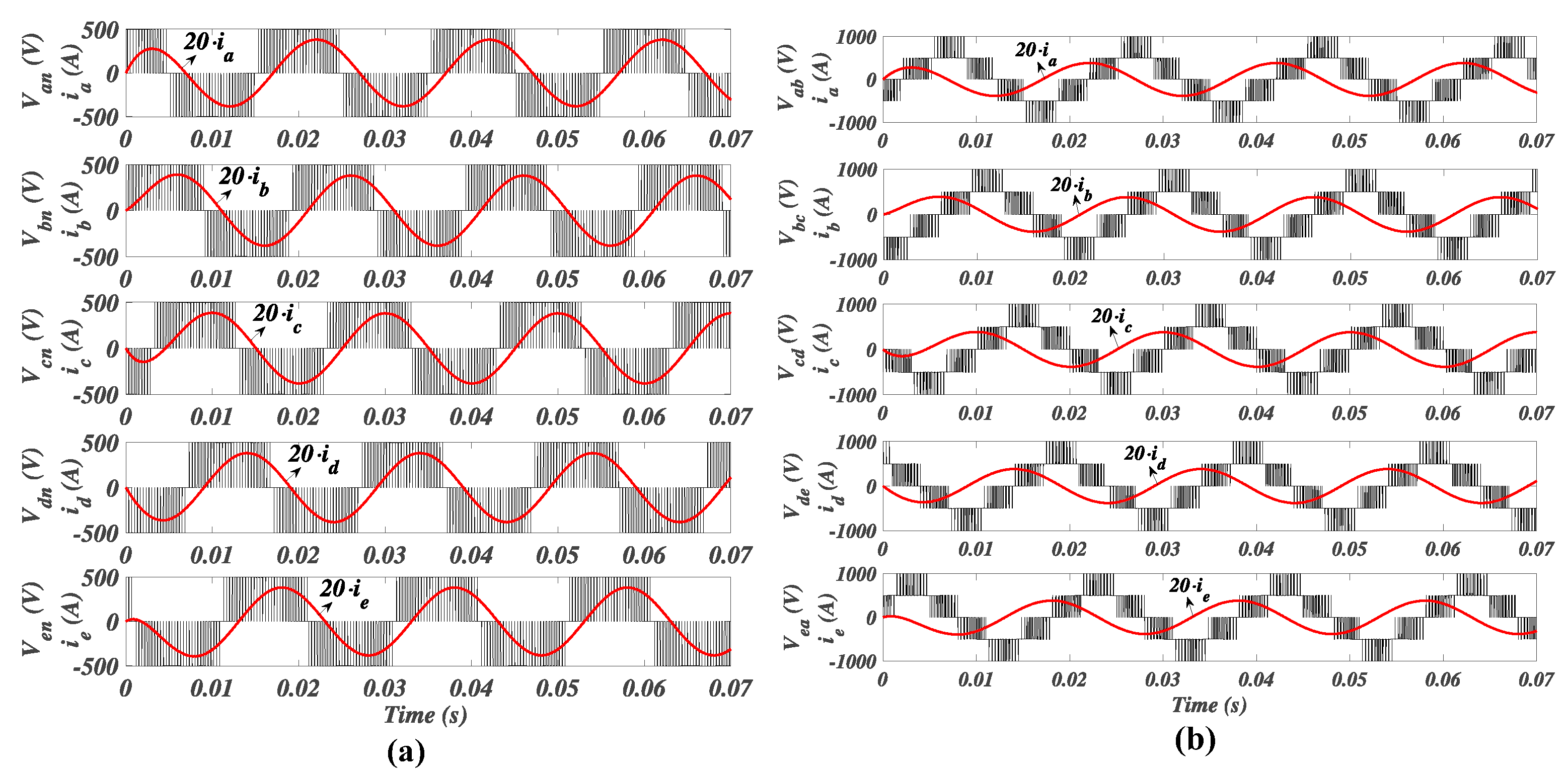
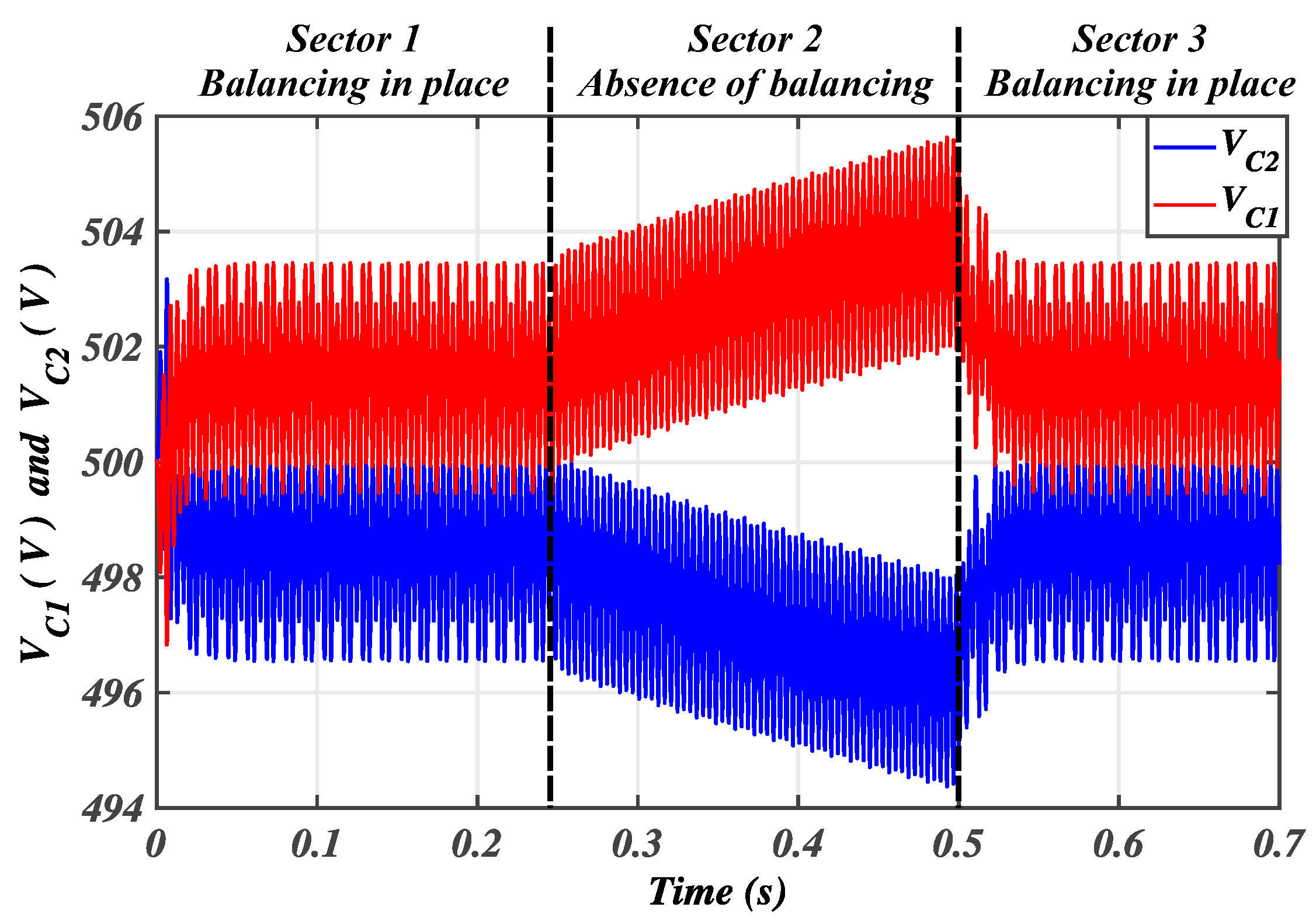
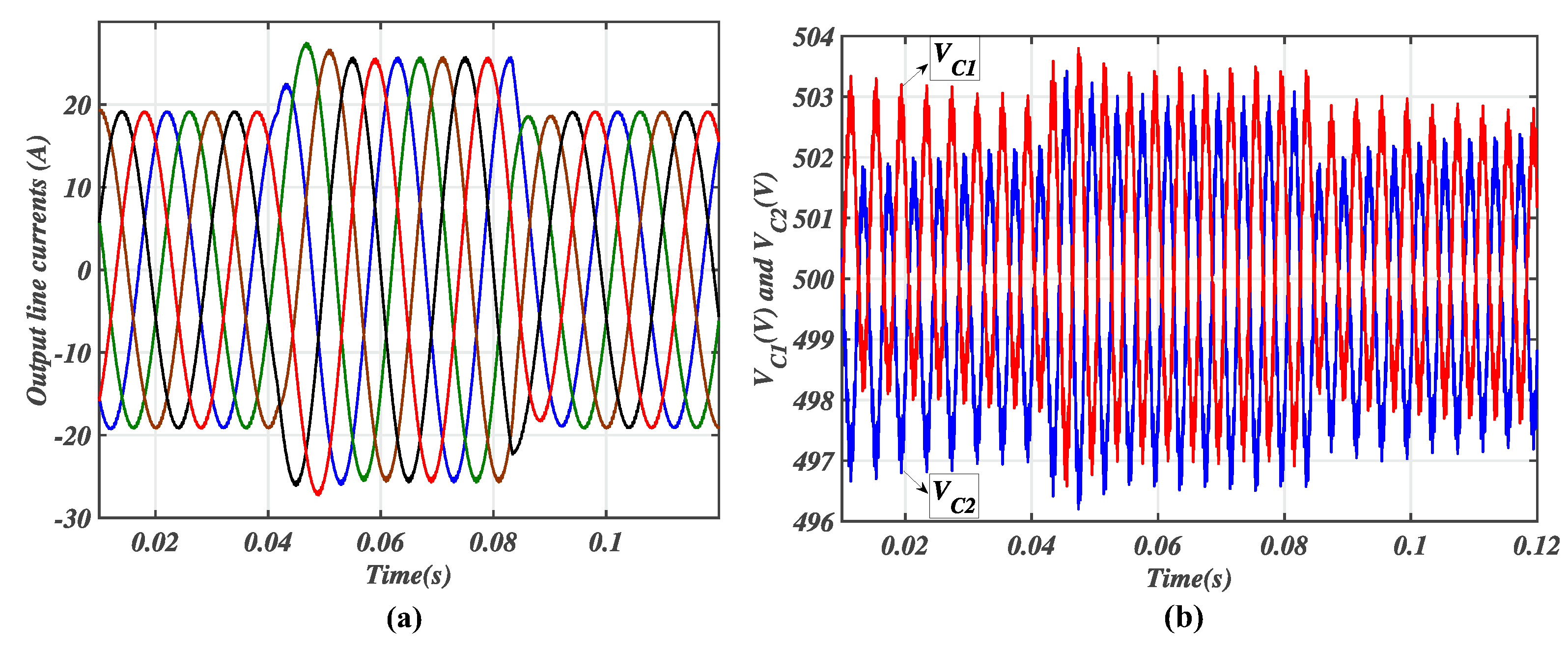
Figure 4 shows the simulated output voltage and current waveforms of the five-phase NPC inverter. As expected, these waveforms depict three and five levels, respectively. The two DC-link capacitor voltages’ profiles are displayed in Figure 5 in the presence and absence of the neutral voltage balancing scheme of Figure 2. In this figure, sector 2 actually depicts the need and essence of the proposed balancing scheme, since the splitting capacitor voltages were apparently derailed from the desired voltage value. Sectors 1 and 3 show the effectiveness of the presented balancing technique. The second dynamic performance of the control scheme is carried under varied output load parameters. The power factor is instantaneously changed from 0.8 to 0.6, and then back to to 0.8. Figure 6 shows the load currents’ variations as well as the dynamic response of the two DC-link capacitor voltages.
The power factor variations shown in Figure 6 are carried under varied output load values. The output RL load values are 20.94 Ω and 50 mH or 11.78 Ω and 50 mH when the power factors are 0.8 or 0.6, respectively. In Figure 6, the power factor was instantaneously changed from 0.8 to 0.6, and then back to 0.8.
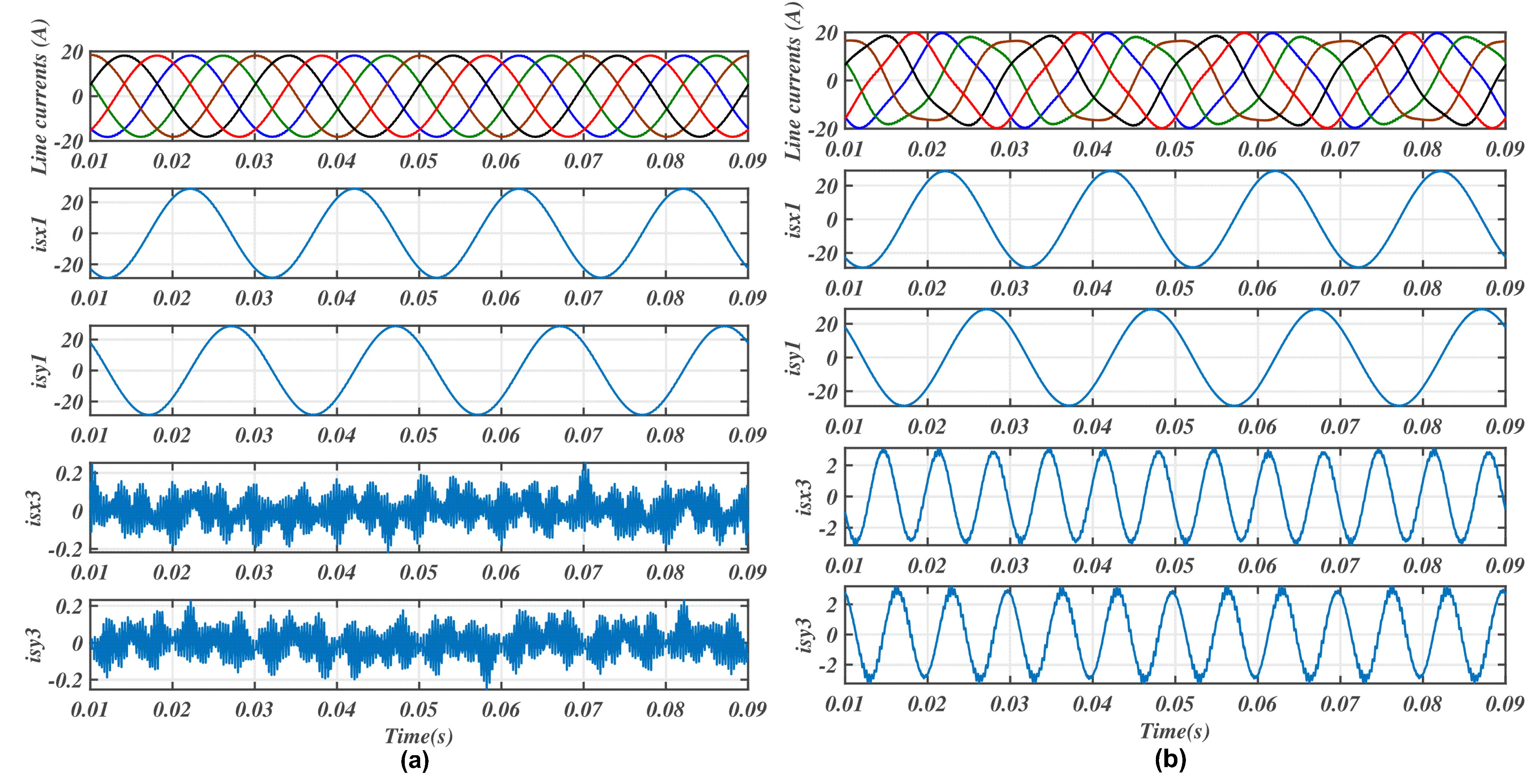
In Figure 7 the a, b, c, d, and e stator currents and their corresponding fundamental and third harmonic d-q components are shown. In Figure 7a, the modulation signals were processed with pure sinusoidal references. In effect, it can be seen that in this figure, the amplitude of the third harmonic components in the d-q axis is actually constituted of noise signals. However, in Figure 7b, the third harmonic component was injected into the modulation process, and consequently, the injected harmonic amplitude is seen in this figure with the commensurate amplitude in the d-q axis. This injected third harmonic amplitude is reflected in the distortion of the a, b, c, d, and e current waveforms, as evidenced in this figure. Such current shapes can be seen in earlier works on the effects of third harmonic components [3,6,27].
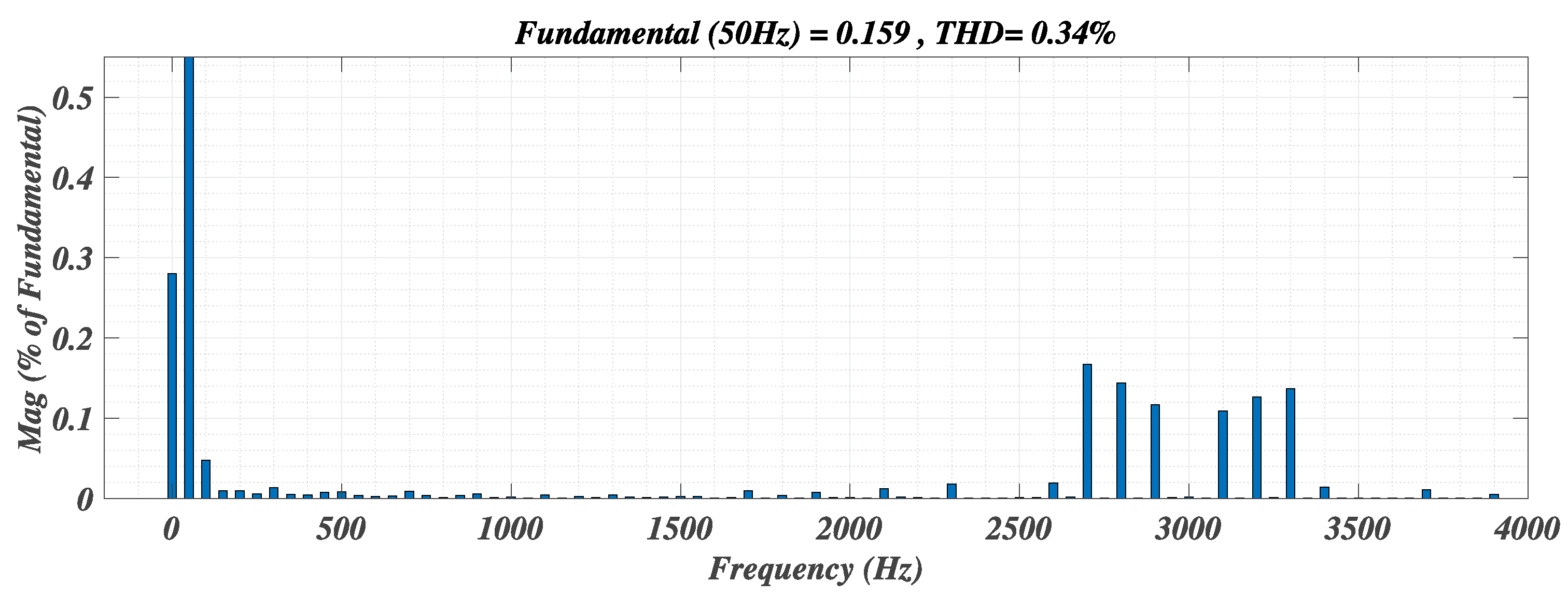
The FFT analysis of the output current waveform is displayed in Figure 8. The harmonic spectrum of the waveform shows the respective amplitudes of its constitutive harmonics. With the proposed balancing scheme, the current’s harmonic performance is satisfactory, as its THD value is equal to 0.34%.
3.2. Experimental Results
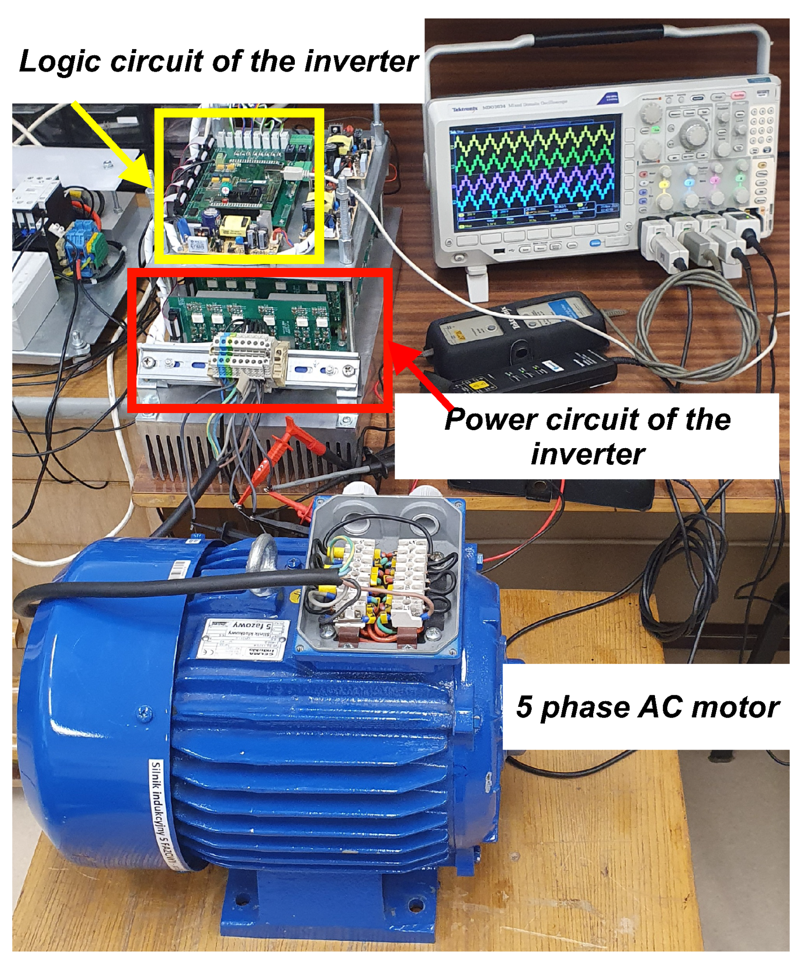
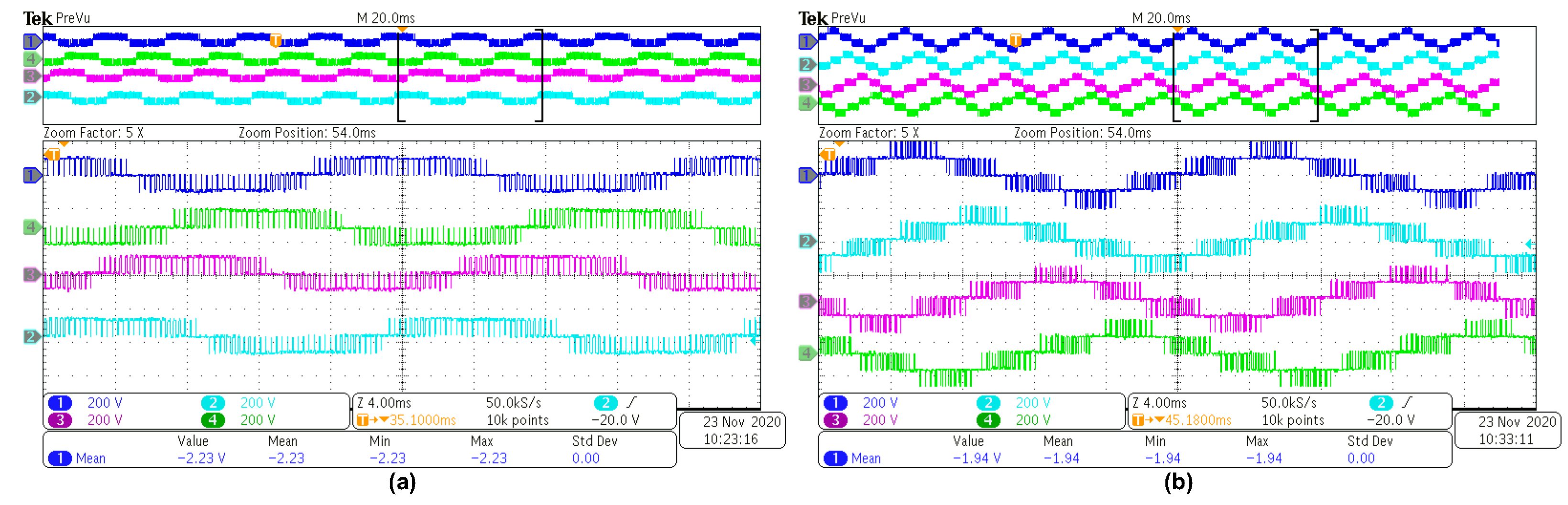
A scaled-down experimental prototype set-up of the five-phase, three-level neutral-point-clamped inverter with five-phase induction motor load is shown in Figure 9. An ADSP21363L DSP processor and Altera Cyclone II FPGA were used to generate the PWM signals. The modulation index was set to 0.95. The fundamental frequency was 50 Hz and the input DC-link voltage was approximately 200 V. Figure 10 shows the measured experimental waveforms of the inverter output voltages. In these waveforms, three- and five-level output voltages were generated for the neutral-point phase and line voltages, respectively. This is an agreement with the simulated output voltage waveforms in Figure 4.
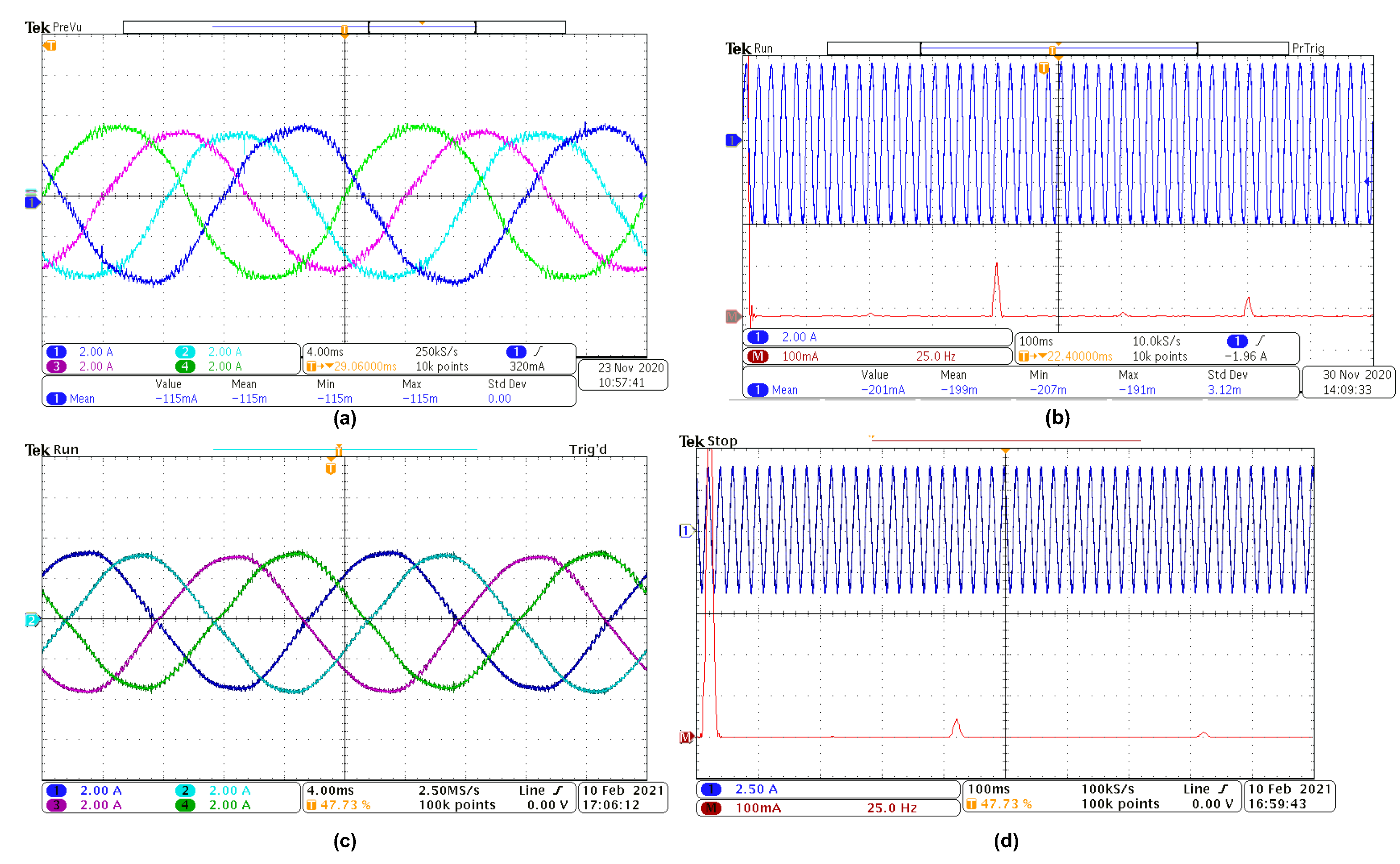
A zoomed sections of the waveforms are shown in Figure 11 to make the voltage amplitude recognition more clear. The difference between the output voltage amplitude values in the simulation (1000 V) and experiment (200 V) explains the flexibility and scalability of the modulation algorithm. The results obtained in the experiments with 200 V in the DC-link will have the same waveforms for 100 or 1000 V. The experimental output currents’ waveforms are shown in Figure 12 in the presence and absence of third harmonic injection. These waveforms have the same pattern as that obtained in the corresponding simulation. An FFT analysis of one phase of the inverter output current waveforms with third harmonic injection is displayed in Figure 12b. In this analysis, the harmonic spectrum of this current waveform is shown; therein, the first harmonic component at 50 Hz and the third harmonic component at the 150 kHz frequency are depicted. The amplitudes of the harmonics were: first harmonic component = 100% of the rated voltage, and third harmonic component = 10% of the rated voltage. Figure 12d shows the frequency spectrum of the inverter phase current without third harmonic injection.
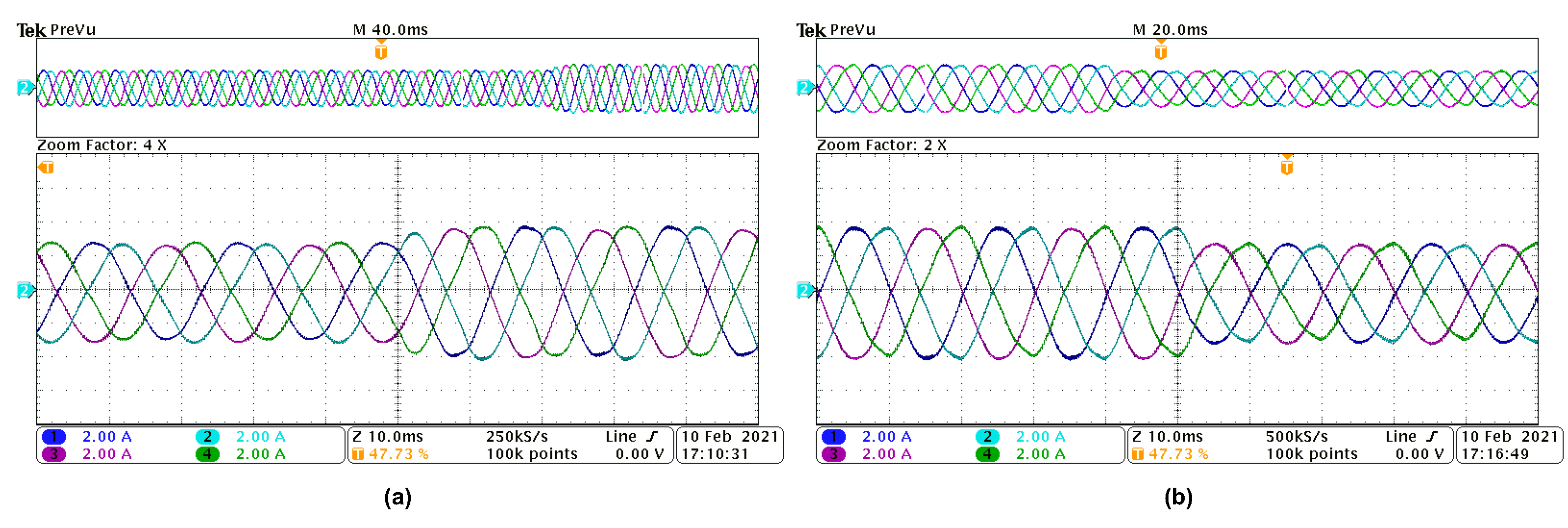
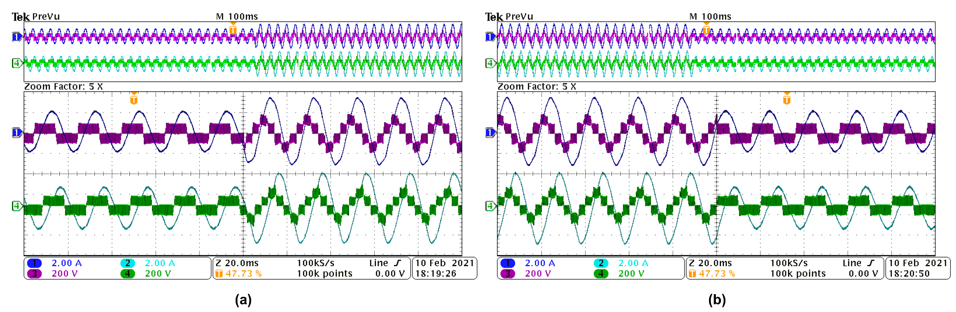
In addition, the dynamic responses of the inverter under the proposed control algorithm for step changes in the modulation index are shown in Figure 13 and Figure 14. In these figures, the modulation index value was changed from 0.6 to 1 and then back to 0.6. The corresponding dynamic variations of the inverter output line voltage waveform changed from three to five levels, and then from five to three levels, respectively. The dynamics of the line currents are seen in their amplitude variations; all current waveforms maintained their sinusoidal waveform.
The main goals of this experiment are to present the need for DC-link voltage balancing and to validate the appropriateness of the experimental and simulation results.
4. Conclusions
In this paper, an augmented zero-sequence voltage injection into SPWM for a five-phase, three-level neutral-point-clamped inverter was presented. The operational control concept, wherein modified sinusoidal modulating waveforms and their derived min–max functions are deployed in the generation of the switching pulses of the inverter, was explained in detail. A capacitor voltage control scheme that forces the splitting DC-link capacitor voltages to track a reference voltage command in dynamic operating conditions was developed. A wide range of load parameter variations (load power factors of 0.6 and 0.8) were used to show the performance of the five-phase NPC inverter under the augmented zero-sequence voltage injection in SPWM. Dynamic operations with and without the capacitor voltage balancing scheme were demonstrated. This presented control strategy can be extended to the control of any other NPC-driven electric machines. Simulated and experimental results were adequately presented for the five-phase NPC inverter.
Author Contributions
Conceptualization, A.L. and C.O.; methodology, C.O.; software, C.O. and D.K.; validation, C.O., D.K., and A.L.; formal analysis, C.O.; investigation, C.O. and D.K.; writing—original draft preparation, C.O. and D.K.; writing—review and editing, A.L. and A.J.; visualization, C.O. and D.K.; supervision, A.L.; project administration, A.L.; Funding acquisition A.J. All authors have read and agreed to the published version of the manuscript.
Funding
This research received no external funding.
Institutional Review Board Statement
Not applicable.
Informed Consent Statement
Not applicable.
Data Availability Statement
Not applicable.
Conflicts of Interest
The authors declare no conflict of interest.
References
- Levi, E. Advances in converter control and innovative exploitation of additional degrees of freedom for multiphase machines. IEEE Trans. Ind. Electron. 2016, 63, 433–448. [Google Scholar] [CrossRef] [Green Version]
- Duran, M.J.; Barrero, F. Recent advances in the design, modeling and control of multiphase machines—Part 2. IEEE Trans. Ind. Electron. 2016, 63, 459–468. [Google Scholar] [CrossRef]
- Levi, E.; Bojoi, R.; Profumo, F.; Toliyat, H.A.; Williamson, S. Multiphase IM drives—A technology status review. IET Elect. Power Appl. 2007, 1, 489–516. [Google Scholar] [CrossRef] [Green Version]
- Zarri, L.; Mengoni, M.; Tani, A.; Serra, G.; Casadei, D. Maximum-torque-per-ampere control of high torque-density multiphase drives based on induction motors. In Proceedings of the 2012 IEEE Energy Conversion Congress and Exposition (ECCE), Raleigh, NC, USA, 15–20 September 2012; pp. 495–502. [Google Scholar]
- Zimmermann, M.; Centner, M.; Stiebler, M. Five-phase permanent magnet synchronous machine under consideration of the third current harmonic. In Proceedings of the 2016 XXII International Conference on Electrical Machines (ICEM), Lausanne, Switzerland, 4–7 September 2016; pp. 2784–2788. [Google Scholar]
- Lewicki, A.; Strankowski, P.; Morawiec, M.; Guziński, J. Optimized space vector modulation strategy for five phase voltage source inverter with third harmonic injection. In Proceedings of the 2017 19th European Conference on Power Electronics and Applications (EPE’17 ECCE Europe), Warsaw, Poland, 11–14 September 2017; pp. 1–10. [Google Scholar]
- Levi, E.; Jones, M.; Vukosavic, S.N.; Iqbal, A.; Toliyat, H.A. Modeling Control and Experimental Investigation of a Five-phase Series-Connected Two-Motor Drive with Single Inverter Supply. IEEE Trans. Ind. Electron. 2007, 54, 1504–1516. [Google Scholar] [CrossRef]
- Chen, H.C.; Hsu, C.H.; Chang, D.K. Speed control for two series-connected five-phase permanent-magnet synchronous motors without position sensor. In Proceedings of the 2016 IEEE 25th International Symposium on Industrial Electronics (ISIE), Santa Clara, CA, USA, 8–10 June 2016; pp. 198–203. [Google Scholar]
- Zhang, Y.; Adam, G.P.; Lim, T.C.; Finney, S.J.; Williams, B.W. Voltage source converter In high voltage applications: Multilevel versus two-level converters. In Proceedings of the 9th IET International Conference on AC and DC Power Transmission (ACDC 2010), London, UK, 19–21 October 2010; Volume 57, pp. 1–5. [Google Scholar]
- Kouro, S.; Malinowski, M.; Gopakumar, K.; Pou, J.; Franquelo, L.G.; Wu, B.; Rodriguez, J.; Pérez, M.A.; Leon, J.I. Recent advances and industrial applications of multilevel converters. IEEE Trans. Ind. Electron. 2010, 57, 2553–2580. [Google Scholar] [CrossRef]
- Rodriguez, J.; Bernet, S.; Steimer, P.K.; Lizama, I.E. A survey on neutral-point-clamped inverters. IEEE Trans. Ind. Electron. 2010, 57, 2219–2230. [Google Scholar] [CrossRef]
- Franquelo, L.G.; Rodriguez, J.; Leon, J.I.; Kouro, S.; Portillo, R.; Prats, M. The age of multilevel converters arrives. IEEE Ind. Electron. Mag. 2008, 2, 28–39. [Google Scholar] [CrossRef] [Green Version]
- Engku Ariff, E.A.R.; Dordevic, O.; Jones, M. A space vector PWM technique for a three-level symmetrical six-phase drive. IEEE Trans. Ind. Electron. 2017, 64, 8396–8405. [Google Scholar] [CrossRef] [Green Version]
- Dordevic, O.; Levi, E.; Jones, M. A vector space decomposition based space vector PWM algorithm for a three-level seven-phase voltage source inverter. IEEE Trans. Power Electron. 2013, 28, 637–649. [Google Scholar] [CrossRef]
- Lopez, I.; Ceballos, S.; Pou, J.; Zaragoza, J.; Andreu, J.; Kortabarria, I.; Agelidis, V.G. Modulation Strategy for Multiphase Neutral-Point-Clamped Converters. IEEE Trans. Power Electron. 2016, 31, 928–941. [Google Scholar] [CrossRef]
- Jiang, W.; Huang, X.; Wang, J.; Wang, J.; Li, J. A Carrier-Based PWM Strategy Providing Neutral-Point Voltage Oscillation Elimination for Multi-Phase Neutral Point Clamped 3-Level Inverter. IEEE Access 2019, 7, 124066–124076. [Google Scholar] [CrossRef]
- Dordevic, O.; Jones, M.; Levi, E.A. Comparison of Carrier-Based and Space Vector PWM Techniques for Three-Level Five-Phase Voltage Source Inverters. IEEE Trans. Ind. Informat. 2013, 9, 609–619. [Google Scholar] [CrossRef]
- Busquets-Monge, S.; Bordonau, J.; Boroyevich, D.; Somavilla, S. The nearest three virtual space vector PWM—A modulation for the comprehensive neutral-point balancing in the three-level NPC inverter. IEEE Power Electron. Lett. 2004, 2, 11–15. [Google Scholar] [CrossRef]
- Lin, H.; Shu, Z.; Yao, J.; Yan, H.; Zhu, L.; Luo, D.; He, X. A Simplified 3-D NLM-Based SVPWM Technique With Voltage-Balancing Capability for 3LNPC Cascaded Multilevel Converter. IEEE Trans. Power Electron. 2020, 35, 3506–3518. [Google Scholar] [CrossRef]
- Busquets-Monge, S.; Somavilla, S.; Bordonau, J.; Boroyevich, D. A Capacitor Voltage Balance for the Neutral-Point Clamped Converter using the Virtual Space Vector Concept With Optimized Spectral Performance. IEEE Trans. Power Electron. 2007, 22, 1128–1135. [Google Scholar] [CrossRef]
- Lyu, J.; Hu, W.; Wu, F.; Yao, K.; Wu, J. Variable Modulation Offset SPWM Control to Balance the Neutral-point Voltage for Three-level Inverters. IEEE Trans. Power Electron. 2015, 30, 7181–7192. [Google Scholar] [CrossRef]
- Liu, P.; Duan, S.; Yao, C.; Chen, C. A Double Modulation Wave CBPWM Strategy Providing Neutral-Point Voltage Oscillation Elimination and CMV Reduction for Three-Level NPC Inverters. IEEE Trans. Ind. Electron. 2018, 65, 16–26. [Google Scholar] [CrossRef]
- Zhang, W.; Li, X.; Du, C.; Wu, X.; Shen, G.; Xu, D. Study on Neutral-Point Voltage Balance of 3- level NPC inverter in 3-Phase 4-Wire System. In Proceedings of the 2nd International Symposium on Power Electronics for Distributed Generation Systems, Hefei, China, 16–18 June 2010; pp. 878–882. [Google Scholar]
- Levi, E.; Dujic, D.; Jones, M.; Grandi, G. Analytical Determination of DC-bus Utilization Limits in Multiphase VSI Supplied AC Drives. IEEE Trans. Energy Convers. 2008, 23, 433–443. [Google Scholar] [CrossRef] [Green Version]
- Odeh, C.I.; Agu, V.N. Cascaded common nodal point multi-level inverter topology. Electr. Power Components Syst. 2017, 45, 534–547. [Google Scholar] [CrossRef]
- Li, K.J.; Wei, M.; Xie, C.; Deng, F.; Guerrero, J.M.; Vasquez, J.C. Triangle Carrier-Based DPWM for Three-Level NPC Inverters. IEEE J. Emerg. Sel. Top. Power Electron. 2018, 6, 1966–1978. [Google Scholar] [CrossRef] [Green Version]
- He, S.; Huang, J.; Kang, M. A novel third harmonic current injection method to optimize the air gap flux for multiphase induction machine. In Proceedings of the 2017 20th International Conference on Electrical Machines and Systems (ICEMS), Sydney, Australia, 11–14 August 2017; pp. 1–6. [Google Scholar]
Figure 1.
(a) Five-phase, three-level inverter power circuit; (b) proposed sinusoidal pulse width modulation (SPWM) control block diagram.
Figure 1.
(a) Five-phase, three-level inverter power circuit; (b) proposed sinusoidal pulse width modulation (SPWM) control block diagram.

Figure 2.
DC-link capacitor voltage control.

Figure 3.
SPWM modulation signals: (a) absence of neutral voltage balancing; (b) neutral voltage balancing in place.
Figure 3.
SPWM modulation signals: (a) absence of neutral voltage balancing; (b) neutral voltage balancing in place.

Figure 4.
Simulated output voltage and current waveforms for the output power factor of 0.8. (a) Neutral-point phase voltages; (b) line voltages and currents.
Figure 4.
Simulated output voltage and current waveforms for the output power factor of 0.8. (a) Neutral-point phase voltages; (b) line voltages and currents.

Figure 5.
DC-link capacitor voltages’ variations with and without the neutral-point voltage balancing scheme.
Figure 5.
DC-link capacitor voltages’ variations with and without the neutral-point voltage balancing scheme.

Figure 6.
Load currents and DC-link capacitor voltage profiles under power factor variations. (a) Line current waveforms; (b) DC-link capacitor voltages.
Figure 6.
Load currents and DC-link capacitor voltage profiles under power factor variations. (a) Line current waveforms; (b) DC-link capacitor voltages.

Figure 7.
The a, b, c, d, and e stator currents and their corresponding fundamental and third harmonic d-q components (a) without third harmonic injection and (b) with third harmonic injection.
Figure 7.
The a, b, c, d, and e stator currents and their corresponding fundamental and third harmonic d-q components (a) without third harmonic injection and (b) with third harmonic injection.

Figure 8.
FFT analyses of the SPWM-controlled inverter’s phase current with DC-link voltage balancing.
Figure 8.
FFT analyses of the SPWM-controlled inverter’s phase current with DC-link voltage balancing.

Figure 9.
A laboratory prototype of the five-phase, three-level neutral-point-clamped inverter.

Figure 10.
Experimental output voltage waveforms. (a) Neutral-point phase voltages; (b) line voltages.
Figure 10.
Experimental output voltage waveforms. (a) Neutral-point phase voltages; (b) line voltages.

Figure 11.
Experimental output voltage waveforms with 5x zoomed area. (a) Neutral-point phase voltages; (b) line voltages.
Figure 11.
Experimental output voltage waveforms with 5x zoomed area. (a) Neutral-point phase voltages; (b) line voltages.

Figure 12.
Experimental output currents’ waveforms and their corresponding FFT analyses. (a) Inverter output load currents with third harmonic injection; (b) FFT analysis of a load current waveform with third harmonic injection; (c) inverter output load currents without third harmonic injection; (d) FFT analysis of a load current waveform without third harmonic injection.

Figure 13.
Experimental dynamic response of the inverter for step changes in the modulation index. (a) Load current waveform when modulation index was changed from 0.6 to 1; (b) Load current waveform when modulation index was changed from 1 to 0.6.
Figure 13.
Experimental dynamic response of the inverter for step changes in the modulation index. (a) Load current waveform when modulation index was changed from 0.6 to 1; (b) Load current waveform when modulation index was changed from 1 to 0.6.

Figure 14.
Experimental dynamic response of the inverter for step changes in the modulation index. (a) Load current and voltage waveforms when modulation index was changed from 0.6 to 1; (b) Load current and voltage waveforms when modulation index was changed from 1 to 0.6.
Figure 14.
Experimental dynamic response of the inverter for step changes in the modulation index. (a) Load current and voltage waveforms when modulation index was changed from 0.6 to 1; (b) Load current and voltage waveforms when modulation index was changed from 1 to 0.6.

Publisher’s Note: MDPI stays neutral with regard to jurisdictional claims in published maps and institutional affiliations. |
© 2021 by the authors. Licensee MDPI, Basel, Switzerland. This article is an open access article distributed under the terms and conditions of the Creative Commons Attribution (CC BY) license (http://creativecommons.org/licenses/by/4.0/).
Share and Cite
MDPI and ACS Style
Odeh, C.; Kondratenko, D.; Lewicki, A.; Jąderko, A. Modified SPWM Technique with Zero-Sequence Voltage Injection for a Five-Phase, Three-Level NPC Inverter. Energies 2021, 14, 1198. https://0-doi-org.brum.beds.ac.uk/10.3390/en14041198
AMA Style
Odeh C, Kondratenko D, Lewicki A, Jąderko A. Modified SPWM Technique with Zero-Sequence Voltage Injection for a Five-Phase, Three-Level NPC Inverter. Energies. 2021; 14(4):1198. https://0-doi-org.brum.beds.ac.uk/10.3390/en14041198
Chicago/Turabian StyleOdeh, Charles, Dmytro Kondratenko, Arkadiusz Lewicki, and Andrzej Jąderko. 2021. "Modified SPWM Technique with Zero-Sequence Voltage Injection for a Five-Phase, Three-Level NPC Inverter" Energies 14, no. 4: 1198. https://0-doi-org.brum.beds.ac.uk/10.3390/en14041198
Note that from the first issue of 2016, this journal uses article numbers instead of page numbers. See further details here.