Investigation of the Churning Loss Reduction in 2D Motion-Converting Mechanisms


Key Laboratory of Special Purpose Equipment and Advanced Manufacturing Technology, Ministry of Education & Zhejiang Province, Zhejiang University of Technology, Hangzhou 310023, China
*
Author to whom correspondence should be addressed.
Energies 2021, 14(5), 1506; https://0-doi-org.brum.beds.ac.uk/10.3390/en14051506
Submission received: 3 December 2020
/
Revised: 4 February 2021
/
Accepted: 5 March 2021
/
Published: 9 March 2021
Abstract
:In recent years, two dimensional (2D) hydraulic components have significantly flourished. After a brief development introduction of the 2D pump and 2D flowmeter, it could be concluded that the churning loss, which is caused by the rotational motion of 2D motion-converting mechanisms, has an increasing effect on reducing energy losses. This paper first presents a new 2D motion-converting mechanism and introduces its structure and working principles. To compare it with the former 2D motion-converting mechanism, the same working conditions were applied when designing the new one. Afterward, the generated churning loss by the active parts of the mechanism, such as the new rotor, was well studied by establishing a simplified CFD simulation model and was also verified to have a smaller churning loss than that of the former mechanism. As another key simulation result, the influence of the axial motion of the new rotor was found to be negligible for the churning loss even when the rotational speed was high enough. A test rig was subsequently built up to prove the simulation by monitoring the torque at various rotational speeds. As a result, the churning losses that took place in the new 2D motion-converting mechanism were certainly reduced, and the potential reasons for that were analyzed, as shown in the conclusion section.
1. Introduction
Hydraulic systems are widely applied in various industrial fields for their advantages, such as strong load capacity, high efficiency, and high power/weight ratio [1]. To further outline the last but most important characteristic, power/weight ratio, a design concept of “two dimensional (2D) design” was proposed by the author’s group leader, Prof. Ruan, decades ago as a peculiar approach to redesigning traditional hydraulic components. The 2D design concept indicates that the critical parts of hydraulic components have two working degrees of freedom. For hydraulic proportional/servo valves, a servo screw mechanism was designed and applied to one valve spool to integrate the pilot stage and power stage into its rotation and reciprocation motions, respectively [2,3,4]. This mechanism was also successfully applied to switch valves for industrial vibration exciters [5,6]. As the total weight of a hydraulic valve can be significantly diminished using the servo screw mechanism, it was also introduced to purchase cartridge servo valves [7,8,9]. Meanwhile, under the guidance of the 2D design concept, a 2D piston mechanism was also invented in 2014, as shown in Figure 1. The 2D piston reciprocation provides the suction and discharge processes, whereas the rotation motion enables the 2D piston to alternatively distribute hydraulic oil to its two displacement chambers. Therefore, the 2D piston mechanism integrates the functions of the piston and oil distribution plate of traditional pumps in one 2D piston, and it can also step up a new stage of higher power/weight ratio. To realize this integrated structure, a couple of the 2D motion-converting mechanisms were applied to the ends of two piston rods, where each of them comprises a cam guiding rail and a support with two cone rollers. When the 2D piston rotates, the 2D motion-converting mechanism forces it to reciprocate simultaneously, and vice versa. More specific details about the working principles were not presented here due to irrelevance.
Since then, some ambitious attempts have been carried out to redefine the design of hydraulic pumps because of the only two rolling friction pairs in 2D piston pumps rather than multiple sliding friction pairs in traditional ones [11,12,13]. Besides, two parallel 2D pistons were also used as metering units for assembling a flowmeter when the no flow fluctuation advantage was noticed [14].
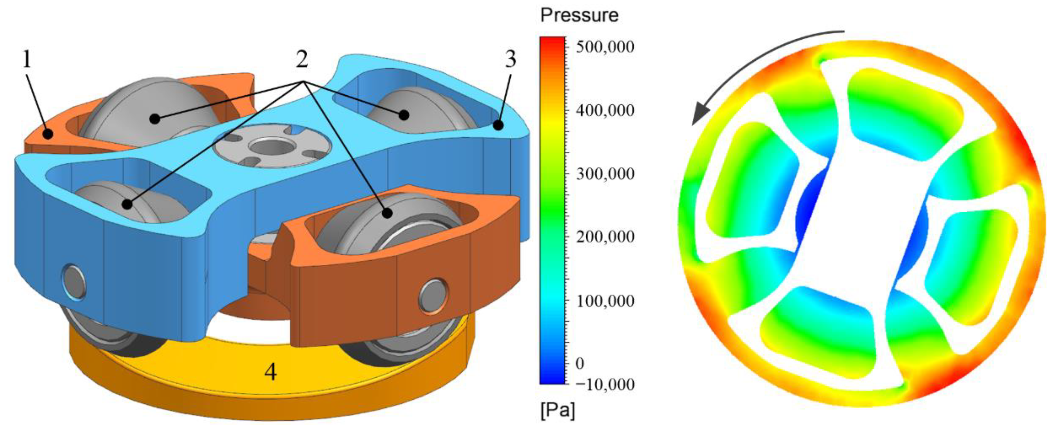
Due to the requirements of higher power-weight ratio for 2D pumps and higher resolution for 2D flowmeters, the designs of either pumps or flowmeters undergo a trend of applying higher rotational speeds. Moreover, to balance the inertial force produced by single 2D pistons, a more complicated 2D motion-converting mechanism was presented with two supports and four cone rollers, as shown in Figure 2 [10]. The above two improvements imply that a rotational speed-related phenomenon, so-called the churning loss, occurs at the stirring of the 2D motion-converting mechanism in hydraulic oil, and it accounts for unneglectable energy losses, especially at high rotational speeds. Due to the action of shear flow, the high-pressure zone appears at the outer of the rotor as shown in Figure 2, which prevents the rotor from rotating. In addition, because the rotor surface is pushing the oil to rotate, the produced drag torque has an increasing effect when rotational speeds climb high. The above two forces consist of the appearance of churning losses torque, which results in reducing the mechanical efficiency of 2D pumps or in increasing the pressure loss of 2D flowmeters. Meanwhile, since the axial reciprocation motion of active components happens simultaneously with rotation, the fluid motion around 2D motion-converting mechanisms includes a radical rotation flow and an axial reciprocation flow, resulting in more complicated churning losses, hence the need for a deep research.
The churning loss is more well-known in the studies of the efficiency of gear systems, where it is defined as the power loss when a gear runs in an oil bath, and its presentation is concluded as a load-independent result of the oil drag on the peripheries and faces of gears [16]. It is easy to deduct that the churning loss can occur in any rotating machinery. Unlike the studies on disks or gears submerged in fluids, which have been carried out for decades, whether in analytical modeling [17,18,19], CFD simulations [20,21,22], or experimental investigations [23,24], the churning loss phenomenon in hydraulic components has not been fully considered until it has become prominent when the rotational speed reaches a high level. Due to the high power-weight ratio requirement in the aeronautic and astronautic industries, hydraulic pumps, especially piston pumps, are designed for adapting super high rotational speeds. For example, the axial piston used in the A380 airplane is driven by a 15,000 rpm motor, whereas the one in the F-35 can be operated at a speed of up to 20,000 rpm [25]. Therefore, hydraulic pumps can be considered as the first hydraulic components to face the challenge of the effect of churning losses and to receive most of the attention of researchers. After Jang introduced the churning loss to a study of axial piston pumps in 1997 [26], Håkan stated that the churning loss is significant when the pressure is low and estimated it to be up to 20% of the total loss in axial piston pumps [27]. In the next decade, the reports of churning losses in hydraulic pumps have been rare until many researchers have started focusing on the energy losses of pumps when operated at high rotational speeds [28,29]. Ivantysynova and her group established a mathematical model with the assumption of laminar flow to predict the churning losses in the cylinder block, pistons, and slippers of axial piston pumps, and they validated their model with a series of experiments [30]. Afterwards, a churning losses model was added to a temperature field model to estimate the steady temperature of outlets and pump shells at given inlet temperatures [31]. Also, Zhang studied the primary distribution of churning losses and through experimental results concluded that the cylinder block rotation can lead to far greater churning losses than pistons and slippers [25]. He also applied his accurate model for predicting the steady temperature of EHA pumps [32]. Huang started to use CFD simulations to evaluate the churning losses in a 2D motion-converting mechanism in a high-speed 2D piston pump [15]. In his research, the rotating parts, two supports, and four cone rollers were simplified into a cross-like structure, as shown in Figure 2, to save the calculation time. The solutions of the mathematical models and CFD simulations well fitted the experimental results when the rotational speed was beyond 8000 rpm, but they had an apparent difference hereafter. After a period of research, Zhang concluded that in axial piston pumps, the rotation of cylinder products results in more churning losses because their fluid field is affected by the turbulence flow occurring around the pistons at high rotational speeds. Therefore, he used an insert settled around the cylinders to prevent the fluid turbulence caused by the pistons [33].
The churning loss situation in a 2D motion-converting mechanism in Huang’s previous research was quite different from that of axial piston pumps, and it was mainly caused by the stirring of the active parts in the oil [15]. When the rotational speed was high, the active parts were acting like four blades or impellers. However, because the 2D motion-converting mechanism not only converted motions but also transferred power and bear load pressures, the strength requirement and the mounting dimensions of the standard parts, such as bearings, make it hard to optimize the structures of supports and cone rollers. Therefore, a new 2D motion-converting mechanism structure was proposed in this paper with the same pump displacement and installation parameters of the older mechanism [15]. Subsequently, a series of CFD simulations were carried out to specifically obtain the churning loss and theoretically compare it with that of the former mechanism, and they additionally included the axial motion of the active parts in oil. Afterward, a test rig was set up to verify the simulation results and comply a comparative test. Finally, an analysis and discussion of the differences between the calculation and experimental results were put forward to more deeply investigate the churning loss.
2. Methods
2.1. Architecture and Numerical Modeling
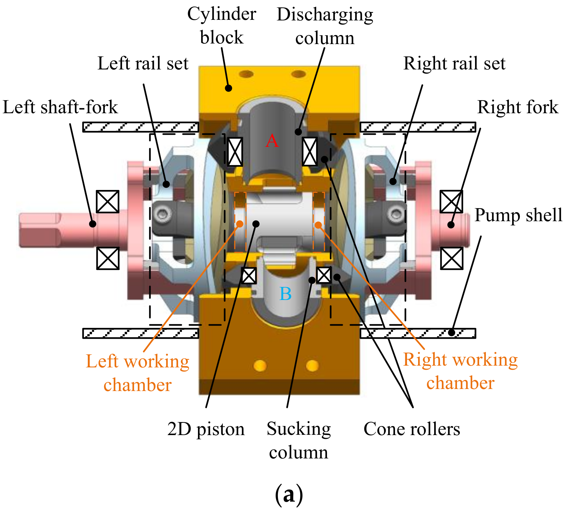
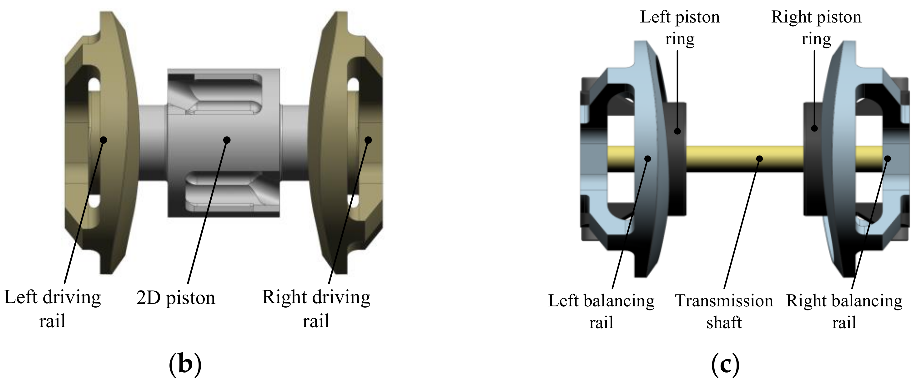
The last generation of 2D motion-converting mechanisms, which were applied in both 2D pumps and 2D flowmeters [10,14], adopts a fixed cam guiding rail and pairs of active cone rollers. Contrarily, the new 2D motion-converting mechanism makes the cone rollers fixed on the cylinder, where the cam guiding rails are the active parts rotating and reciprocating in the oil chamber, as shown in Figure 3. More specifically, compared with the last 2D pump design in reference [10], as shown in Figure 2, the unique change here was that the new 2D pump had pairs of cone rollers fixed on the cylinder block in addition to cam guiding rails fixed on the ends of both the driving and balancing sets. The reciprocating stroke of the 2D piston keeps the same as well as the pump’s displacement for every stroke. Since the same working principle was introduced in references [10,15], the distribution function was still provided through the windows and the rotating slots on the rotating 2D piston, whereas the opposite reciprocation motion from the 2D piston and piston rings provides the discharging and sucking functions.
Figure 4 more clearly shows the structure of the new 2D motion-converting mechanism. The driving rail is inside the balancing rail, and they keep a simultaneous rotational speed due to the fork. Meanwhile, it is critical to notice that the two rails can move freely in the axial direction, leading to the independent reciprocating motions of the driving and balancing sets. Therefore, despite the influence of the forks, the churning loss in this new 2D pump is mainly from the rotation and possibly from the relative reciprocating motion of the new 2D motion-converting mechanism.
2.2. Numerical Strategy
Computational fluid dynamic models based on the Navier–Stokes equation and the finite volume method are widely employed to obtain the motion characteristics of fluids in fluid machines, including churning loss calculations. The Navier–Stokes equation is the fundamental description in the numerical simulation of the fluid field, and its vector expression can be written as follows:
where is the fluid density, is the flow speed, is the acceleration of gravity, is the pressure, and is the dynamic viscosity coefficient.
To consider the potential occurrence of turbulence in a fluid field when the rotational speed is high, the k-ε model needs to be added during the pre-post process. In comparison with the standard k-ε model, the RNG k-ε model has higher accuracy due to the additional condition of the e equation, and it also considers the turbulent vorticity [34,35]. Hence, the RNG k-ε model is more suitable in the calculation of turbulence here rather than the Standard k-ε model. For the solution of the functions, the SIMPLE scheme was used for the Navier–Stokes equation.
2.3. Meshing Process and Boundary Conditions
Since the two rotors are symmetrically designed on the two ends of one 2D piston and are operated under the same working conditions, where each rotor consists of a driving rail and a balancing rail, it is reasonable to carry out a CFD simulation on one rotor to reduce the calculation time. As shown in Figure 5, the 3D model of one rotor demonstrates the rotator’s geometry, walls, and fluid zone. The dimensions of the whole 3D model are consistent with the actual design and listed in Table 1 with other critical parameters.
Due to the consideration of time tern in the N-S equation, the simulation uses the SIMPLE scheme to carry out instantaneous calculations. In particular, due to the consideration of time tern in equation 1, the unstructured tetrahedral mesh was used through the commercial software ICEM-CFD, an integrated grid, which is set without an interface [15], was applied to guarantee good continuity, and the smoothing method was adopted to simulate the rotation with various rotational speeds by writing UDFs in the commercial software Fluent. Since the axial motion of the rotator was not considered in the last research, the authors attempted to consider the influence of the axial relative motion of the two rails on the churning loss. Hence, two independent walls were, respectively, set for the driving rail and balancing rail to ensure that they have a relative reciprocating motion and the same rotational speed during the simulation. When the grid quality is at a similar level, the grid number is of great importance for accurately capturing microflow structures. The partial refine method is used to dramatically reduce the grid number based on the same grid quality for saving computing resources and time. The cross-sections in Figure 6a illustrate the partially refined grids with 0.27 million grid numbers in total. Because the grid sizes around the moving walls are the same, the time steps of the two grids are set as the time for the new rotor to rotate 0.1 degrees and the total time of two grids is as same as the time for the new rotor to rotate a complete circle. Besides, it should be noted that the churning losses torque is large and unconverged when the simulation is started initially. When the churning losses torque is eventually stabilized, the data of the new rotor rotating for 360 degrees are finally recorded as the simulation results.
Before the formal simulation, a comparison of the capture abilities between the 1 million global grids and 0.27 million partial refined grids was carried out in advance. The simulation calculations on two grids were preformed independently, and the results shown in Figure 7 indicate the feasibility of the partial refine method in this case.
3. Numerical Calculation
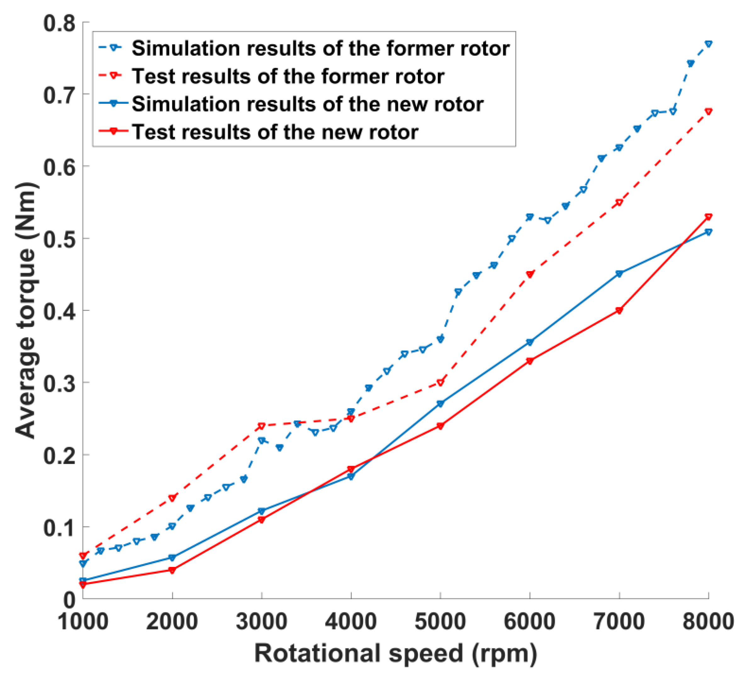
Based on the above settings, a series of CFD simulations were carried out at rotational speeds ranging from 1000 rpm to 8000 rpm. Then the pressure distribution of the new rotor can be obtained by post-processing. The churning losses torque of the new rotor can be calculated by integrating circumferential moment acting on the new rotor surface as the product of the circumferential force and the arm length from the point of application to the center of rotation. Figure 8 draws the calculation results of either new rotor or the former rotor [15] as a comparison. In the simulation, it could be observed that the new rotor has less churning loss torques than the former rotor and that the difference maintains an increasing enlargement. When the rotational speed reached 8000 rpm, the former rotor needed 0.77 Nm to stir the oil, but the torque for the new rotor was only 0.51 Nm.
More specifically, the pressure distributions on the two rotors were demonstrated at the two rotational speeds of 1000 rpm and 8000 rpm, as shown in Figure 9. Compared with the former rotor, the pressure distribution on the new rotor was much smoother and had a lower peak value at both rotational speeds. Meanwhile, the new rotor was certainly smaller than the former one since the reciprocating stroke of the 2D piston, the pump’s displacement, and rated working pressure were all the same. The smaller radial size, which indicates a larger gap between the outline of the rotor and the inner wall of the cylinder, resulted in a smaller shearing flow on the new rotor. In our study, the shearing flow took great responsibility for generating churning loss torque, especially at high rotational speeds.
The driving and balancing rails in the new rotor had relative axial motions in oil, leading to extra turbulence when the rotational speed was high. It is reasonable to analyze the effect of the axial motions to more clearly understand the churning loss torque. The comparative simulation results were demonstrated at 1000 and 8000 rpm, as shown in Figure 10. It can be seen that the difference between the simulation results with and without considering the axial motion is minor when the rotational speed is low. Although the difference is getting obvious when the rotational speed is at 8000 rpm, it is still acceptable to neglect the axial motion’s influence during the experiments of churning losses.
4. Experimental Results and Discussion
A churning loss test rig was assembled, as shown in Figure 11a, and it is mainly divided into three parts: stirring oil part, torque/speed sensor, and electric motor. As shown in Figure 11b, the test rotor stirs oil in the mid of a plastic test chamber’s inner space, which provides the same size of the actual working space of the rotor in the pump. To simplify the manufacturing of the tested new rotor, the driving rail was solidly fixed to the balancing rail for experiments, as shown in Figure 11c. The new rotor was solidly supported by a shaft and was connected to the torque/speed sensor through a coupling. The shut-off valve was used to fulfill the test chamber with oil and to exhaust air. The churning loss torque was monitored by the torque/speed sensor with a range from 0 to 10 Nm, an accuracy of ±0.1%, and a rotational speed upper limit of 18,000 rpm. The whole test rig was driven using a 30-kW three-phase asynchronous electric motor that can provide various rotational speeds with a maximum speed of 20,000 rpm.
In comparison with the previous research, the same experimental conditions were applied in this experiment, and they were consistent with the boundary conditions during the CFD simulation, as shown in Table 2.
Before filling with oil, the new rotor was first rotated in air with rotational speeds ranging from 1000 to 8000 rpm to obtain the mechanical losses during the transmission chain so as to have a clear background. The experimental results of the background torque are shown in Figure 12, and they were subtracted during the calculation of the experimental churning loss torques.
During the experiments, every test was started at the same room temperature (around 20 °C, controlled by air conditioning), and the target rotational speed was reached as soon as possible to prevent any decrease in the oil viscosity, which can be caused by any increase in temperature. The red and blue solid lines in Figure 13 show the experimental results of the new rotor and the obtained simulation results from the previous section, respectively. Two curves were very consistent with each other during various rotational speeds. Compared with the results (dash lines) of the former rotor, it can be seen that the new rotor gained less churning loss torques, especially when the rotational speed was high.
More specifically, the churning loss torque distributions at the rotational speeds of 1000 rpm and 8000 rpm were plotted, as shown in Figure 14. After repeating three times, the measured torques were around 0.02–0.03 Nm when the rotational speed was 1000 rpm, which well fits the simulation results. At the side of the high rotational speed (8000 rpm), the repeated measured torques stably ranged from 0.5 to 0.55 Nm when the simulation results had a small oscillation.
5. Conclusions
In this study, to reduce the churning losses occurring in either 2D pumps or 2D flowmeters, a new 2D motion-converting mechanism was presented with a detailed description of its architecture and working principles. Afterwards, considering its comparability with the former 2D motion-converting mechanism proposed in our previous research, a 3D structure model of the new 2D motion-converting mechanism was built for a 2D piston pump with the same design parameters. By highlighting the driving rail and balancing rail as the new rotor, a CFD simulation model was established to perform a comparison with the simulation results of the former rotor. Subsequently, a churning loss test rig was built to verify the feasibility of the CFD simulation, and, correspondingly, compete with the experimental results of the former rotor. According to the above-mentioned research, the following conclusions were put forward:
- During the pre-processing of the CFD simulation, a partially refined method was applied to decrease the number of mesh grids to 0.27 million, which could nearly reach the same simulation result of the original 1 million grid number, and, as a result, save the calculation time.
- Although the driving and balancing rails had a relative axial motion, the simulation results indicated that the axial motion of the rails was irrelevant with the change in the churning loss. Hence, the axial motion can be neglected when designing the tests, which is meaningful for the further research.
- The simulations and experimental results showed that compared with the former rotor, the new rotor resulted in a successful reduction in the churning loss at the full span of the rotational speeds. One main reason is that the new rotor had a smaller diameter, meaning that the gap between the outline of the new rotor and the inner wall of the cylinder was larger. The generated force from the shear flow in this gap was lowered down. Besides, there was a crack between the supports of the two rails, which also decreased the face of the blade and, thus, decreased the pressure drag when the supports pushed the fluid to rotate.
Author Contributions
Under supervision by J.R., C.D. developed mathematical modeling and wrote the manuscript; Y.H. performed calculations and data analysis; L.Z. performed design. All authors have read and agreed to the published version of the manuscript.
Funding
This research was funded in part by the National Natural Science Foundation of China, grant number 51805480, in part by the National Key Research and Development Program of China, grant number 2019YFB2005201, and in part by the Zhejiang Provincial Natural Science Foundation, grant number LY21E050013.
Conflicts of Interest
The authors declare no conflict of interest.
References
- Chapple, P. Principles of Hydraulic Systems Design; Momentum Press: New York, NY, USA, 2015. [Google Scholar]
- Ruan, J.; Ukrainetz, P.R.; Burton, R. Frequency domain modelling and identification of 2D digital servo valve. Int. J. Fluid Power 2000, 1, 49–59. [Google Scholar] [CrossRef]
- Ruan, J.; Burton, R.; Ukrainetz, P.; Xu, Y. Two-dimensional pressure control valve. Proc. Inst. Mech. Eng. Part C J. Mech. Eng. Sci. 2001, 215, 1031–1038. [Google Scholar] [CrossRef]
- Ruan, J.; Burton, R.; Ukrainetz, P. An investigation into the characteristics of a two dimensional “2D” flow control valve. J. Dyn. Sys. Meas. Control 2002, 124, 214–220. [Google Scholar] [CrossRef]
- Zibin, X.; Jianqing, M.; Yingguo, F.; Jiping, B.; Jian, R. Height frequency electro-hydraulic vibration exciter with 2D valve. In Proceedings of the 2008 2nd International Symposium on Systems and Control in Aerospace and Astronautics, Shenzhen, China, 10–12 December 2008; pp. 1–4. [Google Scholar]
- Ren, Y.; Ruan, J. Output waveform analysis of an electro-hydraulic vibrator controlled by the multiple valves. Chin. J. Mech. Eng. 2014, 27, 186–197. [Google Scholar] [CrossRef]
- Zhao, W.; Ruan, J. Experimental Study of the Dynamic Properties of 2D Servo Valve with Different Pilot Structure. In Applied Mechanics and Materials; Trans Tech Publications Ltd.: Laubisrutistr, Switzerland, 2014. [Google Scholar]
- Zuo, X.; Liu, G.; Zhang, S.; Li, S.; Ruan, J. Design and Characteristics Analysis of Bourdon Tube Pressure Feedback for 2D Pressure Servo Valve. Comptes Rendus Acad. Bulg. Sci. 2018, 71, 92–98. [Google Scholar]
- Zheng, F.-X.; Li, S.; Ding, C.; Zhao, J.-T.; Ruan, J. Theoretical and experimental research on the cartridge two-dimensional (2D) electro-hydraulic servo valve. Proc. Inst. Mech. Eng. Part C J. Mech. Eng. Sci. 2021, 13, 1687814021996532. [Google Scholar]
- Huang, Y.; Ruan, J.; Zhang, C.; Ding, C.; Li, S. Research on the Mechanical Efficiency of High-Speed 2D Piston Pumps. Processes 2020, 8, 853. [Google Scholar] [CrossRef]
- Jin, D.-c.; Ruan, J.; Li, S.; Meng, B.; Wang, L.-f. Modelling and validation of a roller-cam rail mechanism used in a 2D piston pump. J. Zhejiang Univ. Sci. A 2019, 20, 201–217. [Google Scholar] [CrossRef]
- Shentu, S.; Ruan, J.; Qian, J.; Meng, B.; Wang, L.; Guo, S. Study of flow ripple characteristics in an innovative two-dimensional fuel piston pump. J. Braz. Soc. Mech. Sci. Eng. 2019, 41, 464. [Google Scholar] [CrossRef]
- Xing, T.; Xu, Y.; Ruan, J. Two-dimensional piston pump: Principle, design, and testing for aviation fuel pumps. Chin. J. Aeronaut. 2019, 33, 1349–1360. [Google Scholar] [CrossRef]
- Ding, C.; Zhu, Y.; Liu, L.; Tong, C.; Ruan, J. Research on a Novel Flowmeter With Parallel Two-Dimensional Pistons as Its Metering Units. IEEE Access 2019, 7, 110912–110927. [Google Scholar] [CrossRef]
- Huang, Y.; Ding, C.; Wang, H.; Ruan, J. Numerical and experimental study on the churning losses of 2D high-speed piston pumps. Eng. Appl. Comput. Fluid Mech. 2020, 14, 764–777. [Google Scholar]
- Stavytskyy, V.; Nosko, P.; Fil, P.; Karpov, A.; Velychko, N. Load-independent power losses of gear systems: A review. Teka Kom. Motoryz. Energetyki Rol. 2010, 10, 205–213. [Google Scholar]
- Changenet, C.; Velex, P. A model for the prediction of churning losses in geared transmissions—preliminary results. J. Mech. Des. 2007, 129, 128–133. [Google Scholar] [CrossRef]
- Daily, J.W.; Nece, R.E. Chamber dimension effects on induced flow and frictional resistance of enclosed rotating disks. J. Basic Eng. 1960, 82, 217–230. [Google Scholar] [CrossRef]
- Luke, P.; Olver, A. A study of churning losses in dip-lubricated spur gears. Proc. Inst. Mech. Eng. Part G J. Aerosp. Eng. 1999, 213, 337–346. [Google Scholar] [CrossRef]
- Arisawa, H.; Nishimura, M.; Imai, H.; Goi, T. CFD simulation for reduction of oil churning loss and windage loss on aeroengine transmission gears. In Turbo Expo: Power for Land, Sea, and Air; ASME: Orlando, FL, USA, 2009. [Google Scholar]
- Kodela, C.; Kraetschmer, M.; Basa, S. Churning loss estimation for manual transmission gear box using CFD. SAE Int. J. Passeng. Cars-Mech. Syst. 2015, 8, 391–397. [Google Scholar] [CrossRef]
- Liu, H.; Jurkschat, T.; Lohner, T.; Stahl, K. Determination of oil distribution and churning power loss of gearboxes by finite volume CFD method. Tribol. Int. 2017, 109, 346–354. [Google Scholar] [CrossRef]
- Chothani, H.G.; Maniya, K.D. Experimental investigation of churning power loss of single start worm gear drive through optimization technique. Mater. Today Proc. 2020, 28, 2031–2038. [Google Scholar] [CrossRef]
- Seetharaman, S.; Kahraman, A.; Moorhead, M.; Petry-Johnson, T. Oil churning power losses of a gear pair: Experiments and model validation. J. Tribol. 2009, 131, 022202. [Google Scholar] [CrossRef]
- Zhang, J.; Li, Y.; Xu, B.; Pan, M.; Lv, F. Experimental Study on the Influence of the Rotating Cylinder Block and Pistons on Churning Losses in Axial Piston Pumps. Energies 2017, 10, 662. [Google Scholar] [CrossRef] [Green Version]
- Jang, D.S. Verlustanalyse an Axialkolbeneinheiten; in IFAS; RWTH Aachen University: Aachen, Germany, 1997. [Google Scholar]
- Olsson, H. Power losses in an axial piston pump used in industrial hydrostatic transmissions. In Proceedings of the Eighth Scandinavian International Conference on Fluid Power, Tampere, Finland, 7–9 May 2003. [Google Scholar]
- Chao, Q.; Zhang, J.; Xu, B.; Huang, H.; Zhai, J. Effects of inclined cylinder ports on gaseous cavitation of high-speed electro-hydrostatic actuator pumps: A numerical study. Eng. Appl. Comput. Fluid Mech. 2019, 13, 245–253. [Google Scholar] [CrossRef] [Green Version]
- Zhang, B.; Ma, J.; Hong, H.; Yang, H.; Fang, Y. Analysis of the flow dynamics characteristics of an axial piston pump based on the computational fluid dynamics method. Eng. Appl. Comput. Fluid Mech. 2017, 11, 86–95. [Google Scholar] [CrossRef] [Green Version]
- Zecchi, M.; Mehdizadeh, A.; Ivantysynova, M. A novel approach to predict the steady state temperature in ports and case of swash plate type axial piston machines. In Proceedings of the 13th Scandinavian International Conference on Fluid Power, Linköping, Sweden, 3–5 June 2013; Linköping University Electronic Press: Linköping, Sweden, 2013. [Google Scholar]
- Shang, L.; Ivantysynova, M. Port and case flow temperature prediction for axial piston machines. Int. J. Fluid Power 2015, 16, 35–51. [Google Scholar]
- Zhang, J.; Li, Y.; Xu, B.; Chen, X.; Pan, M. Churning losses analysis on the thermal-hydraulic model of a high-speed electro-hydrostatic actuator pump. Int. J. Heat Mass Transf. 2018, 127, 1023–1030. [Google Scholar] [CrossRef]
- Zhang, J.; Li, Y.; Xu, B.; Pan, M.; Chao, Q. Experimental study of an insert and its influence on churning losses in a high-speed electro-hydrostatic actuator pump of an aircraft. Chin. J. Aeronaut. 2019, 32, 2028–2036. [Google Scholar] [CrossRef]
- Launder, B.E.; Spalding, D.B. The numerical computation of turbulent flows. In Numerical Prediction of Flow, Heat Transfer, Turbulence and Combustion; Pergamon Press: Oxford, UK, 1983; pp. 96–116. [Google Scholar]
- Yakhot, V.; Orszag, S.; Thangam, S.; Gatski, T.; Speziale, C. Development of turbulence models for shear flows by a double expansion technique. Phys. Fluids A Fluid Dyn. 1992, 4, 1510–1520. [Google Scholar] [CrossRef] [Green Version]
Figure 1.
Schematic of a two-dimensional (2D) piston mechanism [10]: (1) Cone roller; (2) Cam guiding rail; (3) Cylinder; (4) Limit block; (5) Transmission shaft; (6) 2D piston; (a) Discharge windows; (b) Intake windows; (c) Distributing slots.
Figure 1.
Schematic of a two-dimensional (2D) piston mechanism [10]: (1) Cone roller; (2) Cam guiding rail; (3) Cylinder; (4) Limit block; (5) Transmission shaft; (6) 2D piston; (a) Discharge windows; (b) Intake windows; (c) Distributing slots.

Figure 2.
Structure of the 2D motion converting mechanism and its simplified simulation model for studying churning losses [10,15]: (1) The driving rollers support; (2) Cone rollers; (3) Balancing rollers support; (4) Cam guiding rail (fixed with the cylinder).

Figure 3.
Mechanical structure of a 2D piston pump with the new 2D motion-converting mechanism: (a) Overview; (b) Driving set; (c) Balancing set.
Figure 3.
Mechanical structure of a 2D piston pump with the new 2D motion-converting mechanism: (a) Overview; (b) Driving set; (c) Balancing set.


Figure 4.
Structure of the new 2D motion-converting mechanism.

Figure 5.
Schematic representation of the rotor in the fluid zone.

Figure 6.
Cross sections of two grid numbers: (a) 0.27 million grid number; (b) 1 million grid number.
Figure 6.
Cross sections of two grid numbers: (a) 0.27 million grid number; (b) 1 million grid number.

Figure 7.
Comparison of the two grid numbers at the rotational speeds of (a) 1000 rpm and (b) 8000 rpm.
Figure 7.
Comparison of the two grid numbers at the rotational speeds of (a) 1000 rpm and (b) 8000 rpm.

Figure 8.
Comparison of the churning loss torques between the two rotors.

Figure 9.
Pressure distributions of the two rotors: (a) The new rotor at 1000 rpm; (b) The former rotor at 1000 rpm; (c) The new rotor at 8000 rpm; (d) The former rotor at 8000 rpm.
Figure 9.
Pressure distributions of the two rotors: (a) The new rotor at 1000 rpm; (b) The former rotor at 1000 rpm; (c) The new rotor at 8000 rpm; (d) The former rotor at 8000 rpm.

Figure 10.
Influence of the axial motion on the churning loss torque at (a) 1000 rpm and (b) 8000 rpm.
Figure 10.
Influence of the axial motion on the churning loss torque at (a) 1000 rpm and (b) 8000 rpm.

Figure 11.
Test rig of the churning loss: (a) Overview of the test rig; (b) Details of the stirring oil part; (c) Comparison of the two rotors.
Figure 11.
Test rig of the churning loss: (a) Overview of the test rig; (b) Details of the stirring oil part; (c) Comparison of the two rotors.


Figure 12.
The background torques.

Figure 13.
The churning loss torques of the new rotor and the former rotor.

Figure 14.
The torque distributions of the churning losses with different rotational angles: (a) at a rotational speed of 1000 rpm; (b) at a rotational speed of 8000 rpm.
Figure 14.
The torque distributions of the churning losses with different rotational angles: (a) at a rotational speed of 1000 rpm; (b) at a rotational speed of 8000 rpm.


Table 1.
Parameters of the fluid zone.
| Name | Value |
|---|---|
| Fluid field diameter | 66 mm |
| Fluid field length | 30 mm |
| Total length of balancing rail | 20 mm |
| Diameter of balancing rail | 53 mm |
| Total length of driving rail | 12 mm |
| Diameter of driving rail | 38 mm |
| Balancing rail length 1 | 6 mm |
| Balancing rail length 2 | 7 mm |
| Support thickness | 5 mm |
| Groove length | 10 mm |
| Groove width | 22 mm |
| Oil temperature | 20 °C |
| Oil density | 850 kg/m3 |
| Oil dynamic viscosity | 0.03893 kg/m-s |
| Rotational speed range | 1000–8000 rpm |
Table 2.
The experimental conditions.
| Name | Value |
|---|---|
| Pressure | 1.02 bar |
| Rotational speed | 1000–8000 rpm |
| Oil density | 850 kg/m3 |
| Oil viscosity | 45.8 × 10⁻⁶ m2/s |
| The diameter of test chamber | 66 mm |
| The length of test chamber | 30 mm |
Publisher’s Note: MDPI stays neutral with regard to jurisdictional claims in published maps and institutional affiliations. |
© 2021 by the authors. Licensee MDPI, Basel, Switzerland. This article is an open access article distributed under the terms and conditions of the Creative Commons Attribution (CC BY) license (http://creativecommons.org/licenses/by/4.0/).
Share and Cite
MDPI and ACS Style
Ding, C.; Huang, Y.; Zhang, L.; Ruan, J. Investigation of the Churning Loss Reduction in 2D Motion-Converting Mechanisms. Energies 2021, 14, 1506. https://0-doi-org.brum.beds.ac.uk/10.3390/en14051506
AMA Style
Ding C, Huang Y, Zhang L, Ruan J. Investigation of the Churning Loss Reduction in 2D Motion-Converting Mechanisms. Energies. 2021; 14(5):1506. https://0-doi-org.brum.beds.ac.uk/10.3390/en14051506
Chicago/Turabian StyleDing, Chuan, Yu Huang, Lichao Zhang, and Jian Ruan. 2021. "Investigation of the Churning Loss Reduction in 2D Motion-Converting Mechanisms" Energies 14, no. 5: 1506. https://0-doi-org.brum.beds.ac.uk/10.3390/en14051506
Note that from the first issue of 2016, this journal uses article numbers instead of page numbers. See further details here.