
Design and Implement of Three-Phase Permanent-Magnet Synchronous Wave Generator using Taguchi Approach


Department of Electrical Engineering, National Taiwan University of Science and Technology, Taipei 10607, Taiwan
*
Author to whom correspondence should be addressed.
Energies 2021, 14(7), 2010; https://0-doi-org.brum.beds.ac.uk/10.3390/en14072010
Submission received: 28 February 2021
/
Revised: 26 March 2021
/
Accepted: 31 March 2021
/
Published: 5 April 2021
(This article belongs to the Special Issue New Advances in Permanent Magnet Electrical Machines)
Abstract
:In this paper, the design and performance analysis of a high-efficiency permanent-magnet synchronous wave generator (PSWG) are presented. A systematic approach for the design of the outer rotor was proposed as a prototype model. The magnetic field, magnetic circuit characteristics, electrical characteristics of the generator, and optimal design parameters such as the pole–arc ratio and shoe outer length were determined using the Taguchi method, finite-element analysis (FEA) software, and rotor skewing techniques. The proposed six series and six parallel-connection winding configurations can provide an evenly distributed current for practical applications. A PSWG was designed and fabricated according to the proposed methodology. According to the experimental results by implementing the optimized design, the efficiencies of the proposed PSWG which used 3.6 Ω load at 300 rpm is 86.32% and the efficiency error between simulation and experiment is less than 1.8%. It verifies the feasibility of the proposed method to PSWG and the structural reliability optimization design.
1. Introduction
The demand for energy has significantly increased over recent years. Finding a stable alternative energy source, reducing the carbon emissions, and energy-saving technologies have become the focus of the sustainable development of countries with core issues at stake [1]. The renewable energy technologies include wind, solar photovoltaics, and hydropower. The power source of the wind power generation is mainly wind. Therefore, the choice of the plant site and effective transmission of the electricity to the system are very important. The development of China’s wind power industry and technology, the current situation, and the potential for further development and use are reported. [2]. The solar photovoltaics are limited by solar panels. Owing to the influences of weather factors such as the materials, sunshine time, irradiation angle, light intensity, and dust accumulation thickness, the development of power generation is limited and unstable. It cannot be used as a source of stable output power. The output performance and cost of a solar thermal power system have been analyzed [3]. In addition, the problems of low radiation levels, embodied energy costs, variability, and storage have been discussed.
Wave energy conversion devices are environmentally friendly. In addition, the seasonal change of sea waves is more consistent with the demand for electricity. The enormous amount of energy stored in ocean waves is being studied for commercial-scale production [4]. The global wave energy resources are abundant, particularly in the main wave energy range of 40 °N/S to 60 °N/S. The energy flow density can reach 30 to 70 kW/m. The World Energy Council has estimated that the global wave energy resources can reach 2 TW, equivalent to providing an energy of approximately 17,500 TWh per year [5]. A potential power of 37 GW exists in the Mediterranean Sea [6]. In Scotland, where the development of ocean wave power is more advanced, marine renewable energy devices (MREDs) have also been investigated in terms of ecology. The flow, water column and Benthic ECology 4D (FLOWBEC-4D) studies the environmental and ecological impacts of installing and operating wave and tidal energy devices [7]. The wave power system can be divided into two parts: collection and transmission systems. The main function of the former is to obtain wave energy, while that of the latter is to adjust waves with irregular amplitude changes and convert them by the mechanical resonance centralized power transfer to stabilize the power grid.
The permanent-magnet synchronous machine does not have commutator and carbon brush. The copper loss was lower than that of the induction machine. The brushed machine not only cause mechanical loss due to the friction between the carbon brushes and slip ring, but also the wear of the brushes can destroy the stability of the electric wave [8]. In terms of the ocean wave device, the generator should operate at a low speed [9]. Linear generators only absorb mechanical energy from unidirectional wave motion. However, it is still technically challenging to capture the ocean wave energy [10,11,12]. Synchronous generators can absorb and generate reactive power by adjusting the phase angle between the voltage and current, which will contribute to the power balance of the entire power grid [13]. Permanent-magnet synchronous machines play a pivotal role in the conversion of ocean energy, and have a good performance in converting ocean energy to electrical energy [14,15]. The applied concentrated winding could reduce the length of the coil. The manufacturing is easier and can effectively reduce the coil resistance and copper loss. In addition, the outer rotor structure has a high torque and good stability. This is suitable for low-speed and harsh marine environments. Considering the safety and economic efficiency, PSWG is preferred in this study.
The cogging torque, originated from shaft vibration and noise, particularly in low-speed direct-drive applications, is one of the primary drawbacks of these motors [16]. Analytical methods for minimization of the cogging torque in PM machines have been investigated [16,17,18]. Jiang et al. [19] applied a genetic algorithm to minimize the cogging torque for different skew patterns. Washington et al. [20] applied tooth pitching to a separate phase Modulated Pole Machines (MPM) to reduce the most prominent harmonics present in a three-phase MPM’s cogging torque.
For optimization problems, the best optimization combination can be obtained with a low number of experiments using the Taguchi’s method [21,22,23], which is a robust design method. The V-shaped permanent-magnet synchronous motor (PMSM) Taguchi’s method is effective for optimization. It increases the average torque and reduces the cogging torque [24,25]. It is also effective to improve the efficiency and reduce the cogging torque in a surface-mounted PMSM [26,27]. Another approach is to combine the Taguchi’s method with other design methods such as the design of experiment to simultaneously achieve the maximum efficiency and minimum cogging torque [28]. Lim et al. [29] applied the Taguchi method to optimal design of an interior permanent-magnet synchronous generator (IPSMG) for range the extended electric vehicle. The Taguchi model shows better performance in the cogging torque and torque ripple than the initial model. Reza et al. [30] proposed to optimize the design of permanent-magnet generators for wind power systems by combining Halbach array permanent magnets with Taguchi method. The objective is to reduce the cogging torque without affecting the average torque by modifying the stator-side parameters.
The objective of this study is to design a synchronous generator for wave power generation. The generator exhibits a high average torque output and low cogging torque, without an additional reducer. Section 2 describes the generator specifications and winding planning. The design and analysis of magnetic field characteristics and electrical transients are presented in Section 3. Section 4 presents comparison of the measurement and simulation results. Section 5 summarizes the results of this study.
2. Structure and Characteristics
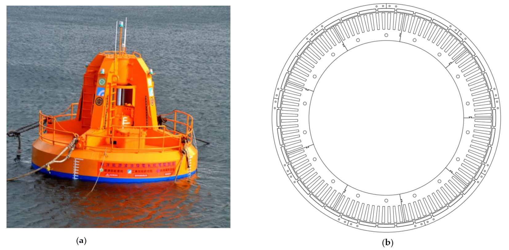
The basic principle of the floating-point absorber wave system is to use the top buoy to move up and down with the waves on the sea surface to drive the generator. Alternatively, it uses a linear motion to pressurize the medium that transmits energy, so that the hydraulic motor can be pumped to drive the generator. It can absorb wave energy from all directions and its external structure is shown in Figure 1a. The main advantages are the circular float design does not need to correspond to the wave direction and the anchor system is relatively simple to deploy. The material used is the most common 50 series 470 silicon steel sheet and N35 neodymium iron boron magnet, so that the cost can be taken into account when optimizing the design structure. The main goal of this study is to design a PSWG to be applied to the floating-point absorber wave system. A PSWG with 36 poles and 108 slots was selected in this study. The geometric structure of the three-phase permanent-magnet outer rotor synchronous generator is shown in Figure 1b. Table 1 lists the fundamental specifications of the prototype model. According to the experimental operation conditions, the electrical characteristics were simulated at a speed of 300 rpm. The stator uses 108 slots; each slot has 44 turns. The proposed PSWG mainly uses concentrated winding and can reduce the length of the coil. Each phase is matched with six series and six parallel methods, which is not only simple to manufacture but also can distribute the current. The rotor electromagnetic employs an embedded structure to improve the mechanical strength, which can retain the effective magnetic flux and reduce the higher harmonics of the air-gap magnetic flux. The proposed PSWG is an application structure of point absorption power generation, so that the inner and outer diameters of the rotor are set to 450 and 470 mm, respectively.
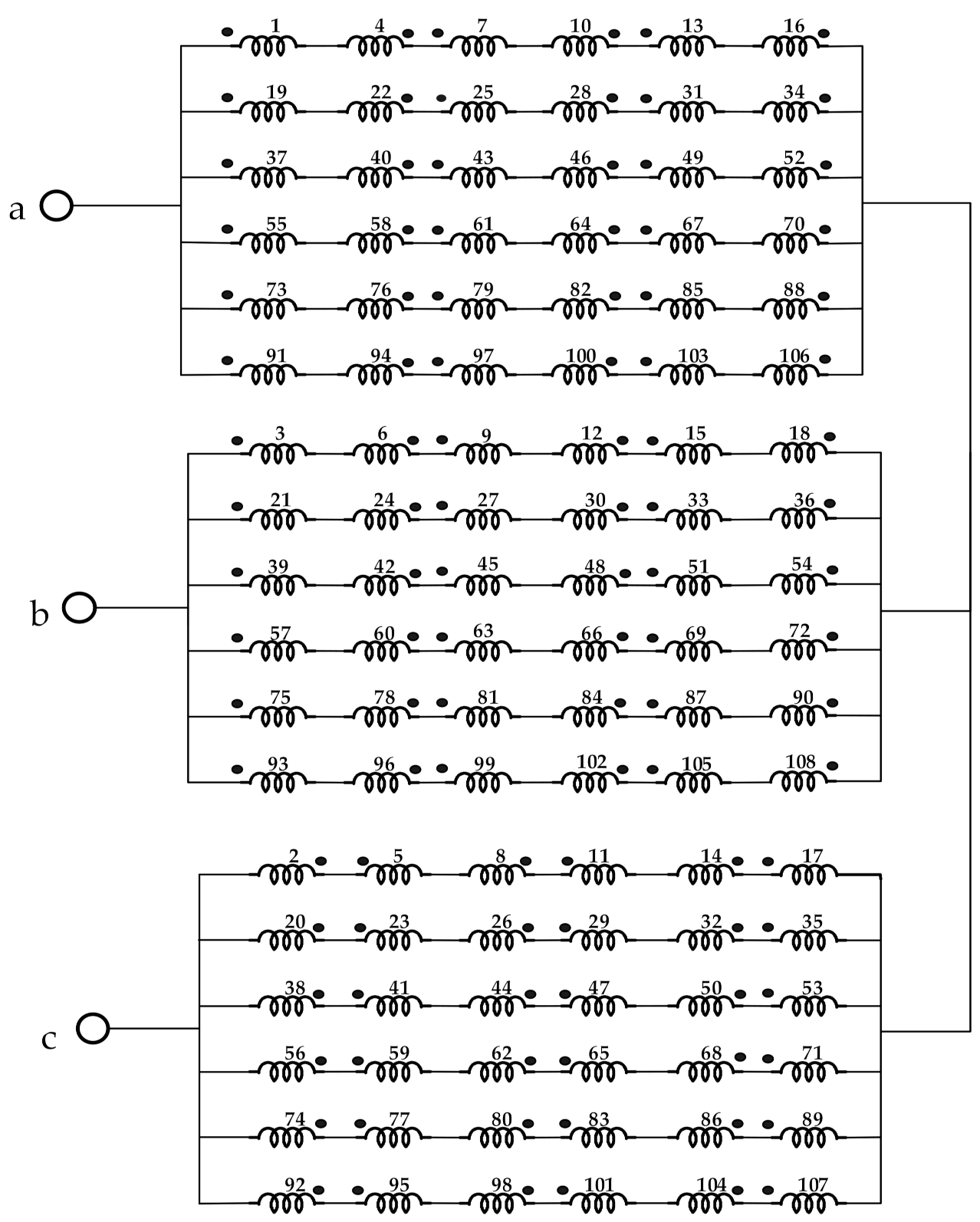
The overall mechanical angle (3.33°) of the PSWG winding of each slot can be calculated using Equation (1). Hence, the winding plan can be converted as 60° k using Equation (2). To achieve a three-phase balance, the angle of the winding connection should be 120°. Figure 2 shows a schematic of the PSWG winding, where a, b, c represents the three-phase structure.
: Mechanical angle; : Electrical angle; : Number of slots; : Number of poles; : Order of the slots.
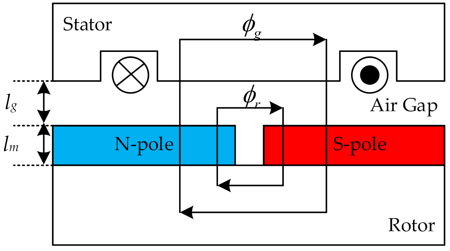
Before performing transient analysis, a magnetic circuit analysis of the generator should be conducted to ensure that there is no magnetic saturation phenomenon. Figure 3 demonstrates the magnetic flux path diagram of a surface permanent-magnet synchronous generator, which includes the stator, rotor, air gap, winding, the north and south magnetic poles. The total magnetic flux flow is from the N-pole through the air gap to the stator, and then returns to the S-pole, forming a closed magnetic flux loop [31].
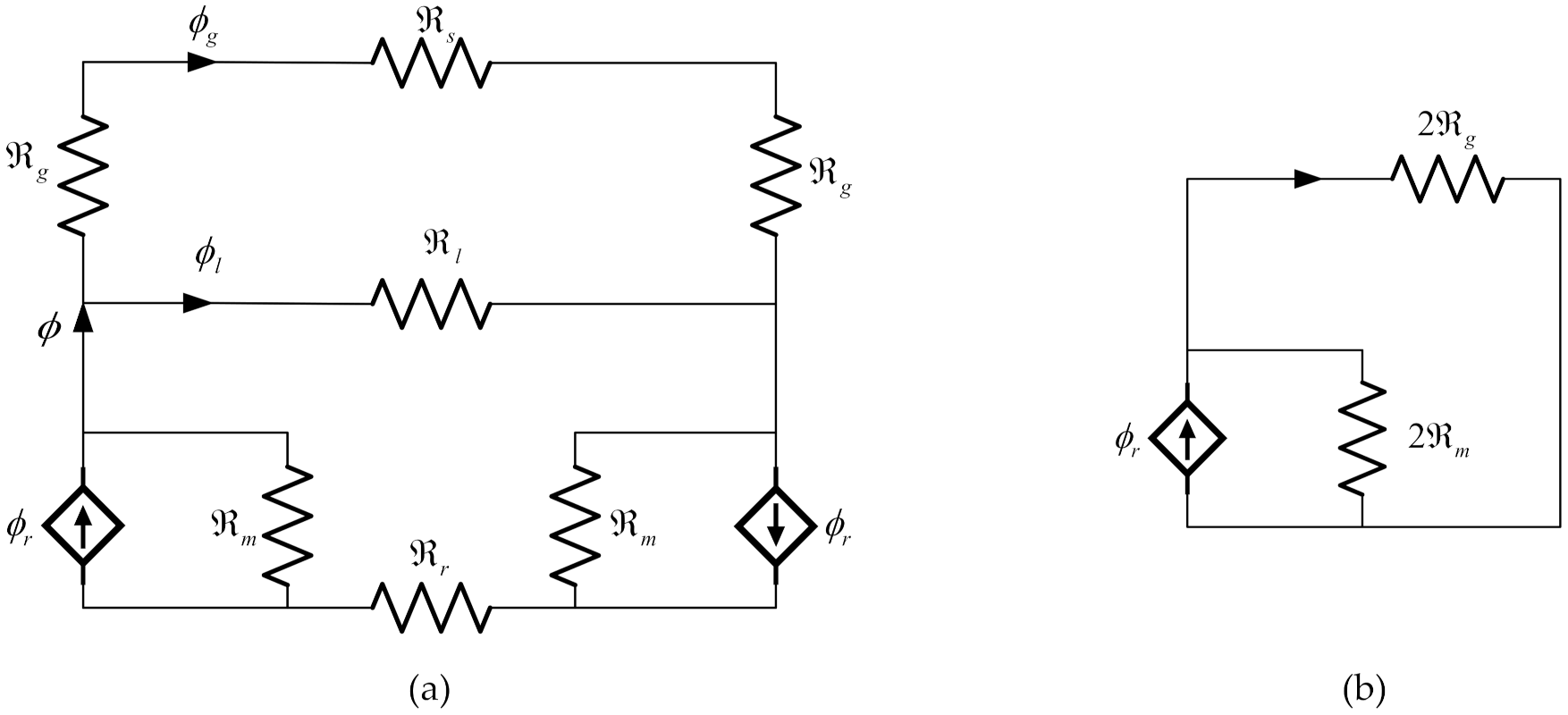
The magnetic flux path diagram shown in Figure 3 is equivalent to a magnetic circuit, as shown in Figure 4. The silicon steel sheet material and the width of the stator yoke used in the machine must be selected well to avoid magnetic saturation and magnetic flux leakage.
Passed through the air-gap flux could be written as and assumed that the leakage flux() is negligible. Therefore, a reluctance which in Figure 4a could be ignore. In addition, the reluctance of the stator ( and rotor of the machine are much smaller than the air gap of reluctance () So the reluctance of the silicon steel sheet is ignored to simplify the overall magnetic circuit, as shown in Figure 4b.
The magnetic flux can be derived as [31]:
Since the relationship between magnetic permeability () and air-gap magnetic flux density is nonlinear. When the is twice, the growth of air-gap magnetic flux density () is not proportional to twice. However, the can be used to find the relationship with the . Using the formula:
and:
Equation (3) becomes:
If all the magnetic flux leaving the magnet go into the stator through the air gap, without causing any leakage flux, then:
So, Equation (6) can be reformed as:
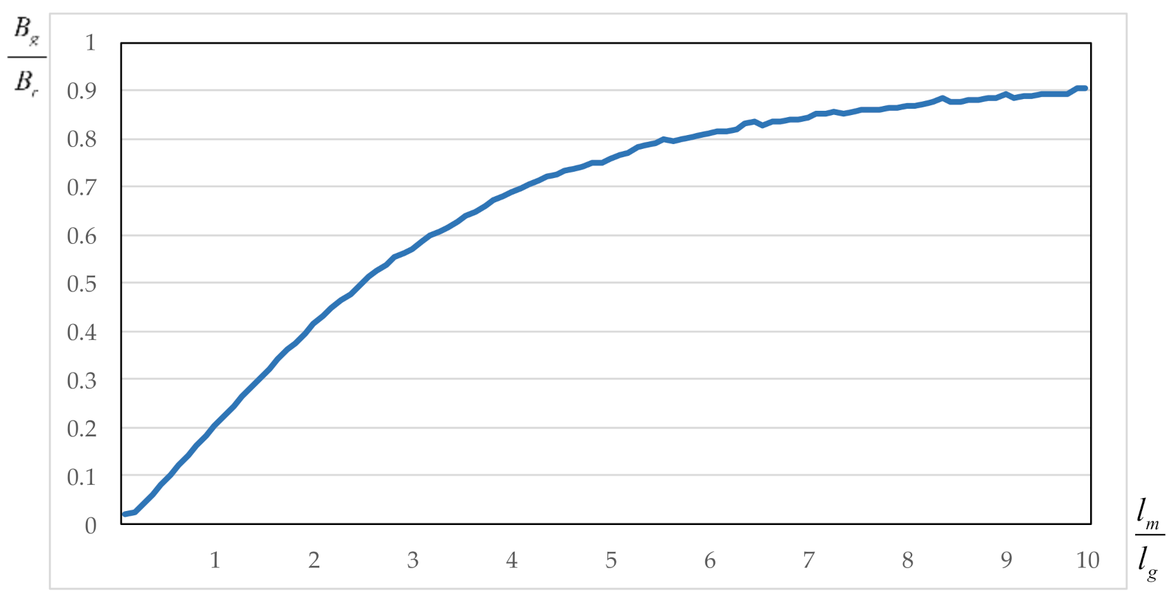
By proving the relationship between air-gap magnetic flux density and magnetic permeability, it can be known that the air-gap length and magnet thickness account for a very important part. If the air-gap length is too long, the overall machine performance will be low, and the magnetic flux density will be reduced. If the air-gap length is too short, the machine may vibrate at high speed, causing skew or magnet wear. The preferred ratio of air-gap length to magnet thickness is usually about 4-6 times, as shown in Figure 5. The length of the air gap also depends on the precision of the manufacturing process at the time, and it cannot be manufactured even if the design is too small. Therefore, the magnet thickness is usually changed to achieve the target ratio. The air-gap length in this study is set to 1.5 mm. According to formula (8), the thickness of the magnet is 4 times 6 mm.
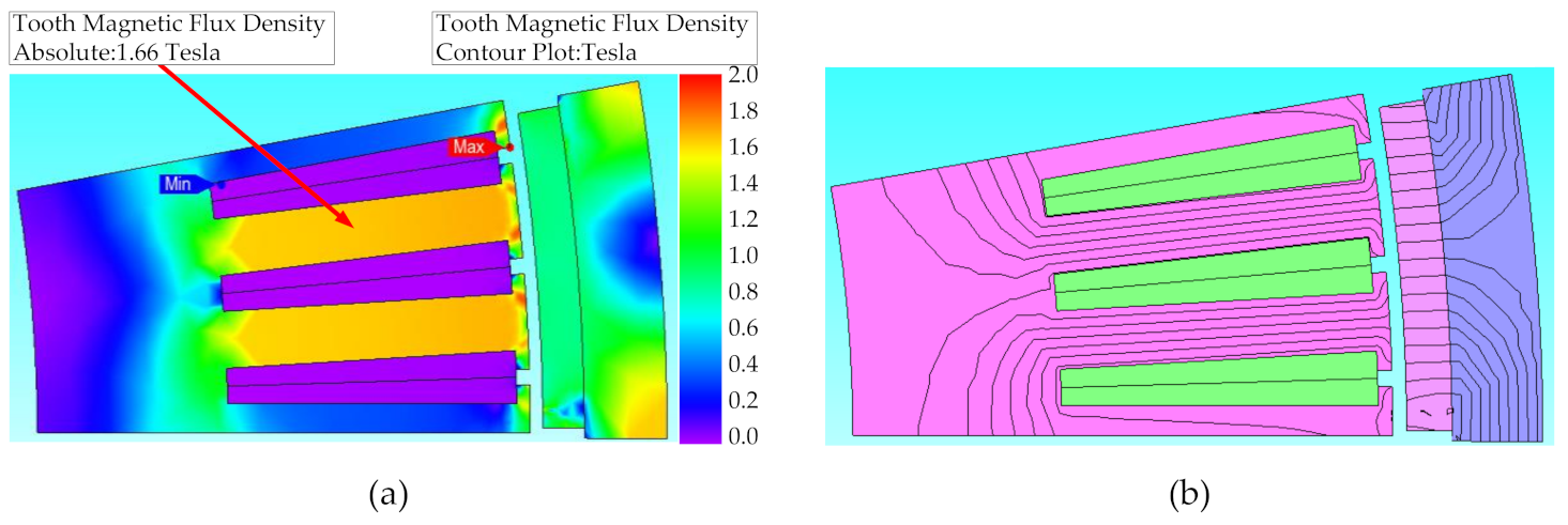
The electric characteristics such as the magnetic flux distribution and magnetic flux density can be analyzed using finite element analysis software, JMAG. As shown by the magnetic field flow without load in Figure 6a, the color closest to red indicates a higher magnetic flux density. Figure 6b shows that the PSWG does not exhibit magnetic flux leakage under these simulated conditions. The maximum magnetic flux density of approximately 1.66 T, lower than the magnetic saturation point of the silicon steel, occurred at the tooth part. It did not reach magnetic saturation at 1.85 T (50CS470). If the magnetic flux density is too high, the generator generates more heat and has a reduced efficiency.
3. Optimal Analysis Using Taguchi Method
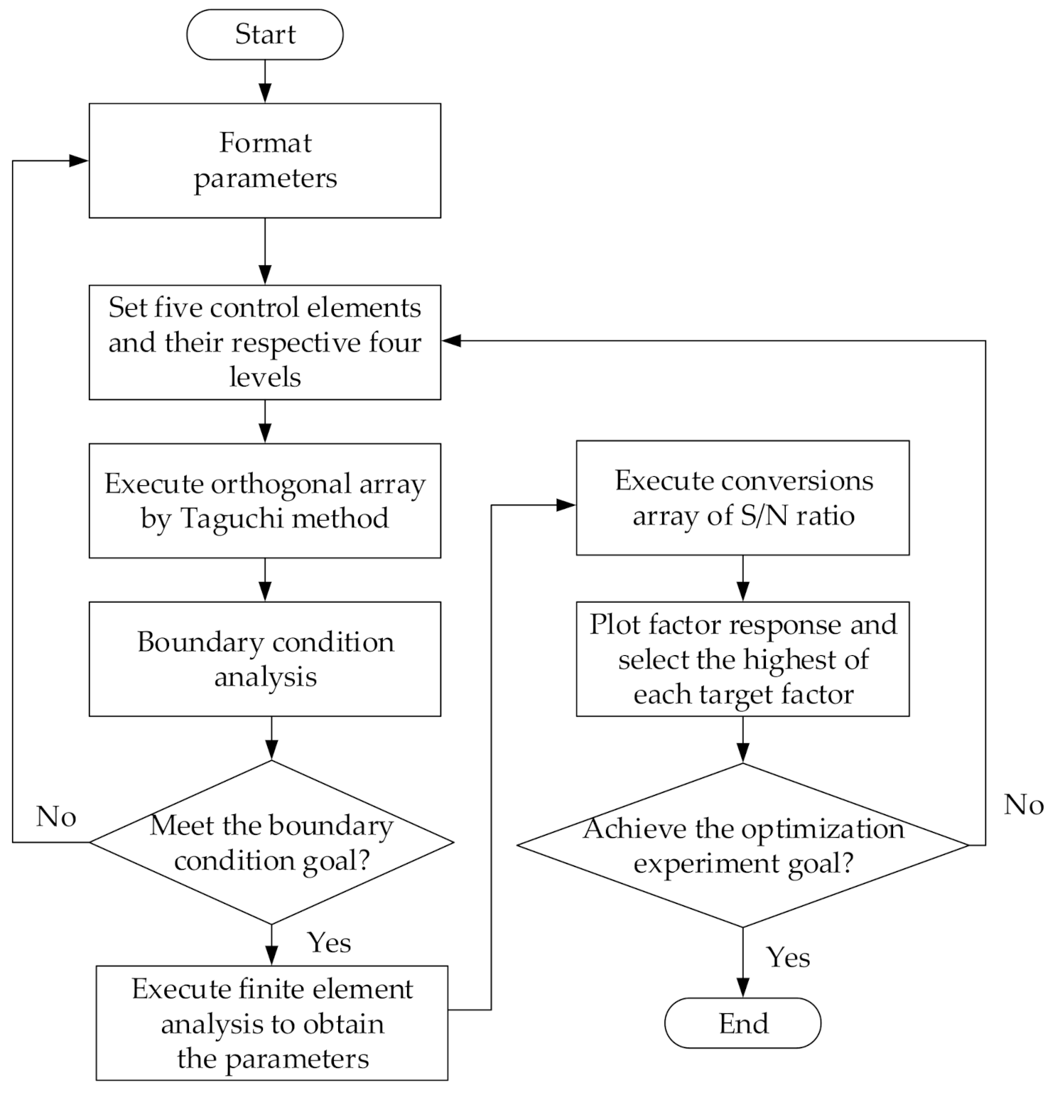
The Taguchi method has been widely used in generator design because it provides engineers with a systematic and effective way to manage numerical experiments and quickly obtain optimal parameters. Using the orthogonal array experimental design proposed by the Taguchi method, the effects of numerous different parameters or control factors on the performance characteristics can be analyzed in a condensed set of experiments. In this paper, a three-phase permanent-magnet synchronous wave generator using Taguchi’s method is presented. A flow chart of the optimization procedure is shown in Figure 7. The description of the optimization procedure is
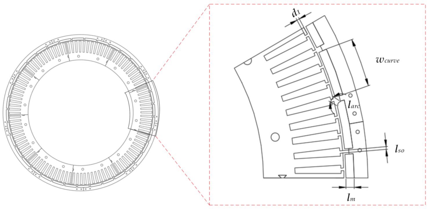
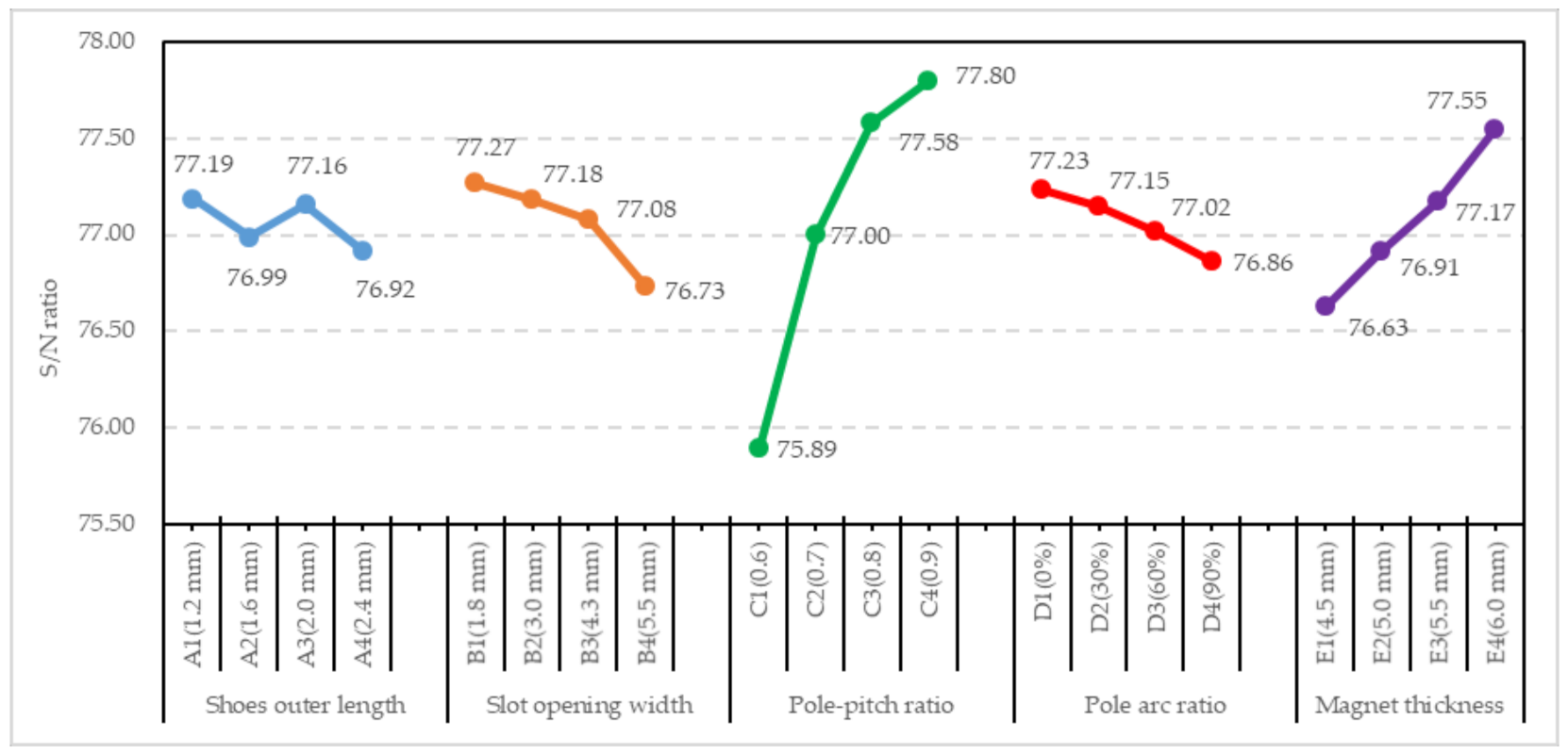
According to Figure 8 and Table 2, five parameters, shoe outer length, slot opening width, pole–pitch ratio, pole–arc ratio, and magnet thickness, are chosen as control factors, which are subdivided into four levels to yield 16 rows of data shown in Table 3 for the orthogonal array L16 to process 16 simulations with JMAG. The slot opening width and pole–arc ratio can reduce the cogging torque. The shoe outer length affects the slot ratio. The pole–pitch ratio and magnet thickness can effectively increase the output power. Each level of the factor is substituted into L16 and each cross test is modeled and analyzed according to the level assigned by the orthogonal table. The results of the cross experiment are converted into output power, as shown in Table 3.
One of the key features of the Taguchi method is the use of the signal-to-noise (S/N) ratio to transform the performance characteristics in the optimization process. The S/N ratio can be used to evaluate whether the experimental results are good for the experimental target, and then, through the factor response table and factor response chart, the optimization trend as a result of changing the factors can be evaluated. The generator performance considered in this study is mainly based on the output power obtained by the Taguchi method.
Among the experimental factors of the stator and rotor selected in this study, each item has an impact on the magnetic flux density of the stator, particularly the factors of the rotor, the path of the magnetic field lines and magnetic flux density of the back iron. For the larger-the-better (LTB) quality characteristic, the S/N ratio is defined as
Regarding the S/N ratio, a larger value implies better quality characteristics, as shown in Table 3. Table 3 indicates that the best S/N ratio among the 16 simulations was obtained during the 14th run (S/N = 78.20), with an outer power of 8126 W. Table 4 shows that the range (Level,max–Level,min) of Factor C is largest, so that its influence is larger than those of the other factors. In addition, Figure 9 shows that the shoe outer length, slot opening width, pole–pitch ratio, pole–arc ratio, and magnet thickness for the optimized S/N ratio are 1.2 mm (A1), 1.8 mm (B1), 0.9 (C4), 0% (D1), and 6 mm (E4), respectively.
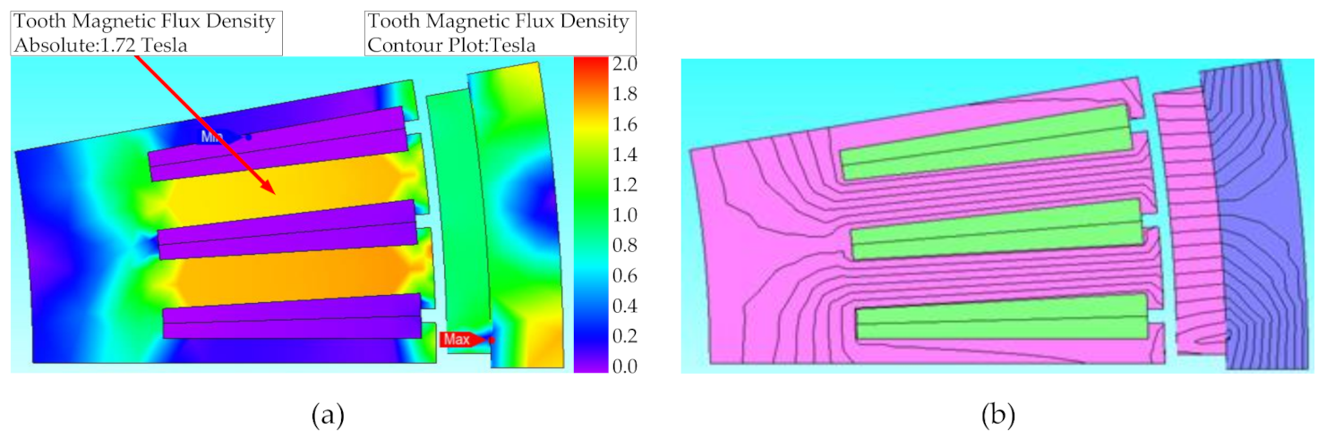
Figure 10 shows that the maximum magnetic flux density of the proposed PSWG on the stator silicon steel sheet is approximately 1.72 T, observed on the stator teeth. Its magnetic flux density is lower than the magnetic saturation point of 1.85 T (50CS470).
4. Performance Analysis and Discussion
4.1. Product Implementation
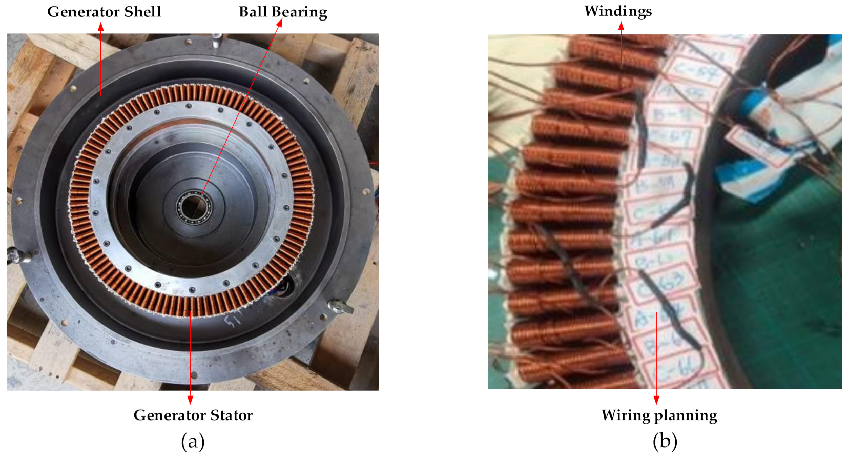
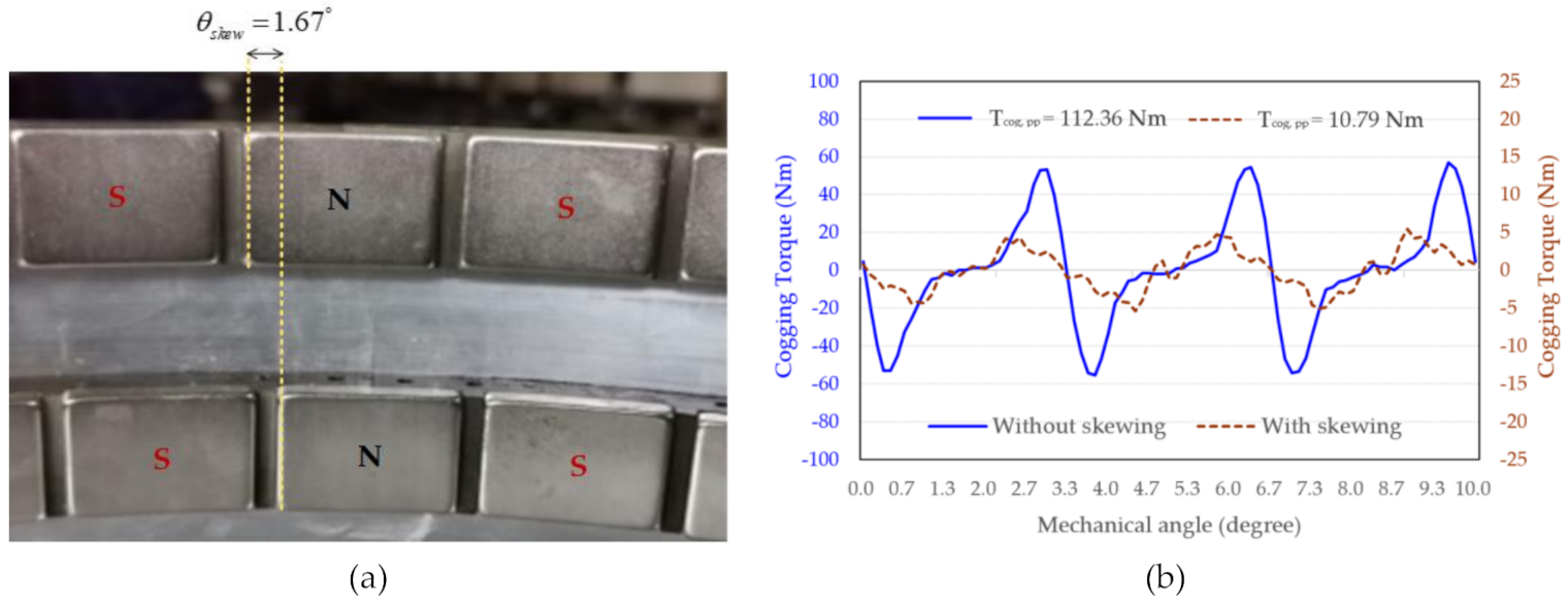
Figure 11 shows the windings for the wiring. The contacts are insulated and isolated by a heat-shrinkable tubing. The circuit uses six series and six parallel connections. In the industry, rotor skewing techniques are commonly used to weaken the harmonic electromotive force generated by the tooth magnetic field to reduce the cogging torque and minimize the torque ripple of the PSWG. If the cogging torque is too large for the application of the PSWG, it may not be able to activate and operate smoothly. Therefore, the reduction is an issue that needs to be addressed. According to Equation (10), the rotor skew angle is related to the period of cogging torque. One complete cycle of cogging torque covered a mechanical angle of 3.33° for the PSWG with the 36 poles/108 slots. Generally, if the cogging torque waveform is symmetrical, Equation (11) can be used to eliminate the cogging torque. In this study, the magnet and the rotor silicon steel sheet are both of 2-stage structure, which can avoid the manufacturing difficulties in skewing, the required skew angle of the rotor is 1.67°, as shown in Figure 12a. Upon the installation of the magnet, it is necessary to add an indentation in the rotor mechanism to facilitate the sticking of the magnet. After the rotor skewing of the optimized PSWG by 1.67°, the peak-to-peak value of the cogging torque is 10.79 Nm, as shown in Figure 12b. The simulation results show that skewing can effectively reduce the cogging torque.
: the period of cogging torque in mechanical angle;
: Number of poles; : Number of slots;
: Skew angle; : Number of segments structure
Table 5 shows the comparison of the electrical characteristics of the simulation results with and without skewing. The simulation conditions are simulated at a speed of 300 rpm. According to Figure 13, the average torque with and without skewing are 337.6 Nm and 350.64 Nm, respectively. Although there is a slight decrease in average torque, the cogging torque and torque ripple are reduced by 90.40% and 22.54% respectively, and the efficiency is improved by 9.06%.
4.2. Experimental and Simulated Analysis
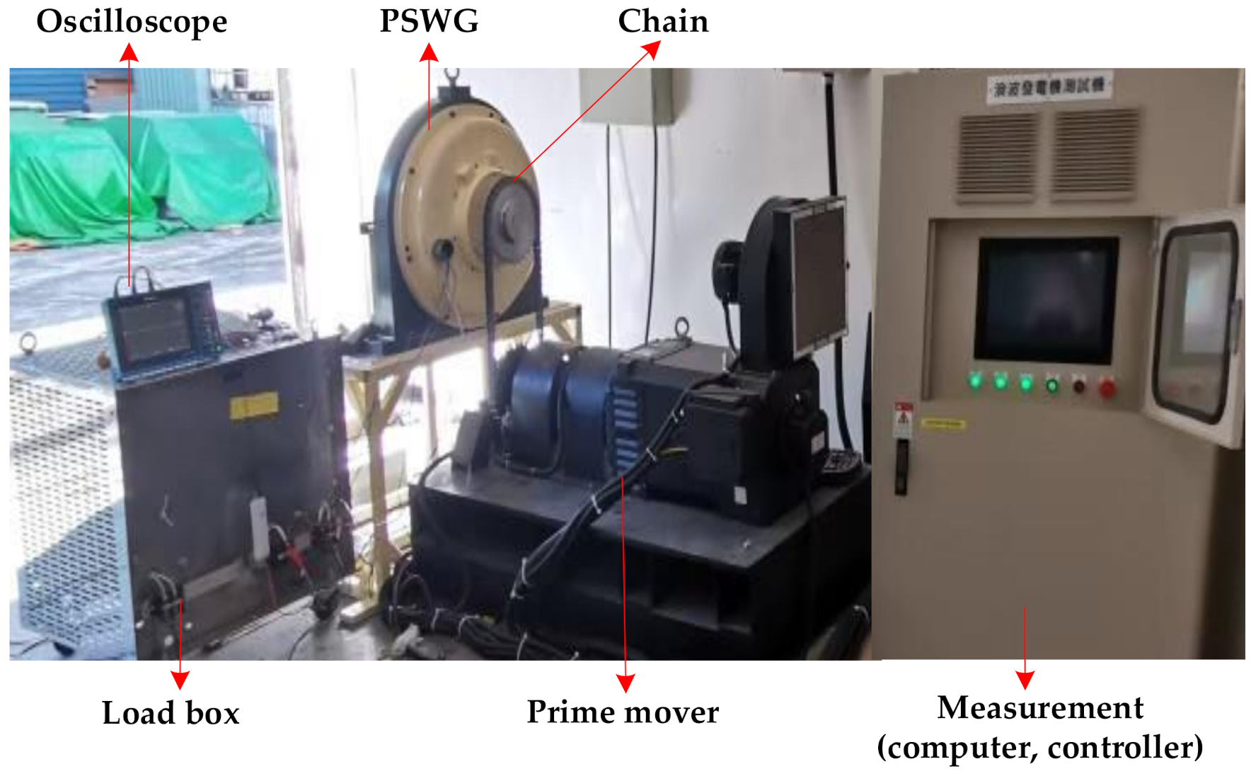
This section presents the experimental results for the proposed PSWG. The generator and its measurement platform are built and shown in Figure 14, which contains the prime mover control panel to adjust the prime mover’s driving speed. The 36-slot 108-pole PSWG under test is measured in the range of 100 to 300 rpm. The prime mover drives the chain to rotate the generator rotor. The generator circuit is connected to the load box and its characteristics are measured using an oscilloscope. A calculation of powers and efficiencies using simulated results was carried out for comparison to the experimental evaluation in this section.
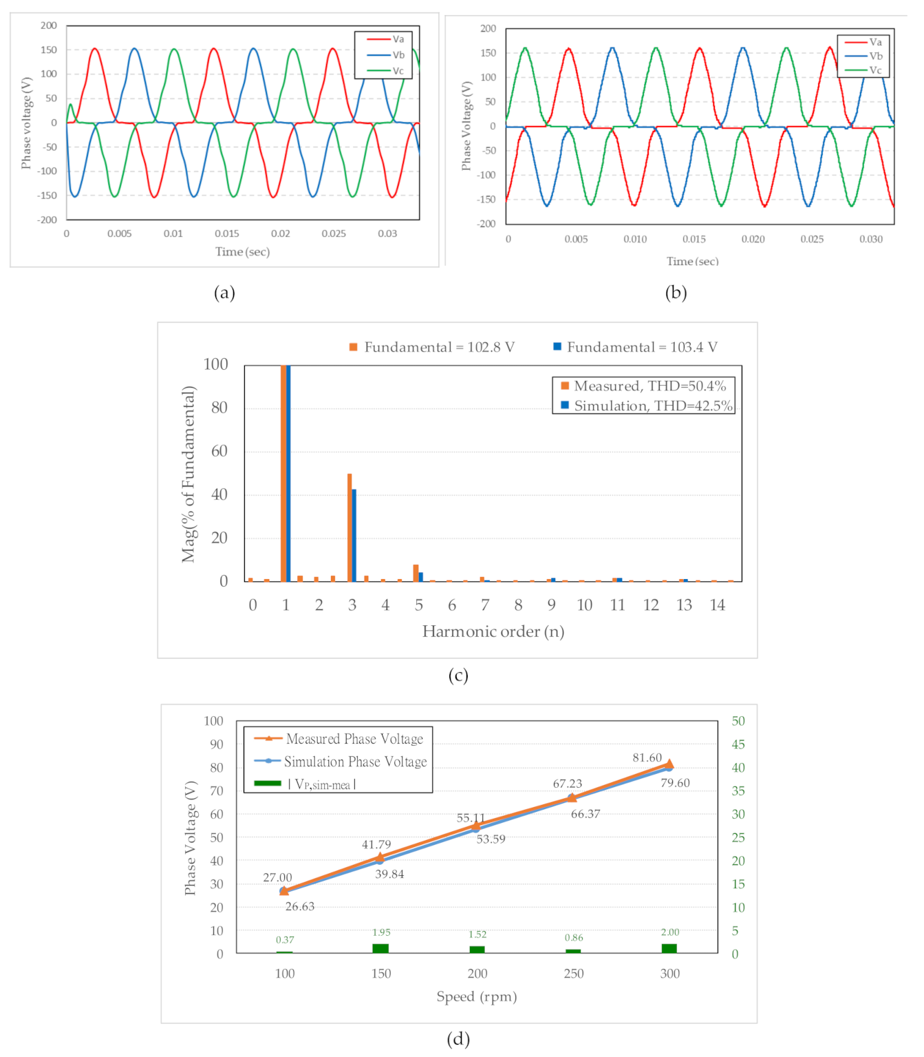
The measured and simulated phase voltages without load are shown in Figure 15a,b. As shown by the total harmonic distortion (THD) in Figure 15c, the frequency is mainly distributed at 90 Hz. The THD of the simulated and measured phase voltages without load are 42.5% and 50.4%, respectively. The power quality can be improved by changing the wiring method of the generator windings to achieve the effect of eliminating the third harmonic. After the seventh harmonic, the odd-order wave has a smaller influence and does not affect the fundamental wave shape. The root-mean-square error (RMSE) of the phase voltage is 1.48 V between the measured and simulated results, as shown in Figure 15d.
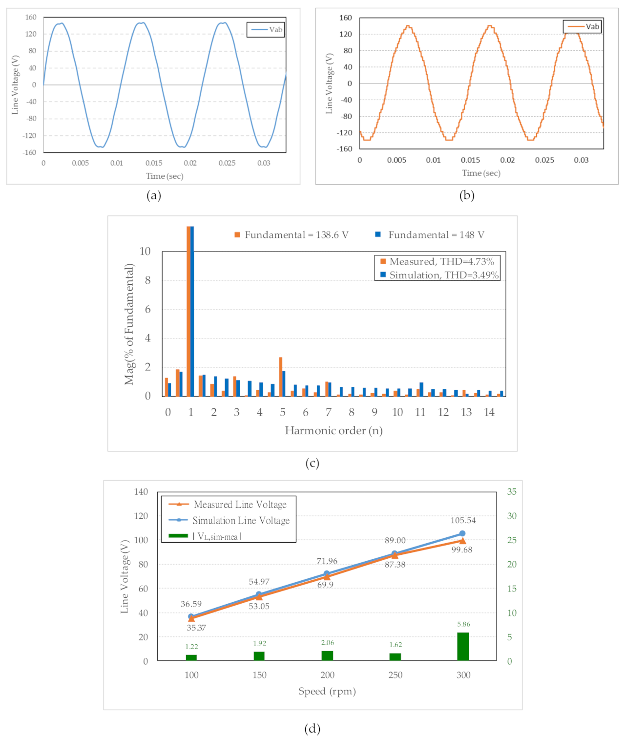
The simulated and experimental results of the line voltage waveforms at 3.6 Ω are shown in Figure 16. The corresponding waveforms of the line voltages in Figure 16a,b show near-sinusoidal outputs. According to Figure 16c, the THD of the simulated and measured results for the proposed PSWG are 3.49% and 4.73%, respectively. According to the National Standards of the Republic of China (CNS), the THD rate of the low-voltage system must be lower than 8%. The simulated and measured results meet the above standards. Figure 16d shows that the differences for the peak values of Va of the simulation and experimental results are 105.54 and 99.68 V at 300 rpm, respectively.
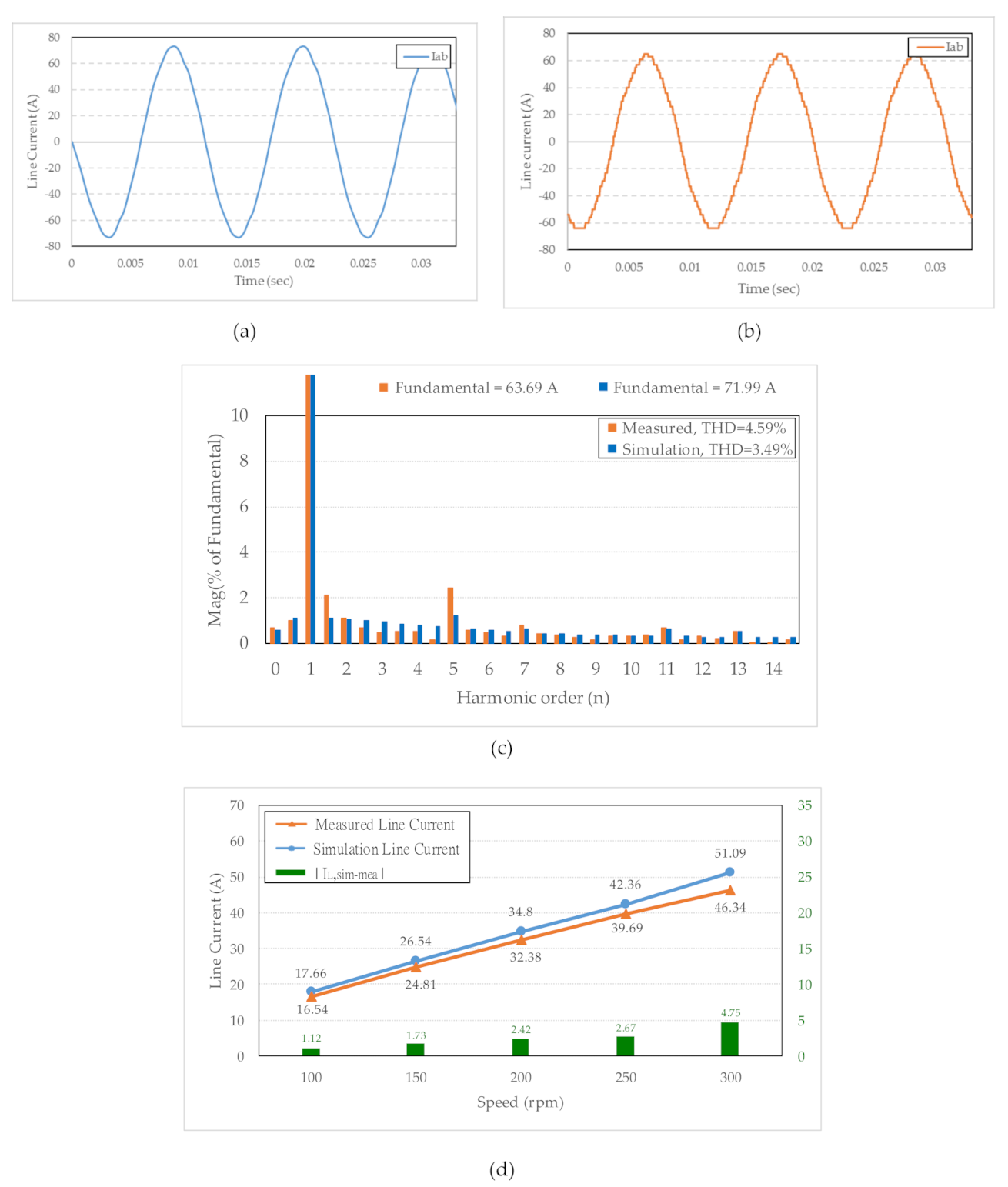
Figure 17a,b show the simulated and measured line currents at 3.6 Ω with 300 rpm, respectively. The fundamental analysis of the simulated line current is 71.99 A, while the fundamental analysis of the measured line current is 63.69 A, as shown in Figure 17c. Figure 17d demonstrates that the differences between the simulation and experimental results. The maximum difference of the line current is 4.75A at 300rpm, and the minimum one is 1.12A at 100rpm.
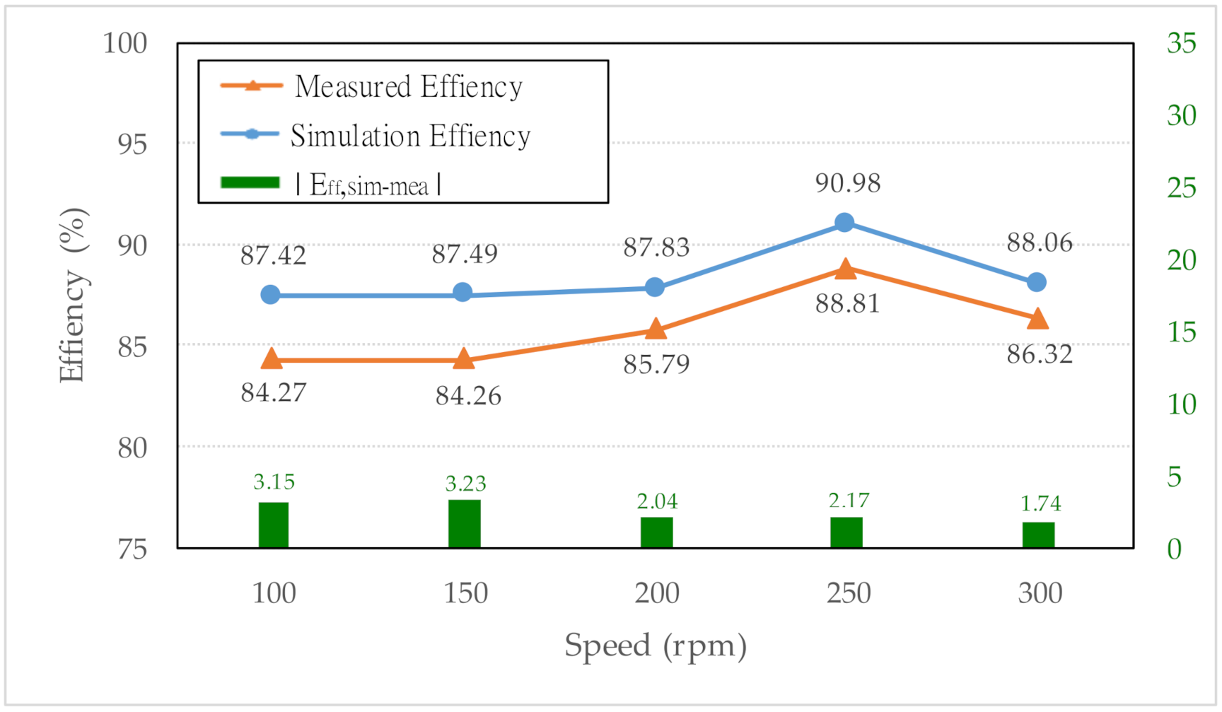
The efficiency of the PSWG can be calculated by Equation (12). The input mechanical power of the generator can be calculated by the torque and speed of rotation of the prime mover. The output mechanical power of the generator could be determined by the line voltage and line current of the generator at 3.6 Ω. The simulated and measured results are shown in Table 6, which indicates output powers of 9339.28 and 8000.64 W at 300 rpm, respectively. Figure 18 shows the simulation and relationship diagram of the efficiency corresponding to the actual measurement calibration. The average efficiency of the simulated and measured are 88.36% and 85.89%, respectively.
: output power; input power; : RMS load line voltage; : RMS load line current; : speed; : torque
5. Conclusions
This study presents a systematic and optimized analysis for the PSWG using the finite-element method, JMAG, and Taguchi method. The rotor skewing was implemented to effectively reduce the cogging torque. Furthermore, the proposed PSWG with an outer rotor was successfully designed and developed. The output power could be increased from 7619 W (prototype model) to 8001 W. According to the comparison of the experiment and simulation analyses, the root-mean-square error (RMSE) of the line voltage and line current at rotational speeds of 100 to 300 rpm at a load of 3.6 Ω per phase are 3.05 V and 2.82 A, respectively. These results show that the proposed method can guarantee the feasibility of the analysis and design of the high-performance PSWG.
Author Contributions
Conceptualization, C.-Y.H.; Formal analysis, C.-H.L.; Investigation, Z.-X.Z. and C.-Y.H.; Methodology, C.-H.L., Z.-X.Z., G.-Y.L. and C.-Y.H.; Writing—original draft, Z.-X.Z.; Writing—review and editing, C.-Y.H.; All authors have read and agreed to the published version of the manuscript.
Funding
This research was funded by Ministry of Science and Technology, Taiwan (MOST 109-2221-E-011-051-MY2, MOST 108-2637-E-011-002) and Industrial Technology Research Institute for their financial support.
Institutional Review Board Statement
Not applicable.
Informed Consent Statement
Not applicable.
Data Availability Statement
Data available on request.
Acknowledgments
Thanks to Japan 株式会社JSOL and Taiwan WisEnergy company provide software and technical support.
Conflicts of Interest
The authors declare no conflict of interest.
References
- Halamay, D.A.; Brekken, T.K.A.; Simmons, A.; McArthur, S. Reserve Requirement Impacts of Large-Scale Integration of Wind, Solar, and Ocean Wave Power Generation. IEEE Trans. Sustain. Energy 2011, 2, 321–328. [Google Scholar] [CrossRef]
- Jiang, L.; Chi, Y.; Qin, H.; Pei, Z.; Li, Q.; Liu, M.; Bai, J.; Wang, W.; Feng, S.; Kong, W.; et al. Wind Energy in China. IEEE Power Energy Mag. 2011, 9, 36–46. [Google Scholar] [CrossRef]
- Trainer, T. The limits to solar thermal electricity. Energy Policy 2014, 73, 57–64. [Google Scholar] [CrossRef]
- Vining, J.G.; Muetze, A. Economic factors and incentives for ocean wave energy conversion. IEEE Trans. Ind. Appl. 2009, 45, 547–554. [Google Scholar] [CrossRef]
- World Energy Council (WEC). Renewable Energy Resources: Opportunities and Constraints 1990–2020; Technical Report; World Energy Council: London, UK, 1993. [Google Scholar]
- Soukissian, T.H.; Denaxa, D.; Karathanasi, F.; Prospathopoulos, A.; Sarantakos, K.; Iona, A.; Georgantas, K.; Mavrakos, S. Marine Renewable Energy in the Mediterranean Sea: Status and Perspectives. Energies 2017, 10, 1512. [Google Scholar] [CrossRef] [Green Version]
- Williamson, B.J.; Blondel, P.; Armstrong, E.; Bell, P.S.; Hall, C.; Waggitt, J.J.; Scott, B.E. A Self-Contained Subsea Platform for Acoustic Monitoring of the Environment Around Marine Renewable Energy Devices–Field Deployments at Wave and Tidal Energy Sites in Orkney, Scotland. IEEE J. Ocean. Eng. 2016, 41, 67–81. [Google Scholar]
- Hamilton, R.J. DC motor brush life. IEEE Trans. Ind. Appl. 2000, 36, 1682–1687. [Google Scholar] [CrossRef]
- Ngu, S.S.; Dorrell, D.G.; Cossar, C. Design and operation of very slow speed generators for a Bristol cylinder sea wave generating device. IEEE Trans. Ind. Appl. 2014, 50, 2749–2759. [Google Scholar] [CrossRef]
- Polinder, H.; Damen, M.E.C.; Gardner, F. Linear PM generator system for wave energy conversion in the AWS. IEEE Trans. Energy Convers. 2004, 19, 583–589. [Google Scholar] [CrossRef] [Green Version]
- Liu, C.Y.; Yu, H.T.; Hu, M.Q.; Liu, Q.; Zhou, S.G. Detent force reduction in permanent magnet tubular linear generator for direct-driver wave energy conversion. IEEE Trans. Magn. 2013, 49, 1913–1916. [Google Scholar] [CrossRef]
- So, R.; Simmons, A.; Simmons, T.; Ruehl, K. Development of PTO-Sim: A power performance module for the open-source wave energy converter code WEC-Sim. In Proceedings of the ASME 2015 34th International Conference on Ocean, Offshore and Arctic Engineerin, St. John’s, NL, Canada, 31 May—5 June 2015; pp. 1–10. [Google Scholar]
- Fang, H.W.; Cheng, J.J.; Ren, Y.Q. Force analysis of float-type wave energy converter. J. Tianjin Univ. 2014, 47, 446–451. [Google Scholar]
- Jing, Z.; Yu, H.T.; Shi, Z.C. Design and Experiment Analysis of a Direct-Drive Wave Energy Converter with a Linear Generator. Energies 2018, 4, 735. [Google Scholar]
- Mendes, R.; Calado, M.D.R.; Mariano, S. Maximum Power Point Tracking for a Point Absorber Device with a Tubular Linear Switched Reluctance Generator. Energies 2018, 9, 2192. [Google Scholar] [CrossRef] [Green Version]
- Zhu, L.; Jiang, S.Z.; Zhu, Z.Q.; Chan, C.C. Analytical methods for minimizing cogging torque in permanent-magnet machines. IEEE Trans. Magn. 2009, 45, 2023–2031. [Google Scholar] [CrossRef]
- Bianchi, N.; Bolognani, S. Design techniques for reducing the cogging torque in surface-mounted pm motors. IEEE Trans. Ind. Appl. 2002, 38, 1259–1265. [Google Scholar] [CrossRef]
- Azar, Z.; Zhu, Z.Q.; Ombach, G. Influence of electric loading and magnetic saturation on cogging torque, back-emf and torque ripple of pm machines. IEEE Trans. Magn. 2012, 48, 2650–2658. [Google Scholar] [CrossRef]
- Jiang, J.W.; Bilgin, B.; Yang, Y.; Sathyan, A.; Dadkhah, H.; Emadi, A. Rotor skew pattern design and optimization for cogging torque reduction. IET Electr. Syst. Transp. 2016, 6, 126–135. [Google Scholar] [CrossRef]
- Washington, J.G.; Atkinson, G.J.; Baker, N.J. Reduction of cogging torque and emf harmonics in modulated pole machines. IEEE Trans. Energy Convers. 2016, 31, 759–768. [Google Scholar] [CrossRef]
- Phadke, M.S. Quality Engineering Using Robust Design; Prentice Hall: Hoboken, NJ, USA, 1995; pp. 61–232. [Google Scholar]
- Ross, P.J. Taguchi Techniques for Quality Engineering; McGraw-Hill Book Company: New York, NY, USA, 1995; pp. 103–107. [Google Scholar]
- Lee, H.H. Taguchi Methods: Principles and Practices of Quality Design; Gau Lih Book Company Ltd.: Taipei, Taiwan, 2011; pp. 95–326. [Google Scholar]
- Kim, K.C.; Lee, J.; Kim, H.J.; Koo, D.H. Multiobjective optimal design for interior permanent magnet synchronous motor. IEEE Trans. Magn. 2009, 45, 1780–1783. [Google Scholar]
- Kim, S.I.; Lee, J.Y.; Kim, Y.K.; Kim, Y.K.; Hong, J.P.; Hur, Y.; Jung, Y.H. Optimization for reduction of torque ripple in interior permanent magnet motor by using the Taguchi method. IEEE Trans. Magn. 2005, 41, 1796–1799. [Google Scholar]
- Hwang, C.C.; Lyu, L.Y.; Liu, C.T.; Li, P.L. Optimal design of an spm motor using genetic algorithms and Taguchi method. IEEE Trans. Magn. 2008, 44, 4325–4328. [Google Scholar] [CrossRef]
- Hwang, C.C.; Li, P.L.; Liu, C.T. Optimal design of a permanent magnet linear synchronous motor with low cogging force. IEEE Trans. Magn. 2012, 48, 1039–1042. [Google Scholar] [CrossRef]
- Cui, J.; Xiao, W.; Zou, W.; Liu, S.; Liu, Q. Design optimization of submersible permanent magnet synchronous motor by com-bined DOE and Taguchi approach. IET Electr. Power Appl. 2020, 14, 1060–1066. [Google Scholar] [CrossRef]
- Lim, D.K.; Jung, S.Y.; Yi, K.P.; Jung, H.K. A Novel Sequential-Stage Optimization Strategy for an Interior Permanent Magnet Synchronous Generator Design. IEEE Trans. Ind. Electron. 2018, 65, 1781–1790. [Google Scholar] [CrossRef]
- Reza, N.Z.; Akbar, M.A.; Karim, A. Design Optimization of a Transverse Flux Halbach-Array PM Generator for Direct Drive Wind Turbines. IEEE Trans. Energy Convers. 2020, 35, 1485–1493. [Google Scholar]
- Hanselman, D. Brushless Permanent Magnet Motor Design; Manga Physics Pub.: Orono, ME, USA, 2003. [Google Scholar]
Figure 1.
Wave Generator: (a) Floating-point absorber; (b) Geometric structure of a 36-pole/108-slot PSWG.
Figure 1.
Wave Generator: (a) Floating-point absorber; (b) Geometric structure of a 36-pole/108-slot PSWG.

Figure 2.
Winding diagram of 36 poles/108 slots Y connection when (a), (b), and (c) represense three-phase structure.
Figure 2.
Winding diagram of 36 poles/108 slots Y connection when (a), (b), and (c) represense three-phase structure.

Figure 3.
Schematic flux path diagram of general surface permanent-magnet synchronous generator.

Figure 4.
Magnetic circuit of general structure: (a) complete magnetic circuit; (b) simplified magnetic circuit.
Figure 4.
Magnetic circuit of general structure: (a) complete magnetic circuit; (b) simplified magnetic circuit.

Figure 5.
Relationship between normalized air-gap flux density and permeability.

Figure 6.
Magnetic field of PSWG: (a) distribution of flux line; (b) map of flux density distribution.
Figure 6.
Magnetic field of PSWG: (a) distribution of flux line; (b) map of flux density distribution.

Figure 7.
Relationship between normalized air-gap flux density and permeability.

Figure 8.
Configuration with control factor.

Figure 9.
Factor response chart.

Figure 10.
Magnetic field at 300 rpm: (a) distribution of flux line; (b) map of flux density distribution.
Figure 10.
Magnetic field at 300 rpm: (a) distribution of flux line; (b) map of flux density distribution.

Figure 11.
(a,b) Generator stator winding.

Figure 12.
The rotor skewing technique: (a) step skew of rotor magnetic poles; (b) cogging torque comparison.
Figure 12.
The rotor skewing technique: (a) step skew of rotor magnetic poles; (b) cogging torque comparison.

Figure 13.
Torque at speed 300 rpm.

Figure 14.
Experimental apparatus.

Figure 15.
No-load phase voltage: (a) Simulated with 300 rpm; (b) Measured with 300 rpm; (c) Harmonic analysis be-tween simulated and measured; (d) Comparison of simulated and measured no-load phase voltage (RMS).
Figure 15.
No-load phase voltage: (a) Simulated with 300 rpm; (b) Measured with 300 rpm; (c) Harmonic analysis be-tween simulated and measured; (d) Comparison of simulated and measured no-load phase voltage (RMS).

Figure 16.
Line voltage with 3.6 Ω load: (a) Simulation with 300 rpm; (b) Measured with 300 rpm; (c) Harmonic analy-sis between simulated and measured; (d) Comparison of simulated and measured load line voltage (RMS).
Figure 16.
Line voltage with 3.6 Ω load: (a) Simulation with 300 rpm; (b) Measured with 300 rpm; (c) Harmonic analy-sis between simulated and measured; (d) Comparison of simulated and measured load line voltage (RMS).

Figure 17.
Line current with 3.6 Ω load: (a) Simulation with 300 rpm; (b) Measured with 300 rpm; (c) Harmonic analy-sis between simulated and measured; (d) Comparison of simulation and measured load line current (RMS).
Figure 17.
Line current with 3.6 Ω load: (a) Simulation with 300 rpm; (b) Measured with 300 rpm; (c) Harmonic analy-sis between simulated and measured; (d) Comparison of simulation and measured load line current (RMS).

Figure 18.
Comparison of simulated and measured efficiency curve.


Table 1.
Specifications of outer rotor generator.
| Structural Parameters (Unit) | Value |
|---|---|
| Number of slots | 108 |
| Number of poles | 36 |
| Stator inner diameter (mm) | 318 |
| Stator outer diameter (mm) | 435 |
| Rotor outer diameter (mm) | 470 |
| Rotor inner diameter (mm) | 438 |
| Product thickness (mm) | 55 |
| Air gap length (mm) | 1.5 |
| Coil turns | 44 |
| Stator material | 50CS470 |
| Magnet material | N35 |
| Magnet thickness (mm) | 6 |
Table 2.
Control factors and levels.
| Factor | Items | Level 1 | Level 2 | Level 3 | Level 4 | ||
|---|---|---|---|---|---|---|---|
| A | d1 | Shoes outer length | (mm) | 1.2 | 1.6 | 2.0 | 2.4 |
| B | lso | Slot opening width | (mm) | 1.8 | 3.0 | 4.3 | 5.5 |
| C | wcurve | Pole–pitch ratio | 0.6 | 0.7 | 0.8 | 0.9 | |
| D | larc | Pole–arc ratio | (%) | 0 | 30 | 60 | 90 |
| E | lm | Magnet thickness | (mm) | 4.5 | 5.0 | 5.5 | 6.0 |
Table 3.
L16 array.
| A (mm) | B (mm) | C | D (%) | E (mm) | Output Power (W) | S/N Ratio | |
|---|---|---|---|---|---|---|---|
| 1 | 1.2 | 1.8 | 0.6 | 0 | 4.5 | 6273 | 75.95 |
| 2 | 1.2 | 3.0 | 0.7 | 30 | 5.0 | 7213 | 77.16 |
| 3 | 1.2 | 4.3 | 0.8 | 60 | 5.5 | 7740 | 77.78 |
| 4 | 1.2 | 5.5 | 0.9 | 90 | 6.0 | 7827 | 77.87 |
| 5 | 1.6 | 1.8 | 0.7 | 60 | 6.0 | 7561 | 77.57 |
| 6 | 1.6 | 3.0 | 0.6 | 90 | 5.5 | 6185 | 75.83 |
| 7 | 1.6 | 4.3 | 0.9 | 0 | 5.0 | 7709 | 77.74 |
| 8 | 1.6 | 5.5 | 0.8 | 30 | 4.5 | 6931 | 76.82 |
| 9 | 2.0 | 1.8 | 0.8 | 90 | 5.0 | 7518 | 77.52 |
| 10 | 2.0 | 3.0 | 0.9 | 60 | 4.5 | 7524 | 77.53 |
| 11 | 2.0 | 4.3 | 0.6 | 30 | 6.0 | 6736 | 76.57 |
| 12 | 2.0 | 5.5 | 0.7 | 0 | 5.5 | 7104 | 77.03 |
| 13 | 2.4 | 1.8 | 0.9 | 30 | 5.5 | 7982 | 78.04 |
| 14 | 2.4 | 3.0 | 0.8 | 0 | 6.0 | 8126 | 78.20 |
| 15 | 2.4 | 4.3 | 0.7 | 90 | 4.5 | 6470 | 76.22 |
| 16 | 2.4 | 5.5 | 0.6 | 60 | 5.0 | 5761 | 75.21 |
Table 4.
Factor response table.
| Factor | A | B | C | D | E |
|---|---|---|---|---|---|
| Level 1 | 77.19 | 77.27 | 75.89 | 77.23 | 76.63 |
| Level 2 | 76.99 | 77.18 | 77.00 | 77.15 | 76.91 |
| Level 3 | 77.16 | 77.08 | 77.58 | 77.02 | 77.17 |
| Level 4 | 76.92 | 76.73 | 77.80 | 76.86 | 77.55 |
| Level,max–Level,min | 0.27 | 0.54 | 1.91 | 0.37 | 0.92 |
| Rank | 5 | 3 | 1 | 4 | 2 |
Table 5.
Comparison of electrical characteristics with and without skewing.
| Characteristics | Without Skewing | With Skewing | Difference (%) | |
|---|---|---|---|---|
| Rated Speed | (rpm) | 300 | 300 | - |
| Cogging Torque | (N-m) | 112.36 | 10.79 | −90.40 |
| Torque | (N-m) | 350.64 | 337.6 | −5.59 |
| Torque ripple | (%) | 28.26 | 5.72 | −22.54 |
| Output Power | (W) | 8675.84 | 9339.28 | +7.65 |
| Efficiency | (%) | 79.00 | 88.06 | +9.06 |
| Rotor material | 50CS470 | 50CS470 | - | |
| Stator material | 50CS470 | 50CS470 | - | |
| Permanent magnet | N35 | N35 | - | |
| Rotor steel weight | (kg) | 6.12 | 6.12 | 0 |
| Stator steel weight | (kg) | 21.61 | 18.92 | −12.45 |
| PM weight | (kg) | 2.72 | 3.12 | +14.71 |
| Copper weight | (kg) | 4.921 | 4.921 | 0 |
Table 6.
Comparison of simulated and measured efficiency with PSWG.
| Simulated Result | ||||
| Speed (rpm) | Input Torque (N-m) | Pin (W) | Pout (W) | Efficiency (%) |
| 100 | 122.26 | 1280.30 | 1119.22 | 87.42 |
| 150 | 183.87 | 2888.22 | 2526.90 | 87.49 |
| 200 | 235.80 | 4938.58 | 4337.42 | 87.83 |
| 250 | 274.15 | 7177.23 | 6529.90 | 90.98 |
| 300 | 337.60 | 11862.65 | 9339.28 | 88.06 |
| Measured Result | ||||
| Speed (rpm) | Input Torque (N-m) | Pin (W) | Pout (W) | Efficiency (%) |
| 100 | 114.82 | 1202.39 | 1013.28 | 84.27 |
| 150 | 172.23 | 2705.38 | 2279.67 | 84.26 |
| 200 | 218.19 | 4569.76 | 3920.26 | 85.79 |
| 250 | 258.35 | 6763.59 | 6006.95 | 88.81 |
| 300 | 295.02 | 9268.33 | 8000.64 | 86.32 |
Publisher’s Note: MDPI stays neutral with regard to jurisdictional claims in published maps and institutional affiliations. |
© 2021 by the authors. Licensee MDPI, Basel, Switzerland. This article is an open access article distributed under the terms and conditions of the Creative Commons Attribution (CC BY) license (https://creativecommons.org/licenses/by/4.0/).
Share and Cite
MDPI and ACS Style
Hsiao, C.-Y.; Lai, C.-H.; Zheng, Z.-X.; Li, G.-Y. Design and Implement of Three-Phase Permanent-Magnet Synchronous Wave Generator using Taguchi Approach. Energies 2021, 14, 2010. https://0-doi-org.brum.beds.ac.uk/10.3390/en14072010
AMA Style
Hsiao C-Y, Lai C-H, Zheng Z-X, Li G-Y. Design and Implement of Three-Phase Permanent-Magnet Synchronous Wave Generator using Taguchi Approach. Energies. 2021; 14(7):2010. https://0-doi-org.brum.beds.ac.uk/10.3390/en14072010
Chicago/Turabian StyleHsiao, Chun-Yu, Chin-Hsiang Lai, Zhu-Xuan Zheng, and Guan-Yu Li. 2021. "Design and Implement of Three-Phase Permanent-Magnet Synchronous Wave Generator using Taguchi Approach" Energies 14, no. 7: 2010. https://0-doi-org.brum.beds.ac.uk/10.3390/en14072010
Note that from the first issue of 2016, this journal uses article numbers instead of page numbers. See further details here.