
Application and Design Aspects of Ground Heat Exchangers


Faculty of Mechanical Engineering and Naval Architecture, University of Zagreb, Ivana Lucica 5, 10000 Zagreb, Croatia
*
Author to whom correspondence should be addressed.
Energies 2021, 14(8), 2134; https://0-doi-org.brum.beds.ac.uk/10.3390/en14082134
Submission received: 2 March 2021
/
Revised: 23 March 2021
/
Accepted: 6 April 2021
/
Published: 11 April 2021
(This article belongs to the Special Issue Heat Exchangers: Cooling and Heating Systems)
Abstract
:With the constant increase in energy demand, using renewable energy has become a priority. Geothermal energy is a widely available, constant source of renewable energy that has shown great potential as an alternative source of energy in achieving global energy sustainability and environment protection. When exploiting geothermal energy, whether is for heating or cooling buildings or generating electricity, a ground heat exchanger (GHE) is the most important component, whose performance can be easily improved by following the latest design aspects. This article focuses on the application of different types of GHEs with attention directed to deep vertical borehole heat exchangers and direct expansion systems, which were not dealt with in detail in recent reviews. The article gives a review of the most recent advances in design aspects of GHE, namely pipe arrangement, materials, and working fluids. The influence of the main design parameters on the performance of horizontal, vertical, and shallow GHEs is discussed together with commonly used performance indicators for the evaluation of GHE. A survey of the available literature shows that thermal performance is mostly a point of interest, while hydraulic and/or economic performance is often not addressed, potentially resulting in non-optimal GHE design.
1. Introduction
Geothermal energy is a renewable form of energy that can be used for electricity production or can be utilized for heating and cooling applications [1]. The latter is commonly described as low temperature, shallow geothermal energy use where ground resources up to approximately 400 m below the surface are used. To do so, different types of ground heat exchangers (GHEs) are buried underground to exchange heat with the surrounding soil. Based on installation depth, systems are commonly divided into horizontal systems that are installed just below the surface in excavated trenches and vertical systems where boreholes are drilled to larger depths and grouted. In between, a group of shallow systems up to the depth of 30 m in form of energy piles or large diameter helical coils exist. Geothermal systems can also be classified as open or closed systems [2]. In an open system configuration, air or water from the surrounding flows through a heat exchanger, exchanging heat with the underground, and is then used in heating, cooling, or ventilation systems. In a closed configuration, secondary working fluid circulates in a heat exchanger in the closed-loop and exchanges heat with the underground; therefore, only heat transfer is accounted for.
Ground coupled system efficiency is based on the stable underground temperature that results from the combined effect of the ground thermal inertia that dampens the temperature changes on the surface and continuous geothermal gradient [3]. Depending on the depth, the underground temperature is higher in winter and lower in summer compared to the outside air. Direct use of shallow geothermal energy is possible in the ground-to-earth heat exchangers for partial or complete conditioning of inlet air used for ventilation. The temperature level of the shallow underground usually is not enough to fully cover cooling and heating needs, so ground heat exchangers are coupled to heat pumps (GSHP) [1,4]. Heat pump performance is strongly dependent on a heat sink and source temperatures; therefore, it is imperative that the ground heat exchanger is designed efficiently and cost-effectively, as installation costs increase with installation depth [5,6].
2. Literature Review
When the thermal performance of GHE is considered, the largest influence is attributed to the underground thermal properties, as shown by different sensitivity analyses found in the literature [7,8]. Authors also stress that relative differences in performance diminish with the increase of ground thermal properties. Determination of local geological properties can facilitate GHE performance. Numerical simulation of the EAHE (earth- to-air heat exchanger) in different geotechnical profiles showed high relative improvements (around 60%) if the EAHE duct was installed in a higher conductive layer, even if better performing soil was closer to the surface [9]. The use of dedicated backfill or coating material also proves beneficial. Cuny et al. [10] developed a numerical heterogonous ground model to evaluate the effect of the coating or backfill soil and soil moisture on the thermal performance of EAHE. Improvement of 15.9% for the same soil with different moisture content and 17.4% with different coating soils in a low humidity case demonstrated that coating soil for the EAHE has a noticeable effect. A similar conclusion is made in the numerical investigation of the horizontal ground heat exchanger (HGHE), where the height of coating soil and moisture content can improve specific heat rate up to 50% [11]. Use of backfill soil with moisture retention capacity is suggested, as water impregnation can facilitate mitigation of soil thermal saturation [12]. The experimental analysis showed an increase of average heat transfer rate in moist soil between 22.7% and 24.1% during cooling and between 15.6% and 22.8% during heating operation, depending on moisture content (5–20%) [13]. Instantaneous change of soil moisture due to rainfall is experimentally and numerically investigated by Cuny et al. [14]. A laboratory-scale experimental setup was used to simulate different rainfalls with varying intensity and time duration and their effect on moisture content. Developed vertical profiles of moisture content were used for numerical modeling of EAHE in moist soil. The numerical results showed an energy enhancement from rainfall events: energy performance increases by 4% during the first 24 h after the beginning of the rainfall and about 2% after a further 24 h. Investigation of GHE operating under transient conditions conducted by several authors showed benefits of the cyclic operation and use of metal pipe materials with higher thermal conductivity [15,16]. Surface conditions differently affect GHE systems. The performance of an open-type horizontal system like EAHE is highly affected by ambient temperature, as shown by the transient semi-analytical model of Rouag et al. [17]. Still, in the HGHE system, the annual variation of surface temperature, damped by installation depth, has a small influence on heat exchange compared to the piping layout [18]. If a multi-pipe configuration is considered, the connection layout of the main distribution pipe and section parallel pipes affects working medium distribution and pressure drop. U-type or L-type connection is preferred over Z-type due to a smaller pressure drop (up to 36% difference), more uniform airflow distribution (up to 80% higher uniformity), and an increased heat transfer rate (up to 5.8%) [19,20]. In the case of a multilayered configuration, the staggered arrangement of pipes increases the heat rate compared to a parallel arrangement. For the ratio of the horizontal offset to the value of the distance between the upper and lower layer of pipes equal to 1, the heat transfer rate is improved by 47% compared to the parallel pipe layout [18].
The influence of the surface conditions diminishes with depth, as can be seen from the numerical model that takes into account seasonal air temperature variations [21]. The analytical finite line source model developed by Rivera et al. showed that different boundary conditions exhibit differences smaller than 5% for sufficiently long BHE (larger than 50 m) [22]. The influence of heterogeneity in ground layers is also reduced when a heat pump coupled to the vertical borehole heat exchanger is considered [23]. Two usual designs of vertical GHE are coaxial BHE and U-tube BHE. Semi-analytical modeling of coaxial BHE is improved by Gordon et al. [24]. With an improved model, a variation of pipe material is investigated (an insulated inner pipe, steel outer pipe) and compared to standard HDPE as the baseline case. A steel outer pipe was concluded to have a greater impact on reducing the depth of BHE. Similar conclusions were obtained by Oh et al. [25] based on experimental studies of the heat exchange performance of various coaxial-type GHE. Four different 50-m deep coaxial GHE were constructed in a testbed with different grouting material, pipe diameter, and material. It was concluded that thermal performance is improved by increasing pipe diameter and thermal conductivity of pipe and grouting material, but improvements are not linear, so they should be optimized based on construction cost. Performance analysis of U-tube BHE was done by Kerme and Fung [26] with the help of an unsteady heat transfer simulation. To further avoid climate and environmental impact on the performance of GHE and to increase heat extraction, drilling a deeper borehole represents a good solution, as shown by Deng et al. [27]. To assess the potential use of DBHE and to further improve this promising new technology, numerical simulations are mostly used to investigate the heat transfer process. Because of a geothermal gradient, numerical and analytical models for shallower BHE cannot be used. Numerical simulations are often time-consuming, so Fang et al. [28] developed a model and numerical algorithm for analyzing DBHE that is both efficient and accurate. Numerical models of heat transfer in DBHE were also made by Song et al. [29] (unsteady-state) and Liu et al. [30] (model with logarithmic discretization in a radial direction). The CFD model for DBHE close to magma intrusion was made by Renaud et al. [31]. To enable faster design and calculation of DBHE, analytical models were necessary. As mentioned, the geothermal gradient is significant, so the models for BHE do not apply to DBHE. Analytical heat transfer models for coaxial DBHE were presented by Pan et al. [32] and Luo et al. [33]. These models had simplified heat transfer, so further improvement in analytical modeling of heat transfer in DBHE was made by Luo et al. [34] with their model based on a segmented finite cylinder-source model. Another important consideration in modeling DBHE is presented by Hu et al. [35]. They analyzed the effects of temperature-dependent properties on the prediction of output capacity of DBHE under operational conditions. Properties included in the numerical simulation were specific heat, the thermal conductivity of water and reservoir rocks, and the density and dynamic viscosity of the fluid. They concluded that output capacity can be overpredicted up to 9%.
The direct expansion ground-coupled system (DX-GSHP) uses similar geometry of heat exchangers inserted in the ground while working fluid inside GHE is refrigerant. In this case, the GHE is an integral part of the heat pump, and research interest is broader than only design aspects, as the phase change process of refrigerant in GHE affects all components of the heat pump cycle. Bastani et al. [36] presented the experimental results of CO2 DX-GSHP for different heating applications: domestic hot water (50–65 °C), heating coil space heating (37–50 °C), and radiant floor space heating (25–37 °C). The GHE consisted of four 30 m vertical boreholes with single copper U pipe. Proper system control has been proven to be crucial, as it leads to optimal discharge pressure, which maximizes the COP of the system. A numerical model of variable speed transcritical CO2 DX-GSHP used for conditioning of a small residential building was developed by Nguyen et al. [37]. The authors concluded that low compressor speed results in noticeable thermal short-circuiting between the two legs of the BHE and that the system has difficulties in maintaining 5 °C superheat; thus, the inclusion of an internal heat exchanger is suggested. Fannou et al. [38] conducted an experimental analysis of DX-GSHP in cooling mode. A ground heat exchanger with three parallel loops was inserted 30 m into the ground. One BHE was placed vertically, and two BHEs were inclined about 30°. The system achieved a maximum of 12 h continuous operation with COP in the range of 2.60 to 3.40 and an average ground heat rejection rate of about 290 W m−1. Horizontal ground heat exchangers with CO2 DX-GSHP were numerically investigated by Ghazizade-Ahsaee et al. [39]. The studied configurations included an expansion valve, expander, and intermediate heat exchanger with a peak heating capacity of 8 kW. The results of the exergy-economic analysis showed expected higher exergy efficiency using the expander compared to the electronic expansion valve. On the other hand, the cost per unit of heat followed the opposite trend. The slinky type of borehole heat exchanger in a horizontal and vertical configuration with DX-GSHP was experimentally studied in cooling mode by Soni et al. [40]. When compared to the conventional air conditioning systems, the DX system exhibited larger EER values in the range of 8% to 12%.
The following paragraph gives a short overview of recently published review papers. An overview of different GHE system layouts and integration with various cooling and heating technologies for zero-energy buildings is given by Gao et al. [41]. Hybrid systems using multiple renewable energy sources employed for heating and cooling application are analyzed by Soni et al. [42]. Comparative analysis of various geometrical aspects of GHEs, geothermal investigation, and materials is summarized by Aresti et al. [43]. Kaushal [44] reviewed different algorithms and analytical models used for the analysis and sizing of the earth-to-air heat exchangers (EAHE). The author also briefly addressed important design parameters like pipe material, diameter, length, thermal interference, etc. A review paper made by Singh et al. [45] discussed the effects of surface treatment on EAHE thermal performance among other design parameters and provided an overview of practical installations and the innovative design of systems. The effects of geographical and climatic conditions, operation parameters, and account of latent heat exchange were covered by Agrawal et al. [46]. The same authors also reviewed EAHE integration in hybrid systems with different renewable sources and recent research trends [47]. Different analytical, numerical, and economical models used to evaluate the performance of horizontal GHE configurations are presented by Cui et al. [48]; the authors concluded that advanced economical models that are rarely used would be beneficial to fully assess the time value of money and inflation rates. Influential parameters of the thermal performance of energy piles, design steps, and techno-mechanical behavior are addressed in work made by Sani et al. [49]. Faizal et al. reviewed heat transfer improving methods and geometrical optimization of energy piles [50]. A review of energy pile configurations, analytical and numerical models and sizing methods of energy piles were made by Fadejev et al. [51]. The authors also pointed out that energy piles are frequently misinterpreted as vertical boreholes, although significant differences between the geometry of energy piles and boreholes exist. Among GHE configurations, vertical borehole heat exchangers are the most extensively investigated. Noorollahi et al. [52] compiled investigations dealing with ground heat exchanger parameters’ influence on GSHP and GHE efficiency for horizontal and vertical systems, with more emphasis given to the latter. Cui et al. [53] reviewed analytical and numerical models used to investigate the thermal performance of different vertical configurations. Advances in GHE design are addressed in the review conducted by Javadi et al. [54]. Although different designs proposed in the literature improved heat transfer rate, most systems still employ U pipe geometry with PE pipes and water as a working fluid. Available commercial sizing tools are compared by Ahmadfard and Bernier [55], and results show that most of available tools predict a similar needed length of vertical BHEs despite different complexities of used models. Regulation of shallow geothermal systems in six different European countries with suggestions for improvement of the legislative framework to support the sustainable use of shallow geothermal systems is presented by Somogy et al. [56]. The development of a common European regulative framework is also suggested, based on a review of the legal status of shallow geothermal energy in selected European countries, by Tsagarakis et al. [57].
A large number of studies investigating the GHE were published, including review papers dealing with different aspects of shallow geothermal energy use. Application, investigation, and sizing of GHE systems vary from country to country depending on the local climatic data, development status, and legal framework. Similar influential design parameters, materials, and working fluids are used in different applications; still, not all affect the performance of different types of GHE systems in the same manner.
This review builds upon already published review articles and focuses on published studies in the last five years with the inclusion of applications that were not dealt with in detail, e.g., direct expansion and deep BHE systems. An important aspect of GHE research studies that is not properly addressed in the published literature is the criteria used for comparison and performance evaluation of different designs of GHEs. Based on the reviewed numerical and experimental studies, this paper is divided into three sections: application of ground heat exchangers, performance indicators for the evaluation of GHE performance, and design aspects of ground heat exchangers.
3. Application of Ground Heat Exchangers
3.1. Horizontal Heat Exchanger Configurations
Horizontal configurations include the direct use of ground thermal energy in the air to ground heat exchangers and horizontal ground heat exchangers coupled to the heat pump system. Both types of systems are installed in surface soil layers, where performance is affected by seasonal variations of soil temperature and moisture content. Local geological conditions, mainly ground thermal conductivity and heat capacity, affect the heat transfer in the underground.
Earth-to-air heat exchangers are the simplest configuration of heat exchangers when the use of renewable underground energy is considered. Commonly, they are abbreviated as EAHE [17,58], GAHE [59], or HAGHE [60,61], where the additional H letter designates horizontal installation. In an open system configuration, ambient air passes through the pipes inserted in the ground and exchanges heat with the ground [2]. Depending on the season, the air is heated or cooled before being distributed through the ventilation system or used as a heat source for an air source heat pump [62] (Figure 1). EAHE can also be employed as part of the thermally activated building systems (TABSs), where walls are constructed as hollow prefabricated building components or pipes are embedded inside walls [63]. In such systems, a closed-loop configuration can be used [41].
Horizontal ground heat exchangers (HGHE) are used as a closed system and are coupled to the heat pump. The ground exchanges thermal energy with the working fluid inside pipes. Being installed in 1–2 m deep trenches, their performance is comparatively lower than the vertical GSHP systems. The needed installation area for the horizontal system is larger, but installation costs are smaller compared to the vertical heat exchangers [2]. Based on pipe loop geometry, horizontal systems can be divided into linear-loop, spiral-coil, and slinky-coil configurations [11,48], and based on loop connections system can be further divided into a trench, series, and parallel configurations [48] (Figure 2). Compared to linear configurations, coil configurations enable more efficient use of the available ground while requiring longer pipes and increased pump work [64].
3.2. Vertical Heat Exchanger Configurations
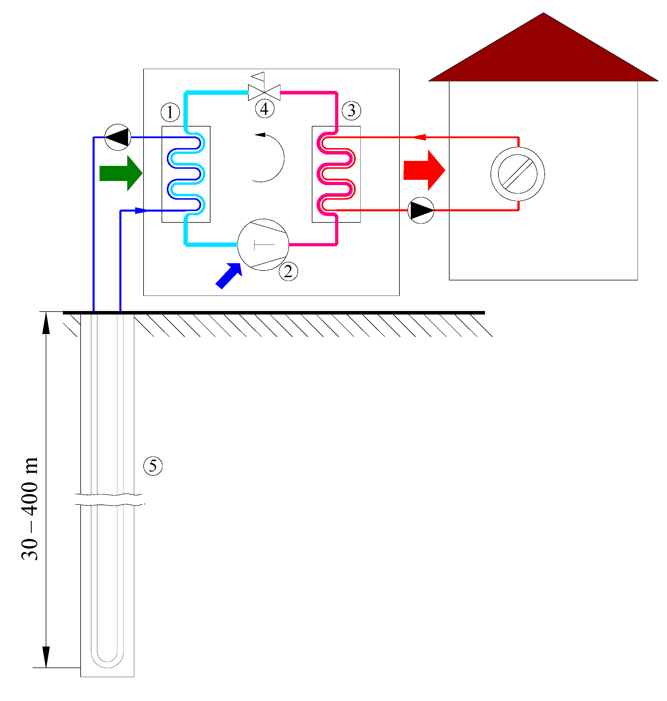
When sufficient ground area is available, as mentioned, horizontal GHEs present the most cost-effective option. However, if the available area is limited, the ground surface is rocky, and visual interference with the landscape is not welcome, vertical GHEs are applied. Vertical ground heat exchangers (VGHE) are also referred to as borehole heat exchangers (BHEs). In comparison with horizontal GHEs, BHEs have higher installation costs and more stable performance, as they are not affected severely by ambient air [65]. Vertical GHEs are divided into two groups depending on the depth of the borehole and, consequently, the type of heat exchanger. The first group, shallow boreholes GHE (<400 m), are usually used in combination with heat pumps (ground-coupled heat pumps—GCHP) as a source or sink for thermal energy (Figure 3). A traditional configuration consists of the borehole with a diameter usually around 100–200 mm containing U-tubes with a diameter in the range of 19–38 mm for working fluid to circulate [65]. Besides the most common single U-tube configuration, other configurations that can be used are double or triple U-tube, W-shaped tube, coaxial tube, and helical-shaped tube [53]. The annulus section of the borehole is made from various backfill materials referred to as grout, which reduces the thermal resistance between the pipes and ground and ensures good contact between materials. As the heat transfer area of such systems is limited, consequently, the thermal capacity (thermal power) of such systems is also limited. To achieve a higher thermal capacity of such systems, there are two possible solutions—increasing the number of boreholes (most of today’s installations) or increasing the depth of the borehole [66]. Increasing the number of boreholes is only available when there is sufficient available space.
The second option, to increase the thermal capacity of GHE, uses the technology of the deep borehole heat exchangers (DBHE), which can be also classified as the second category of vertical BHE. DBHE can extract medium-deep geothermal energy at high temperatures [67]. Although the literature does not give, to our knowledge, strict classification of BHEs by depth, a good definition is proposed by Sapinska-Sliwa et al. [67]. They proposed that deep borehole heat exchangers (DBHE) are those where there is a possibility that the extracted heat can be used directly (without the aid of HP). When using the technology of DBHE, classical U-tubes configurations are usually replaced with coaxial (pipe in a pipe) borehole heat exchangers, which have a larger heat transfer area and can sustain a larger flow rate (lower pumping costs) [68]. As over 50% of the total cost of the geothermal project can be drilling costs [69], a good solution to reduce high drilling costs is presented by using depleted and abandoned gas and oil wells, which has been extensively investigated recently [70,71,72,73]. Depending on the obtained temperature in DBHE, these systems can be used for direct space heating [74,75], coupled with heat pumps [76,77,78], or even in power production systems [79].
3.3. Shallow Ground Heat Exchanger Configurations
Most prevailing GHE configurations include horizontal and vertical design, the former having low installation costs and the latter having superior thermal performance due to ground temperature stability. In between, shallow systems incorporate advantages of both systems: less expensive excavation works and use of ground layers where the effect of surface conditions are damped [80]. The application of this GHE layout is interesting in urban environments with increased ground temperature and limited installation area or in locations where deep drilling is prohibited to prevent disturbance of aquifers [81]. Shallow systems include a large diameter, to increase the heat transfer area, conically or helically shaped configurations [82,83,84], or pipes embedded in building piles (energy piles) [85] (Figure 4). An alternative configuration of a coil GHE inserted in a water tank with PCM and used as an underground thermal battery was proposed by Warner et al. [86]. The authors concluded that the performance of this layout is comparable with vertical BHE with the same heat transfer surface area.
3.4. Direct Expansion Systems
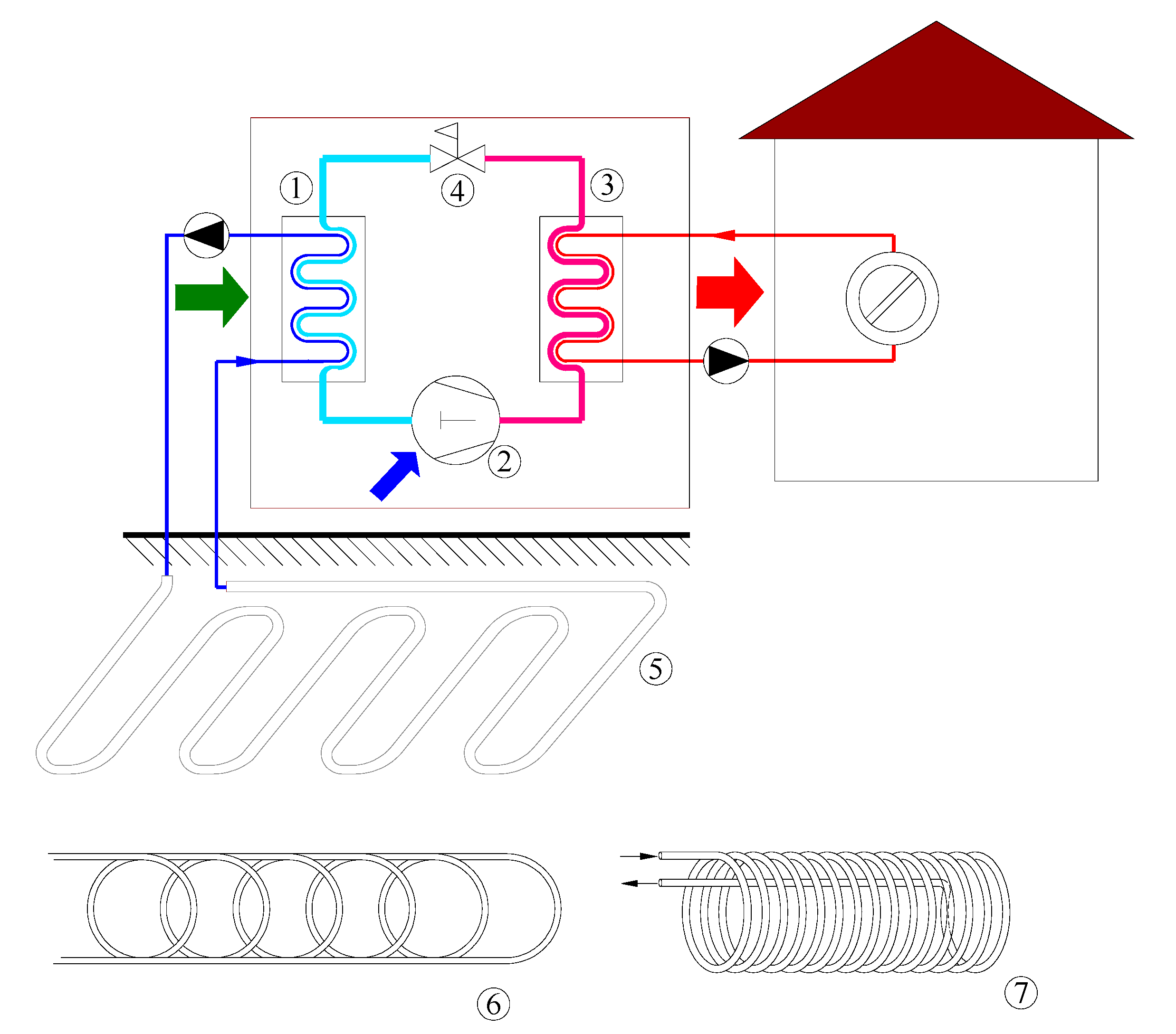
R&D in the field of ground physics allowed us to determine accurate soil temperature profiles and thermal properties. Modeling these properties in cooperation with advanced control systems and overcoming some of the design challenges was a prerequisite for use of direct expansion (DX) systems [87]. Compared to previously mentioned heat exchangers with water or glycol mixtures often used as indirect heat pump secondary circuit, DX systems act as evaporators or condensers of a heat pump whose working fluid is heat pump refrigerant (Figure 5). This setup removes the need for a heat exchanger between the fluid circles as well as a circulation pump. A ground heat exchanger design with the DX of refrigerant needs to follow some specific rules concerning the type of refrigerant, refrigerant charging, oil return to the compressor, depth of the vertical borehole heat exchanger, and possible ground pollution due to refrigerant leak [88]. The ground heat exchanger can be placed horizontally, vertically, or in a slinky manner. Exchangers with vertical configuration are predominant [36]. Several researchers have investigated dynamic heat transfer analysis of the two-phase flow in the ground evaporator and the heat exchange with ground [89,90,91,92]. De Carli et al. [89] developed the mathematical models of evaporation in the vertical U-tube. Li et al. [91] developed and validated numerically and experimentally a three-dimensional transient thermal resistance and capacity model of a novel direct expansion downhole heat exchanger. Additionally, Nguyen et al. [92] evaluated a pressure-enthalpy coupled thermal resistance and capacity model for a direct expansion vertical borehole heat exchanger for supercritical CO2 application.
4. Performance Indicators for the Evaluation of GHEs
Investigation of ground heat exchangers includes numerical studies and experimental studies conducted in the field or a laboratory environment. Experimental parametric analysis of different design aspects is sometimes used for simpler configurations of GHE like earth-to-air heat exchangers [12,93] or when parameters that are easily controlled are investigated, like inlet temperature and velocity [94,95,96,97]. In most studies, an experimental investigation is used for validation of developed models and numerical or analytical modeling is used to assess design aspects of GHE [11,64,98,99].
Different configurations are commonly investigated based on fluid outlet temperature or exchanged heat rate [16,58,61,100,101,102,103]. A temperature change of fluid flowing inside the GHE is also used [16,93,95], or difference between fluid and ground temperature [104]. Although the mentioned parameters indicate the better performing configuration, the initial and boundary conditions used in the analysis could shadow some of the conclusions made. For example, the fluid temperature change is strongly related to pipe length, while total exchanged heat flux can be increased with length only until the temperature difference between fluid and undisturbed ground exists. The spatial temperature distribution or fluid temperature profile gives insight into possible limitations of heat exchange that occur due to exhausted temperature difference [95] or thermal short-circuiting inside GHE [26,33,37,95,105,106]. For EAHE and HGHE systems, fluid temperature profiles are not of great interest unless used for more detailed validation of the models or the investigation of the surrounding soil’s influence on the GHE performance [10]. On the other hand, when direct expansion GHE systems are investigated, fluid temperature profiles are coupled with the pressure, density, and specific heat profile along the pipes, properties all affected by the phase change of refrigerant inside GHE [40,91,92]. Several authors used dimensionless temperature forms like thermal efficiency or effectiveness of the heat exchanger where temperatures Tin, Tout, and Tg are inlet, outlet, and ground temperatures [58,93,107,108]:
Pu et al. [18] defined dimensionless outlet temperature; the expression can be used only if there is a difference between inlet and ground temperature:
As for the heat flux, it is advisable to express the value per heat exchange surface [59] or even simpler per unit length [15,103,109]. Care must be taken, as unit length can be expressed as the pipe, vertical borehole, or horizontal trench length. When the heat exchange rate is expressed per trench, slinky or spiral configurations exhibit better value, while linear configurations show higher values of heat exchange per pipe length [11]. The choice of how to express a specific heat rate should be made following the definition of unit cost for the economic model. When relative initial costs were compared, spiral and vertical slinky configurations outperformed the linear type of GHE [11]. Heat flux as a performance indicator is limited to stationary or short-term analysis when average or peak values are identified. When the long-term performance of GHE is considered, exchanged heat energy and consumed electrical energy are more appropriate for performance evaluation [14,110].
Rodrigues et al. [9] and Brum et al. [111] defined a parameter called instantaneous thermal potential (P), based on the average temperature difference between the air inlet and air outlet temperature modeled by the sine-based function, to express monthly values of exchanged heat during long term operation. Temperatures Tin and Tout are inlet and outlet temperatures from GHE, while to and tn are the start and end of the observed period.
When GHE is operating under transient conditions, heat flux is affected by the cycling operation and thermal saturation of the ground [17]. Heat transfer during continuous and cycling operation can be compared using the overall heat transfer response suggested by Fujii et al. [112] and adopted by Ali et al. [15]:
QL is defined as a specific heat rate per unit tube length, while Tg and Tout are ground and outlet temperatures. If the value is integrated over a working period, a direct comparison between different operation modes can be made.
Selamat et al. [16] showed that effective heat exchange rate (the period between the effect of thermal capacities and soil saturation) is affected by the ground temperature surrounding and being almost independent of pipe layout, while overall heat exchange rate that takes into account the duration of operation period is strongly affected by GHE layout. Agrawal et al. [59] expressed deterioration in thermal performance of EAHE during operation due to soil thermal saturation with thermal performance deterioration factor (TPDF):
Temperatures Tin and Tout are inlet and outlet temperatures from GHE. The value of TPDF increases over time and is equal to 1 when soil is fully thermally saturated. A drawback of such an approach is limited use if inlet temperature changes over time.
When coupled with heat pump, GHE is often compared by the system coefficient of performance (COP):
where is condenser heat flux, compressor power, condenser fan power, and circulation pump power [103].
Hydraulic performance and pressure drop are important parameters that affect the running costs of the system. Still, they are often disregarded, except for the direct expansion system and DBHE systems. The pressure drop of GHE in the direct expansion system strongly affects the performance of the heat pump so it cannot be overlooked [36,102,113,114]. Flow performance and pressure drop in multi-tube configurations were numerically investigated by Amanowicz [19] in terms of the airflow uniformity coefficient for the section of the parallel pipe. Qi et al. [115] applied the same approach in their study and also defined analogous thermal performance uniformity coefficient. The COP of the EAHE system, expressed as exchanged heat and consumed power, points out the existence of optimum values of pipe diameter, meaning that larger does not always mean the better [107]. The pressure drop was indirectly taken into account during experiments by Agrawal et al. [59] by monitoring fan power consumption to express heat exchanger COP. DBHE are also systems where the pressure drop plays a significant role in the performance, whether the system is used for direct heating or coupled with a heat pump. Pump consumption and thermal performance of three different types (horizontal-, vertical-, multilateral-well) of the coaxial closed-loop geothermal systems were compared by Wang. He also compared the economic characteristics of different systems and proposed using energy, flow, and economic efficiencies to assess the feasibility of the systems [116]. The influence of pressure drop is considered when performance factors are used to evaluate system performance. For example, Huang et al. used the coefficient of system performance (CSP) to evaluate the efficiency of the DBHE system [117]. They defined CSP as a ratio of total heat extraction capacity and electricity consumed by circulating pumps the same way as Yao et al. [78] did, but they called it , and Chen et al. [118] defined COP as a measure for the same ratio. Chen et al. [118] also used CSP to evaluate the performance of DBHE coupled with a heat pump, but they defined CSP as a ratio of the amount of thermal power supplied to the building and electricity consumed by circulating pumps and the heat pump. Some authors use the performance efficiency coefficient (PEC), a dimensionless factor for the comparison of secondary working fluids, calculated as the ratio of heat transfer between the ground and the fluid of the test and base case divided by the pumping power ratio of the test and base case [119,120]:
Pérez-Tavernie et al. [121] compared the thermal performance and pressure drop of nanofluids by dimensionless thermal performance factor, defined as:
where and are Nusselt numbers of nano and base fluid, and and are Darcy friction factors of nano and base fluid. The authors stated that the thermal performance is conditioned by the enhancement of the convective heat transfer, but also by the increase of the pressure drop. Real applications are limited by those factors, and can simultaneously analyze both effects.
When GHE is coupled with a heat pump, several authors used COP values, defined as a ratio of exchanged heat and consumed power, as performance metrics [7,11,36,62,83,101,102]. COP values from different studies cannot be directly compared, as they are affected by heat pump characteristics and interaction with the underground as a heat source, and different authors tend to take different system parts (compressor, circulating pumps, fans) into consideration for consumed energy. Additionally, heat exchanger COP must be distinguished from COP of GHE coupled with the heat pump. When phase change materials (PCM) are utilized for GHE performance, improvement specific parameters related to the PCM can be used, such as liquid to solid ratio and absorbed heat [86,122]. As can be seen from literature, thermal performance is considered the most, followed by hydraulic and pressure considerations. Cost analysis of investigated systems is given in a few studies, but usually for a single GHE layout [84,86] and where drilling costs are very high (DBHE, BHE) [118,123]. An example of a working substance that is thermally very good, but economically difficult to apply was given by Diglio et al. [124] and Tarodiya et al. [95] in the form of nanofluids containing silver or multiwalled carbon nanotubes.
Another important parameter underrepresented in research is the impact of structural change on the environment. Full attention should be paid to this parameter when choosing the appropriate grout material as well as BHE fluid. Potential water or human health pollution risk is not allowed. Corrosivity, pH values, and heavy metal concentrations should be kept within the allowed interval [125,126]. Only a few authors raised a question and gave a numerical evaluation of the potential reduction of CO2 emissions using systems with GHE [27,127,128]. Life cycle cost and energy payback time analyses are also conducted by only a few authors recently [40,94,114,129]. Design optimization based only on thermal performance is not recommended, and running costs associated with pressured drop and investment costs need to be considered for a complete techno-economic approach.
5. Design Aspects of Ground Heat Exchangers
5.1. Backfill and Grouting Materials
When horizontal and shallow systems are considered, improvement of local geological conditions is possible if the secondary coating or backfill material with better thermal properties than the soil on location is used [10,11]. Backfill soil is used to enable good thermal contact with the surrounding ground and to secure the pipe slope [10]. Evaluation of the effect of the backfill soil and soil moisture on the thermal performance of EAHE showed that differences in thermal performance reached 15.9% for the same soil with different moisture content and 17.4% for different coating soils in a low humidity case [10]. High moisture content lowers the difference between coating soils to only 2%. The authors concluded that a choice of soil type for coating the EAHE makes a non-negligible influence on thermal performance, and the use of a coating soil that can store water is preferred [10]. Agrawal et al. investigated the effect of water impregnation on the thermal performance of EAHE as a measure to mitigate thermal saturation of soil during the heating [12] and cooling operation [13]. The authors installed two parallel systems at a depth of 3.7 m, with and without an irrigation system, each comprised of three PVC pipes with different diameters. The daily average heat transfer rate of EAHE in moist soil was improved between 22.7% and 24.1% during the cooling operation and between 15.6% and 22.8% during the heating operation, depending on moisture content (5–20%). Positive influence on thermal saturation is expressed as knee-point pipe length, at which 90% of total air temperature difference is obtained. Wet soil shifts the knee-point towards the pipe inlet, and knee-point position does not change over time, in contrast to dry soils, where thermal saturation results in shifting of the knee point towards the pipe outlet as operation time increases [12,13]. Habibi et al. [11] numerically investigated the performance of different horizontal GHE configurations and demonstrated the positive influence of the coating soil and soil moisture on the thermal performance of HGHE. Saturated secondary soil could reduce installation costs up to 40% [11]. The numerical results showed an energy enhancement from rainfall events: energy performance increases by 4% during the first 24 h after the beginning of the rainfall and about 2% after a further 24 h [14]. When the soil reached its maximum level of moisture, the exchanged power between the ground and the exchanger increased by 5–6% depending on the heating or cooling season. The authors also concluded that rainfall intensity has little impact on the EAHE’s energy performance compared to the cumulated rain precipitation [14]. Rodrigues et al. [9] numerically simulated the performance of EAHE in three different geotechnical profiles that include clays and sands with different water tables. Authors showed that high relative improvements (around 60%) can be achieved if the EAHE duct is installed on clayey soil layers, compared to sandy layers, even if better performing soil is closer to the surface. The quality of backfilling work can be considered as the soil compaction level, which was investigated by Elminshawy et al. [93]. In a laboratory experiment, heated air was blown through copper pipes inserted in a drum with sand. Three different compaction levels are used (void ratio of 0.88, 0.73, and 0.66). Higher compaction of the soils results in higher effectiveness of EAHE (18% difference between low and high soil compaction) and higher cooling capacity (48% difference between low and high soil compaction). In situ comparison of shallow systems with different backfilling materials (in situ material, clay powder, sand, and bentonite) was conducted by Bertermann et al. [104]. Comparison based on the temperature decline highlighted clay powder as the best option, despite not being the most expensive solution. The use of in situ material is the cheapest solution, but viable only if its reuse is possible due to the mechanical properties of the material.
For vertical BHE systems, the grouting material and process are extremely important. They enhance heat transfer and highly impact system efficiency. At the beginning of ground source heat pump usage, grouting was not placed in the annulus between pipes and the ground. Pipes were directly inserted into the underground water if accessible or dug into the ground and filled from the top. It was not until the 1980s that the idea of borehole grouting from the bottom upward came to light [130]. Backfill was introduced to enhance heat transfer between pipes and the surrounding soil. In addition to improving heat transfer, grouting acts as a support to other parts of the GHE system, which ensures stability and forms a hydraulic barrier that prevents pollution of the aquifers. The material must also have appropriate mechanical and thermal properties. There are a wide variety of backfill materials. Traditionally, two main components are bentonite and cement together with their mixtures [131]. Early state grouts, consisting of bentonite, cement, and water in approx. 1:1:2 ratio, respectively, had a thermal conductivity of 0.7 to 0.8 W m−1 K−1. As the technology has evolved, new materials were added to the grouts to enhance mechanical and thermal properties. It is important to emphasize that the grouting mixture is not perfected, and even with the use of well-known practices and good materials, the integrity of BHE cannot be guaranteed [132]. Besides grouting, improvement of local soil thermal conductivity can be achieved by the application of fillers. He and Bu [114] suggested using graphene and clay or cement and controlling the density, viscosity, and backpressure of the composite filler to allow it to flow into the leakages during the drilling process. Based on a simulation, they concluded that extracted thermal output can be 2.36 times higher than for the base case.
Bentonite is clay whose primary constituent is montmorillonite. Swelling is a pronounced characteristic of bentonite, as it can absorb several times its mass of water. Low permeability and self-sealing made it a good candidate for backfilling despite imperfect thermal properties. The dependence of bentonite thermal conductivity on the soil-water characteristic curve was experimentally tested by Kim et al. [133]. Molded specimens were left to dry at room temperature and change in thermal conductivity and volumetric water content was measured. With 20% of total weight, bentonites’ thermal conductivity reached a maximum of 0.93 W m−1 K−1 at 0.58 volumetric water content. For 30% of bentonite total weight, the maximum was 1.06 W m−1 K−1 at 0.51 volumetric water content. Results for bentonite–quartzite sand–water mixtures of different ratios are also presented. All the results show a parabolic relation of thermal conductivity to volumetric water content. An increased proportion of bentonite and sand led to an increase in conductivity and greater fluctuations with volumetric water content changes. Verdoya et al. [134] conducted laboratory and in situ experiments for two different commercial types of bentonite grouts. The first one was composed of bentonite and clay, while the second was a blend of blast furnace cement binders, including bentonite and fine sand of different granulations. The thermal conductivity and diffusivity of the first grout were 1.65 W m−1 K−1 and 0.61 µm2 s−1, respectively, while for the second grout, values were 2.13 W m−1 K−1 and 0.8 µm2 s−1, respectively. Various substances have been added to bentonite grout to improve its thermal properties. Blázquez et al. [131] tried to improve bentonite by adding aluminum shavings and sulpho-aluminate cement, resulting in a mixture of good mechanical properties with satisfying thermal conductivities of up to 1.566 W m−1 K−1. However, the contraction effect was very pronounced, and its influence grew with the increase of the bentonite content in the mixtures (up to 44%), so these materials were assessed as unacceptable for further use. Aluminum shavings and sand grouts yielded considerably better thermal conductivity values of up to 3.651 W m−1 K−1 with no contraction effect. Thermal properties were enhanced with just 1% of the aluminum total dry weight. Aluminum and sand derivatives were not the only known conductive fillers. Ground glass, fluorspar, steel grit, silicon carbide, etc., can be used as well. Very good results were observed with graphite supplement [125]. Adding carbon fiber to quartz sand–bentonite mixture is another option to enhance thermal properties. Carbon fibers have a thermal conductivity in the range from 100 to 1000 W m−1 K−1. Liu et al. [135] searched for optimal bentonite fraction in bentonite—carbon fiber—sand grout with constant carbon fraction of 0%, 1%, and 2% and moisture contents from 6% to 24% with a step of 2%. Results showed the best thermal properties at the bentonite fraction of 10% and 12% (dry mass) for all moisture and carbon contents. An improvement with an increase in sand particle concentration was also observed. Adding 2% of carbon fiber to the bentonite–sand mixture with 12% bentonite in dry mass increased thermal conductivity from 1.31 to 1.94 W m−1 K−1. This mixture had a very good compressive strength of 124–200 kPa. Very little research was done with bentonite as a grout base, since the last comprehensive review on this topic by Javadi et al. [136]. Their allegations that bentonite is gradually replaced with cementitious grouts can therefore be confirmed. The main reasons are great shrinkage accompanied by cracking and unsatisfactory thermal conductivity, which, despite the addition of expensive adulterants, does not exceed 2 W m−1 K−1. The thermal conductivity values of pure cement grout are in the range of 1 to 1.3 W m−1 K−1, which is slightly better than bentonite [125]. The material is cheap and easy to work with. Kim and Oh [137] measured specific-heat capacity and thermal conductivity of nine grout types with different silica sand, Portland cement, and water ratios in saturated, partially saturated, and air-dried conditions. In a partially saturated area, specific-heat capacity and thermal conductivity decreased linearly with a reduction in saturation degree. Specific-heat and thermal conductivity of air-dried mixtures decreased by 11.8–22.3% and 15.6–38.3%, respectively, compared to saturated conditions. Empirical equations predicting thermal conductivity and specific heat as a function of water/cement and sand/cement ratios were derived. Similar to bentonite, thermal properties are enhanced by the addition of conduction fillers. One option is to use waste materials to improve thermal properties. This way, the environment is preserved, as the leftovers of one process can help in another. The cost of these products is usually low. Used tires can be a source of graphene nanoplatelet obtained by pyrolysis [128]. In combination with silica hybrid additive, used to enhance the solubility and dispersion of carbon material, at the 5 wt% of hybrid-graphene, thermal conductivity increased to 1.82 and 2.34 W m−1 K−1 for the Si:graphene ratios of 1:5 and 1:10, respectively. In a study by Berktas et al. [138], expanded graphite base additives made by the synthesis of silica particles and expanded graphite were added to cementitious grout. With 5 wt% of additives in the mixture and functionalized silica aqueous solution to expanded graphite ratio of 1:5, the thermal conductivity of 2656 W m−1 K−1 was recorded. An increase in the additive loading ratio and expanded graphite content positively affected thermal conductivity. The combined effect of groundwater velocity impact and grouting materials in aquifers where water flow is not negligible was studied by Alberti et al. [139]. The study was conducted for surrounding soil formation backfill and thermally enhanced grout backfill at different groundwater flow rates. The peculiarity of this research is that, unlike other studies that focus only on thermal conductivity, it also examines the combined effect of hydraulic conductivity. Grouts are characterized by a low hydraulic conductivity, which is highlighted when there is significant water flow. Thermally enhanced grout did not show improvement compared to the base case filled with the surrounding soil. The reason is lower hydraulic conductivity of thermally enhanced material.
The addition of phase change materials (PCM) is a new, efficient means of energy utilization, enhancing the thermal properties of a grout. PCM is used as latent heat thermal storage and can reduce annular and surrounding soil temperature fluctuations. During the cooling cycle, PCM melts, and with its latent heat maintains an almost constant temperature of soil surrounding the BHE. During off periods, PCM solidifies. Changing the physical state is crucial for the proper implementation of these materials, which is why attention should be focused on the phase change temperature (PCT). It is recommended to use several PCM materials with different PCT to cover a greater operating temperature range, i.e., heating and cooling periods [140]. The term PCM corresponds to a wide variety of materials categorized into organic, inorganic, solid-solid, and hygroscopic materials. For GSHP applications, organic PCM like paraffin is the most common choice [97]. Apart from appropriate PCT, PCM should have high thermal conductivity and large latent heat, and it must be non-corrosive, chemically and mechanically stable, and cheap [96]. It is not possible to meet all the conditions, so additives are selected to compensate for certain inadequate properties of PCM. The main disadvantage of these materials is their low thermal conductivity. PCM alone cannot quickly absorb or release heat, which is why they are usually combined with highly conductive materials. In the numerical study by Javadi et al. [97] nanoparticles like Cu, CuO, Al2O3, TiO2, SiO2, multi-wall carbon nanotubes, and graphene were mixed into a paraffin base. The best results were shown for Cu, so copper nanoparticles were used for subsequent research. As could be assumed, an increase in the proportion of Cu particles leads to a higher melting rate of PCM. For the 0.2 volume fraction of nanoparticles, thermal conductivity is improved by 55% compared to pure paraffin. Nanoparticles should be blade-shaped for the best results. Both cooling and heating conditions were experimentally tested by Yang et al. [96]. For the summer period, a mixture composed of decyl and lauric acids in a mass ratio of 66:34, respectively, was used (PCT: 20.55 °C and latent heat: 133.65 kJ kg−1). For cold, winter conditions, oleic acid (PCT: 8.11 °C and latent heat: 94.51 kJ kg−1) was used. The soil thermal interface radius was reduced by 13.5% in cooling and 12.2% in heating mode. Heat transfer rates were increased by 9.4% cooling and 28% heating when compared to the soil backfill. The effects of PCM usage on the efficiency of GSHP considering the dynamical loads and site conditions are described in the numerical study by Chen et al. [108]. It is stated that pure paraffin due to its poor thermal properties causes heat accumulation within BHE. The result is a reduction in the efficiency of the heat pump. When shape stabilized PCM is added to the grout, the heat pump works more stably and efficiently. Results of the study also point out that the efficiency is improved by enlarging the intermittent ratio, and the effect on the surrounding soil is reduced. The impact of running modes on the restoration performance of the heat pump with PCM was studied by Chen et al. [141]. As the working schedule highly influences sustainability and operating stability, PCM materials should be used in buildings where demand is less persistent. The most effective way to improve stability and sustainability is to alternate the heating and cooling load periods.
There are a large number of materials that can be used for backfilling and choosing the right one is complex and complicated. The selection itself is based on the required heat flow, the condition of the surrounding soil, safety requirements, operating temperatures, and other conditions. The right material will lead to a reduction in the total length of the borehole, which is equivalent to a reduction in the investment cost of setting up the system.
5.2. Pipe Arrangement and Material
For better performance of GHE systems and cost-saving in installation and operation, as mentioned, the grout material and pipe material are very important factors [130]. The most used materials in the piping of GHE are divided into two categories: metals and thermoplastics. When considering metals as a material for pipes of GHE, several things must be addressed. Metals have to be resistant to corrosion (both surfaces—in contact with the fluid and with the grouting) and stress corrosion cracking to achieve a long-life span. The cheapest basic mild steel must have cathodic protection to avoid corrosion or must be galvanized or externally coated. Stainless steel, nickel, aluminum, copper, titanium, and their alloys are more corrosion resistant but have higher prices [142]. Although thermoplastics have lower thermal conductivity than metals, they are widely used because of their low cost, availability, corrosion resistance, and practicality. From the wide range of available plastics, high-density polyethylene (HDPE) is most commonly used, followed by polyvinylchloride (PVC) [54]. Other used thermoplastics are polypropylene (PP), polyurethane (PU), and polybutylene (PB). To increase the thermal conductivity of the most represented HDPE, the secondary material of high thermal conductivity is mixed in the polymer matrix [142,143]. The combination of the thermal conductivity of the pipe material and grout should be optimized to match the thermal characteristics of the ground to achieve the best economical and thermal performance of the system [130].
When EAHE systems are considered larger, the pipe diameter, higher heating/cooling capacity, and lower heat exchange effectiveness can be expected [3]. Still, if COP is defined as heating/cooling capacity and fan power is observed, for each set of inlet conditions, optimal pipe diameter can be defined [17]. Pipe length is the key factor that affects the performance of EAHE in terms of sizing the system for cooling or heating operation. An increase in pipe length positively affects heat transfer and heat exchange effectiveness, as long as there is a temperature difference between soil and air [18], but it also negatively affects the pressure drop, again pointing at the possible existence of the optimum value [17]. Interestingly, pipe material (PVC, steel, copper) has a negligible effect on the performance of EAHE; therefore, the material choice should be based on economical and hygiene aspects [17,19]. In contrast to single pipe configuration, some researchers investigated the characteristics of multi-pipe configurations. Airflow delivered by the main pipe is distributed to parallel pipes in the main section, resulting in a lowered pressured drop. When the connection of parallel pipes to the main pipe is considered, a U-type connection is preferred over a Z-type due to the smaller pressure drop (up to 36% difference) and more uniform air flow distribution (up to 80% higher uniformity), while diameter ratio of the main pipe to parallel pipes larger than 1 positively affects the pressure drop [19]. This analysis was further improved by Qi et al. [115] by the inclusion of L-type and I-type configurations. I-type showed the worst performance, while L-type showed better airflow uniformity performance and heat transfer performance than U-type. Compared to the Z-type, the heat transfer rate of L-type and U-type structure EAHE was increased by 5.5% and 5.8%, respectively. The authors defined the integral evaluation factor that considers thermal and pressure drop characteristics and noted that the optimal value of diameter ratio of the main pipe to parallel pipes exists between ratio values of 1 to 2. Brum et al. [111] investigated the effect of the horizontal and vertical arrangement of multi-pipe configuration (up to five pipes). The EAHE performance can be improved by increasing the volume occupied by the installations and by placing the pipes further apart in the horizontal direction than in the vertical one. A simple addition of pipes in installations does not mean a superior performance if no care is given to their geometrical disposition. Improvement of EAHE performance with phase change materials is suggested by several authors. Zhou et al. [122] constructed an experimental rig with three concentric 2.5 m long pipes, two inner stainless steel pipes, and one outer U-PVC pipe. The space between the U-PVC tube and the stainless steel was filled with wet sand. The space between the two stainless steel pipes was filled with a laboratory-prepared shape-stabilized phase change material. The experimental set up was used to validate the effective heat capacity model developed in Ansys Fluent. In the cooling season, the outlet temperature of the PCM-filled EAHE was found to be approximately 0.83 °C lower than that of the traditional EAHE, resulting in an improvement of 20.24% in cooling capacity. Performance can be increased even further by optimization of geometric parameters and operation strategies [122]. System optimization is highlighted in studies conducted by Lie et al. [127], where a novel vertical arrangement of EAHE with annular PCM was proposed. A system equipped with PCM enables an air temperature decrease of approximately 30% compared to the system without PCM. The authors also investigated the influence of PCM thickness and concluded that in the observed case, there is limited performance improvement if PCM thickness greater than 5 mm is used. Vertically buried U-tube configuration has an advantage over conventional EAHE systems due to its smaller land use and more efficient usage of geothermal energy from deep soil during operation. Throughout the whole monitoring period, the outlet air temperature ranges from 22.4 to 24.4 °C in summer, and from 16.0 to 18.0 °C in winter, regardless of the inlet temperature [94].
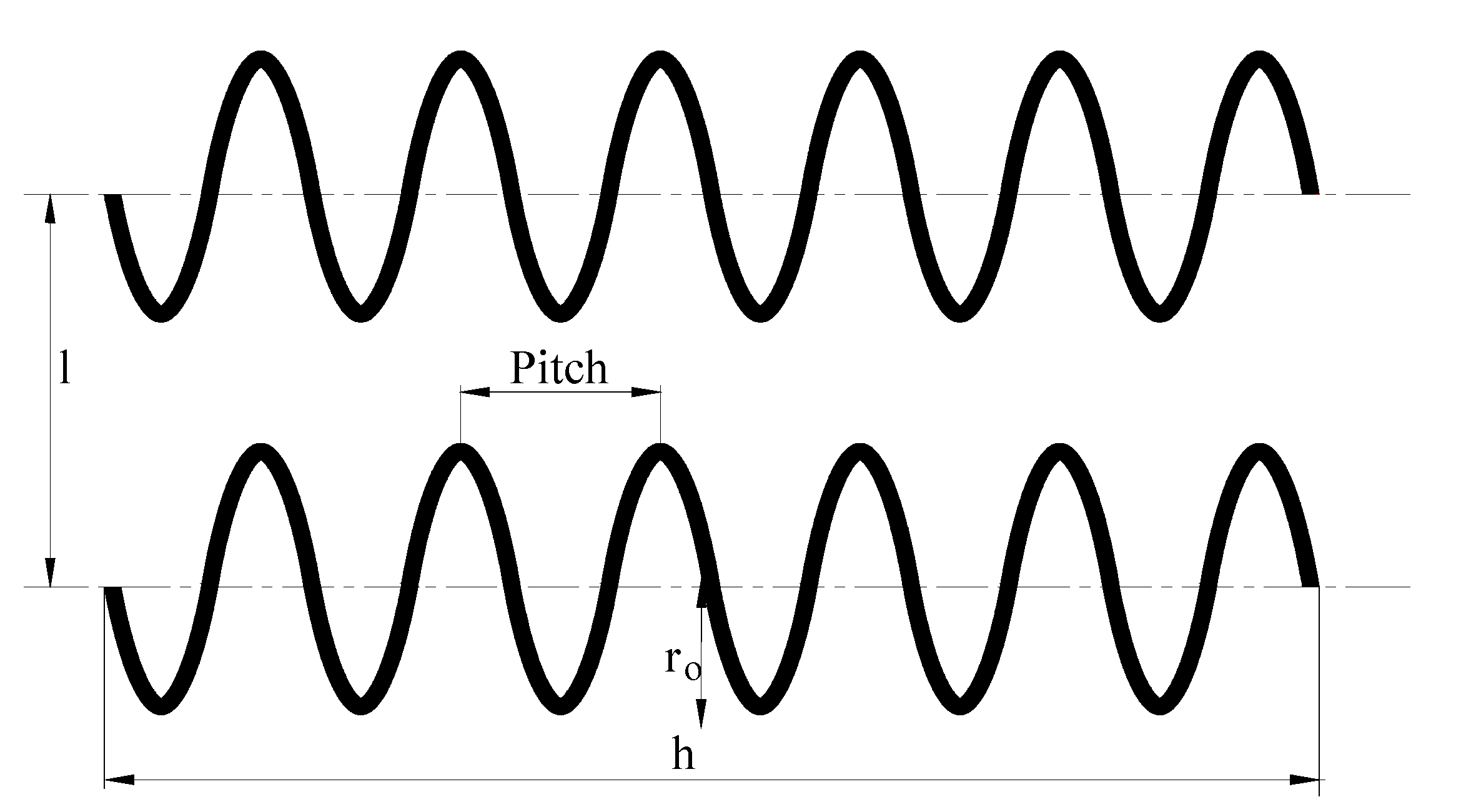
Different horizontal GHE configurations (linear, spiral, horizontal slinky, and vertical slinky) made of PE pipes and using water as circulating fluid were numerically investigated by Habibi et al. [11]. For a single arrangement, slinky configurations have the highest heat exchange rate per meter length of the trench, while spiral configurations have the lowest initial cost. If the heat exchange rate is expressed per meter of the pipe, modified linear multi-tube configurations exhibit better performance than slinky or spiral type [144]. Pu et al. [18] used numerical simulation to evaluate different configurations of linear HGHE. Water was used as the working fluid and PE100 was used as the pipe material. If the serpentine configuration is used, thermal interference lowers the heat exchange rate compared to the straight pipe by up to 60%, and pipe spacing of 40–60 times larger than pipe diameter is suggested. The authors also compared different layouts of double-layered HGHE: inline (parallel) and staggered arrangement. The staggered arrangement proved to be beneficial to the exchanged heat transfer rate if the horizontal offset is larger than 1/3 of the value of the distance between upper and lower pipes. A larger ratio of the offset to vertical distance results in smaller thermal interference: for a ratio equal to 1, the heat transfer rate was improved by 47%. Authors conclude that pipe spacing has a noticeably stronger influence on the thermal performance of HGHE compared to the installation depth [18]. The preferable direction of heat-medium circulation in double-layer configurations is circulation from the upper layer to the lower layer [112]. Selamat et al. [16] conducted a transient numerical simulation of linear and slinky HGHEs with HDPE, copper, and composite (copper and LDPE) pipe materials. In terms of the maximum heat exchange rate expressed per length of a trench (all configurations are installed in a 7-m long trench), there was no significant difference between linear and horizontal slinky configuration regardless of pipe material. Vertical slinky configuration outperformed horizontal configurations by 15%. In a transient operation, the linear configuration has a larger initial heat exchange rate (up to 42% difference), but the drawback of this configuration is earlier soil thermal saturation compared to other configurations. The effective working period, before thermal saturation occurs, can be improved by using materials with superior thermal conductivity, like copper (effective period increased by 16% compared to HDPE pipe) [16]. Composite (copper and LDPE) pipe material was used in the experimental study where the performance of vertical and horizontal slinky HGHE is investigated. The average heat exchange rate was 16.0% higher for the vertical slinky HGHE than the horizontal slinky HGHE at a flow rate of 1 L min−1 and 19.1% higher for the mass flow rate of 2 L min−1 [15]. Kim et al. [64] showed that the spiral type of HGHE has a 10–11% higher heat exchange rate compared to a horizontal slinky configuration in low thermal conductivity soil (up to 1 W m−1 K−1) and that the influence of pipe diameter is negligible compared to soil properties. Sensitivity analysis showed that soil thermal properties have the largest influence on thermal performance, followed by pipe spacing [7]. The same analysis noted that the difference in thermal performance diminishes for soil conductivities larger than 1.5 W m−1 K−1. Kim et al. [100] investigated geometric parameters of the spiral-coil heat exchanger made of PB pipes. Spiral pitch is identified as the most influential parameter that should be increased to lower the thermal interference (Figure 6). Spiral diameter can be used to compensate the installation area, as it does not significantly affect the thermal performance of a horizontal spiral-coil GHE.
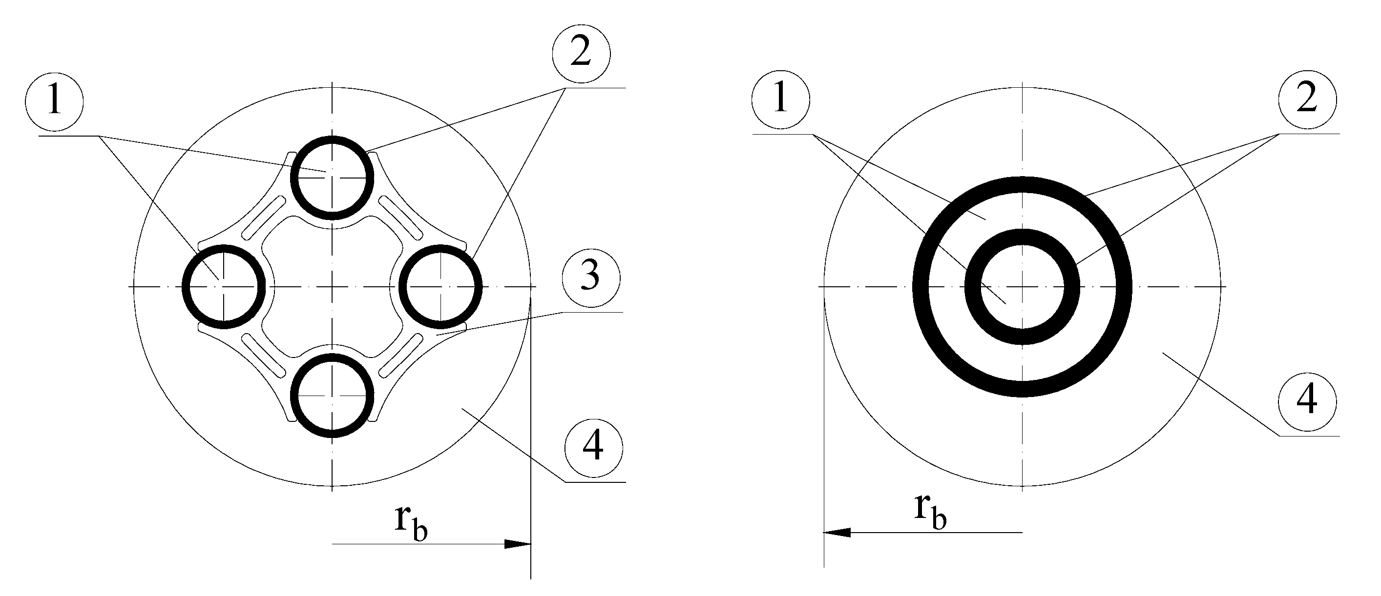
Considering vertical GHE, two commonly used configurations are various U-tube configurations and coaxial BHE (Figure 7). From previous studies, it was known that a double U-tube offers better thermal performance than a single U-tube while being more expensive. Shallower coaxial BHEs have also been included in several studies. It was concluded that the most influential factors on the performance of coaxial BHE were flow direction of circulating fluid, circulating fluid flow rate, and inner and outer tube diameter [43,54]. Investigation of the impact factors influencing the performance of shallow BHE was conducted by Tang and Nowamooz [101]. Variation in performance is mostly influenced by meteorological conditions, grout thermal conductivity, and heat load level (27.2%) followed by carrying fluid velocity and multi-pipe solution (12.2% and 16.2%). Hydraulic conditions, grout volumetric heat capacity, grout diameter, shank spacing, inner pipe diameter, pipe thickness, carrying fluid material, and pipe thermal conductivity have less impact on heat pump COP (between 0% and 11.6%). Energy performance of coaxial and double U-tube BHE has been compared by Quaggiotto et al. [145] using numerical simulation in the long- and short-term. They concluded that under equal boundary conditions, coaxial BHE exchanges 2.9–5.5% more energy in heating mode and 0–1.6% more energy in the cooling mode than double U-tube when ground thermal conductivity is 1.1 W m−1 K−1). With an increased thermal conductivity of the ground, even better thermal performance of the coaxial BHE is achieved. Gordon et al. [24] in their paper presented the effects of using an insulated inner pipe and steel outer pipe on the performance of coaxial BHE compared to HDPE pipe as the baseline case. With the developed semi-analytical model (composite coaxial model), it was concluded that the steel outer pipe has a better influence on reducing the overall length of BHE than using an insulated inner pipe. Gordon et al. [146] also concluded based on an experimental and analytical investigation that for a constant outer diameter, increasing the inner diameter provides better performance of the system while balancing pressure drops. Mu Bae et al. [147] performed an experimental evaluation of four different GHE under the same ground conditions. In the experiment, they used HDPE type, HDPE-nano type, spiral fin type, and coaxial type GHE and evaluated their thermal performance by measuring the inlet and outlet temperature of circulating fluid, calculating effective thermal conductivity by using the thermal response test (TRT). The result of experiments showed that coaxial type GHE has the highest borehole thermal resistance, and borehole thermal resistance of the HDPE-nano type and spiral fin type was smaller by 1.02% and 1.13% compared to the conventional HDPE type. Experiment analysis on the effects of pipe diameter and pipe material on the performance of coaxial BHE was conducted by Oh et al. [25]. The experiment showed that increasing the thermal conductivity of the outer pipe material increases the amount of exchanged heat. Authors argue that choosing the right material for the outer pipe should be a trade-off between performance and cost. Regarding the pipe diameter, they concluded that increasing the diameter increases the amount of exchanged heat, but the increase is not proportional, so they suggest determining the optimal diameter ratio of the inner to the outer pipe. Using multiple BHE with different connection configurations was investigated by Qi et al. [20]. With a combination of mathematical modeling and experimentation, it was concluded that parallel connection offers a 4.8% higher value of COP and 22% higher heat load to pumping power ratio while also having a lower pressure drop. Improving the thermal performance of vertical GHE by using an elliptical U-tube has been investigated by Jahanbin [148]. Compared to typical U-tubes, elliptical U-tubes offer 17% lower thermal borehole resistance, which can lead to an improvement of the COP of GCHP. The impact on the performance of internal and external fins has been investigated by Zanjani et al. through dynamic and static simulations [149]. Results showed that with increasing inlet fluid velocity, the fluid temperature of the internally finned U-tube is increased by 5–11.3% and 0.5–2.9% by the externally finned tube compared to the simple U-tube. The authors concluded that by using fins, the length of tubes can be reduced, thus decreasing initial cost. To assess energy efficiency, the overall GSHP system pressure drop has to be considered. Kurevija et al. [150], by using a thermal response step test (TRST), compared three different types of U-tube BHE. Results showed that the 1U-loop D45 ribbed pipe has 6.5% and the 2U-loop D32 ribbed pipe has 18.7% higher heat extraction compared to 2U-loop D32 smooth pipe.
The pipe arrangement and material of DBHE have not been explored very much. Due to the fact that maximum temperature is achieved at bottom of the DBHE [30], and to avoid thermal short-circuiting between upward and downward-flowing fluid, which will decrease the outlet temperature and thus thermal performance, the authors suggested reducing inner pipe conductivity [30,33,123,151]. Song et al. [29] stated that there is an optimal insulation section of the central tube because when the depth of the borehole is more than 4500 m, there is a minor change in outlet temperature. The same authors argued that there is an optimum length when using high thermal conductivity cement because most of the heat is exchanged in deeper parts of the reservoir. Sliwa et al. [152] suggested using a vacuum insolating tube as the inner tube of DBHE. Analysis of using vacuum insulated tubing (VIT) was also undertaken by Kalmar et al. [153]. Avoiding thermal short-circuiting and increasing performance of DBHE can be also achieved by decreasing the inner pipe diameter (increasing velocity), but that requires more pumping power, which can decrease system efficiency [30,123]. Increasing the outer pipe diameter would increase the heat transfer area and improve the thermal performance of DBHE, but financial aspects of drilling at high depth should be considered [30,77,154]. Regarding the material of the outer pipe, the authors suggested that is better to apply a thermally enhanced grout material than to use a high conductivity outer pipe [77,154] because outer pipe conductivity does not have much influence on performance since the thermal resistance of the ground plays a dominant role [32,77,118]. Different types of deep coaxial GHE are compared by Wang et al. [116]. They compared energy efficiency (energy output–energy consumption) of vertical, horizontal, and multilateral wells, and concluded that the multilateral well has the best energy efficiency and best economic efficiency, followed by the vertical and horizontal well. Increasing depth can improve the heat extraction rate. Pan et al. [154], for example, showed that increasing the depth of BHE from 500 to 1000 m can improve the heat extraction rate by 30%. Deng et al. [77] also concluded that increasing the depth of BHE leads to higher outlet temperature and higher average heat extraction. When increasing depth, the authors suggested that the economical side of the system has to be considered [123,153]. Some authors [32,33,151] concluded that better performance in heat extraction mode is achieved when circulating fluid flows down through the outer pipe and flows back upward through the inner pipe, despite the borehole depth. Inlet temperature does not have much effect on the performance of DBHE [30], but a larger temperature difference between soil and circulating fluid increases heat transfer [29]. The inlet flow rate affects heat transfer, so with a higher flow rate, the outer temperature declines and thermal power increases, so it is necessary to find the optimum between pressure drop (pumping power) and thermal performance [29,30,78].
When shallow systems are considered, there is a noticeable difference in energy piles and shallow borehole or basket configurations. Depth, number, and distance between energy piles are defined by the piles’ layout and building construction requirements. Materials used for pile construction are cast-in-situ concrete pile, prestressed high strength concrete (PHC), and steel pile, while heat exchanger pipe material and layout are similar to the vertical ground heat exchangers. Pipe arrangement can be classified as single or multiple U-pipe, coaxial pipe, and helical pipe [51]. Most reported energy piles’ investigations include piles with depths from 10 to 30 m and diameters from 0.3 to 0.9 m [49].
A numerical study conducted on a shallow vertical 20-m-deep U-pipe configuration showed that the influence of pipe thermal conductivity diminished for values above 2 W m−1 K−1 and that multiple U-pipe solution with cross-connection is preferred over a single U-tube or parallel pipe configuration [101]. Several case studies confirmed the potential of a simple coil configuration for GHE application [84,155]. Helical coils are usually made of HDPE pipes with an outer diameter ranging from 22 to 32 cm with a total pipe length from 40 to 110 m [83,84,155]. Aspect ratio expressed as a ratio of installed length and coil diameter ranges from 1 to 30. A numerical model of the helical coil was developed by Agbossou et al. [82] to investigate operating modes and heat exchanger spacing. The authors used a 3.14 long exchanger with a coil diameter of 1 m (HDPE pipe). Results showed that intermittent operation is advisable to limit thermal saturation of the ground, while the minimal spacing between two adjacent heat exchangers should be four times larger than the diameter for the line and square configuration and six times larger in case of hexagonal configuration.
Considering DX-GSHP, the usual configuration considers a double or triple U-pipe whose borehole depth of heat exchangers varies between 10 and 30 m and the diameter between 112 and 300 mm. The borehole pipes must be well designed so that the minimum refrigerant velocity is sufficient to return the oil to the compressor. On the other hand, the pressure drop should be below the recommended limits. The critical pipe is the ascending leg of BHE. The minimum refrigerant velocity for this section is 7 m s−1. The material of the pipe is copper in the range of 12 to 19 mm of outer diameter. In some cases, the descending leg with more content of liquid has a smaller diameter compared to the ascending leg with more content of vapor [88]. Higher exergy efficiency was achieved for space heating domestic hot water by using an expander compared to an expansion valve in a horizontal configuration of DX-GSHP [39]. Slinky horizontal and vertical configurations with DX-GSHP achieved 8% and 12% better EER compared to conventional air conditioning, respectively [40].
5.3. Working Fluids
In ground-to-air heat exchangers, outside air is heated or cooled by exchanging heat with the underground. An increase in the airflow rate in pipes increases the cooling capacity but lowers the heat exchanger effectiveness [93]. A similar effect related to the air velocity is found by other researchers when thermal performance was analyzed [59]. An increase in air velocity increases the heat transfer rate and pressure drop. By analyzing the coefficient of performance (COP), defined as heating/cooling capacity and fan power, it was demonstrated that an increase of the air velocity from 1 to 4 m s−1 almost halves the COP value from 0.92 to 0.57, due to increased fan power [107]. Lin et al. [110] compared the long-term performance of heat exchangers in soils with different moisture content. For systems with low air velocity (0.51 m s−1), the difference in extracted energy was less than 5% between dry and saturated conditions. By increasing the air velocity to 4 m s−1, the difference is increased to 46.4% in the heating and 42.4% in the cooling operation. An often disregarded aspect of using outside air as working fluid is possible latent heat exchange occurring in pipes, which can cancel the positive effects of sensible heat transfer [156].
It is also possible to direct the working substance directly to the BHE. Various refrigerants have been investigated as working fluid in DX-GSHP. At the beginning of the application, researchers started with CFC (R11 and R12), followed by HCFC (R22) and HFC (R134a, R410A, and R407C) refrigerant. Today, studies mainly use natural refrigerants, CO2, due to the risk of environmental pollution. Compared to HFC refrigerants like R134a, R410A, R407C, and R1234yf and HCFC-22, CO2 requires smaller pipe dimensions, mass flow rate, and four to seven times less power for circulation at the required capacity [36,99,157]. The transient coupled model is developed to describe subcritical and transcritical cycles under various controls and building loads [37].
Most systems use heat carriers in a secondary loop. They have the essential task of transferring heat from the ground to the heat pump system and vice versa. The most commonly used heat carrier in a BHE is water [95]. Its low price and relatively good thermal properties meet the set criteria in most cases. The problem occurs under the cold temperatures under 0 °C when water starts to freeze. If those conditions are possible, water-glycol mixtures are used in horizontal, shallow, and vertical GHE systems. Propylene glycol is prioritized over ethylene due to lower toxicity, and calcium or sodium chloride solutions could also be used, but are less frequent [121,126]. Calcium chloride as a working fluid positively affects the GHE performance compared to the propylene and ethylene glycol mixtures with similar freezing temperatures [101]. As the properties of the pure secondary fluids are very well known, the emphasis of this paper is on the newer nanoparticle fluids and other interesting heat carrier solutions, for example, non-Newtonian fluids, which are simulated by Valizadeh et al. [158]. They investigated the heat transfer characteristics and pressure drop of non-Newtonian turbulent flow in spiral tubes.
Technological advances in the field of heat transfer led to rapid improvement of the heating apparatus, as researchers started adding nanoparticles to the base fluid to improve heat transfer. This combination of nanoparticles in the base fluid is called nanofluid. It is not easy to correctly choose the combination of base and nanoparticles [95]. Many parameters affect the choice, and some of them are thermal conductivity, viscosity, density, and specific heat [95,121]. Researchers discovered that adding the nanoparticles to the base fluid improves the thermal conductivity of the mixture by the phenomena of liquid layering at the fluid particle interface, Brownian motion, thermal diffusion, and cluster agglomeration [121,159]. Increasing the share of nanoparticles results in a greater pressure drop, and exit temperature (heating); increased viscosity, shear stress, and density; and reduced pipe length compared to the base fluid [95,121,159,160]. Six different nanoparticles in different volumetric concentrations with water as a base fluid were investigated by Tarodiya et al. [95] to determine the benefits of their incorporation in terms of reducing the total length of a borehole, optimal flow, pressure drop, etc. Nanofluid with graphite-based nanoparticles showed the best results by minimizing the pipe length and pressure drop. The study confirmed that the positive effects of nanofluids decrease by reducing the difference between inlet and soil temperature as well as with the increase in flow rate. Benefits are more pronounced with an increase in pipe radius and borehole depth. The impact of CuO nanoparticles diameter and sphericity in a water solution on the thermal performance of GSHE was numerically investigated by Du et al. [119]. Six different particle sizes in two shapes, spherical and rod, were compared by the performance efficiency coefficient defined as a ratio of heat transferred by the nanofluid compared to pure water, divided by the ratio of pressure drop of nanofluid and water. Spherical nanoparticles with a 40 nm radius showed the best results. Larger particles sedimented at the bottom of the borehole faster, after only several hours of system shutdown, but were washed out after only several minutes from restarting the process [161]. Graphite nanoplatelets can also be dispersed in a propylene glycol/water mixture. Taverniera et al. [121] experimentally tested four different wt% of functionalized graphene nanoplatelets in a 30:70 wt% base fluid. Results showed a maximum increase in heat transfer coefficient at the 20 °C for 0.75 wt% concentration of nanoparticles. By incorporating the pressure drop into the analysis, the best results were obtained by 0.5 wt%. Kapıcıoğlu and Essen [103] examined Al2O3/ethylene glycol–water mixture (25% concentration ratio of ethylene glycol) in a horizontal ground heat exchanger. Tested nanoparticle concentrations were 0.1% and 0.2% in both U-type and spiral GHE. The nanofluid with a particle concentration of 0.1% showed a performance increase of 19% compared to the base fluid in a U-tube GHE and 21% in a spiral GHE. Improvements in heat transfer were 2% and 3.2%, and in COP increased by 2.5% and 3% for U-tube and spiral GHE, respectively. A higher concentration of 0.2% showed worse results, probably due to greater required pumping power. If, after excluding the fluids that do not meet the set requirements, several options remain, it is necessary to conduct an economic analysis. When water is used, the capital costs of the heat carrier are around 3 € m−1, while, for example, nanofluid with copper raises the price interval to 4–10 € m−1 for nanoparticle concentrations in the range 0.1–1% [124]. After choosing the appropriate fluid, it is important to correctly determine its flow rate. Hydraulic assessment will find a balance between thermal efficiency and operating costs that both increase with increasing flow. Greater thermal efficiency means lower initial costs [109].
6. Conclusions
Geothermal energy is a widely available, constant source of renewable energy that has great potential as an alternative source of energy in achieving global energy sustainability and environmental protection. When heating or cooling of the buildings is considered, a ground heat exchanger (GHE) is the most important component for efficient system performance. Several different options of GHEs are recognized based on the type of installation: horizontal, vertical, shallow, and DX systems. For the investigation of GHEs, numerical simulations are the most common type of study, followed by field and laboratory experiments and analytical studies where the ratio of numerical versus experimental is in close relation to the simplicity and cost of the application of the GHE system. Numerical studies mostly investigate the performance of GHE for stationary or semi-transient conditions. When the dynamic or transient simulation is conducted, additional conclusions can be made. For example, the pipe material in horizontal GHE systems has a negligible influence on thermal performance based on stationary conditions, while transient analysis showed that the pipe material has a great impact on soil thermal saturation. It is also noted that most of the studies investigate only the thermal performance of GHE, and conclusions could be misleading, as thermal performance and pump/fan power are differently affected by fluid velocity, pipe diameter, pipe length, pipe roughness, etc. Common components of all GHE are working fluids, pipes (dimensions, materials, and arrangement), and backfill and grouting materials, which are, at the same time, parameters that can be improved to achieve better thermal performance. Thermal performance improvement of GHE can be done by addressing influential factors, but some limitations have to be considered. One of the most important limitations is the availability and price of material because if the cost is not justified from an economical point of view, there is no point in using it. Other limitations, such as environmental impact, durability, and feasibility, should also be considered.
The first assumption when comparing results of different papers is that they are processed in the prescribed manner. As seen in the performance indicators section, this is not the case. In contrast, many similar parameters that describe the operation of the system are used. Another problem is the assignment of the same name to differently defined parameters. A well-known example is the inconsistent definition of the coefficient of performance (COP), where certain authors do not consider the operational power consumption of pumps or fans. Some authors are neglecting the importance of the economic feasibility of system performance in their analyses and focus exclusively on thermal performance. Although from the technological point of view, those studies yield the best results, for the wide application of the new technology, a competent techno-economic analysis is needed.
Improving the thermal conductivity of the grouting improves heat transfer from the soil to the working fluid. Apart from good thermal conductivity, grouting has to have low permeability and good self-sealing properties and has to ensure the mechanical stability of the BHE. On the other hand, improving grouting should be done carefully and economically (it is very important to include the cost of material in the analysis), because improving thermal conductivity can lead to higher capital cost, and the thermal performance of GHE cannot be improved unlimitedly. Grouting improvement exhibits an asymptotic effect on thermal performance, and in some cases can even degrade performance (due to thermal short-circuit on U-tube BHE). Most studies in recent years have focused on modern PCM materials compared to conventional bentonite and cement mixtures. Used as latent thermal energy storage, PCM reduces annular and surrounding soil temperature fluctuations, which positively affects GHE performance.
As for the working fluids, refrigerants in direct expansion systems show better thermal performance than working fluids in indirect systems. Traditionally, in indirect systems, water is the preferred GSHE working fluid due to its high thermal properties, negligible environmental impact, and low price. At low temperatures, the working fluid must not freeze, which is why the water is replaced (mixed), usually with glycol mixtures. Most of the new studies are focused on nanofluids, a combination of nanoparticles in the base fluid. They show improved thermal properties with very low concentrations of 0.1 wt% and are rarely used in concentrations greater than 1 wt%. Although nanofluids show great potential in thermal performance, their negative sides (higher pressure drop, higher price, and loosing of nanofluids due to a leakage) limit wider use.
Pipes for GHE should be chemically stable (copper tubes for direct expansion systems), corrosion-resistant, and easy to use with good thermal conductivity. Improving the depth and heat exchange area of GHE improves the stability and performance of GHE, but at the same time increases capital and operational cost and raises the question of the long-term stability of the ground. When construction improvements of pipes are made, it is important to analyze hydraulic and pressure characteristics, which can often present substantial limitations. Choosing the right pipe material can improve the performance of GHE and reduce installation costs. Depending on the type of heat exchanger, improving the thermal conductivity of pipe material can improve the performance of GHE (horizontal configurations, vertical configurations,) or does not have a significant impact on performance and only increases investment (EAHE, the outer tube of DBHE).
As for the design of horizontal GHE systems, greater spacing between pipes, advanced multi-tube configurations or spiral configuration, secondary coating soil, and moisture retention improve the thermal performance of GHE. The depth of the installation is an influential parameter only if there is a significant difference in ground properties. Seasonal temperature variations do not significantly affect the performance of GHE in shallow soil. Shallow GHE systems including energy piles and basket configurations are becoming more popular due to more stable underground conditions and more cost-effective installation than vertical configurations. Coil configurations have a larger pressure drop, but that can be compensated for by larger inner pipe diameter and a coil diameter of spiral configuration. The effect of helix pitch is negligible.
New advancements considering vertical GHE systems try to further improve classical U-tube arrangements by using various new geometries and fins to improve thermal performance and reduce the length of the borehole, thus reducing high drilling costs, which can make the technology of GSHP even more commercially available. The relatively new application of deep borehole heat exchangers has shown great potential, as they offer better performance than shallow BHE. Correctly choosing the fluid flow rate, an inlet temperature of the fluid, increasing the insulation of the inner pipe and insulating the outer pipe near the ground, increasing the depth of the borehole, and correctly choosing the diameter ratio is the key to a better and more efficient performance of DBHE. To avoid high drilling costs, revitalization of abandoned and depleted oil and gas wells is suggested.
The use of direct expansion systems is limited compared to indirect configurations, although their energy efficiency performances are better than conventional heat pump systems. In the scientific literature, the justification of the DX systems has not been investigated in detail. Apart from Ndiaye [88], DX shortcomings were not covered in the recent literature. Refrigerant charging is much higher compared to secondary systems. Possible refrigerant leakage and ground oil pollution are serious ecological problems. BHE size selection for achieving the recommended refrigerant velocity, which ensures oil return to the compressor, partial work of compressor, and refrigerant flow distribution for parallel connection of the DX BHEs are only some of the challenges needing solutions before the widespread use of DX systems.
The literature review shows different ways to improve the thermal performance of different GHE types. Still, common configurations in terms of material, pipe diameters, and working fluids are dominant due to practical reasons (available commercial products, confidence in sizing, etc.). A major consideration that needs to be addressed when the novel design is suggested is the applicability of this design to commonly used sizing and building simulation tools. Currently, only commercially available tools for conventional vertical borehole heat exchangers are compared and analyzed in detail. Another area of further research is operational parameters and optimal control of GHE systems that are strongly linked with in-situ underground thermal properties and building loads. In this review, only design aspects are analyzed, but as previously mentioned, a comparison of GHE design based only on thermal performance can be misleading, especially if GHE is coupled to the heat pump system. For further optimization and improvement of GHE design, new investigations should involve investment and operational costs and influence of operational parameters.
Funding
This research received no external funding.
Acknowledgments
The authors are most grateful to reviewers whose insightful comments led to the improvement of the original manuscript.
Conflicts of Interest
The authors declare no conflict of interest.
Nomenclature
| Abbreviation | Full title |
| BHE | Borehole Heat Exchanger |
| CFC | Chlorofluorocarbons |
| COP | Coefficient of Performance |
| CSP | Coefficient of System Performance |
| DBHE | Deep Borehole Heat Exchanger |
| DX-GSHP | Direct Expansion Ground Source Heat Pump |
| EAHE | Earth to Air Heat Exchanger |
| GAHE | Ground to Air Heat Exchanger |
| GCHP | Ground Coupled Heat Pump |
| GHE | Ground Heat Exchanger |
| GHSP | Ground Source Heat Pump |
| HAGHE | Horizontal Air to Ground Heat Exchanger |
| HCFC | Hydrochlorofluorocarbons |
| HDPE | High-Density Polyethylene |
| HFC | Hydrofluorocarbons |
| HGHE | Horizontal Ground Heat Exchanger |
| HP | Heat Pump |
| LDPE | Low-Density Polyethylene |
| TPDF | Thermal performance deterioration factor |
| PB | Polybutylene |
| PCM | Phase Change Materials |
| PCT | Phase Change Temperature |
| PE | Polyethylene |
| PEC | Performance Efficiency Coefficient |
| PHC | Prestressed High Strength Concrete |
| PP | Polypropylene |
| PU | Polyurethane |
| PVC | Polyvinylchloride |
| TRST | Thermal Response Step Test |
| TRT | Thermal Response Test |
| VGHE | Vertical Ground Heat Exchanger |
| VIT | Vacuum Insulated Tubing |
References
- Soltani, M.; Kashkooli, F.M.; Dehghani-Sanij, A.R.; Kazemi, A.R.; Bordbar, N.; Farshchi, M.J.; Elmi, M.; Gharali, K.; B. Dusseault, M. A comprehensive study of geothermal heating and cooling systems. Sustain. Cities Soc. 2019, 44, 793–818. [Google Scholar] [CrossRef]
- Florides, G.; Kalogirou, S. Ground heat exchangers-A review of systems, models and applications. Renew. Energy 2007, 32, 2461–2478. [Google Scholar] [CrossRef]
- Carotenuto, A.; Ciccolella, M.; Massarotti, N.; Mauro, A. Models for thermo-fluid dynamic phenomena in low enthalpy geothermal energy systems: A review. Renew. Sustain. Energy Rev. 2016, 60, 330–355. [Google Scholar] [CrossRef]
- Lucia, U.; Simonetti, M.; Chiesa, G.; Grisolia, G. Ground-source pump system for heating and cooling: Review and thermodynamic approach. Renew. Sustain. Energy Rev. 2017, 70, 867–874. [Google Scholar] [CrossRef]
- Atam, E.; Helsen, L. Ground-coupled heat pumps: Part 1—Literature review and research challenges in modeling and optimal control. Renew. Sustain. Energy Rev. 2016, 54, 1653–1667. [Google Scholar] [CrossRef]
- Atam, E.; Helsen, L. Ground-coupled heat pumps: Part 2—Literature review and research challenges in optimal design. Renew. Sustain. Energy Rev. 2016, 54, 1668–1684. [Google Scholar] [CrossRef]
- Li, C.; Mao, J.; Zhang, H.; Xing, Z.; Li, Y.; Zhou, J. Numerical simulation of horizontal spiral-coil ground source heat pump system: Sensitivity analysis and operation characteristics. Appl. Therm. Eng. 2017, 110, 424–435. [Google Scholar] [CrossRef]
- Hein, P.; Kolditz, O.; Görke, U.J.; Bucher, A.; Shao, H. A numerical study on the sustainability and efficiency of borehole heat exchanger coupled ground source heat pump systems. Appl. Therm. Eng. 2016, 100, 421–433. [Google Scholar] [CrossRef]
- Rodrigues, M.K.; Coswig, F.S.; Camargo, K.R.; Isoldi, L.A.; Brum, R.S.; Ramalho, J.V.A.; Vaz, J.; Rocha, L.A.O.; dos Santos, E.D. Thermal performance simulations of Earth-Air Heat Exchangers for different soils of a coastal city using in-situ data. Sustain. Energy Technol. Assess. 2018, 30, 224–229. [Google Scholar] [CrossRef]
- Cuny, M.; Lin, J.; Siroux, M.; Magnenet, V.; Fond, C. Influence of coating soil types on the energy of earth-air heat exchanger. Energy Build. 2018, 158, 1000–1012. [Google Scholar] [CrossRef]
- Habibi, M.; Hakkaki-Fard, A. Evaluation and improvement of the thermal performance of different types of horizontal ground heat exchangers based on techno-economic analysis. Energy Convers. Manag. 2018, 171, 1177–1192. [Google Scholar] [CrossRef]
- Kumar Agrawal, K.; Yadav, T.; Misra, R.; Das Agrawal, G. Effect of soil moisture contents on thermal performance of earth-air-pipe heat exchanger for winter heating in arid climate: In situ measurement. Geothermics 2019, 77, 12–23. [Google Scholar] [CrossRef]
- Agrawal, K.K.; Misra, R.; Yadav, T.; Agrawal, G.D.; Jamuwa, D.K. Experimental study to investigate the effect of water impregnation on thermal performance of earth air tunnel heat exchanger for summer cooling in hot and arid climate. Renew. Energy 2018, 120, 255–265. [Google Scholar] [CrossRef]
- Cuny, M.; Lin, J.; Siroux, M.; Fond, C. Influence of rainfall events on the energy performance of an earth-air heat exchanger embedded in a multilayered soil. Renew. Energy 2020, 147, 2664–2675. [Google Scholar] [CrossRef]
- Ali, M.H.; Kariya, K.; Miyara, A. Performance analysis of slinky horizontal ground heat exchangers for a ground source heat pump system. Resources 2017, 6, 56. [Google Scholar] [CrossRef]
- Selamat, S.; Miyara, A.; Kariya, K. Numerical study of horizontal ground heat exchangers for design optimization. Renew. Energy 2016, 95, 561–573. [Google Scholar] [CrossRef]
- Rouag, A.; Benchabane, A.; Mehdid, C.E. Thermal design of Earth-to-Air Heat Exchanger. Part I a new transient semi-analytical model for determining soil temperature. J. Clean. Prod. 2018, 182, 538–544. [Google Scholar] [CrossRef]
- Pu, L.; Xu, L.; Qi, D.; Li, Y. Structure optimization for horizontal ground heat exchanger. Appl. Therm. Eng. 2018, 136, 131–140. [Google Scholar] [CrossRef]
- Amanowicz, Ł. Influence of geometrical parameters on the flow characteristics of multi-pipe earth-to-air heat exchangers—Experimental and CFD investigations. Appl. Energy 2018, 226, 849–861. [Google Scholar] [CrossRef]
- Qi, D.; Pu, L.; Ma, Z.; Xia, L.; Li, Y. Effects of ground heat exchangers with different connection configurations on the heating performance of GSHP systems. Geothermics 2019, 80, 20–30. [Google Scholar] [CrossRef]
- Bidarmaghz, A.; Narsilio, G.A.; Johnston, I.W.; Colls, S. The importance of surface air temperature fluctuations on long-term performance of vertical ground heat exchangers. Geomech. Energy Environ. 2016, 6, 35–44. [Google Scholar] [CrossRef]
- Rivera, J.A.; Blum, P.; Bayer, P. A finite line source model with Cauchy-type top boundary conditions for simulating near surface effects on borehole heat exchangers. Energy 2016, 98, 50–63. [Google Scholar] [CrossRef] [Green Version]
- Boban, L.; Soldo, V.; Fujii, H. Investigation of heat pump performance in heterogeneous ground. Energy Convers. Manag. 2020, 211, 112736. [Google Scholar] [CrossRef]
- Gordon, D.; Bolisetti, T.; Ting, D.S.K.; Reitsma, S. A physical and semi-analytical comparison between coaxial BHE designs considering various piping materials. Energy 2017, 141, 1610–1621. [Google Scholar] [CrossRef]
- Oh, K.; Lee, S.; Park, S.; Han, S.I.; Choi, H. Field experiment on heat exchange performance of various coaxial-type ground heat exchangers considering construction conditions. Renew. Energy 2019, 144, 84–96. [Google Scholar] [CrossRef]
- Kerme, E.D.; Fung, A.S. Heat transfer simulation, analysis and performance study of single U-tube borehole heat exchanger. Renew. Energy 2020, 145, 1430–1448. [Google Scholar] [CrossRef]
- Deng, J.; Wei, Q.; Liang, M.; He, S.; Zhang, H. Field test on energy performance of medium-depth geothermal heat pump systems (MD-GHPs). Energy Build. 2019, 184, 289–299. [Google Scholar] [CrossRef]
- Fang, L.; Diao, N.; Shao, Z.; Zhu, K.; Fang, Z. A computationally efficient numerical model for heat transfer simulation of deep borehole heat exchangers. Energy Build. 2018, 167, 79–88. [Google Scholar] [CrossRef]
- Song, X.; Wang, G.; Shi, Y.; Li, R.; Xu, Z.; Zheng, R.; Wang, Y.; Li, J. Numerical analysis of heat extraction performance of a deep coaxial borehole heat exchanger geothermal system. Energy 2018, 164, 1298–1310. [Google Scholar] [CrossRef]
- Liu, J.; Wang, F.; Cai, W.; Wang, Z.; Wei, Q.; Deng, J. Numerical study on the effects of design parameters on the heat transfer performance of coaxial deep borehole heat exchanger. Int. J. Energy Res. 2019, 43, 6337–6352. [Google Scholar] [CrossRef]
- Renaud, T.; Verdin, P.; Falcone, G. Numerical simulation of a Deep Borehole Heat Exchanger in the Krafla geothermal system. Int. J. Heat Mass Transf. 2019, 143, 118496. [Google Scholar] [CrossRef]
- Pan, A.; Lu, L.; Cui, P.; Jia, L. A new analytical heat transfer model for deep borehole heat exchangers with coaxial tubes. Int. J. Heat Mass Transf. 2019, 141, 1056–1065. [Google Scholar] [CrossRef]
- Luo, Y.; Guo, H.; Meggers, F.; Zhang, L. Deep coaxial borehole heat exchanger: Analytical modeling and thermal analysis. Energy 2019, 185, 1298–1313. [Google Scholar] [CrossRef]
- Luo, Y.; Yu, J.; Yan, T.; Zhang, L.; Liu, X. Improved analytical modeling and system performance evaluation of deep coaxial borehole heat exchanger with segmented finite cylinder-source method. Energy Build. 2020, 212, 109829. [Google Scholar] [CrossRef]
- Hu, X.; Banks, J.; Guo, Y.; Huang, G.; Liu, W.V. Effects of temperature-dependent property variations on the output capacity prediction of a deep coaxial borehole heat exchanger. Renew. Energy 2021, 165, 334–349. [Google Scholar] [CrossRef]
- Bastani, A.; Eslami-Nejad, P.; Badache, M.; Nguyen, A.T.A. Experimental characterization of a transcritical CO2 direct expansion ground source heat pump for heating applications. Energy Build. 2020, 212. [Google Scholar] [CrossRef]
- Nguyen, A.; Elsami-Nejad, P. A transient coupled model of a variable speed transcritical CO2 direct expansion ground source heat pump for space heating and cooling. Renew. Energy 2019, 140, 1012–1021. [Google Scholar] [CrossRef]
- Fannou, J.L.C.; Lamarche, L.; Semassou Guy, C.; Stanislaw, K.; Vianou, A. Cooling mode experimental analysis of a direct expansion geothermal heat pump with a control depending on the discharge pressure. Appl. Therm. Eng. 2019, 160, 113955. [Google Scholar] [CrossRef]
- Ghazizade-Ahsaee, H.; Ameri, M.; Baniasad Askari, I. A comparative exergo-economic analysis of four configurations of carbon dioxide direct-expansion geothermal heat pump. Appl. Therm. Eng. 2019, 163, 114347. [Google Scholar] [CrossRef]
- Soni, S.K.; Pandey, M.; Bartaria, V.N. Experimental analysis of a direct expansion ground coupled heat exchange system for space cooling requirements. Energy Build. 2016, 119, 85–92. [Google Scholar] [CrossRef]
- Gao, J.; Li, A.; Xu, X.; Gang, W.; Yan, T. Ground heat exchangers: Applications, technology integration and potentials for zero energy buildings. Renew. Energy 2018, 128, 337–349. [Google Scholar] [CrossRef]
- Soni, S.K.; Pandey, M.; Bartaria, V.N. Hybrid ground coupled heat exchanger systems for space heating/cooling applications: A review. Renew. Sustain. Energy Rev. 2016, 60, 724–738. [Google Scholar] [CrossRef]
- Aresti, L.; Christodoulides, P.; Florides, G. A review of the design aspects of ground heat exchangers. Renew. Sustain. Energy Rev. 2018, 92, 757–773. [Google Scholar] [CrossRef]
- Kaushal, M. Geothermal cooling/heating using ground heat exchanger for various experimental and analytical studies: Comprehensive review. Energy Build. 2017, 139, 634–652. [Google Scholar] [CrossRef]
- Singh, R.; Sawhney, R.L.; Lazarus, I.J.; Kishore, V.V.N. Recent advancements in earth air tunnel heat exchanger (EATHE) system for indoor thermal comfort application: A review. Renew. Sustain. Energy Rev. 2018, 82, 2162–2185. [Google Scholar] [CrossRef]
- Agrawal, K.K.; Agrawal, G.D.; Misra, R.; Bhardwaj, M.; Jamuwa, D.K. A review on effect of geometrical, flow and soil properties on the performance of Earth air tunnel heat exchanger. Energy Build. 2018, 176, 120–138. [Google Scholar] [CrossRef]
- Agrawal, K.K.; Misra, R.; Agrawal, G.D.; Bhardwaj, M.; Jamuwa, D.K. The state of art on the applications, technology integration, and latest research trends of earth-air-heat exchanger system. Geothermics 2019, 82, 34–50. [Google Scholar] [CrossRef]
- Cui, Y.; Zhu, J.; Twaha, S.; Chu, J.; Bai, H.; Huang, K.; Chen, X.; Zoras, S.; Soleimani, Z. Techno-economic assessment of the horizontal geothermal heat pump systems: A comprehensive review. Energy Convers. Manag. 2019, 191, 208–236. [Google Scholar] [CrossRef]
- Sani, A.K.; Singh, R.M.; Amis, T.; Cavarretta, I. A review on the performance of geothermal energy pile foundation, its design process and applications. Renew. Sustain. Energy Rev. 2019, 106, 54–78. [Google Scholar] [CrossRef]
- Faizal, M.; Bouazza, A.; Singh, R.M. Heat transfer enhancement of geothermal energy piles. Renew. Sustain. Energy Rev. 2016, 57, 16–33. [Google Scholar] [CrossRef] [Green Version]
- Fadejev, J.; Simson, R.; Kurnitski, J.; Haghighat, F. A review on energy piles design, sizing and modelling. Energy 2017, 122, 390–407. [Google Scholar] [CrossRef]
- Noorollahi, Y.; Saeidi, R.; Mohammadi, M.; Amiri, A.; Hosseinzadeh, M. The effects of ground heat exchanger parameters changes on geothermal heat pump performance—A review. Appl. Therm. Eng. 2018, 129, 1645–1658. [Google Scholar] [CrossRef]
- Cui, Y.; Zhu, J.; Twaha, S.; Riffat, S. A comprehensive review on 2D and 3D models of vertical ground heat exchangers. Renew. Sustain. Energy Rev. 2018, 94, 84–114. [Google Scholar] [CrossRef]
- Javadi, H.; Mousavi Ajarostaghi, S.S.; Rosen, M.A.; Pourfallah, M. Performance of ground heat exchangers: A comprehensive review of recent advances. Energy 2019, 178, 207–233. [Google Scholar] [CrossRef]
- Ahmadfard, M.; Bernier, M. A review of vertical ground heat exchanger sizing tools including an inter-model comparison. Renew. Sustain. Energy Rev. 2019, 110, 247–265. [Google Scholar] [CrossRef]
- Somogyi, V.; Sebestyén, V.; Nagy, G. Scientific achievements and regulation of shallow geothermal systems in six European countries—A review. Renew. Sustain. Energy Rev. 2017, 68, 934–952. [Google Scholar] [CrossRef]
- Tsagarakis, K.P.; Efthymiou, L.; Michopoulos, A.; Mavragani, A.; Anđelković, A.S.; Antolini, F.; Bacic, M.; Bajare, D.; Baralis, M.; Bogusz, W.; et al. A review of the legal framework in shallow geothermal energy in selected European countries: Need for guidelines. Renew. Energy 2020, 147, 2556–2571. [Google Scholar] [CrossRef]
- Yusof, T.M.; Ibrahim, H.; Azmi, W.H.; Rejab, M.R.M. Thermal analysis of earth-to-air heat exchanger using laboratory simulator. Appl. Therm. Eng. 2018, 134, 130–140. [Google Scholar] [CrossRef]
- Agrawal, K.K.; Misra, R.; Agrawal, G. Das to study the effect of different parameters on the thermal performance of ground-air heat exchanger system: In situ measurement. Renew. Energy 2020, 146, 2070–2083. [Google Scholar] [CrossRef]
- Congedo, P.M.; Lorusso, C.; Baglivo, C.; Milanese, M.; Raimondo, L. Experimental validation of horizontal air-ground heat exchangers (HAGHE) for ventilation systems. Geothermics 2019, 80, 78–85. [Google Scholar] [CrossRef]
- Baglivo, C.; D’Agostino, D.; Congedo, P.M. Design of a ventilation system coupled with a horizontal air-ground heat exchanger (HAGHE) for a residential building in a warm climate. Energies 2018, 11, 2122. [Google Scholar] [CrossRef] [Green Version]
- Baglivo, C.; Bonuso, S.; Congedo, P.M. Performance Analysis of Air Cooled Heat Pump Coupled with Horizontal Air Ground Heat Exchanger in the Mediterranean Climate. Energies 2018, 11, 2704. [Google Scholar] [CrossRef] [Green Version]
- Xu, X.; Yu, J.; Wang, S.; Wang, J. Research and application of active hollow core slabs in building systems for utilizing low energy sources. Appl. Energy 2014, 116, 424–435. [Google Scholar] [CrossRef]
- Kim, M.J.; Lee, S.R.; Yoon, S.; Go, G.H. Thermal performance evaluation and parametric study of a horizontal ground heat exchanger. Geothermics 2016, 60, 134–143. [Google Scholar] [CrossRef]
- Yang, H.; Cui, P.; Fang, Z. Vertical-borehole ground-coupled heat pumps: A review of models and systems. Appl. Energy 2010, 87, 16–27. [Google Scholar] [CrossRef]
- Holmberg, H.; Acuña, J.; Næss, E.; Sønju, O.K. Thermal evaluation of coaxial deep borehole heat exchangers. Renew. Energy 2016, 97, 65–76. [Google Scholar] [CrossRef]
- Sapinska-Sliwa, A.; Rosen, M.A.; Gonet, A.; Sliwa, T. Deep Borehole Heat Exchangers-A Conceptual and Comparative Review. Int. J. Air-Cond. Refrig. 2016, 24. [Google Scholar] [CrossRef]
- Beier, R.A. Thermal response tests on deep borehole heat exchangers with geothermal gradient. Appl. Therm. Eng. 2020, 178, 115447. [Google Scholar] [CrossRef]
- Bu, X.; Ma, W.; Li, H. Geothermal energy production utilizing abandoned oil and gas wells. Renew. Energy 2012, 41, 80–85. [Google Scholar] [CrossRef]
- Lo Russo, S.; Gizzi, M.; Taddia, G. Abandoned oil and gas wells exploitation by means of closed-loop geothermal systems: A review. Geoing. Ambient. Min. 2020, 160, 3–11. [Google Scholar] [CrossRef]
- Macenić, M.; Kurevija, T. Revitalization of abandoned oil and gas wells for a geothermal heat exploitation by means of closed circulation: Case study of the deep dry well Pčelić-1. Interpretation 2018, 6, SB1–SB9. [Google Scholar] [CrossRef]
- Mehmood, A.; Yao, J.; Fan, D.; Bongole, K.; Liu, J.; Zhang, X. Potential for heat production by retrofitting abandoned gas wells into geothermal wells. PLoS ONE 2019, 14, e0220128. [Google Scholar] [CrossRef] [PubMed] [Green Version]
- Nian, Y.-L.; Cheng, W.L.; Yang, X.Y.; Xie, K. Simulation of a novel deep ground source heat pump system using abandoned oil wells with coaxial BHE. Int. J. Heat Mass Transf. 2019, 137, 400–412. [Google Scholar] [CrossRef]
- Dai, C.; Li, J.; Shi, Y.; Zeng, L.; Lei, H. An experiment on heat extraction from a deep geothermal well using a downhole coaxial open loop design. Appl. Energy 2019, 252, 113447. [Google Scholar] [CrossRef]
- Li, C.; Guan, Y.; Liu, J.; Jiang, C.; Yang, R.; Hou, X. Heat transfer performance of a deep ground heat exchanger for building heating in long-term service. Renew. Energy 2020, 166, 20–34. [Google Scholar] [CrossRef]
- Luo, Y.; Xu, G.; Yan, T. Performance evaluation and optimization design of deep ground source heat pump with non-uniform internal insulation based on analytical solutions. Energy Build. 2020, 229, 110495. [Google Scholar] [CrossRef]
- Deng, J.; Wei, Q.; He, S.; Liang, M.; Zhang, H. Simulation analysis on the heat performance of deep borehole heat exchangers in medium-depth geothermal heat pump systems. Energies 2020, 13, 754. [Google Scholar] [CrossRef] [Green Version]
- Yao, J.; Liu, W.; Zhang, L.; Tian, B.; Dai, Y.; Huang, M. Performance analysis of a residential heating system using borehole heat exchanger coupled with solar assisted PV/T heat pump. Renew. Energy 2020, 160, 160–175. [Google Scholar] [CrossRef]
- Alimonti, C.; Soldo, E. Study of geothermal power generation from a very deep oil well with a wellbore heat exchanger. Renew. Energy 2016, 86, 292–301. [Google Scholar] [CrossRef]
- Najib, A.; Zarrella, A.; Narayanan, V.; Grant, P.; Harrington, C. A revised capacitance resistance model for large diameter shallow bore ground heat exchanger. Appl. Therm. Eng. 2019, 162, 114305. [Google Scholar] [CrossRef]
- Rivera, J.A.; Blum, P.; Bayer, P. Increased ground temperatures in urban areas: Estimation of the technical geothermal potential. Renew. Energy 2017, 103, 388–400. [Google Scholar] [CrossRef] [Green Version]
- Agbossou, A.; Souyri, B.; Stutz, B. Modelling of helical coil heat exchangers for heat pump applications: Analysis of operating modes and distance between heat exchangers. Appl. Therm. Eng. 2018, 129, 1068–1078. [Google Scholar] [CrossRef]
- Boughanmi, H.; Lazaar, M.; Bouadila, S.; Farhat, A. Thermal performance of a conic basket heat exchanger coupled to a geothermal heat pump for greenhouse cooling under Tunisian climate. Energy Build. 2015, 104, 87–96. [Google Scholar] [CrossRef]
- Najib, A.; Zarrella, A.; Narayanan, V.; Bourne, R.; Harrington, C. Techno-economic parametric analysis of large diameter shallow ground heat exchanger in California climates. Energy Build. 2020, 228, 110444. [Google Scholar] [CrossRef]
- Cui, Y.; Zhu, J. Year-round performance assessment of a ground source heat pump with multiple energy piles. Energy Build. 2018, 158, 509–524. [Google Scholar] [CrossRef]
- Warner, J.; Liu, X.; Shi, L.; Qu, M.; Zhang, M. A novel shallow bore ground heat exchanger for ground source heat pump applications—Model development and validation. Appl. Therm. Eng. 2020, 164, 114460. [Google Scholar] [CrossRef]
- Badache, M.; Eslami-Nejad, P.; Bastani, A.; Aidoun, Z.; Nguyen, A. Theoretical and experimental analysis of a vertical direct expansion geothermal evaporator using CO2 as refrigerant. Sci. Technol. Built Environ. 2019, 25, 1081–1094. [Google Scholar] [CrossRef]
- Ndiaye, D. Reliability and performance of direct-expansion ground-coupled heat pump systems: Issues and possible solutions. Renew. Sustain. Energy Rev. 2016, 66, 802–814. [Google Scholar] [CrossRef]
- De Carli, M.; Fiorenzato, S.; Zarrella, A. Performance of heat pumps with direct expansion in vertical ground heat exchangers in heating mode. Energy Convers. Manag. 2015, 95, 120–130. [Google Scholar] [CrossRef]
- Gao, Y.; Gao, T.; Liu, Z. Study on the heat transfer performance of boiling in vertical buried tube of direct expansion ground source heat pump. Energy Procedia 2019, 158, 5494–5503. [Google Scholar] [CrossRef]
- Li, Y.; Xu, W.; Ma, L.; Zhao, J.; Li, W.; Wang, S.; Liu, J. Dynamic heat transfer analysis of a direct-expansion CO2 downhole heat exchanger. Appl. Therm. Eng. 2021, 189, 116733. [Google Scholar] [CrossRef]
- Nguyen, A.; Elsami-Nejad, P.; Badache, M.; Bastani, A. Pressure–enthalpy coupled thermal resistance and capacity model (PH-TRCM) for direct-expansion borehole heat exchangers: Application for supercritical CO2. Geothermics 2018, 76, 50–59. [Google Scholar] [CrossRef]
- Elminshawy, N.A.S.; Siddiqui, F.R.; Farooq, Q.U.; Addas, M.F. Experimental investigation on the performance of earth-air pipe heat exchanger for different soil compaction levels. Appl. Therm. Eng. 2017, 124, 1319–1327. [Google Scholar] [CrossRef]
- Liu, Z.; Yu, Z.; Yang, T.; Li, S.; El Mankibi, M.; Roccamena, L.; Qin, D.; Zhang, G. Experimental investigation of a vertical earth-to-air heat exchanger system. Energy Convers. Manag. 2019, 183, 241–251. [Google Scholar] [CrossRef]
- Tarodiya, R.; Verma, V.; Thangavel, S. A study on utilization of ground source energy for space heating using a nanofluid as a heat carrier. Heat Transf. 2021. [Google Scholar] [CrossRef]
- Yang, W.; Xu, R.; Yang, B.; Yang, J. Experimental and numerical investigations on the thermal performance of a borehole ground heat exchanger with PCM backfill. Energy 2019, 174, 216–235. [Google Scholar] [CrossRef]
- Javadi, H.; Urchueguia, J.F.; Ajarostaghi, S.S.M.; Badenes, B. Numerical study on the thermal performance of a single U-tube borehole heat exchanger using nano-enhanced phase change materials. Energies 2020, 13, 5156. [Google Scholar] [CrossRef]
- Liu, Z.; Sun, P.; Li, S.; Yu, Z.; El Mankibi, M.; Roccamena, L.; Yang, T.; Zhang, G. Enhancing a vertical earth-to-air heat exchanger system using tubular phase change material. J. Clean. Prod. 2019, 237, 117763. [Google Scholar] [CrossRef]
- Eslami-Nejad, P.; Nguyen, A.; Cimmino, M.; Bastani, A.; Badache, M. Performance comparison of a vertical direct expansion geothermal evaporator: Part I, single U-pipe using different refrigerants. Int. J. Refrig. 2020, 116, 119–128. [Google Scholar] [CrossRef]
- Kim, M.J.; Lee, S.R.; Yoon, S.; Jeon, J.S. Evaluation of geometric factors influencing thermal performance of horizontal spiral-coil ground heat exchangers. Appl. Therm. Eng. 2018, 144, 788–796. [Google Scholar] [CrossRef]
- Tang, F.; Nowamooz, H. Factors influencing the performance of shallow Borehole Heat Exchanger. Energy Convers. Manag. 2019, 181, 571–583. [Google Scholar] [CrossRef]
- Badache, M.; Ouzzane, M.; Eslami-Nejad, P.; Aidoun, Z. Experimental study of a carbon dioxide direct-expansion ground source heat pump (CO2-DX-GSHP). Appl. Therm. Eng. 2018, 130, 1480–1488. [Google Scholar] [CrossRef]
- Kapıcıoğlu, A.; Esen, H. Experimental investigation on using Al2O3/ethylene glycol-water nano-fluid in different types of horizontal ground heat exchangers. Appl. Therm. Eng. 2020, 165, 114559. [Google Scholar] [CrossRef]
- Bertermann, D.; Bernardi, A.; Pockelé, L.; Galgaro, A.; Cultrera, M.; de Carli, M.; Müller, J. European project “Cheap-GSHPs”: Installation and monitoring of newly designed helicoidal ground source heat exchanger on the German test site. Environ. Earth Sci. 2018, 77, 1–13. [Google Scholar] [CrossRef]
- Kurevija, T.; Macenić, M.; Borović, S. Impact of grout thermal conductivity on the long-term efficiency of the ground-source heat pump system. Sustain. Cities Soc. 2017, 31, 1–11. [Google Scholar] [CrossRef]
- Mitchell, M.S.; Spitler, J.D. An enhanced vertical ground heat exchanger model for whole-building energy simulation. Energies 2020, 13, 4058. [Google Scholar] [CrossRef]
- Rosa, N.; Santos, P.; Costa, J.J.; Gervásio, H. Modelling and performance analysis of an earth-to-air heat exchanger in a pilot installation. J. Build. Phys. 2018, 42, 259–287. [Google Scholar] [CrossRef]
- Chen, F.; Mao, J.; Chen, S.; Li, C.; Hou, P.; Liao, L. Efficiency analysis of utilizing phase change materials as grout for a vertical U-tube heat exchanger coupled ground source heat pump system. Appl. Therm. Eng. 2018, 130, 698–709. [Google Scholar] [CrossRef]
- Badenes, B.; Pla, M.Á.M.; Magraner, T.; Soriano, J.; Urchueguía, J.F. Theoretical and Experimental Cost–Benefit Assessment of Borehole Heat Exchangers (BHEs) According to Working Fluid Flow Rate. Energies 2020, 13, 4925. [Google Scholar] [CrossRef]
- Lin, J.; Nowamooz, H.; Braymand, S.; Wolff, P.; Fond, C. Impact of soil moisture on the long-term energy performance of an earth-air heat exchanger system. Renew. Energy 2020, 147, 2676–2687. [Google Scholar] [CrossRef]
- Brum, R.S.; Ramalho, J.V.A.; Rodrigues, M.K.; Rocha, L.A.O.; Isoldi, L.A.; Dos Santos, E.D. Design evaluation of Earth-Air Heat Exchangers with multiple ducts. Renew. Energy 2019, 135, 1371–1385. [Google Scholar] [CrossRef]
- Fujii, H.; Yamasaki, S.; Maehara, T.; Ishikami, T.; Chou, N. Numerical simulation and sensitivity study of double-layer Slinky-coil horizontal ground heat exchangers. Geothermics 2013, 47, 61–68. [Google Scholar] [CrossRef]
- Eslami-Nejad, P.; Badache, M.; Bastani, A.; Aidoun, Z. Detailed theoretical characterization of a transcritical CO2 direct expansion ground source heat pump water heater. Energies 2018, 11, 387. [Google Scholar] [CrossRef] [Green Version]
- He, Y.; Bu, X. A novel enhanced deep borehole heat exchanger for building heating. Appl. Therm. Eng. 2020, 178, 115643. [Google Scholar] [CrossRef]
- Qi, D.; Li, A.; Li, S.; Zhao, C. Comparative analysis of earth to air heat exchanger configurations based on uniformity and thermal performance. Appl. Therm. Eng. 2021, 183, 1–10. [Google Scholar] [CrossRef]
- Wang, G.; Song, X.; Shi, Y.; Yulong, F.; Yang, R.; Li, J. Comparison of production characteristics of various coaxial closed-loop geothermal systems. Energy Convers. Manag. 2020, 225, 113437. [Google Scholar] [CrossRef]
- Huang, Y.; Zhang, Y.; Xie, Y.; Zhang, Y.; Gao, X.; Ma, J. Long-term thermal performance analysis of deep coaxial borehole heat exchanger based on field test. J. Clean. Prod. 2021, 278, 123396. [Google Scholar] [CrossRef]
- Chen, C.; Shao, H.; Naumov, D.; Kong, Y.; Tu, K.; Kolditz, O. Numerical investigation on the performance, sustainability, and efficiency of the deep borehole heat exchanger system for building heating. Geotherm. Energy 2019, 7. [Google Scholar] [CrossRef] [Green Version]
- Du, R.; Jiang, D.; Wang, Y. Numerical investigation of the effect of nanoparticle diameter and sphericity on the thermal performance of geothermal heat exchanger using nanofluid as heat transfer fluid. Energies 2020, 13, 1653. [Google Scholar] [CrossRef] [Green Version]
- Kong, M.; Alvarado, J.L.; Thies, C.; Morefield, S.; Marsh, C.P. Field evaluation of microencapsulated phase change material slurry in ground source heat pump systems. Energy 2017, 122, 691–700. [Google Scholar] [CrossRef] [Green Version]
- Pérez-Tavernier, J.; Vallejo, J.P.; Cabaleiro, D.; Fernández-Seara, J.; Lugo, L. Heat transfer performance of a nano-enhanced propylene glycol: Water mixture. Int. J. Therm. Sci. 2019, 139, 413–423. [Google Scholar] [CrossRef]
- Zhou, T.; Xiao, Y.; Liu, Y.; Lin, J.; Huang, H. Research on cooling performance of phase change material-filled earth-air heat exchanger. Energy Convers. Manag. 2018, 177, 210–223. [Google Scholar] [CrossRef]
- Huang, Y.; Zhang, Y.; Xie, Y.; Zhang, Y.; Gao, X. Thermal performance analysis on the composition attributes of deep coaxial borehole heat exchanger for building heating. Energy Build. 2020, 221, 110019. [Google Scholar] [CrossRef]
- Diglio, G.; Roselli, C.; Sasso, M.; Jawali Channabasappa, U. Borehole heat exchanger with nanofluids as heat carrier. Geothermics 2018, 72, 112–123. [Google Scholar] [CrossRef]
- Kim, Y.S.; Dinh, B.H.; Do, T.M.; Kang, G.O. Development of thermally enhanced controlled low-strength material incorporating different types of steel-making slag for ground-source heat pump system. Renew. Energy 2020, 150, 116–127. [Google Scholar] [CrossRef]
- Bartolini, N.; Casasso, A.; Bianco, C.; Sethi, R. Environmental and economic impact of the antifreeze agents in geothermal heat exchangers. Energies 2020, 13, 5653. [Google Scholar] [CrossRef]
- Liu, Z.; Yu, Z.; Yang, T.; El Mankibi, M.; Roccamena, L.; Sun, Y.; Sun, P.; Li, S.; Zhang, G. Experimental and numerical study of a vertical earth-to-air heat exchanger system integrated with annular phase change material. Energy Convers. Manag. 2019, 186, 433–449. [Google Scholar] [CrossRef]
- Berktas, I.; Ghafar, A.N.; Fontana, P.; Caputcu, A.; Menceloglu, Y.; Okan, B.S. Facile synthesis of graphene from waste tire/silica hybrid additives and optimization study for the fabrication of thermally enhanced cement grouts. Molecules 2020, 25, 886. [Google Scholar] [CrossRef] [PubMed] [Green Version]
- Hakkaki-Fard, A.; Eslami-Nejad, P.; Aidoun, Z.; Ouzzane, M. A techno-economic comparison of a direct expansion ground-source and an air-source heat pump system in Canadian cold climates. Energy 2015, 87, 49–59. [Google Scholar] [CrossRef]
- Badenes, B.; Sanner, B.; Mateo Pla, M.Á.; Cuevas, J.M.; Bartoli, F.; Ciardelli, F.; González, R.M.; Ghafar, A.N.; Fontana, P.; Lemus Zuñiga, L.; et al. Development of advanced materials guided by numerical simulations to improve performance and cost-efficiency of borehole heat exchangers (BHEs). Energy 2020, 201, 117628. [Google Scholar] [CrossRef]
- Blázquez, C.S.; Martín, A.F.; Nieto, I.M.; García, P.C.; Sánchez Pérez, L.S.; González-Aguilera, D. Analysis and study of different grouting materials in vertical geothermal closed-loop systems. Renew. Energy 2017, 114, 1189–1200. [Google Scholar] [CrossRef]
- Bucci, A.; Prevot, A.B.; Buoso, S.; De Luca, D.A.; Lasagna, M.; Malandrino, M.; Maurino, V. Impacts of borehole heat exchangers (BHEs) on groundwater quality: The role of heat-carrier fluid and borehole grouting. Environ. Earth Sci. 2018, 77. [Google Scholar] [CrossRef]
- Kim, D.; Kim, G.; Baek, H. Relationship between thermal conductivity and soil-water characteristic curve of pure bentonite-based grout. Int. J. Heat Mass Transf. 2015, 84, 1049–1055. [Google Scholar] [CrossRef]
- Verdoya, M.; Pacetti, C.; Chiozzi, P.; Invernizzi, C. Thermophysical parameters from laboratory measurements and in-situ tests in borehole heat exchangers. Appl. Therm. Eng. 2018, 144, 711–720. [Google Scholar] [CrossRef]
- Liu, L.; Cai, G.; Liu, X.; Liu, S.; Puppala, A.J. Evaluation of thermal-mechanical properties of quartz sand–bentonite–carbon fiber mixtures as the borehole backfilling material in ground source heat pump. Energy Build. 2019, 202, 109407. [Google Scholar] [CrossRef]
- Javadi, H.; Ajarostaghi, S.S.M.; Rosen, M.A.; Pourfallah, M. A comprehensive review of backfill materials and their effects on ground heat exchanger performance. Sustainability 2018, 10, 4486. [Google Scholar] [CrossRef] [Green Version]
- Kim, D.; Oh, S. Relationship between the thermal properties and degree of saturation of cementitious grouts used in vertical borehole heat exchangers. Energy Build. 2019, 201, 1–9. [Google Scholar] [CrossRef]
- Berktas, I.; Ghafar, A.N.; Fontana, P.; Caputcu, A.; Menceloglu, Y.; Okan, B.S. Synergistic effect of expanded graphite-silane functionalized silica as a hybrid additive in improving the thermal conductivity of cementitious grouts with controllablewater uptake. Energies 2020, 13, 3561. [Google Scholar] [CrossRef]
- Alberti, L.; Angelotti, A.; Antelmi, M.; La Licata, I. A numerical study on the impact of grouting material on borehole heat exchangers performance in aquifers. Energies 2017, 10, 703. [Google Scholar] [CrossRef] [Green Version]
- Lyne, Y.; Paksoy, H.; Farid, M. Laboratory investigation on the use of thermally enhanced phase change material to improve the performance of borehole heat exchangers for ground source heat pumps. Int. J. Energy Res. 2019, 43, 4148–4156. [Google Scholar] [CrossRef]
- Chen, F.; Mao, J.; Li, C.; Hou, P.; Li, Y.; Xing, Z.; Chen, S. Restoration performance and operation characteristics of a vertical U-tube ground source heat pump system with phase change grouts under different running modes. Appl. Therm. Eng. 2018, 141, 467–482. [Google Scholar] [CrossRef]
- Mendrinos, D.; Katsantonis, S.; Karytsas, C. Review of Alternative Pipe Materials for Exploiting Shallow Geothermal Energy. Innov. Corros. Mater. Sci. 2017, 7, 13–29. [Google Scholar] [CrossRef]
- Mendrinos, D.; Katsantonis, S.; Karytsas, C. Pipe materials for borehole heat exchangers. Eur. Geotherm. Congr. 2016, 19–24. Available online: https://www.researchgate.net/publication/328232447_Pipe_materials_for_borehole_heat_exchangers (accessed on 12 March 2021).
- Han, C.; Ellett, K.M.; Naylor, S.; Yu, X. Influence of local geological data on the performance of horizontal ground-coupled heat pump system integrated with building thermal loads. Renew. Energy 2017, 113, 1046–1055. [Google Scholar] [CrossRef]
- Quaggiotto, D.; Zarrella, A.; Emmi, G.; De Carli, M.; Pockelé, L.; Vercruysse, J.; Psyk, M.; Righini, D.; Galgaro, A.; Mendrinos, D.; et al. Simulation-based comparison between the thermal behavior of coaxial and double u-tube borehole heat exchangers. Energies 2019, 12, 2321. [Google Scholar] [CrossRef] [Green Version]
- Gordon, D.; Bolisetti, T.; Ting, D.S.K.; Reitsma, S. Experimental and analytical investigation on pipe sizes for a coaxial borehole heat exchanger. Renew. Energy 2018, 115, 946–953. [Google Scholar] [CrossRef]
- Bae, S.M.; Nam, Y.; Choi, J.M.; Ho Lee, K.; Choi, J.S. Analysis on thermal performance of ground heat exchanger according to design type based on thermal response test. Energies 2019, 12, 651. [Google Scholar] [CrossRef] [Green Version]
- Jahanbin, A. Thermal performance of the vertical ground heat exchanger with a novel elliptical single U-tube. Geothermics 2020, 86, 101804. [Google Scholar] [CrossRef]
- Zanjani, A.M.; Gharali, K.; Al-Haq, A.; Nathwani, J. Dynamic and static investigation of ground heat exchangers equipped with internal and external fins. Appl. Sci. 2020, 10, 8689. [Google Scholar] [CrossRef]
- Kurevija, T.; Kalantar, A.; MacEnić, M.; Hranić, J. Investigation of steady-state heat extraction rates for different borehole heat exchanger configurations from the aspect of implementation of new turbo collector. Pipe system design. Energies 2019, 12, 1504. [Google Scholar] [CrossRef] [Green Version]
- Fang, L.; Diao, N.; Shao, Z.; Cui, P.; Zhu, K.; Fang, Z. Thermal analysis models of deep borehole heat exchangers. IGSHPA Res. Track 2018, 1–9. [Google Scholar] [CrossRef] [Green Version]
- Śliwa, T.; Kruszewski, M.; Zare, A.; Assadi, M.; Sapińska-Śliwa, A. Potential application of vacuum insulated tubing for deep borehole heat exchangers. Geothermics 2018, 75, 58–67. [Google Scholar] [CrossRef]
- Kalmár, L.; Medgyes, T.; Szanyi, J. Specifying boundary conditions for economical closed loop deep geothermal heat production. Energy 2020, 196. [Google Scholar] [CrossRef]
- Pan, S.; Kong, Y.; Chen, C.; Pang, Z.; Wang, J. Optimization of the utilization of deep borehole heat exchangers. Geotherm. Energy 2020, 8. [Google Scholar] [CrossRef]
- Barbaresi, A.; Maioli, V.; Bovo, M.; Tinti, F.; Torreggiani, D.; Tassinari, P. Application of basket geothermal heat exchangers for sustainable greenhouse cultivation. Renew. Sustain. Energy Rev. 2020, 129, 109928. [Google Scholar] [CrossRef]
- Estrada, E.; Labat, M.; Lorente, S.; Rocha, L.A.O. The impact of latent heat exchanges on the design of earth air heat exchangers. Appl. Therm. Eng. 2018, 129, 306–317. [Google Scholar] [CrossRef]
- Eslami-Nejad, P.; Cimmino, M.; Nguyen, A.; Badache, M.; Bastani, A. Performance comparison of a vertical direct expansion geothermal evaporator: PART II, multiple U-pipes. Int. J. Refrig. 2020, 116, 161–171. [Google Scholar] [CrossRef]
- Valizadeh, K.; Farahbakhsh, S.; Bateni, A.; Zargarian, A.; Davarpanah, A.; Alizadeh, A.; Zarei, M. A parametric study to simulate the non-Newtonian turbulent flow in spiral tubes. Energy Sci. Eng. 2020, 8, 134–149. [Google Scholar] [CrossRef] [Green Version]
- Naddaf, A.; Zeinali Heris, S.; Pouladi, B. An experimental study on heat transfer performance and pressure drop of nanofluids using graphene and multi-walled carbon nanotubes based on diesel oil. Powder Technol. 2019, 352, 369–380. [Google Scholar] [CrossRef]
- Naddaf, A.; Zeinali Heris, S. Density and rheological properties of different nanofluids based on diesel oil at different mass concentrations: An experimental study. J. Therm. Anal. Calorim. 2019, 135, 1229–1242. [Google Scholar] [CrossRef]
- Sun, X.H.; Yan, H.; Massoudi, M.; Chen, Z.H.; Wu, W.T. Numerical simulation of nanofluid suspensions in a geothermal heat exchanger. Energies 2018, 11, 919. [Google Scholar] [CrossRef] [Green Version]
Figure 1.
Earth to air heat exchanger used for an air supply in a ventilation system (left) and coupled to the air source heat pump (right) (1—evaporator, 2—compressor, 3—condenser, 4—expansion valve, 5—earth to air heat exchanger).
Figure 1.
Earth to air heat exchanger used for an air supply in a ventilation system (left) and coupled to the air source heat pump (right) (1—evaporator, 2—compressor, 3—condenser, 4—expansion valve, 5—earth to air heat exchanger).

Figure 2.
Horizontal heat exchanger coupled to the heat pump (1—evaporator, 2—compressor, 3—condenser, 4—expansion valve, 5—linear loop, 6—slinky coil, 7—spiral coil).
Figure 2.
Horizontal heat exchanger coupled to the heat pump (1—evaporator, 2—compressor, 3—condenser, 4—expansion valve, 5—linear loop, 6—slinky coil, 7—spiral coil).

Figure 3.
Vertical borehole heat exchanger coupled to the heat pump (1–evaporator, 2—compressor, 3—condenser, 4—expansion valve, 5—borehole heat exchanger).
Figure 3.
Vertical borehole heat exchanger coupled to the heat pump (1–evaporator, 2—compressor, 3—condenser, 4—expansion valve, 5—borehole heat exchanger).

Figure 4.
Shallow heat exchanger coupled to the heat pump (1—evaporator, 2—compressor, 3—condenser, 4—expansion valve, 5—energy piles, 6—large diameter coil GHE).
Figure 4.
Shallow heat exchanger coupled to the heat pump (1—evaporator, 2—compressor, 3—condenser, 4—expansion valve, 5—energy piles, 6—large diameter coil GHE).

Figure 5.
Direct expansion borehole heat exchanger (1—evaporator/BHE, 2—compressor, 3—condenser, 4—expansion valve).
Figure 5.
Direct expansion borehole heat exchanger (1—evaporator/BHE, 2—compressor, 3—condenser, 4—expansion valve).

Figure 6.
Design aspects of spiral coil type horizontal heat exchanger (l—pipe spacing, h—coil length, ro—coil diameter).
Figure 6.
Design aspects of spiral coil type horizontal heat exchanger (l—pipe spacing, h—coil length, ro—coil diameter).

Figure 7.
Design aspects of vertical borehole configuration as part of a cross-section of the double U pipe and coaxial pipe (1—working fluid, 2—pipe, 3—spacer, 4—grouting material, rb—borehole radius).
Figure 7.
Design aspects of vertical borehole configuration as part of a cross-section of the double U pipe and coaxial pipe (1—working fluid, 2—pipe, 3—spacer, 4—grouting material, rb—borehole radius).

Publisher’s Note: MDPI stays neutral with regard to jurisdictional claims in published maps and institutional affiliations. |
© 2021 by the authors. Licensee MDPI, Basel, Switzerland. This article is an open access article distributed under the terms and conditions of the Creative Commons Attribution (CC BY) license (https://creativecommons.org/licenses/by/4.0/).
Share and Cite
MDPI and ACS Style
Boban, L.; Miše, D.; Herceg, S.; Soldo, V. Application and Design Aspects of Ground Heat Exchangers. Energies 2021, 14, 2134. https://0-doi-org.brum.beds.ac.uk/10.3390/en14082134
AMA Style
Boban L, Miše D, Herceg S, Soldo V. Application and Design Aspects of Ground Heat Exchangers. Energies. 2021; 14(8):2134. https://0-doi-org.brum.beds.ac.uk/10.3390/en14082134
Chicago/Turabian StyleBoban, Luka, Dino Miše, Stjepan Herceg, and Vladimir Soldo. 2021. "Application and Design Aspects of Ground Heat Exchangers" Energies 14, no. 8: 2134. https://0-doi-org.brum.beds.ac.uk/10.3390/en14082134
Note that from the first issue of 2016, this journal uses article numbers instead of page numbers. See further details here.