1. Introduction
The Internet of Things (IoT) is a popular new concept in wireless communication technology. The basic idea of this concept is that various things or objects close to us, such as cameras, sensors, cards, Radio Frequency Identification (RFID), control arrays, phones and tablets, can communicate through integrated networks to carry out certain functions [
1]. The most amazing thing about the IoT is not only limited to industrial automation but also related to how we live. For example, a smart home will allow people to turn on the lights, water and air conditioners as soon as they get home [
2]. The IoT itself is sometimes referred to as Machine-to-Machine (M2M)) technology [
3]. The IoT is slightly different from M2M because it is a machine that communicates not only with other machines but also with sensors and humans [
2].
Viewed from a general network perspective, the architecture used by the IoT can be categorized into three basic networks, namely, point-to-point, star, and mesh [
4], as shown in
Figure 1.
The extent of the applications of the IoT and types of IoT devices still face one obstacle, namely, security. Security is one of the most common issues in current IoT networks. The most exciting case example is the Mirai botnet in September 2016, which disclosed a serious vulnerability in Internet of Things (IoT) devices. Originating from a blog as a target, the attack has become the highest Distributed Denial of Service (DDoS) attack until then. This attack was carried out by putting a pair of 62 usernames and passwords that generally exist on IoT devices and then turning them into botnets, which are then used to carry out DDoS attacks on certain web pages and services. The Krebs on Security blog was hacked using a DDoS attack with Mirai and BASHLITE on 20 September 2016. Additionally, Ars Technica reported an attack on the French site OVH [
5]. In the future of 5G, IoT will play an important function, so security issues in IoT need to be handled quickly, especially for data protection. The boom in IoT has benefited many people and companies but is considered the most vulnerable point in cyber-attacks [
6]. When IoT devices are being attacked, hackers will gain control and can steal personal sensitive data. Smart homes, for example, collect some personal and sensitive information. After hackers get accessed to it, they can know the user’s behavior and preferences and use it for illegal activities [
7]. Personal and sensitive information Collected on IoT devices can cause privacy concerns. Perhaps data could be protected in a centralized way to prevent this, but that would raise other concerns, such as a surveillance program. That is why data privacy in IoT needs to be protected, and one way to overcome this is by using a blockchain [
7].
Blockchain technology has been studied by many researchers in various fields after its application was considered successful in the financial sector and smart contracts [
8]. The success of the blockchain and its similarity to the IoT in terms of decentralization has led some researchers to try to implement the blockchain as a security system on the IoT. During the development of the IoT, the blockchain can make notes that are not easily changed and accessed by irresponsible parties.
Here are some advantages of a blockchain, which can improve the security of IoT devices, especially regarding data privacy [
8]:
Decentralized. The decentralized IoT architecture with blockchain uses a blockchain as a solution that has high scalability. It is also resistant to DDoS attacks and Single Point of Failure (SPOF) problems.
Pseudonym. A node in a blockchain is identified based on its public key or hash, so it does not provide information about the participating nodes.
Transaction security. Each deal should be signed, verified and validated by the miner or broker prior to being forwarded to a blockchain network. Once validated, it will be difficult to change because it has been stored on a blockchain.
Transaction security on a blockchain produces transparency and any modification can be easily tracked and detected; thus, a blockchain is able to improve IoT security, especially on a privacy level. Users also will not be worried about any surveillance program launch by the government or company. By using a blockchain, the data are not centralized, and this will solve the IoT privacy issue [
7].
Unfortunately, the implementation of the blockchain as a security system on the IoT network was not as smooth as had been imagined. Some researchers tried to implement a blockchain on an IoT network. Among the various efforts is IoTChain, which uses a blockchain as an authentication, authorization and recording mechanism (Authentication, Authorization and Accounting/AAA) [
9]. Another platform is BeeKeeper, an Ethereum-based blockchain implementation [
10]. Both studies resulted in the successful application of the blockchain to the IoT. However, both IoTChain and BeeKeeper’s main problems are in the integration of the blockchain and the IoT, namely, the high computational resources and latency for processing each transaction.
For Bitcoin, it could take 30 min to verify a transaction. Furthermore, existing devices or IoT nodes generally have limited hardware capabilities [
11]. The large computational resources and latency required by the blockchain make blockchain implementation in an IoT network difficult. Therefore, researchers have also tried to develop new mechanisms in addition to Proof of Work (PoW) or Proof of Stake (PoS), so that the blockchain could be applied to the IoT network. Some solutions that have emerged are the application of fog and cloud computing on the IoT network, which is called FogBus [
12], and the Lightweight Scalable Blockchain (LSB) system [
13]. This can reduce the latency and computing resources needed.
All models have their strengths and weaknesses, such as the level of security and privacy offered by LSB and the flexibility and scalability offered by FogBus. However, LSB and the blockchain in general still use a broadcast domain. All brokers are assumed to be on the same broadcast domain so that when there is an attack on one broker, it will be easier for the other brokers to be attacked. In addition, LSB has a mechanism to limit the number of transactions when there is an attack. This reduces the level of availability and disrupts communication and processing. However, on FogBus, there have not been any tests or a focused analysis on its security [
11]. The latency obtained is still quite high when using blockchain technology.
This gave rise to the idea of making a lightweight blockchain model with low latency that could run on devices with limited computing capabilities, such as IoT devices. In our previous publication, we proposed a technology called Lightweight Multi-Fog (LMF), using the ability of the Lightweight Scalable Blockchain (LSB) algorithm and the fog network on the IoT to solve the problem of integrating the blockchain on the IoT to increase the IoT security [
14]. Lightweight Multi-Fog (LMF) is designed with the intention of being used in large-scale areas consisting of several cities or regions, which is represented by Broadcast Domains [
14]. Long-ranged Wireless Sensor Networks will be perfect as a simulation scenario for LMF.
There are many wireless sensor networks that are used to implement the IoT, such as ZigBee, LoRa, Sigfox and NB-IoT. LoRa, Sigfox and NB-IoT have a long range compared to ZigBee, which is why they can be adapted to scenarios that need long-range transmission [
15]. Scenarios such as agriculture, smart farming, smart cities and their combination require wide-area transmission, so a wide-range Wireless Sensor Network is needed in these scenarios. NB-IoT uses licensed frequency, unlike Sigfox and LoRa, which use unlicensed frequency [
15]. LoRa and Sigfox are also more mature and are the most used globally [
15,
16]. Although NB-IoT has the highest data rates compared to the other two, it relies on LTE technology coverage, which is not available in remote or rural areas in developing countries [
17]. NB-IoT may be able to offer better Quality of Services (QoS), latency and scalability than Sigfox and LoRa, but its power consumption is the highest of all [
15].
Sigfox does not support authentication or encryption and also does not support private networks, as opposed to NB-IoT and LoRa, even though it has a wider range [
15]. Compared to Sigfox and other networks, LoRa is the best choice in flexibility if we want to use it on public or private networks and operator-based or private deployment models [
15,
16] with long-ranged coverage, high data rate and low power consumption. LoRa has three Class Option, namely, Class A, Class B and Class C. LoRa also has customizable parameters to adjust the environment [
16]. As a comparison of all Wireless Sensor Networks, LoRa is used as an LMF simulation scenario in this paper, which has several similar characteristics to LMF. LMF and LoRa can both be used in large-scale areas, in private or public networks, have small latency with low power consumption and are customizable.
In this paper, we simulate how the broadcast domain on LMF works and verify the results regarding the latency and energy transmission compared to those of the standard blockchain model. The contribution of this article is to bring the detailed Broadcast Domain fault-tolerance design, create a simulator to simulates how the Broadcast Domain of LMF works on a LoRa network named LMFSim, conduct a performance evaluation of the Broadcast Domain design using the LMFSim simulator, compare it with PoW and provide an analysis of the Broadcast Domain’s performance based on the energy consumption and processing time. LoRa is used as a simulation scenario because it has similarities with the characteristics of LMF and the intention of LMF.
This paper consists of four further sections.
Section 2 explains how the broadcast domain on LMF works and how the simulator works.
Section 3 explains the simulation scenario and the algorithm for the broadcast domain simulation.
Section 4 explains the results of the simulation and the paper is concluded in
Section 5.
2. Lightweight Multi-Fog (LMF) Blockchain and LMFSim
The Lightweight Multi-Fog (LMF) layer, compared to FogBus [
12] and LSB [
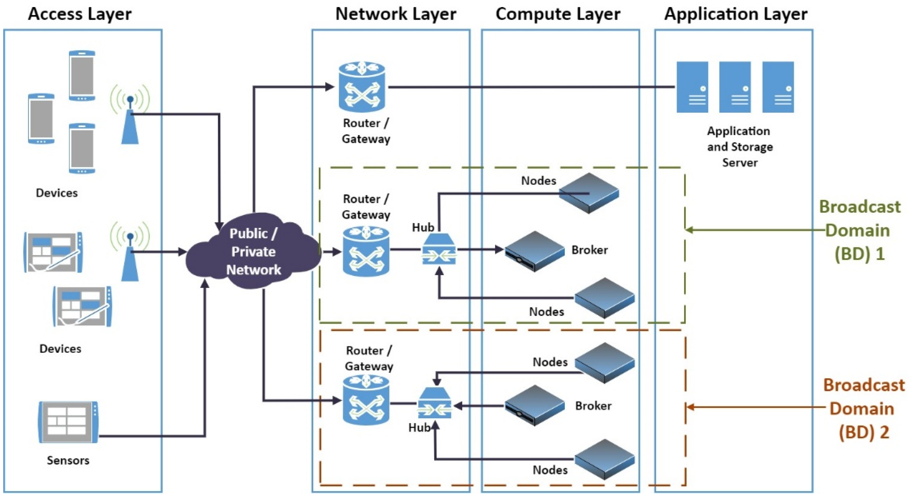
13], is very distinct. LMF uses a functioned based layer to categorize each of its segments. First is the access layer, then the network layer and the computational layer and last is the application layer. The four layers of LMF are portrayed in
Figure 2 [
14].
The lowest layer, which consists of IoT devices and sensors, is the access layer. This layer can be connected to the public Internet or a private local network. Therefore, the implementation of LMF could be on public or private networks.
The layer that performs network functions contains routers and switches are the network layer. Network devices in the network layer served as a gate. It sends data to the blockchain brokers and blockchain nodes. The network layer provides one gateway for each broadcast domain. The network layer has at least one routing network devices for each broadcast domain, which accommodates one broker and several nodes. Each broadcast domain can also be symbolized as a town, territorial, region or state. Therefore, the number of broadcast domains is equivalent to the number of towns, territorials, regions or states where the technologies is applied.
The computational resources populate the computational layer, which has one broker and a certain number of blockchain nodes in each broadcast domain. Originally, the node simply handles the transactions from the broker on the same broadcast domain. If the broker is not available, then the node that has certain resources in the same broadcast domain will become a new broker. If there are no existent nodes with certain computational resources in a specific broadcast domain, the broker in the other broadcast domain will become the new broker for the specific broadcast domain.
The top layer in LMF is the application layer, which contains several application servers and database servers. The backup nodes also reside in this layer. The application servers stored and processed transactions and data in this layer.
2.1. Broadcast Domain on LMF
The Broadcast Domain (BD) is an area or group that contains nodes that will reply to all broadcast packets from every node within the same region or group. The Broadcast Domain in the LMF is applied to isolate each region. The regions can represent territorials, towns or states. This platform is adopted to mitigate large-scale DDoS attacks on node brokers. After a DDoS attack has occurred against one or multiple brokers on one broadcast domain, the attack will not influence the brokers on other broadcast domains [
14].
Every broadcast domain has a node that acts as a broker. Another node act as a computational layer. None of these nodes communicate with distinct broadcast domain nodes, except when the broker goes down, but no node on a specific broadcast domain can serve as a broker [
14].
The data mechanism on LMF is similar to LSB. The whole nodes in the broadcast domain have their independent Public Keys (PK). Each node would issue a unique public key for each transaction. Each block included the applicant’s public key hash, the destination’s public key hash for this specific transaction and the applicant’s public key hash for the upcoming transaction [
13]. This mechanism ensures that subsequent transactions are legal. This is done by comparing the applicant’s public keys in subsequent transactions with the applicant’s public keys that have been saved in previous transactions. Brokers also communicate with all the network’s other brokers on a distinct broadcast domain. This communication authorizes transactions using indirect and direct evidentiary mechanisms [
13]. This mechanism will lessen the time for verification.
Distant from LSB, LMF saves blocks in the local nodes on the broadcast domain. Arriving transactions to the broadcast domain will not be kept in the distinct node on a distinct broadcast domain. Each broadcast domain could possess a distinct blockchain because each broadcast domain has its distinct blockchain and its backup nodes in the cloud. Therefore, when all nodes on the broadcast domain are not available, the block is still kept in the backup node on the cloud. There was a distinction between cloud and local nodes, i.e., each node could have only one broker in a specific broadcast domain. Yet, the cloud node is a member for every broker on all broadcast domains because it acts as a backup node.
The status, availability, capacity of All nodes, brokers and cloud nodes are checked regularly by the Central Monitoring and Provisioning Application on the Cloud/Application Layer. This Monitoring and Provisioning Application is also the one that pushes the configuration files on all nodes, brokers and cloud nodes. When a broker in the specific broadcast domain is not available, the Application will push a new configuration to the nodes containing new Broker information. This mechanism is presented in
Figure 3.
The Application Server serves as a Monitoring tool, which monitors the availability status and capacity status on each broker and each node on all Broadcast Domains (M1). The application server also serves as a Provisioning tool, which pushes configuration files to each broker and each node on all Broadcast Domain (M3). The configuration file tells the node about its broker and Broadcast Domain information. When a broker in the specific broadcast domain is not available, the Application will push a new configuration to the nodes containing new broker information (M6). If the new broker is on a different Broadcast Domain, then the new configuration will include the new Broadcast Domain for the nodes. All nodes and brokers also send information about their status to the application when there is an error or low capacity (M2). As for the broker, the configuration file will also include the neighbor relationship between a broker in different Broadcast Domains (M5).
By default, brokers in different Broadcast Domains cannot communicate with each other without this neighbor table information. Neighbor table information is used by the broker to communicate with each other for authorizing the transactions using indirect and direct evidentiary mechanisms. Other than broker-to-broker communication for authorizing the transactions, no other transaction between a node to other node on different Broadcast Domain. As for Cloud Nodes, Cloud Nodes also have their independent Public Key (PK), similar to local nodes. Each transaction block will include the applicant’s public key hash, the destination’s public key hash for this specific transaction and the applicant’s public key hash for the upcoming transaction [
13]. The broker will verify this transaction using direct or indirect evidence to another broker. When there is no evidence before, the broker will verify and validate it first and then broadcast this transaction, which will be signed by all nodes in a specific Broadcast Domain. However, if there is evidence before, this transaction has already been verified, and the broker will not need to validate it again.
The Broadcast Domain on the Lightweight Multi-Fog blockchain (LMF) has its ledger or chain separate from each other, except for Cloud nodes. Normally, only brokers on the same Broadcast Domain could be accessed. It stores data on the node with the same Broadcast domain. However, if there are attacks on one Broadcast Domain, other brokers on different Broadcast Domains can become brokers of a failed Broadcast Domain, with Cloud nodes as its node.
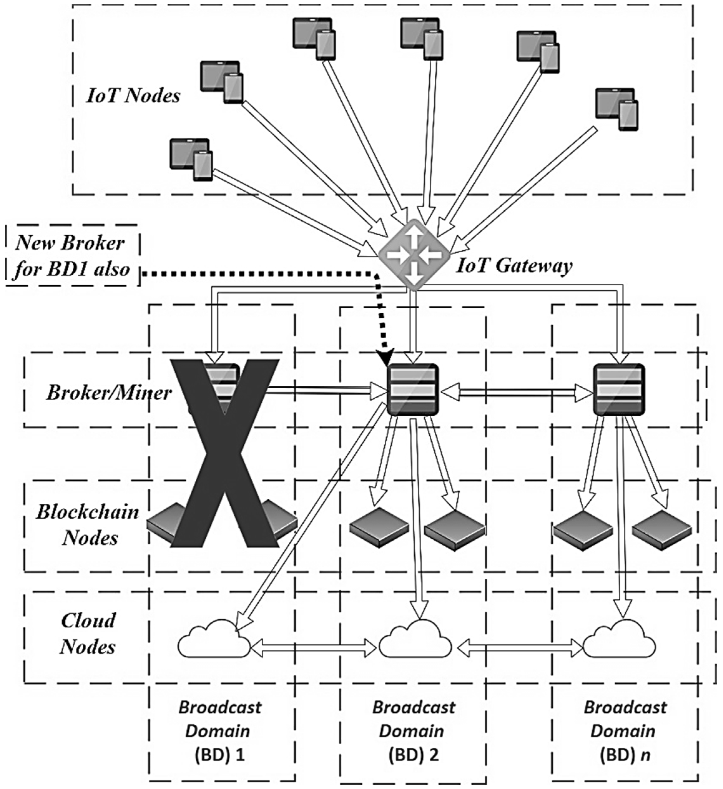
Figure 4 shows the flow when the broker is down or has failed. Other nodes can become the new broker for the failed Broadcast Domain; for example, Broadcast Domain 1 (BD1). As long as there is an available node on the failed Broadcast Domain that can become a new broker, no broker is selected outside of the failed Broadcast Domain. The application selects the node with the highest available compute resources and the lowest latency to the Applications and the other brokers.
The Broker outside can be selected if all nodes on the failed Broadcast Domain are down or when there are attacks on a failed Broadcast Domain. A Failed Broadcast Domain is discovered by the Application when the Application is unable to communicate with the broker and all nodes in a particular Broadcast Domain. The application will mark the Broadcast Domain as failed if it cannot communicate with the broker and all nodes in it. The new Broker will have the blockchain for the failed Broadcast Domain because it has Cloud Nodes which are members of all Broadcast Domains.
Figure 5 shows that the Broker on Broadcast Domain 2 (BD2) becomes the new broker for Broadcast Domain 1 (BD1), which failed due to attacks. The broker from Broadcast Domain 2 (BD2) becomes the new broker and will have the database from Broadcast Domain 1 (BD1), because it has Cloud nodes that are a member of all Broadcast Domains. The Cloud Node on Broadcast Domain 1 (BD1) and Broadcast Domain 2 (BD2) are one entity with two or more nodes in the same cluster. The Application will select a broker from Broadcast Domain nearest to the IoT nodes or users to become the new broker for the failed Broadcast Domain.
2.2. LMF’s Broadcast Domain LMF Simulation Using LMFSIM
In these papers, we compared the performance of the Lightweight Multi-Fog blockchain (LMF) topology model, where the broadcast domain is separated based on the location with the blockchain topology model of the Proof of Work (PoW) method on the LoRa network. In this research, a simulation of the IoT LMF network broadcast domain is made using the Simpy 3.0.11 program instrument. The program also simulated packet transmissions that pass through the network with several variables that varied to discover the transmission time needed and the amount of energy expended by the node.
This study uses LoRa to simulate sending a packet from a random node to the Base Station (BS), after which the packet is then sent to the broker for all nodes in the PoW method or in a Broadcast Domain (BD) in the LMF method. The broker will then conduct a mining process, which consists of identification, authentication, authorization and verification, to then be stored in a block and sent to all nodes that are on the same broadcast domain in the form of a blockchain.
Based on the modeling, the parameters to be measured are as follows:
The LMFSim simulator (
https://github.com/myanuararys/lmfsim, accessed on 10 March 2020) was used here, which is a combination of the LoRaSim simulator [
18] and the BlockSIM simulator [
19], which runs on the Linux operating system Xubuntu 18.04 LTS. LMFSim has not yet simulated full consensus on LMF of Broadcast Domain failover mechanism. It only simulates packet transmission on LoRa with multiple nodes or Broadcast Domain with a simple PoW and LMF Broadcast Domain model. The parameter settings in the LoRa simulation use the SN5 set type. SNn defines a LoRa configuration parameter set where the Spreading Factor (
SF), Transmission Power (
TP), Bandwidth (
BW) and Carrier Frequency (
CF) are set the same in all experiments [
18]. The number of packages sent at each trial was set to 20 bytes.
The simulation was run using 1 Base Station (BS) or gateway for all nodes on the LoRa network. A packet of 20 bytes is sent from one of the nodes chosen at random to the Base Station (BS). Then, the packet is sent from the Base Station (BS) to all broker nodes to be verified, validated and encrypted and then sent to all existing nodes (on PoW) or nodes that are in a Broadcast Domain (BD) with broker nodes (on LMF). The maximum latency between nodes () was set to 20 ms.
The simulation is performed by varying the number of nodes () and the number of broadcast domains (). The value of the Spreading Factor (SF), Transmission Power (TP), Bandwidth (BW) and Carrier Frequency (CF) on the SN5 set type are 12 MHz, 14 dBm, 125 MHz and 868 MHz, respectively. The number of broadcast domains () on LMF and the number of miner nodes () cannot be less than the number of nodes (). The number of broker nodes on LMF is the same as the number of broadcast domains (). This is because every broadcast domain has a requirement to have one node functioning as a broker (broker node).
Some libraries and programs are required before running LMFSim. The base program is python3, simpy, numpy, python-pip, network, pandas and matplotlib. All of these programs can be installed using the apt-get function on Xubuntu. The hardware and specifications of the computer used in this paper can be seen in
Table 1.
In the LMFSim simulator, there are two classes. The first is named myNode, which creates IoT nodes. The second is blocknodes, which defines the blockchain variables of compute nodes, such as miner and broker. This class also defines receiver functions to solve cryptographic puzzles (mining), broadcast transactions from broker to all nodes and accept transactions on each node. Apart from the main class, there are several functions. First is the node_generator function, which configures nodes according to consensus and the variables defined in the config file. There is also the trans_generator function, to perform transaction generation, and the monitor function to store generated blocks. Last is the transmit function, which sends packets from each node to the Base Station (BS). Example of simulation can be seen in
Figure 6.
4. Results and Analysis
We calculated the total transmission time () and total energy () obtained from each experiment with different variables to measure the performance.
4.1. LoRa IoT Network Work System with the PoW Blockchain Model
The total transmission time (
) is obtained from the first and second simulations. A comparison of the total transmission time and the number of nodes (
) can be seen in
Figure 8. A comparison of the total transmission time value and the number of miner nodes (
) can be seen in
Figure 9.
Figure 8 shows that the greater the number of nodes (
), the higher the total transmission time (
). It can be estimated that the time needed to process the mining and broadcasting of packages to all existing nodes increases with the number of nodes (
). This increase of the amount of time increases the total transmission time (
).
Figure 9 shows that the greater the number of miner nodes (
), the higher the total transmission time (
). Increasing the number of miner nodes (
) increases the number of nodes that conduct the mining. It also increases the time needed to send packets to all existing nodes. There is also a sudden increase of the total transmission time (
) in
Figure 9. This increase happens when the number of miner nodes (
) reaches 450. This sudden increase is caused by the increase of the number of collision and the number of transmissions. The increase of the number of nodes increases the number of collisions and the number of transmissions. The distance between the nodes also becomes one of the aspects that can increase the total transmission time (
). LMFSim used part of LoRaSim, which set the distance between the nodes randomly based on the Path Loss model [
18].
It can be concluded here that on the IoT network with the PoW blockchain model, an increase of the number of nodes (
) or the number of miner nodes (
) will increase the total transmission time (
), as shown in
Figure 8 and
Figure 9. Equation (3) can be used to measure the average increase of the total transmission time (
) with respect to the number of nodes (
) or the number of miner nodes (
):
Equation (3) shows that the average increase of the total transmission time per additional node is 0.72%. In addition, the average increase of the total transmission time per additional miner node is 0.9%. It can be concluded that increasing the number of miner nodes () increases the amount of time needed for transmission more than when increasing the number of nodes ().
We calculated the total amount of energy (
) obtained from the first and second simulations. A comparison of the total energy used for sending with respect to the number of nodes (
) can be seen in
Figure 10. In addition, a comparison of the total energy for transmission with respect to the number of miner nodes (
) can be seen in
Figure 11.
Figure 10 shows that the greater the number of nodes (
), the higher the total amount of energy (
). It can be estimated that the energy needed to process the mining and broadcasting of packets to all existing nodes increases with the number of nodes (
). The increase of the amount of energy is what increases the total energy used for packet/block transmission (
).
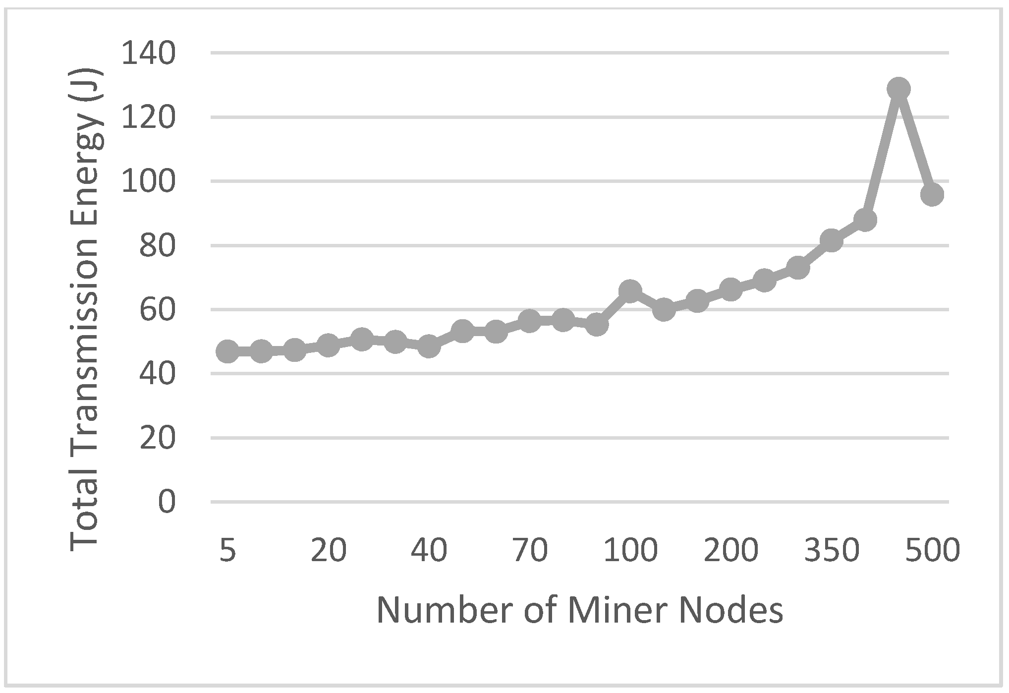
Figure 11 shows that the greater the number of miner nodes (
), the higher the total transmission energy (
). Increasing the number of miner nodes (
) increases the number of nodes that conduct the mining, thus increasing the energy needed to send packets to all existing nodes. The sudden increase of the total transmission energy (
) also happens in
Figure 11. This increase happens when the number of miner nodes (
) reaches 450. The reason of this sudden increase is the increase of the number of collisions and the number of transmissions. The increase of the number of nodes increases the number of collisions and the number of transmissions. The distance between the nodes is one of the aspects that can increase the total transmission energy (
). LMFSim used part of LoRaSim, which set the distance between nodes randomly based on the Path Loss model [
18]. A highest number of collision and transmission happens when the number of miner nodes (
) reaches 450.
It can be concluded that on the IoT network with the PoW blockchain model, an increase of the number of nodes (
) or the number of miner nodes (
) will increase the total transmission energy (
), as shown in
Figure 10 and
Figure 11. We use the following equation to measure the average increase of the total transmission energy (
) per node (
) or per miner node (
):
Equation (4) shows that the average increase of the total transmission energy per node is 1.68%. In addition, the average increase of the total transmission time per additional miner node is 0.31%. This is in contrast with the increase of the total transmission time. Therefore, increasing the number of miner nodes () results in a lower increase of the energy needed for transmission than when increasing the number of nodes ().
4.2. LoRa IoT Network Work System with LMF Blockchain Model
A comparison of the total transmission time to the number of nodes (
) can be seen in
Figure 12. In addition, a comparison of the total transmission time versus the number of broadcast domains (
) can be seen in
Figure 13.
Figure 12 shows that the greater the number of nodes (
), the higher the total transmission time (
). It can be estimated that the time needed to process the mining and broadcasting of packages to all existing nodes increases with the number of nodes (
). This increase of the amount of time increases the total transmission time (
). There is also a sudden increase of the total transmission time (
) in
Figure 12. This increase happens when the number of nodes (
) reaches 480. The reason of sudden increase caused by the increasing of the number of collisions and the number of transmissions, similar to
Figure 9. The increase of the number of nodes and distance between nodes increases the number of collisions and the number of transmissions. LMFSim used part of LoRaSim, which set the distance between node randomly based on the Path Loss model [
18]. Either using the PoW or LMF platform, the Path Loss model used in the LMFSim is the same.
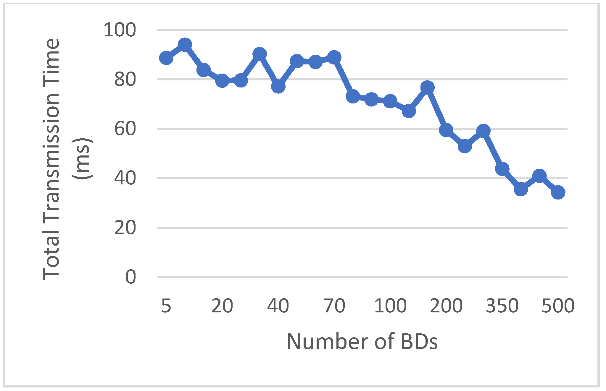
Figure 13 shows that the greater the number of broadcast domains (
), the smaller the total transmission time (
) when the number of broadcast domains (
) approaches the number of nodes (
). Increasing the number of broadcast domains (
) decreases the number of broadcast domains. This is because LMF does not broadcast on all the nodes, but rather only on the nodes that have the same broadcast domain. When the number of broadcast domains (
) gets closer to the number of nodes (
), the broadcasting process decreases. The transmission time also decreases.
It can be concluded that on the IoT network with the LMF blockchain model, an increase of the number of nodes (
) will increase the total transmission time (
), as shown in
Figure 12. The total transmission time (
) decreases when the number of broadcast domains (
) approaches the number of nodes (
), as in
Figure 13. Equation (3) is used to measure the average increase of the total transmission time (
) with respect to the number of nodes (
) or the number of broadcast domains (
).
From Equation (3), the average increase of the total transmission time per node is 0.53%. In addition, the average increase of the total transmission time per additional broadcast domain is 0.27%. It can be concluded that the increase of the number of broadcast domains () shortened the time needed for sending compared to increasing the number of nodes ().
Furthermore, we calculate the total transmission energy (
) obtained from the first and second simulations. A comparison of the total transmission energy and the number of nodes (
) can be seen in
Figure 14. A comparison of the total transmission energy and the number of broadcast domains (
) can be seen in
Figure 15.
Figure 14 shows that the greater the number of nodes (
), the higher the total transmission energy (
). The energy needed to process the mining and broadcasting of packets to all existing nodes increases with the number of nodes (
). The increase of the amount of energy is what increases the total transmission energy (
). The sudden increase of the total transmission energy (
) also happens in
Figure 14. This increase happens when the number of nodes (
) reaches 480. The reason of this sudden increase is the increase of the number of collisions and the number of transmissions. The increase of the number of collisions and the number of transmissions caused by the random distance between nodes. LMFSim used part of LoRaSim, which set the distance between the nodes randomly based on the Path Loss model [
18]. The highest number of collision and transmission happens when the number of miner nodes (
N_miner) reaches 480.
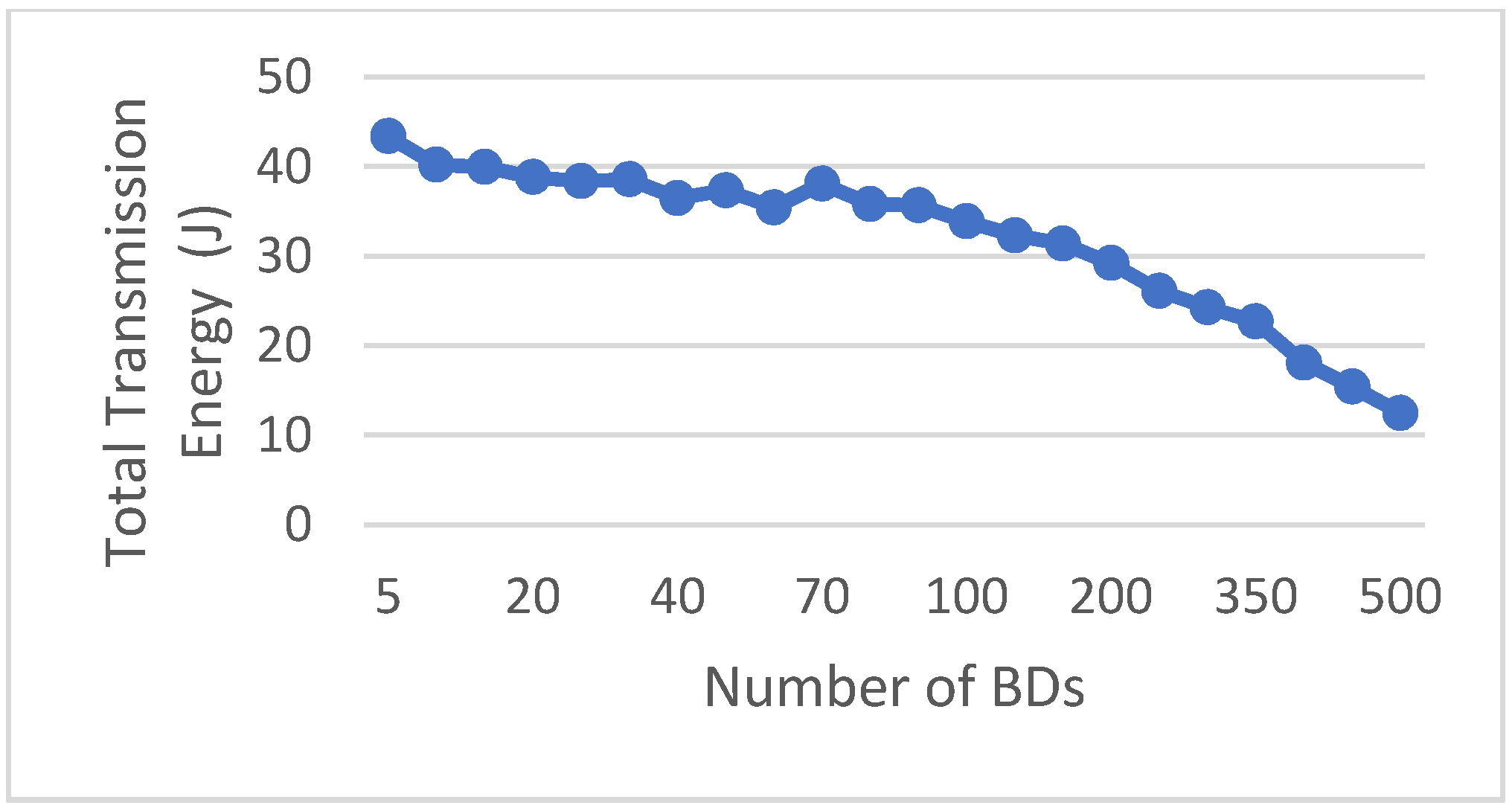
Figure 15 shows that the greater the number of broadcast domains (
), the smaller the total energy transmission (
) when the number of broadcast domains (
) approaches the number of nodes (
). Increasing the number of broadcast domains (
) decreases the number of broadcasts. This is because LMF does not broadcast on all nodes but only on the nodes that have the same broadcast domain. When the number of broadcast domains (
) approaches the number of nodes (
), the duration of the broadcasting process decreases. Therefore, the amount of energy needed also decreases.
It can be concluded that on the IoT network with the LMF blockchain model, an increase of the number of nodes (
) will increase the total transmission energy (
), as shown in
Figure 14. The decreasing total transmission energy (
) when the number of broadcast domains (
) approaches the number of nodes (
) is shown in
Figure 15. Equation (4) can be used to measure the average increase of the total transmission energy (
) with respect to the number of nodes (
) or the number of broadcast domains (
).
From Equation (4), the average increase of the total transmission energy per node is 1.73%. Moreover, the average increase of the total transmission energy per additional Broadcast Domain is 0.28%. It can be concluded that the increase of the number of broadcast domains () makes the amount of energy needed for transmission smaller than that when the number of nodes () increases.
4.3. Comparison of the PoW and LMF Models on the LoRa IoT Networks
From the simulation, we get the total transmission time (
) and the total amount of energy (
) for each model. Using these values, we can compare the two blockchain models. The total transmission time (
) is obtained from the first and second simulations. A comparison of the total transmission time and the number of nodes (
) in the PoW and LMF models can be seen in
Figure 16. In addition, a comparison of the total transmission time and the number of broadcast domains (
) or the number of miner nodes (
) can be seen in
Figure 17.
Figure 16 shows that the greater the number of nodes (
), the higher the total transmission time (
). The increase of the total transmission time (
) for the PoW and LMF models is almost the same. When compared to the average increase of the average total transmission time (
) based on Equation (3), the LMF model has a smaller value (
), namely, 0.53%. LMF is more scalable than PoW. When there is an attack on a node, the attack cannot impact a node in another broadcast domain. PoW has only one broadcast domain; therefore, when an attack comes, it will impact all nodes in the system.
Figure 17 shows a clear difference between the PoW and LMF models. The higher the number of broadcast domains (
), the smaller the total transmission time (
). The greater the number of miner nodes (
), the higher the total transmission time (
). When compared to the average increase of the average total transmission time (
) based on Equation (3), the LMF model has a smaller increase of its average total transmission time (
), namely, 0.27%.
It can be concluded that the IoT network with the LMF blockchain model has a smaller impact on the increase of the total transmission time (). This is calculated based on a comparison of the increase of the average total transmission time ().
Furthermore, the total transmission energy (
) is obtained from the first and second simulations. The comparison of the total transmission energy to the number of nodes (
) in the PoW and LMF models can be seen in
Figure 18. The comparison of the total transmission energy to the number of broadcast domains (
) or the number of miner nodes (
) can be seen in
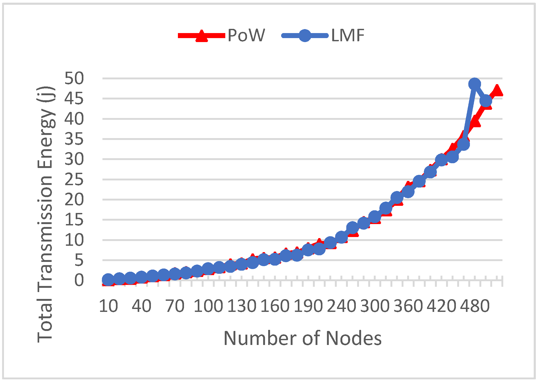
Figure 19.
Figure 18 shows that the greater the number of nodes (
), the higher the total transmission energy (
). The increase of the total energy delivered (
) between the PoW and LMF models is almost the same. Compared to the increase of the average transmission energy (
) based on Equation (4), the PoW model has a smaller value (
), namely, 1.68%.
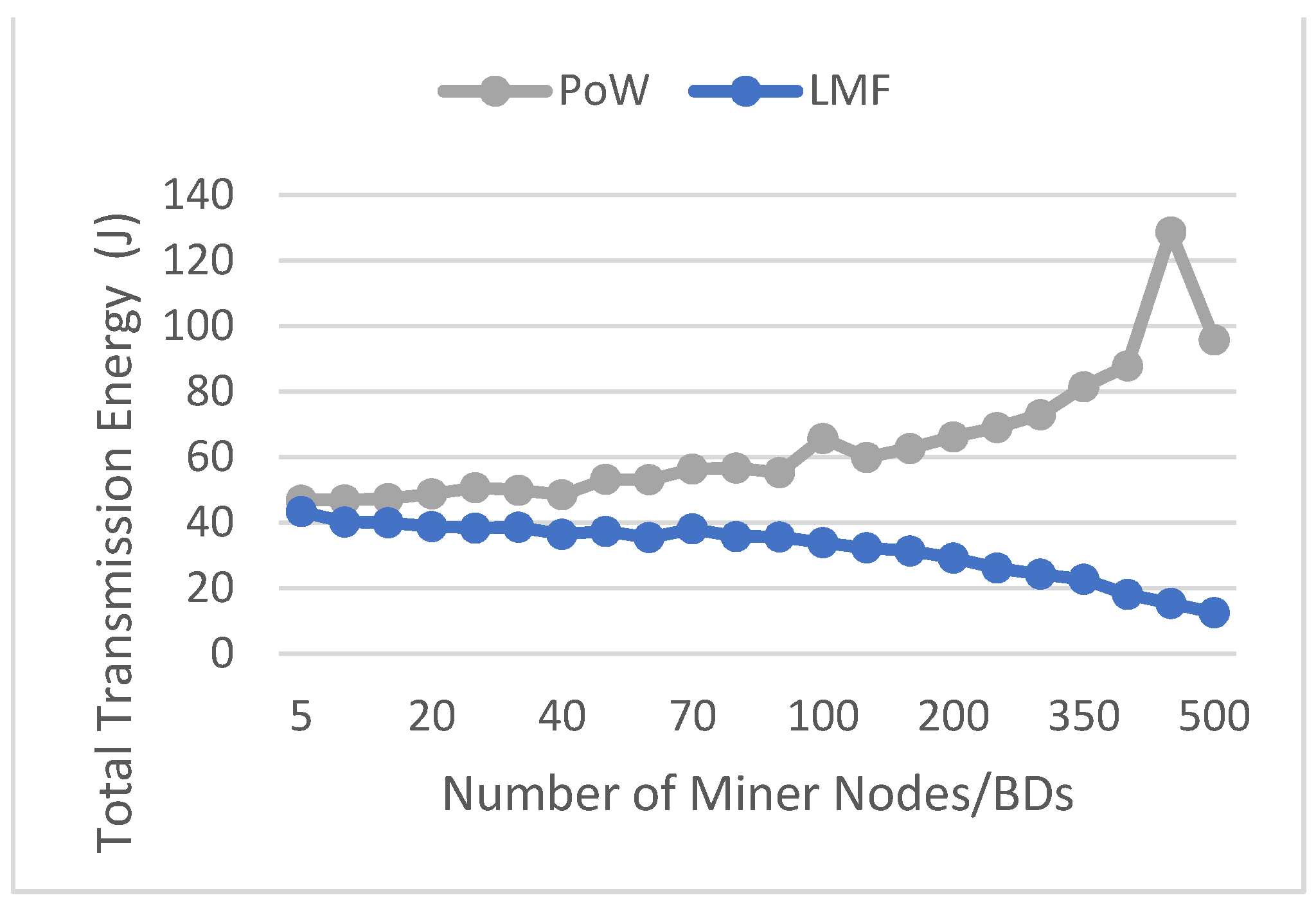
Figure 19 shows a clear difference between the PoW and LMF models. The greater the number of broadcast domains (
), the smaller the total transmission energy (
). When the number of miner nodes (
) is greater, the total transmission energy (∑E) will be even greater. When compared to the average increase of the average total transmission energy (
) based on Equation (4), the LMF model has a smaller increase of the average of total transmission energy (
), namely, 0.28%.
It can be concluded that the IoT network with the LMF blockchain model has a smaller impact on the increase of the total transmission energy () based on the increase of the total average transmission energy () if the number of broadcast domains () increases. The IoT network with the PoW blockchain model has a smaller impact on the increase of the total transmission energy () based on the average increase of the total transmission energy () if the number of nodes () increases.
Although LMF itself has the advantage of lower latency and energy, it makes the blockchain not as strong as the blockchain on the PoW platform. This is because each broadcast domain node has its own blockchain, which is not owned by another node on a different broadcast domain. To overcome this, two or more broadcast domains can be used to increase the availability if one broadcast domain dies or if a node in the cloud becomes a node or member of each broadcast domain.
4.4. Future Works
As mentioned before, this paper simulated only how the broadcast domain works on the LMF platform and the advantage of separating the broadcast domain from its own fog topology, but it did not simulate the entirety of the LMF platform or consensus. We also have yet to simulate and implement the LMF platform as a prototype in its entirety. We have not tested the encryption mechanism and how to keep all nodes synced in near-real time. The encryption mechanism could be improved upon in the future, for example by combining Software and Hardware certifications as part of Trusted Computing technology [
20].
Backup mechanisms for the cloud, proposed in our previous paper [
14] and reexplained in detail on
Section 2.1, will become the key to keeping nodes and brokers in sync, and ensure that they can take over another broadcast domain when one or some broadcast domains fails/are attacked. The cloud can become another broker who will be a member of every broadcast domain. If one broadcast domain is unavailable, another broker on a different broadcast domain can take over the process with the cloud as its node member, who has backup data from an unavailable node in the failed broadcast domain [
13].
The Monitoring and Provisioning Application will be the center to monitor and provision brokers and nodes in Broadcast Domain/Fog Networks and Cloud Nodes, so it still has some security challenges. A performance-oriented Monitoring System can be one of the solutions in the future for Applications to manage, monitor and provide brokers and nodes more securely [
21]. By using a Performance Oriented Monitoring System, the Application can monitor the availability, security and capacity of all brokers and nodes safely. The application itself can be strengthened with triple-layered monitoring [
22] and Dynamic Security Monitoring as part of a PASSIVE infrastructure [
23].
In this paper, we did not discuss the end devices or user devices at the Access Layer in detail. In the future, we will need to consider exploring the possibilities of end-to-end simulation, implementation and security. TPM-based protection can be used to secure end devices with the SecMiLiA library [
24] and auto-configurable environment [
25].
We also have not yet analyzed the advantage of broadcast domain separation in a country that has a data localization policy. Some countries, such as Indonesia, have a data localization policy which states that data are prohibited from being saved outside the territory of Indonesia [
26]. We also have not yet compared this method with another lightweight blockchain platform, such as LSB [
13] and FogBus [
12]; this will be the focus of one of our future works.
6. Conclusions
In this research, a simulator has been successfully designed and used to conduct experiments and evaluations of the action mechanism of broadcast domains on the IoT LoRa network with LMF and PoW blockchain models.
The comparisons of the increase of total transmission time () and total transmission energy () on the PoW and LMF models show that the results are almost the same when the number of nodes is increased (). Regarding the LMF, the average increase of the total transmission time (), which is 0.53%, is smaller and the total transmission energy (), which is 1.73%, is higher than those of PoW. When there is an increase of the number of miner nodes () or the number of broadcast domains (), the average increase of the total transmission time (), which is 0.27%, is smaller and the total transmission energy (), which is 0.286, is smaller than those of PoW.
Although LMF has the advantage of less latency and energy, this makes the LMF blockchain weaker than the PoW platform. This is because each broadcast domain node has its own blockchain. To overcome this, two or more broadcast domains can be used to increase the availability.
The application of the blockchain on the IoT network can continue to be developed to get the best model or platform from the blockchain, which can increase the security of the IoT network without increasing the latency and required computing resources. LMF itself with its broadcast domain can still be developed further so that it can decrease the latency and computing resources of the IoT network. The LMF model blockchain simulation also needs to be further developed using a modeling consensus, not just the broadcast domain mechanism, so that the results will be closer to reality before the model can be applied to the real world.


