1. Introduction
Transportation electrification is an important solution for environmental degradation and non-renewable energy shortage problems. Various electric vehicle configurations have been proposed in academia and industry. At the moment, most of the electric vehicles on the market such as Tesla, Mercedez-Benz EQC, Nissan Leaf and BMW i3 are equipped with single gear transmissions owing to the large speed range and low-speed high-torque characteristics of electric motors [
1,
2]. Some electric vehicles use two motors on the front axle and rear axle respectively to further improve the vehicle dynamic performance [
3]. The multi-gear and multi-motor powertrains are widely researched in academia with the motivation of improving the electric vehicle energy economy and dynamic performance. The automated manual transmission (AMT) [
4,
5], dual clutch transmission (DCT) [
6], automatic transmission (AT) [
7,
8] and continuous variable transmission (CVT) [
9,
10] have been implemented in electric vehicles.
The in-wheel drive electric vehicles (IEV) in which electric motors are directly connected to wheels have been considered as one of the most important formats of electric vehicles [
11]. The IEV could eliminate all of the driveline components so that the transmission power loss is cancelled. The vehicle handling and stability performance are significantly improved by the torque vector control based on the quick torque response and outstanding controllability of electric motors [
12,
13]. In addition to the attractive advantages of IEV, there are also some unsolved problems which hinder its implementation. Limited installation space makes it difficult for heat dissipation [
14]. The vibration caused by increased unsprung mass reduces the vehicle drive comfort and deteriorates the suspension and motor bearing working conditions, which accelerates the components’ fatigue and failure [
15].
Compared with the electric motor, the hydraulic motor has a higher power density, which means less unsprung mass will be added if the hydraulic motor is used for in-wheel drive [
16,
17]. So the vibration problems caused by increased unsprung mass could be mitigated. Besides, the hydraulic motor is driven by fluids, which naturally constitute the cooling system. The wheels have to work under complex environments like in water or off road, which proposes challenges for the high voltage electrical system. In contrast, the hydraulic system is more reliable in these complex working conditions. These advantages make the hydraulic motor a potential candidate for in-wheel drive [
18]. The hydraulic motor has been used for vehicle driving in massive researches combined with electric motors. The parallel electric hydraulic hybrid vehicle [
19,
20,
21] and series electric hydraulic hybrid vehicle [
22] have been widely investigated. These vehicles take the advantage of the high power density of hydraulic motors to recover more braking energy so that the vehicle energy economy is improved. The hydraulic motor has also been used for in-wheel drive [
16]. However, in this proposal, the engine is used to generate the hydraulic power so it still relies on traditional fossil fuel.
With the motivation of exploiting the merits of in-wheel drive and electrification, an in-wheel drive electric hydraulic hybrid vehicle (IHV) is investigated in this paper where the hydraulic motor is used for in-wheel drive and an electric motor is used as the power source. The energy economy and vertical vibration characteristics of the IHV are compared with the IEV and a centralized drive electric vehicle (CEV). The dynamic programming (DP) algorithm is adopted in the energy management strategy design, which helps to find the optimal energy economy of each vehicle. Due to the vehicle vertical vibration having a significant impact on the vehicle driving comfort, the vertical characteristics of each vehicle are compared based on a quarter car model.
The remainder of this paper is presented as follows:
Section 2 introduces the vehicle powertrain configurations and working principles of each vehicle. In
Section 3, the dynamic models of vehicle powertrains are built.
Section 4 designs the energy management strategies based on dynamic programming. In
Section 5, simulations are conducted to analyze the energy consumption of each vehicle.
Section 6 analyses the vertical vibration characteristics of each vehicle. In
Section 7, conclusions are drawn for this paper.
2. Vehicle Powertrain Configurations and Working Principles
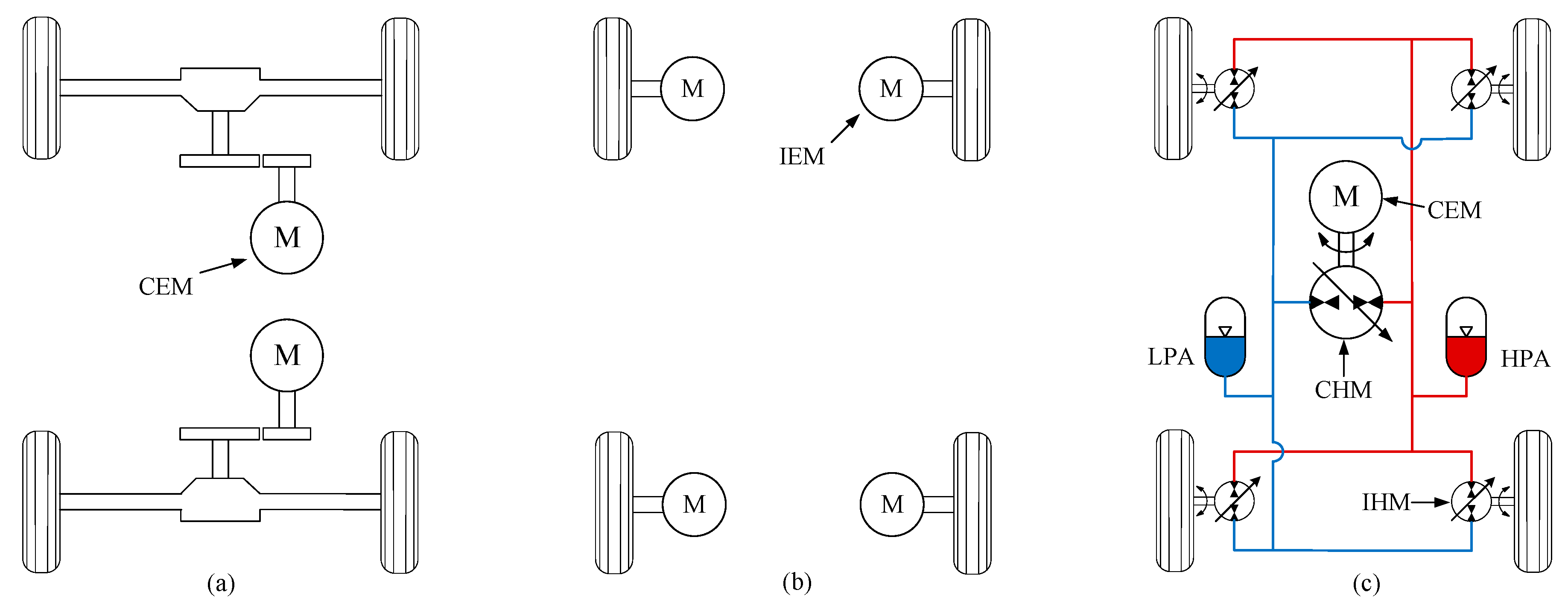
The configurations of CEV, IEV and IHV are shown in
Figure 1. In the CEV, two central electric motors (CEM) are installed on the front axle and rear axle, respectively. Single speed transmissions are used to adjust the CEM speed and torque to coordinate with the vehicle maximum speed and dynamic performance demand.
In IEV, the in-wheel electric motors (IEM) are used to drive the vehicle. In this research, an IEM produced by Protean electric is used for analysis. The IEM parameters such as speed, torque and power are specifically designed for in-wheel drive so it can be directly installed in wheel without any additional gears for speed and torque adjustment.
In IHV, in-wheel hydraulic motors (IHM) are installed in wheel to drive the vehicle. At the moment, there is no hydraulic motor designed for in-wheel drive. However, considering the vehicle wheel speed and torque demand during driving, the dual functional axial piston hydraulic motor is a suitable candidate for in-wheel drive owning to its high power density and high speed advantages. The high pressure accumulator (HPA) is used to store energy and the low pressure accumulator (LPA) is used as an oil tank. During driving, the IHM works as a motor and the oil flows from the HPA to the LPA. During regenerative braking, the IHM works as a pump and the oil flows from the LPA to the HPA. In addition to regenerative braking, the HPA could also be charged by the central hydraulic motor (CHM). In this charging condition, the CEM drives the CHM to charge the HPA. The HPA can also be used to charge the battery through the CHM and CEM.
3. Modelling of the Vehicle Powertrains
3.1. Electric Motor Model
The electromagnetic response of power electronics presents a higher frequency than that of mechanical driveline so the frequency oscillations from the power electronics systems can be overlooked to improve the computation efficiency and simplify the control problem [
23]. The maximum electric motor torque is modelled as a lookup table regarding the motor speed. The real-time electric motor torque output
according to the driver’s command can be expressed as:
where
is the accelerator pedal opening and
is the tested maximum electric motor torque at speed
.
3.2. Battery Modelling
The battery parameters are affected by many factors like temperature, state of charge (SoC) and charging rate. An accurate dynamic model is difficult to build and would be very complicated. Therefore, in this paper, the battery is modelled as a simplified internal resistance model [
24,
25]. Those battery parameters which could truly reflect the battery characteristics were obtained from the test. Based on the model, the SoC change rate is described by Equation (2).
where
is the open circuit voltage,
is the battery internal resistance,
is the maximum capacity and
is the battery power which is calculated by Equation (3).
where
is the electric motor efficiency, which is modelled as a 2-D lookup table regarding to the output torque and speed.
The
and
, along with SoC, are shown in
Figure 2. In this model, the battery characteristics are calibrated with 25 °C temperature.
3.3. Hydraulic Motor Modelling
The hydraulic motor torque is generated by the pressure difference between HPA and LPA. By adjusting the swashplate angle, both positive and negative torques are available for vehicle driving and braking. The hydraulic motor torque is described by the following equation:
where
d is the hydraulic motor cylinder diameter,
is the number of the hydraulic motor cylinders,
R is the cylinder pitch radius [
26,
27],
is the hydraulic motor working pressure.
is the hydraulic motor mechanical efficiency, which is mainly affected by the working pressure, speed and displacement.
3.4. Accumulator Modelling
The accumulator stores energy by compressing the inert gas. In this model, the compression and expansion process is considered as an adiabatic process [
28]. So the energy loss due to heat exchange with the environment is neglected as it is much less than the energy transferred in the charging and discharging process. Compared with the inert gas, the oil compressibility is much lower and is therefore ignored in this model [
29].
The energy stored in the accumulator is described by:
where
E is the accumulator stored energy,
is the accumulator pre-charged pressure,
is the inert gas volume under the pressure
,
k is the gas ploy index and
P is the accumulator working pressure.
3.5. Vehicle Resistance Model
The vehicle resistance mainly consists of rolling resistance, aerodynamic drag resistance and road slope resistance. The total vehicle resistant torque is derived as:
where
g is the gravitational acceleration,
is the road slope,
is the air density,
is the vehicle frontal area,
is the air drag coefficient,
V is the vehicle speed,
is the rolling resistance coefficient,
is the tyre radius.
4. Energy Management Strategy Design Based on Dynamic Programming
The DP is a widely used optimization method for vehicle energy consumption analysis [
30,
31,
32]. In this paper, the DP is adopted to explore the optimal energy economy of each vehicle so that the comparison is more convincing. Firstly, the driving cycle is divided into
N points. At each point of 0, 1, 2,……,
N − 1,
N, the vehicle speed and acceleration is determined by the driving cycle so the power demand is calculated. Besides, at each point, state variables are chosen to describe the concerned targets. In the CEV and IEV, the state variable is the battery SoC, which directly reflects the energy consumption of each vehicle. In the IHV, the state variables are the battery SoC and the HPA pressure. The HPA pressure of IHV determines how much driving torque is available.
How the state variables transfer from the current point to next point is determined by the control inputs in the current point:
X is the state variables.
U is the control input. With different control inputs, the energy consumption is different. In CEV, the control inputs are the front CEM torque and the rear CEM torque. In the IEV, four IEMs are adopted, so there are potentially four control inputs. However, the driving torque is normally allocated to the left wheels and right wheels evenly to reduce control complexity [
33,
34]. Only when there are stability control or steering control requirements are all four IEMs independently controlled to generate a yaw moment for vehicle lateral dynamic control. In IHV, the front IHM torque, rear IHM torque, and CHM torque and speed are selected as the control inputs.
The DP calculates the energy consumption reversely from the
Nth point to the 0th point. For point
N to
N − 1, it calculates all the possible control inputs and finds the minimum energy consumption
from point
N − 1 to
N:
where
is the instantaneous energy consumption determined by
X and
U. Then the calculation keeps going recursively from
N − 1 and the minimum energy consumption
from the point
n to point
N is obtained:
When the calculation reaches the point 0, the minimum energy consumption
J for the whole driving cycle is obtained accompanied by the optimal control inputs sequence:
There are boundary conditions for the state variables and control inputs which should be satisfied during the whole process. These boundary conditions are caused by the components’ physical characteristics.
In CEV, the control inputs are the front CEM torque
and the rear CEM torque
:
The CEM torque is restricted between the minimum and maximum torque:
In IEV, there are four IEMs. However, the driving torque is only allocated between the front wheels and the rear wheels. The left wheels and the right wheels are with the same torque. Therefore, the control inputs are the front IEM torque
and rear IEM torque
:
The IEM torque is restricted between the minimum and maximum torque:
In IHV, the driving torque demand is allocated to the front wheels and the rear wheels. Similar to the IEV, the driving torque is evenly allocated between the left wheels and the right wheels. Besides, the CEM and CHM are used to transfer energy between the battery and HPA. The CEM and CHM are decoupled from the wheels so that their speeds and torques could be optimized to achieve the best energy economy. The control inputs in the IHV are selected as the front IHM torque
, rear IHM torque
, CHM torque
and speed
:
In IHV, the hydraulic motor swashplate angle could only be adjusted between its minimum and maximum limits, so they have limited output torques. The CHM speed
and CEM speed
are restricted by their speed limits. The HPA pressure
should also be maintained between its maximum and minimum values. The boundary conditions in IHV are:
5. Energy Consumption Simulation Analysis
The vehicle simulation models are built with Matlab to investigate their energy consumption. In this research, a production SUV with CEV configuration is selected as the benchmark vehicle. Its vehicle parameters are shown in
Table 1. The energy consumption research is based on the world harmonized light-duty vehicle test procedure class 3 (WLTP-3). It combines urban and high speed driving conditions, which are widely used to investigate the energy consumption of hybrid vehicles and electric vehicles. The WLTP-3 profile is shown in
Figure 3.
5.1. Energy Consumption of CEV
The front CEM and rear CEM working points are shown in
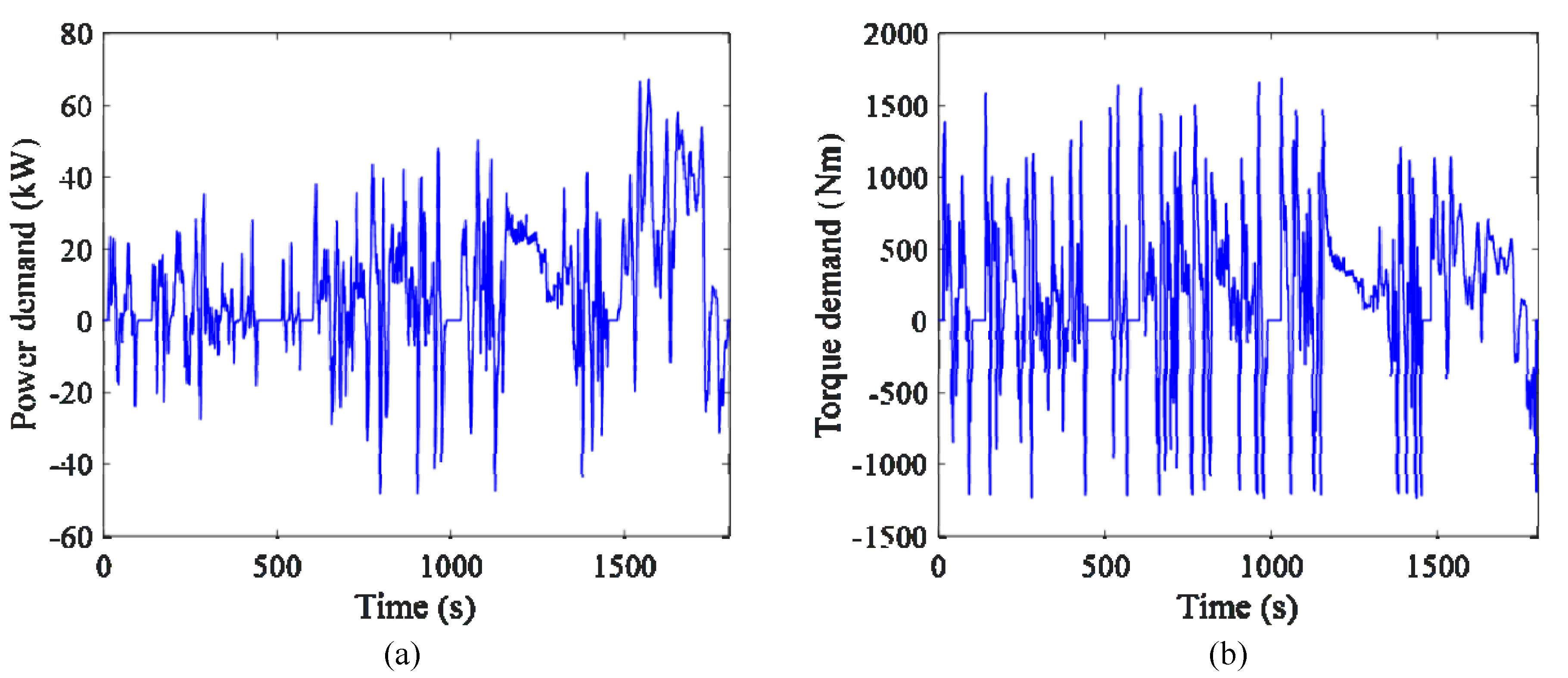
Figure 4. Most of the time it could be found that only rear CEM is used to drive the vehicle. This indicates that the CEV driving system is much oversized for normal driving conditions. The vehicle power demand and torque demand during the WLTP-3 are shown in
Figure 5. It is demonstrated that the power demand is much less than the equipped motor power. However, the large motor improves the vehicle dynamic performance during accelerating and climbing.
5.2. Energy Consumption of IEV
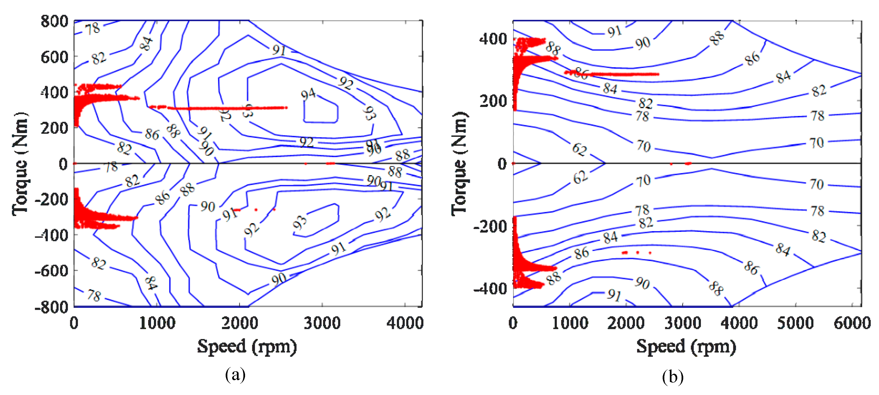
There are not any IEVs on the market at the moment. However, the PD18 IEM designed by protean electric has been produced and promoted to the market. This IEM targets in-wheel drive passenger vehicles. Therefore, it is selected to drive as the benchmark vehicle to investigate the IEV energy consumption. With four IEMs, the IEV driving system power is similar to the CEV. The IEM parameters are shown in
Table 2 and its efficiency map is shown in
Figure 6. The IEM is designed for in-wheel drive, so it is installed on the wheel directly without any additional gears.
By simulation, the IEM working points during WLTP-3 are shown in
Figure 6. It is shown that the rear IEM covers most of the driving torque, which means the powertrain is also oversized in IEV. Compared with CEV, the driving torque is allocated more to the front wheels.
5.3. Energy Consumption of IHV
The IHV is a novel vehicle configuration proposed in this paper, so the powertrain parameters need to be designed here. To make sure the IHV has similar vehicle dynamic performance with the CEV and IEV, the IHM power is selected to be close to the IEM. In IHV, a reduction gear is adopted to adjust the IHM speed and torque. The CHM and CEM are disconnected with the wheels, so they just need to satisfy the vehicle power demand but not the torque demand. From
Figure 5, the vehicle power demand is moderate while the torque demand is high. Therefore, only one CEM is reserved in the IHV powertrain. The CHM is selected as being of a similar power to the CEM. The parameters of the IHV are listed in
Table 3.
The IHM working points during WLTP-3 are shown in
Figure 7. It is shown that the IHVs also try to use only rear IHM for driving. It could also be found that the rear IHM working points distribution are different from the rear IEM. This is determined by the different efficiency maps of IHM and IEM.
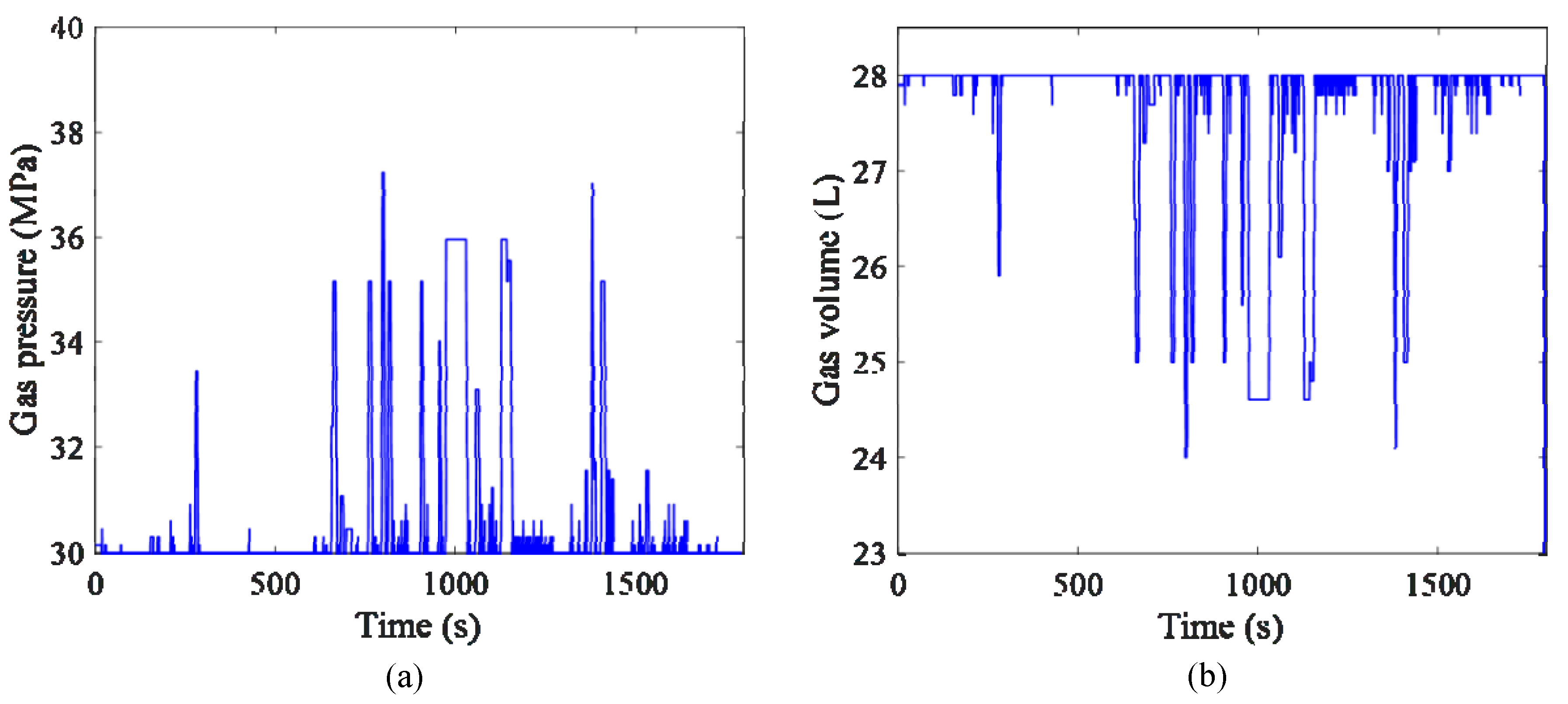
The HPA inert gas real time pressure and volume are shown in
Figure 8. It is shown that HPA pressure is always lower than its maximum working pressure. When the HPA is used for regenerative braking, the battery charging burden is relieved.
The CEM and CHM working points are shown in
Figure 9. As mentioned before, in IHV, the CEM and CHM are disconnected from the wheels. Therefore, under a certain power demand, the CEM and CHM could work at the most efficient point.
5.4. Energy Consumption Comparison
The energy consumption and SoC of each vehicle is shown in
Figure 10 and listed in
Table 4. It could be found that the IEV consumes slightly more energy than the CEV. The main reason is that the IEM has lower efficiency than the CEM, especially at a low speed area. These results indicate that although the driveline is simplified in IEV, which helps reduce power loss, the lower IEM efficiency makes the IEV not very competitive on the energy economy. However, as mentioned above, the advantage of the IEV is in improving the vehicle stability and handling performance by torque vector control. The energy consumption of IHV is 40% more than the CEV and 34% more than the IEV, which demonstrates a bad energy economy of the IHV. The reason for this is that the hydraulic accumulator has a much lower energy density than the battery, so when the CEM is used to charge the HPA, it is equivalent to use the CEM to drive the vehicle. The total driveline efficiency is degraded by the hydraulic circuit.
6. Vertical Vibration Analysis
The vehicle unsprung mass of IEV and IHV are increased by in-wheel motors. The increased unsprung mass remarkably changes the vehicle vertical vibration characteristics and degrades the vehicle driving comfort [
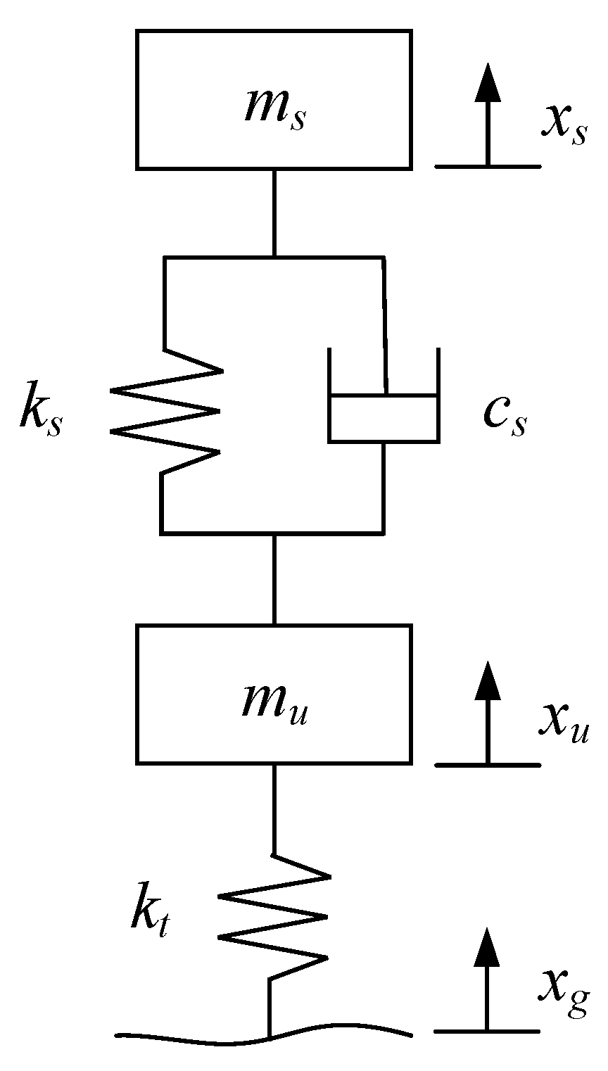
35]. In this section, the vertical vibration characteristics of each vehicle are compared. A quarter car dynamic model is built to research the vertical vibration as shown in
Figure 11. In the model, the stiffness and damping are considered as constant parameters [
36,
37]. For different vehicles, they have the same quarter car model but with different parameters.
The quarter car model is described by Equation (17):
where
is the sprung mass,
is the sprung mass displacement,
is the suspension stiffness,
is the suspension damping,
is the unsprung mass,
is the unsprung mass displacement,
is the tyre stiffness,
is the road excitation. In this model, the tyre damping is ignored due to its small effect on the vertical vibration [
38]. The parameters of each vehicle are shown in
Table 5. In IEV, two CEMs are removed so that the sprung mass is reduced compared with CEV. The IEMs increase the unsprung mass. In IHV, one CEM is removed but a CHM and two accumulators are installed on-board, so the sprung mass does not significantly change. As mentioned, the IHM has a higher power density than the IEM, so the IHM mass is much smaller than the IEM with same power, which explains why the IHV unsprung mass is smaller than the IEV.
To investigate the vehicle vertical vibration characteristics under the road excitation, the state function and output functions are built as follows:
In the equation, the sprung mass displacement, sprung mass velocity, unsprung mass displacement, and unsprung mass velocity are selected as the state vector
X. The sprung mass acceleration, unsprung mass acceleration, suspension deformation and tyre deformation are selected as the output vector
Y [
39]. The road excitation is selected as the input vector.
From Equation (17), the state function and output function are obtained as shown in Equations (20) and (21).
The frequency response analysis under road excitation with 1 m amplitude and different frequencies is conducted and the results are shown in
Figure 12. There are two natural frequencies in the quarter car system. In IEV, the natural frequencies and amplitudes are all greatly changed. In IHV, the first natural frequency is very close to the CEV but the second natural frequency is decreased.
Figure 12a shows the sprung mass acceleration frequency response to the road excitation. It is shown that the sprung mass acceleration is significantly increased in IEV with both natural frequencies, which indicates a worse driving comfort. The IHV sprung mass acceleration response is almost the same as the CEV at the first natural frequency. At the second natural frequency, the IHV sprung mass acceleration response is only slightly higher than the CEV. So from the vertical acceleration perspective, the IHV maintains the vehicle driving comfort while the IEV degrades the driving comfort.
Figure 12b shows that the unsprung mass acceleration responses of all vehicles are quite small at the first natural frequency. At the second natural frequency, the acceleration response of IEV and IHV are reduced due to larger unsprung mass.
The suspension deformation with different excitation frequencies is shown in
Figure 12c. The IEV has a reduced suspension deformation at the first natural frequency; however, it has an increased suspension deformation at the second natural frequency. The IHV suspension deformation is also larger than the CEV at the second natural frequency. It should also be noticed that although the suspension deformations of IEV and IHV are increased at the second natural frequency, they are still smaller than the CEV suspension deformation at the first natural frequency.
The tyre deformation, which represents the dynamic wheel load, is shown in
Figure 12d. It is demonstrated that at the first natural frequency, the larger unsprung mass in IEV and IHV do not remarkably increase the wheel loads. However, the wheel loads are increased a lot at the second natural frequency in IEV and IHV, which proposes higher requirements for tyre strength. The IHV dynamic wheel load is smaller than the IEV dynamic wheel load.
7. Conclusions
This paper compares the energy economy and vibration characteristics of CEV, IEV and IHV. By the energy management strategy designed with the DP algorithm, the IEV and IHV consume more energy than the CEV, which makes IEV and IHV incompetent for energy saving. In addition to the advantages of independent wheel torque control, the IEV and IHV also have the vibration problems caused by increased unsprung mass. The hydraulic motor has a higher power density than the electric motor, and so less unsprung mass is added in the IHV than the IEV. The vibration analysis results demonstrate that the vibration problems caused by increased unsprung mass could be alleviated in IHV, especially in the vehicle body acceleration, which directly affects driving comfort. Besides, the heat dissipation and IEM high voltage safety challenges are cancelled in IHV. Based on the above analysis, the IHV is more suitable for off-road vehicles which work in harsh conditions such as mining, forestry and agriculture vehicles. For these vehicles, the in-wheel drive improves the vehicle handling performance and agility by independent wheel torque control. Hydraulic motors also have a better reliability under bad working conditions such as muddy ground.
In the future, the following researches could be conducted. Firstly, this paper researches the optimal energy consumption of each vehicle by DP. It is a global optimization method, which helps to find the least energy consumption over a known driving condition. In real driving, it is hard to get prior driving condition information and so rule-based or real-time optimization energy management strategies should be designed. Secondly, the longitudinal vibration also deserves research. Comparisons could be made on how the IHM and IEM torque affect the vehicle longitudinal vibration. Besides, the lateral dynamics are also changed by different unsprung mass, which affects the steering control and the torque vector control.
Author Contributions
Conceptualization, S.Z. and Y.T.; Formal analysis, S.Z.; Investigation, S.Z.; Methodology, Y.T. and C.T.N.; Supervision, P.W. and N.Z.; Writing—original draft, S.Z.; Writing—review and editing, P.W. All authors have read and agreed to the published version of the manuscript.
Funding
This research was funded by China Scholarship Council grant number 201706130135 and Australian Research Council grant number DE0170100134.
Institutional Review Board Statement
Not applicable.
Informed Consent Statement
Not applicable.
Data Availability Statement
The data presented in this study are available on request from the corresponding author. The data are not publicly available due to confidentiality.
Conflicts of Interest
The authors declare no conflict of interest.
References
- De Pinto, S.; Camocardi, P.; Chatzikomis, C.; Sorniotti, A.; Bottiglione, F.; Mantriota, G.; Perlo, P. On the Comparison of 2- and 4-Wheel-Drive Electric Vehicle Layouts with Central Motors and Single- and 2-Speed Transmission Systems. Energies 2020, 13, 3328. [Google Scholar] [CrossRef]
- Zeng, M.; Tan, B.; Ding, F.; Zhang, B.; Zhou, H.; Chen, Y. An experimental investigation of resonance sources and vibration transmission for a pure electric bus. Proc. Inst. Mech. Eng. Part D J. Automob. Eng. 2020, 234, 950–962. [Google Scholar] [CrossRef]
- Shao, L.; Karci, A.E.H.; Tavernini, D.; Sorniotti, A.; Cheng, M. Design Approaches and Control Strategies for Energy-Efficient Electric Machines for Electric Vehicles—A Review. IEEE Access 2020, 8, 116900–116913. [Google Scholar] [CrossRef]
- Hu, J.; Ran, H.; Pang, T.; Zhang, Y. Parameter design and performance analysis of shift actuator for a two-speed automatic mechanical transmission for pure electric vehicles. Adv. Mech. Eng. 2016, 8, 168781401666425. [Google Scholar] [CrossRef] [Green Version]
- Guo, L.; Gao, B.; Chen, H. Online Shift Schedule Optimization of 2-Speed Electric Vehicle Using Moving Horizon Strategy. IEEE/ASME Trans. Mechatron. 2016, 21, 2858–2869. [Google Scholar] [CrossRef]
- Liang, J.; Walker, P.D.; Ruan, J.; Yang, H.; Wu, J.; Zhang, N. Gearshift and brake distribution control for regenerative braking in electric vehicles with dual clutch transmission. Mech. Mach. Theory 2019, 133, 1–22. [Google Scholar] [CrossRef]
- Tian, Y.; Yang, H.; Mo, W.; Zhou, S.; Zhang, N.; Walker, P.D. Optimal coordinating gearshift control of a two-speed transmission for battery electric vehicles. Mech. Syst. Signal Process. 2020, 136, 106521. [Google Scholar] [CrossRef]
- Wang, W.; Li, J.; Sun, F. Pseudo-spectral optimisation of smooth shift control strategy for a two-speed transmission for electric vehicles. Veh. Syst. Dyn. 2019, 604–629. [Google Scholar] [CrossRef]
- Ruan, J.; Walker, P.; Zhang, N. A comparative study energy consumption and costs of battery electric vehicle transmissions. Appl. Energy 2016, 165, 119–134. [Google Scholar] [CrossRef] [Green Version]
- Bottiglione, F.; De Pinto, S.; Mantriota, G.; Sorniotti, A. Energy Consumption of a Battery Electric Vehicle with Infinitely Variable Transmission. Energies 2014, 7, 8317–8337. [Google Scholar] [CrossRef] [Green Version]
- Murata, S. Innovation by in-wheel-motor drive unit. Veh. Syst. Dyn. 2012, 50, 807–830. [Google Scholar] [CrossRef]
- De Novellis, L.; Sorniotti, A.; Gruber, P.; Pennycott, A. Comparison of Feedback Control Techniques for Torque-Vectoring Control of Fully Electric Vehicles. IEEE Trans. Veh. Technol. 2014, 63, 3612–3623. [Google Scholar] [CrossRef] [Green Version]
- Shuai, Z.; Zhang, H.; Wang, J.; Li, J.; Ouyang, M. Combined AFS and DYC Control of Four-Wheel-Independent-Drive Electric Vehicles over CAN Network with Time-Varying Delays. IEEE Trans. Veh. Technol. 2014, 63, 591–602. [Google Scholar] [CrossRef]
- Lim, D.; Lee, M.Y.; Lee, H.S.; Kim, S. Performance Evaluation of an In-Wheel Motor Cooling System in an Electric Vehicle/Hybrid Electric Vehicle. Energies 2014, 7, 961–971. [Google Scholar] [CrossRef] [Green Version]
- Tan, D.; Lu, C. The Influence of the Magnetic Force Generated by the In-Wheel Motor on the Vertical and Lateral Coupling Dynamics of Electric Vehicles. IEEE Trans. Veh. Technol. 2016, 65, 4655–4668. [Google Scholar] [CrossRef]
- Zhou, H.; Xu, Z.; Liu, L.; Liu, D.; Zhang, L. A Rule-Based Energy Management Strategy Based on Dynamic Programming for Hydraulic Hybrid Vehicles. Math. Probl. Eng. 2018, 2018, 1–10. [Google Scholar] [CrossRef] [Green Version]
- Zhou, S.; Walker, P.; Zhang, N. Parametric design and regenerative braking control of a parallel hydraulic hybrid vehicle. Mech. Mach. Theory 2020, 146, 103714. [Google Scholar] [CrossRef]
- Wang, L.; Liu, X.; Wang, X.; Fu, B.; Xu, R. Research on differential performance of four-wheel independent steering of a hydraulic wheel-driving off-road vehicle. J. Eng. 2019, 2019, 68–73. [Google Scholar] [CrossRef]
- Niu, G.; Shang, F.; Krishnamurthy, M.; Garcia, J.M. Design and Analysis of an Electric Hydraulic Hybrid Powertrain in Electric Vehicles. IEEE Trans. Transp. Electrif. 2017, 3, 48–57. [Google Scholar] [CrossRef]
- Honey, E.; Suh, I.-S. A feasibility study of an electric–hydraulic hybrid powertrain for passenger vehicles. Proc. Inst. Mech. Eng. Part D J. Automob. Eng. 2015, 229, 1894–1906. [Google Scholar] [CrossRef]
- Hui, S.; Lifu, Y.; Junqing, J. Hydraulic/electric synergy system (HESS) design for heavy hybrid vehicles. Energy 2010, 35, 5328–5335. [Google Scholar] [CrossRef]
- Leon, J.; Garcia, J.M.; Acero, M.J.; Gonzalez, A.; Niu, G.; Krishnamurthy, M. Case Study of an Electric-Hydraulic Hybrid Propulsion System for a Heavy Duty Electric Vehicle; SAE: Indiana, IL, USA, 2016. [Google Scholar]
- Yang, Z.; Shang, F.; Brown, I.P.; Krishnamurthy, M. Comparative Study of Interior Permanent Magnet, Induction, and Switched Reluctance Motor Drives for EV and HEV Applications. IEEE Trans. Transp. Electrif. 2015, 1, 245–254. [Google Scholar] [CrossRef]
- Chen, Z.; Vahidi, A. Route Preview in Energy Management of Plug-in Hybrid Vehicles. IEEE Trans. Control Syst. Technol 2012, 20, 546–553. [Google Scholar] [CrossRef]
- Liu, T.; Tang, X.; Wang, H.; Yu, H.; Hu, X. Adaptive Hierarchical Energy Management Design for a Plug-In Hybrid Electric Vehicle. IEEE Trans. Veh. Technol. 2019, 68, 11513–11522. [Google Scholar] [CrossRef]
- Wei, J.; Guo, K.; Fang, J.; Tian, Q. Nonlinear supply pressure control for a variable displacement axial piston pump. Proc. Inst. Mech. Eng. Part I J. Automob. Eng. 2015, 229, 614–624. [Google Scholar] [CrossRef]
- Kemmetmüller, W.; Fuchshumer, F.; Kugi, A. Nonlinear pressure control of self-supplied variable displacement axial piston pumps. Control Eng. Pract. 2010, 18, 84–93. [Google Scholar] [CrossRef]
- Ning, X.; Shangguan, J.; Xiao, Y.; Fu, Z.; Xu, G.; He, A.; Li, B. Optimization of Energy Recovery Efficiency for Parallel Hydraulic Hybrid Power Systems Based on Dynamic Programming. Math. Probl. Eng. 2019, 2019, 1–11. [Google Scholar] [CrossRef]
- Pfeffer, A.; Glück, T.; Kemmetmüller, W.; Kugi, A. Mathematical modelling of a hydraulic accumulator for hydraulic hybrid drives. Math. Comput. Model. Dyn. Syst. 2016, 22, 397–411. [Google Scholar] [CrossRef]
- Peng, J.; He, H.; Xiong, R. Rule based energy management strategy for a series–parallel plug-in hybrid electric bus optimized by dynamic programming. Appl. Energy 2017, 185, 1633–1643. [Google Scholar] [CrossRef]
- Park, S.; Ahn, C. Power Management Controller for a Hybrid Electric Vehicle With Predicted Future Acceleration. IEEE Trans. Veh. Technol. 2019, 68, 10477–10488. [Google Scholar] [CrossRef]
- Lin, C.; Zhao, M.; Pan, H.; Yi, J. Blending gear shift strategy design and comparison study for a battery electric city bus with AMT. Energy 2019, 185, 1–14. [Google Scholar] [CrossRef]
- Zhang, X.; Gohlich, D.; Li, J. Energy-Efficient Toque Allocation Design of Traction and Regenerative Braking for Distributed Drive Electric Vehicles. IEEE Trans. Veh. Technol. 2018, 67, 285–295. [Google Scholar] [CrossRef]
- Song, Z.; Hofmann, H.; Jianqiu, L.; Wang, Y.; Lu, D.; Ouyang, M.; Du, J. Torque Distribution Strategy for Multi-PMSM Applications and Optimal Acceleration Control for Four-Wheel-Drive Electric Vehicles. J. Dyn. Syst. Meas. Control 2020, 142. [Google Scholar] [CrossRef]
- Van Schalkwyk, D.; Kamper, M. Effect of hub motor mass on stability and comfort of electric vehicles. In Proceedings of the 2006 IEEE Vehicle Power and Propulsion Conference, Windsor, UK, 6–8 September 2006; IEEE: Piscataway, NJ, USA, 2006; pp. 1–6. [Google Scholar]
- Qi, H.; Chen, Y.; Zhang, N.; Zhang, B.; Wang, D.; Tan, B. Improvement of both handling stability and ride comfort of a vehicle via coupled hydraulically interconnected suspension and electronic controlled air spring. Proc. Inst. Mech. Eng. Part D J. Automob. Eng. 2019, 234, 552–571. [Google Scholar] [CrossRef]
- Liu, M.; Zhang, Y.; Huang, J.; Zhang, C. Optimization control for dynamic vibration absorbers and active suspensions of in-wheel-motor-driven electric vehicles. Proc. Inst. Mech. Eng. Part D J. Automob. Eng. 2020, 234, 2377–2392. [Google Scholar] [CrossRef]
- Zhao, L.; Zhou, C.; Yu, Y.; Yang, F. An analytical formula of driver RMS acceleration response for quarter-car considering cushion effects. Veh. Syst. Dyn. 2017, 55, 1283–1296. [Google Scholar] [CrossRef]
- Ślaski, G.; Gudra, A.; Borowicz, A. Analysis of the influence of additional unsprung mass of in-wheel motors on the comfort and safety of a passenger car. Arch. Motoryz. 2014, 65, 51–64. [Google Scholar]
| Publisher’s Note: MDPI stays neutral with regard to jurisdictional claims in published maps and institutional affiliations. |
© 2021 by the authors. Licensee MDPI, Basel, Switzerland. This article is an open access article distributed under the terms and conditions of the Creative Commons Attribution (CC BY) license (https://creativecommons.org/licenses/by/4.0/).


