1. Introduction
Modular multilevel converters (MMCs) were first used in high voltage applications, then in medium voltage, and lately in low voltage. In high voltage applications, they are used in high voltage direct current (HVDC) transmission [
1,
2,
3], including the connection of offshore wind farms to the onshore grid. In medium voltage applications, they have been used in static synchronous compensator (STATCOM) [
4,
5] and motor/generator drivers [
6].
Small- to medium-sized wind generators are connected to the grid via two-level three-phase back-to-back converters [
7]. The generator-side inverter is responsible for tracking the maximum power point (MPPT) [
8,
9], while the second converter is connected to the grid through a filter to reduce harmonics due to pulse width modulation (PWM). When the number of wind turbines is high, they are connected in parallel after the filter and before the low or medium voltage grid connection transformer.
The system proposed in this paper places each wind generator inside a switching module (SM) of the MMC. As in any MMC, if the number of SMs per arm is small, the output voltage is obtained by multilevel PWM [
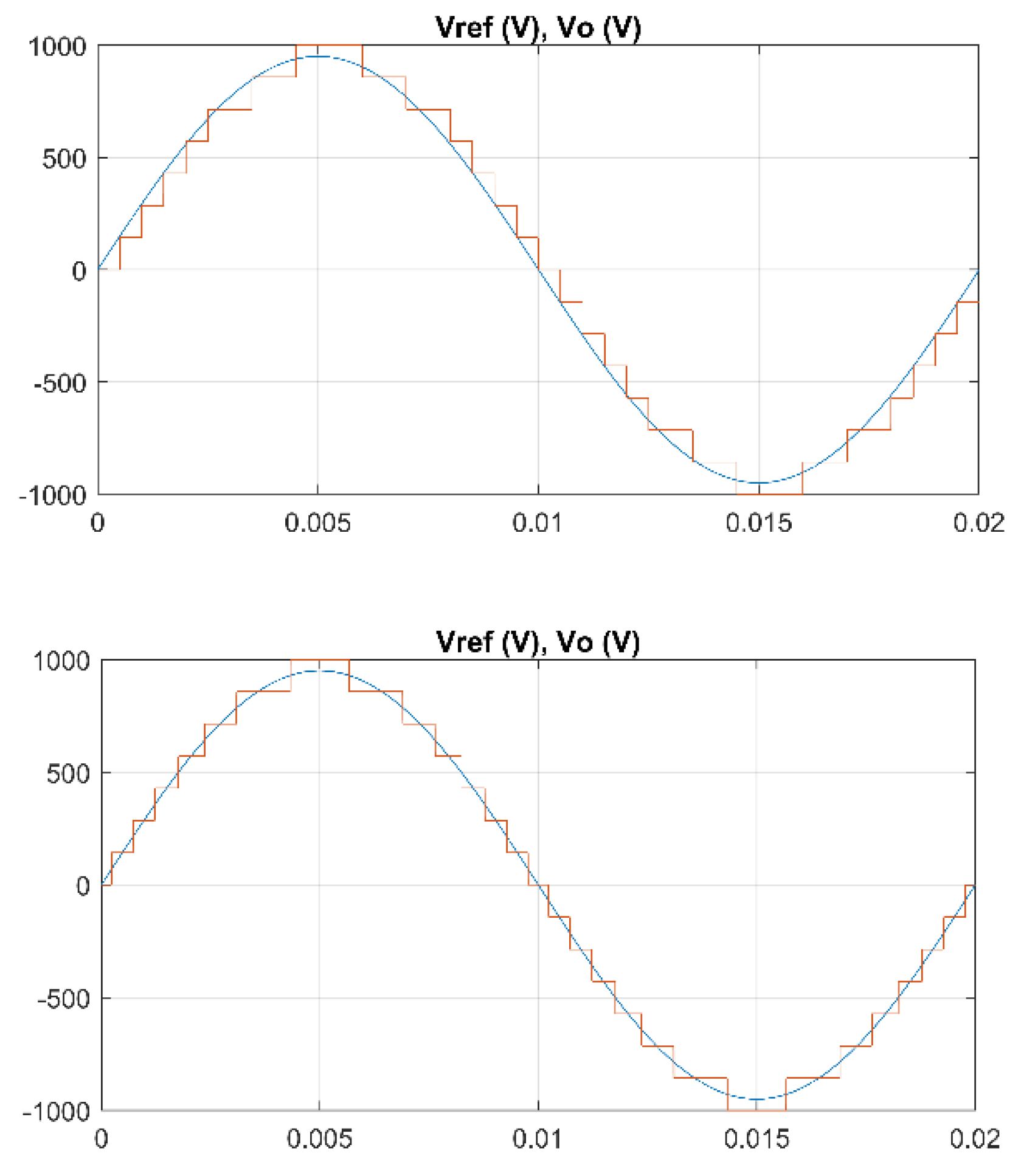
10] because the number of output voltage levels is low. However, if the number of generators is high (larger number of voltage levels) it is better to use near level control (NLC) [
11], because its switching losses are much lower. Therefore, when the number of generators is small (e.g., 30) it is more appropriate to use PWM, while if the number of generators is high (e.g., 60) it is better to use NLC. The second case is the one analyzed in this article.
Some authors have presented the integration of battery energy storage (BES) in the SMs of an MMC [
12,
13,
14], mainly for medium voltage applications. These works are intended to solve the problems of having a very large number of battery elements in series when two- or three-level converters are used. The mentioned problems are mainly imbalances between battery modules and reduced reliability because the failure of one battery module can render the entire battery unusable. The integration of batteries into MMC SMs can solve both problems. The use of control systems makes it possible to eliminate imbalances that may appear between phases and arms, and to operate when the grid is unbalanced [
13]. The work presented in [
12] studies the case where some SMs include batteries and others do not. A slightly different application is the integration of the storage batteries of a group of electric vehicles in an MMC; a control that takes into account the different charging situations of the vehicles has been proposed in [
15].
Integration of solar panels into the MMC structure, by including a panel or a group of panels in each SM, can be found in the literature. In [
16], DC/DC converters have been used to connect the solar panel to the SM, which carries out the MPPT and makes it possible to eliminate the grid-connection transformer. In [
17], the application to a multi-megawatt photovoltaic plant, using SMs with full-bridge topology, is studied, and MPPT is performed. In [
18], a solar panel is included in each SM, and a control system is developed to perform the MPPT without the need to use a DC/DC converter in each SM; also, a redundant module is added in each arm to balance the voltages of each phase.
MMCs that include solar panels in some SMs and batteries in other SMs have been proposed to reduce the variations of the generated power due to solar radiation variations. In [
19], both solar panels and batteries are connected to the SM by isolated DC/DC converters.
The integration of decentralized energy resources (DER) in an MMC is analyzed in [
20]. The authors noted the need to transfer power between phases and arms as a result of generation differences and proposed using regulators to balance power generation.
As stated above, it is possible to find works in the technical literature in which batteries, solar panels, or both have been included within the MMC topology. Some of them analyze how to handle the power imbalances between phases and between arms by using regulators responsible for delivering the same power through each of the phases even though the generation is unbalanced. These regulators are difficult to apply to this case since they have been developed for PWM, not for NLC; they are based on generating a voltage difference between the upper and lower arms, and, in the case of NLC, that causes large ripples of circulating current due to the low switching frequency.
This paper proposes a topology that integrates wind generators in an MMC with NLC, which is especially suitable for wind farms with a high number of generators. The paper includes a theoretical analysis of the power transfer between phases and arms. Using simulation, it is shown that it is possible to find parameter values that allow a correct operation without the need for regulators to transfer power between phases and arms and without a large increase in the arm currents.
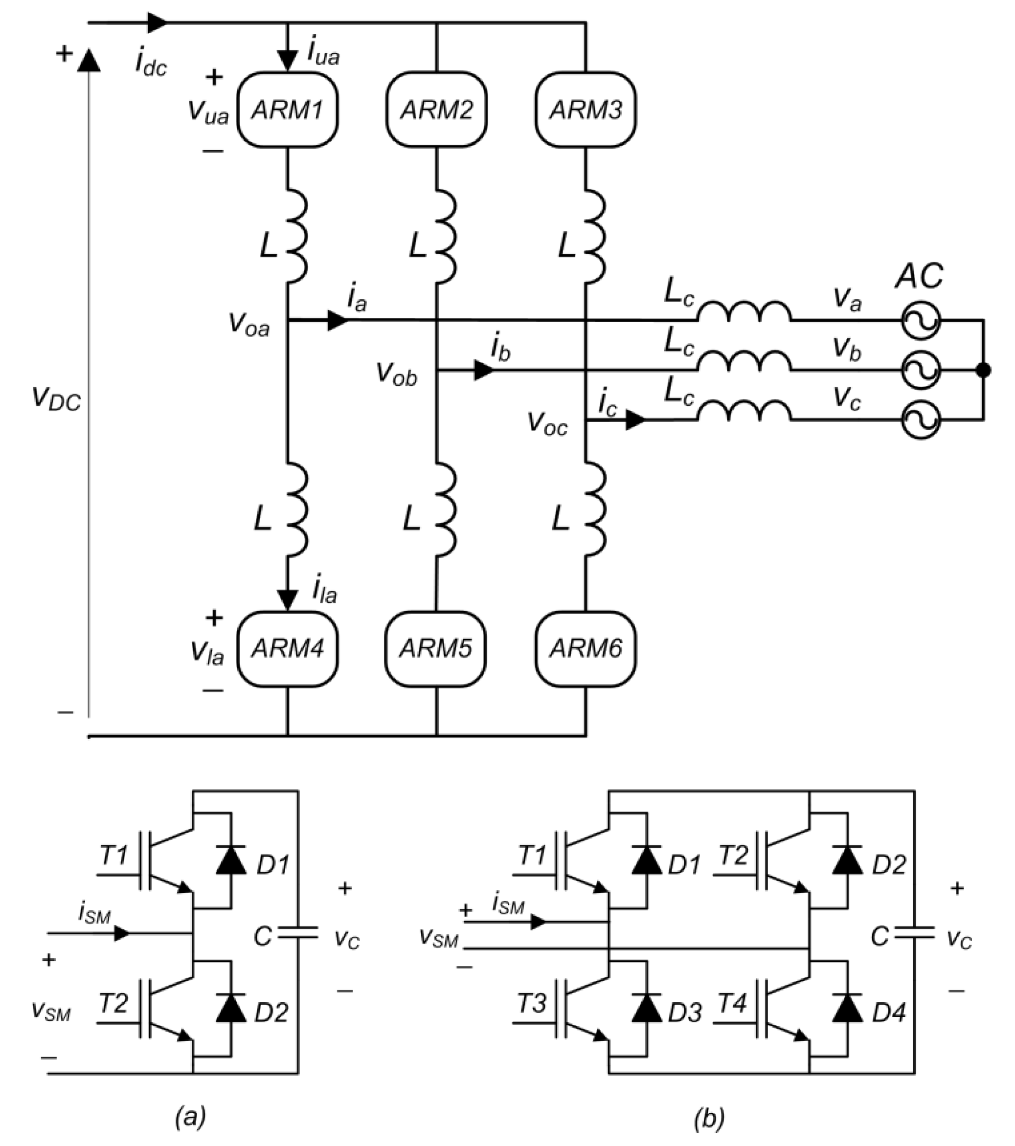
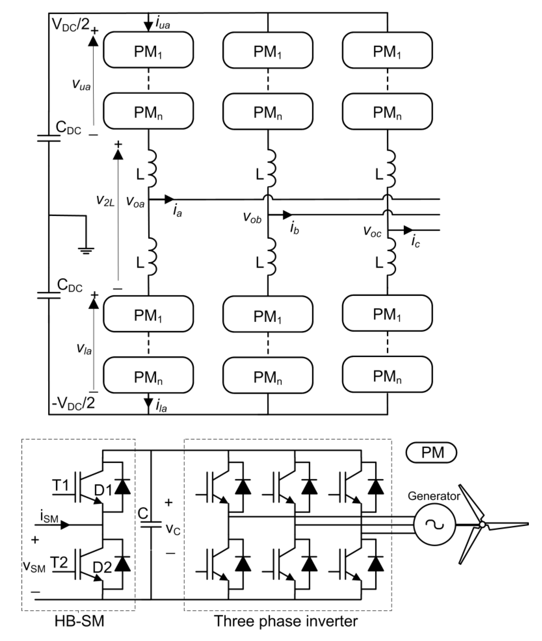
The proposed topology has advantages, such as the use of fewer semiconductors, lower switching losses, and reduced filtering requirements. The number of semiconductors per wind generator is reduced from 12 to 8 IGBTs by replacing the grid-side converter with the half-bridge (HB) of the SM. The use of NLC instead of PWM reduces the switching frequency of the semiconductors and their power losses. In the classical wind farm configuration, the converter of each generator is connected to the grid through a filter (L or LCL), so the same number of filters is needed as the number of generators; however, in the developed topology, a single small filter is needed, due to the multilevel voltage, which can even be eliminated in many cases.
Compared to the previously cited articles, this paper mainly presents two novel aspects. The first one is the inclusion of wind turbines within the modules of an MMC, whereas existing references have only studied the inclusion of solar panels and/or batteries. The second is the analysis of the power generation balancing between phases and arms; the literature had proposed regulators to perform such balancing, but this paper studies a case in which the system can be balanced automatically without the need to use regulators.
The article is structured as follows.
Section 2 includes a short introduction to MMC and NLC.
Section 3 explains the new topology and the control used.
Section 4 provides a theoretical study of the variables involved in the power transfer between phases and between arms, which is necessary when the generation is unbalanced.
Section 5 studies the case chosen to demonstrate that this configuration can work correctly even when there are large imbalances in the power generation. Finally,
Section 6 presents the conclusions of the work.
4. Power Transfer between Phases and between Arms
This section addresses the situation that takes place when there are generation imbalances between phases and between arms. It must be taken into account that the vector control system proposed in
Figure 4 delivers the same power to the grid through each of the three phases. Therefore, if each phase generates a different power, there must be a mechanism that allows power transfer between the phases. Regarding the arms, the converter tends to deliver half of the phase power from each of the arms, because half of the current of each phase flows through each of the arms that are connected to it. Therefore, there must be a mechanism to transfer power between the two arms of a phase, or, in other words, to send different powers from each of the two arms.
Generation imbalances within the PMs of the same arm do not cause any problem, since they are balanced by the PM capacitor voltage ordering algorithm.
The best situation is when there is balance in the generation of all wind generators, but there will be cases where the generation is unbalanced. Therefore, the four possible cases are listed in
Table 3.
The vector control ensures that each phase delivers the same AC power so that the system is balanced. If the power generated in each phase and/or in each arm is different, there must be internal power balancing mechanisms, otherwise, the system would be unbalanced. This analysis is made in detail below.
4.1. Balanced Generation
In this case, all wind turbines generate the same power, so the power generated in the arms and the phases is balanced. No power has to be transferred between phases or arms so that the AC power delivered through each phase is the same.
4.2. Imbalance between Phases
In this case, it will be considered that the power generated by the wind turbines of each phase is the same, but that the power generated by each turbine of one phase is different from the power generated by the turbine of another phase. Since the AC power to be delivered in each phase must be the same, there must be power transfer from the phases that generate more power to the phases that generate less power.
The continuous component of the circulating current of phase
,
, is responsible for sending/receiving power on phase
i to/from other phases. The circulating current of phase
,
, consists of a continuous component
, the first harmonic of the alternating component (50 Hz)
and the second harmonic of the alternating component (100 Hz)
,
The product of the DC component of the circulating current
by the DC voltage
is the power absorbed by that phase, and which has been sent from the other phases. By reversing the sign of this power, the power delivered by phase
,
, to the other two phases is obtained.
Since the sum of the circulating currents of the three phases is zero, the sum of the continuous components of the three circulating currents and the sum of the powers transferred between the three phases will also be zero.
In the analysis of the sub-cases of
Section 5.2.1 and
Section 5.2.2, it will be seen that this power transfer occurs naturally without the use of any type of regulator.
4.3. Imbalance between Arms
In this case, it is going to be considered that the power generated by the three upper arms of the three phases is equal (), that the power generated by the three lower arms of the three phases is equal (), but that the power generated by the upper and lower arms is different,. In this situation, the power generated by each phase is the same and it is the sum of the powers of the upper and lower arms, . Therefore, there is no need to transfer power between the phases.
In the absence of a 50 Hz circulating current, the power supplied by the upper and lower arms is the same, because the current of each phase of the converter is divided by 50% between the two arms, upper and lower. Since the AC voltage of the upper and lower arms is equal, and the arm power is the product of the 50 Hz voltage and the 50 Hz current, then the powers of the upper and lower arms would be equal. For the upper and lower arms to be able to deliver an AC power equal to the power they generate (different from each other), there must be a 50 Hz circulating current that, according to Equation (4) and considering that = 0, allows it. In the following, all this will be analyzed in detail and the equations that describe it will be obtained.
From Equation (4), and taking into account that
= 0, the current of the upper (lower) arm is:
The power delivered by the upper (lower) arm of phase
in 50 Hz AC is:
where the subscript “1” means the first harmonic (50 Hz). The 50 Hz voltage of the upper (lower) arm
has a value approximately equal to the converter output voltage
, assuming that the voltage on the arm inductance is very small,
The 50 Hz circulating current
is the quotient of the voltage of the two arm inductances
and the impedances of the two arm inductances
,
where the voltage of the two inductances
is obtained as
From Equations (11)–(13), the expression of the power generated in the upper (lower) arm is obtained,
Given Equation (16), it is observed that the circulating current allows that the power delivered by the upper and lower arms can be different, which is what is desired when the generation is different. This circulating current is generated due to the difference between the voltages of the two arms, and , which occurs due to the voltage differences of the upper and lower arm capacitors.
The voltage of the first AC harmonic of the upper
and lower
arms is generated by NLC modulation, the levels of which are formed by the voltage of the capacitors of the SMs. If the voltage of these capacitors increases or decreases a little, the peak value of the voltages
and
also increases or decreases a little. This is what happens when there is an imbalance in the generation between the upper and lower arms. If, for example, the generation of the upper arm is lower than that of the lower arm, the voltage of the capacitors of the upper and lower arms is reduced and increased a little, respectively, until a circulating current is generated, according to Equation (14), which allows the power of the wind generators of the arm to be equal to the power delivered by that arm to the output of the converter. All this can be seen by the examples in
Section 5.3.1 and
Section 5.3.2 and is explained graphically below in
Figure 5. In that, the arm voltage vectors
have been placed (for simplicity the subscripts
are replaced by
), from which the value of
, called in a simplified form
, is obtained by Equation (15). By means of Equation (14),
, called
, is obtained; and by means of Equation (11), the currents of the arms,
, are obtained. The active power delivered by each arm is calculated by means of the rms values of the voltages and currents:
As can be seen in
Figure 5, the presence of the circulating current allows the currents
to have different values and therefore the powers
to have different values in turn.
4.4. Imbalance between Phases and Arms
This case is not analyzed because it is a combination of the cases of
Section 4.2 and
Section 4.3, already analyzed.
5. Analysis of a Case for Different Generation Scenarios
In this section, a case (a topology and control) to integrate a large number of wind generators into the structure of an MMC has been proposed. Specific parameters of capacitors and inductances have been selected, together with the parameters of the PI regulators, by trial and error to obtain a good performance for very wide operating ranges. The following sub-cases have been tested: balanced generation of all generators for high and medium powers, unbalanced generation between phases when these imbalances are medium and when they are large, and unbalanced generation between arms for medium and large imbalances. The analysis has been carried out by simulation with Matlab/Simulink, using the parameters shown in
Table 4. These parameters have been chosen by trial and error to obtain a balance between several parameters: 100 Hz circulating current amplitude, capacitor voltage ripple, DC voltage ripple, and dynamic response. A model replaces the wind generator with a current source of a value equal to the quotient of the wind generator power
and the PM capacitor voltage
(
Figure 6). The study method presented in this paper, as indicated above, is based on the interpretation of the data obtained by means of the simulation in Matlab/Simulink of the models shown in
Figure 3 and
Figure 4. In order to find an optimal relationship between the simulation time and the reduction of errors in the data obtained in the simulation, it was chosen:
Three cases have been chosen: balanced generation, phase imbalance, and arm imbalance. Only the case of simultaneous phase and arm unbalance is missing, but it is a combination of the last two cases. Balanced generation cases correspond to actual cases where all generators are running and wind speeds are average or high. Phase or arm differences correspond to actual cases where generation is different or even zero for some generators. Generation differences may be transient due to gusty winds or permanent due to the location of the turbines. Null generation is due to broken generators or generators under maintenance.
The events that one or more turbines may suffer are, mainly, the reduction of power caused by the decrease in wind speed, and the non-generation of power when the turbine is out of service or undergoing maintenance. Both cases are included within the cases studied, because in both the power generated by the arm and/or the phase is reduced.
The imbalances to be analyzed are very large, so much so that they will probably not occur in actual applications, but this will ensure the correct operation of the system. In addition, when inter-arm imbalances occur, the case where several generators stop working will be simulated, which is a tougher case than if the output of all generators is reduced by the same amount.
5.1. Balanced Generation
5.1.1. Balanced Generation and Medium Power
In this subsection and the following one, two situations are studied in which all the PMs generate the same power; in this subsection, they generate half the rated power, 750 W, and in the following subsection, they generate the rated power, 1500 W.
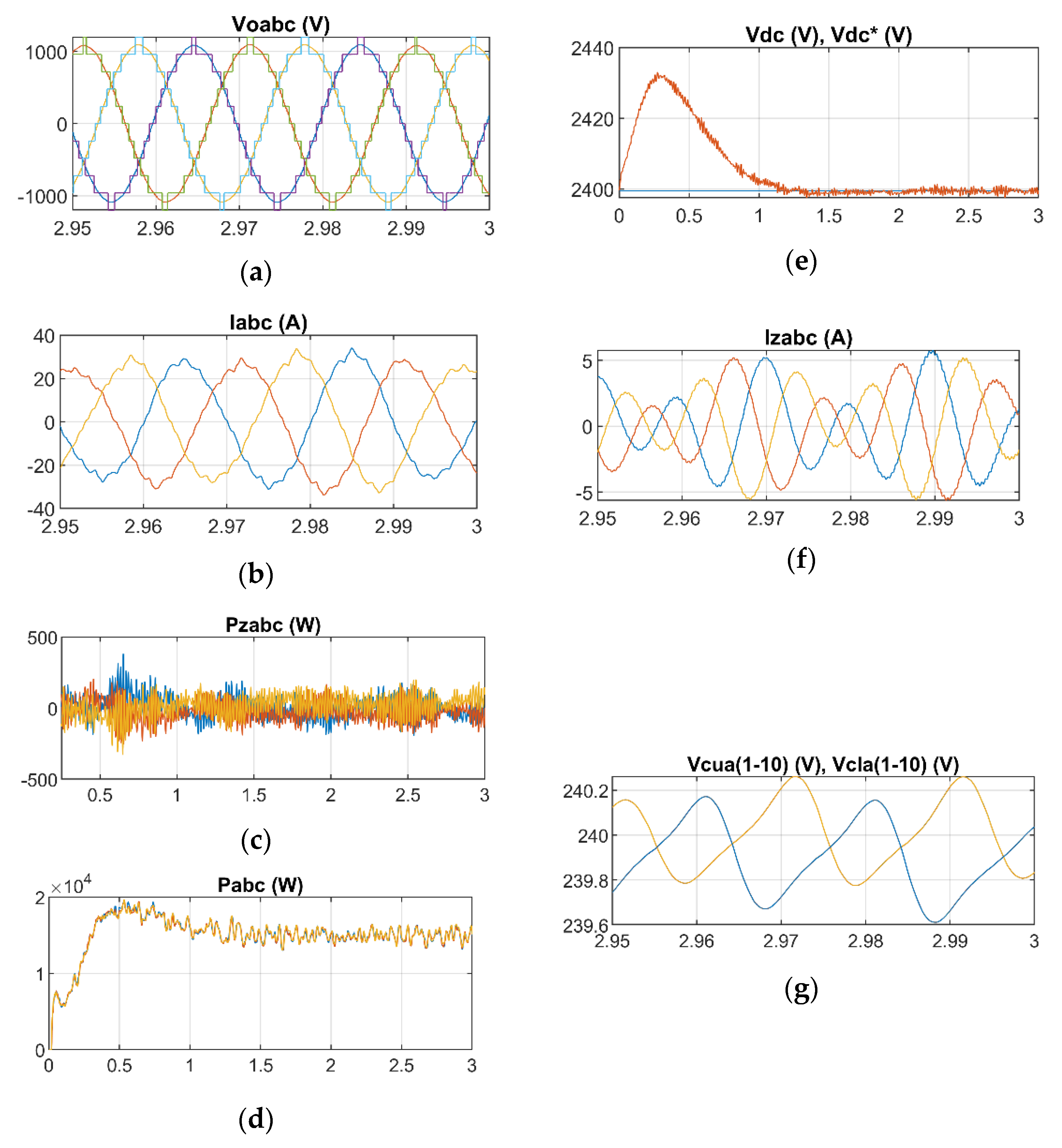
Since all generators deliver the same power of 750 W, each phase delivers a power
. The simulation results are presented in
Figure 7. It is observed that the output voltage of the MMC
(
Figure 7a) has 11 levels, as corresponds to 10 SM per arm and submits a correct waveform; the output currents of the MMC
(
Figure 7b) also have a correct waveform. The output voltage
waveform (
Figure 7a) is the same in all cases, so it will not be repeated in each case. The power transferred between phases
(
Figure 7c) is zero (only a high frequency ripple) because there is no imbalance between the phases. The power delivered by each phase
(
Figure 7d) is equal to 15 kW in each of the three phases, the same as the power generated by each phase. The voltage on the DC link
(
Figure 7e) has a small peak during start-up and then remains constant with a very small ripple. The circulating currents
(
Figure 7f) have a moderate value (
Table 5) of 3.64 A for the 100 Hz harmonic and 2.08 A for the 50 Hz harmonic. The last two plots (
Figure 7g) show the values of the capacitor voltages of the upper
and lower
arm modules, which are overlapped. A small ripple of about 0.5 V and average voltages of about 240 V are observed, both in the capacitors of the upper and lower arms.
5.1.2. Balanced Generation and Full Power
In this case, all generators deliver the same power of 1.5 kW, which is their maximum or rated power, and therefore each phase delivers
. As can be seen in
Figure 8a, the MMC output currents
are correct. The DC power transmitted between phases
(
Figure 8b) is zero, except for a small ripple, because all phases produce the same power. The power sent to the grid
(
Figure 8c) is equal in all three phases and equal to the power generated in each phase, 30 kW. The voltage on the DC link
(
Figure 8d) peaks at 60 V during start-up and then remains constant. The circulating current
has admissible values, 7.11 A (100 Hz) and 0.64 A (50 Hz) (
Table 5). The capacitor voltages of the upper
and lower
modules (
Figure 8e) have a ripple of about 1 V and an average value of about 240 V, which are appropriate values.
5.2. Imbalance between Phases
5.2.1. Medium Imbalance between Phases
In this sub-section and the following one, the situation of generation imbalance between phases is addressed. In this sub-section, a medium imbalance is simulated and in the next one, a large imbalance is simulated.
Each of the 20 generators in arms a, b, and c supply 500 W, 750 W, and 1000 W each, respectively. The total power generated by each phase is:
,
,
. Therefore, there is a transfer of 5 kW of power from the third phase (
) to the first phase (
), as can be seen in
Figure 9b. Once this transfer of power between phases is carried out, the power delivered by each phase in AC
is equal in the three phases, and having a value equal to the average power, 15 kW (
Figure 9c). It is observed in
Figure 9a that the MMC currents
are correct. The DC link voltage
has a small peak of 30 V during start-up and then remains constant (
Figure 9d). The circulating currents of the first
and third
phases have a DC value due to the power transfer between these phases; in addition, they have small AC values (
Table 5), 3.16 A (100 Hz) and 1.94 A (50 Hz). The voltage ripple of the module capacitors is small (
Figure 9e), about 0.5 V, and their average value is 240 V, both for those of the upper arms
and those of the lower ones
.
As indicated in
Section 4.2, the generation differences between phases are balanced naturally, without the need for a regulator, by the continuous component of the circulating currents. The power received by phase a from the other phases is the product of the DC voltage (2400 V) by the average value of the circulating current of phase a (1.96 A), whose product is 4584 W. The power delivered by phase c to the other phases is the product of the DC voltage (2400 V) by the average value of the circulating current of phase c (1.91 A), whose product is 4992 W. These values match the powers generated in each of the phases (
,
,
) so that the power delivered to the grid is balanced.
5.2.2. Large Imbalance between Phases
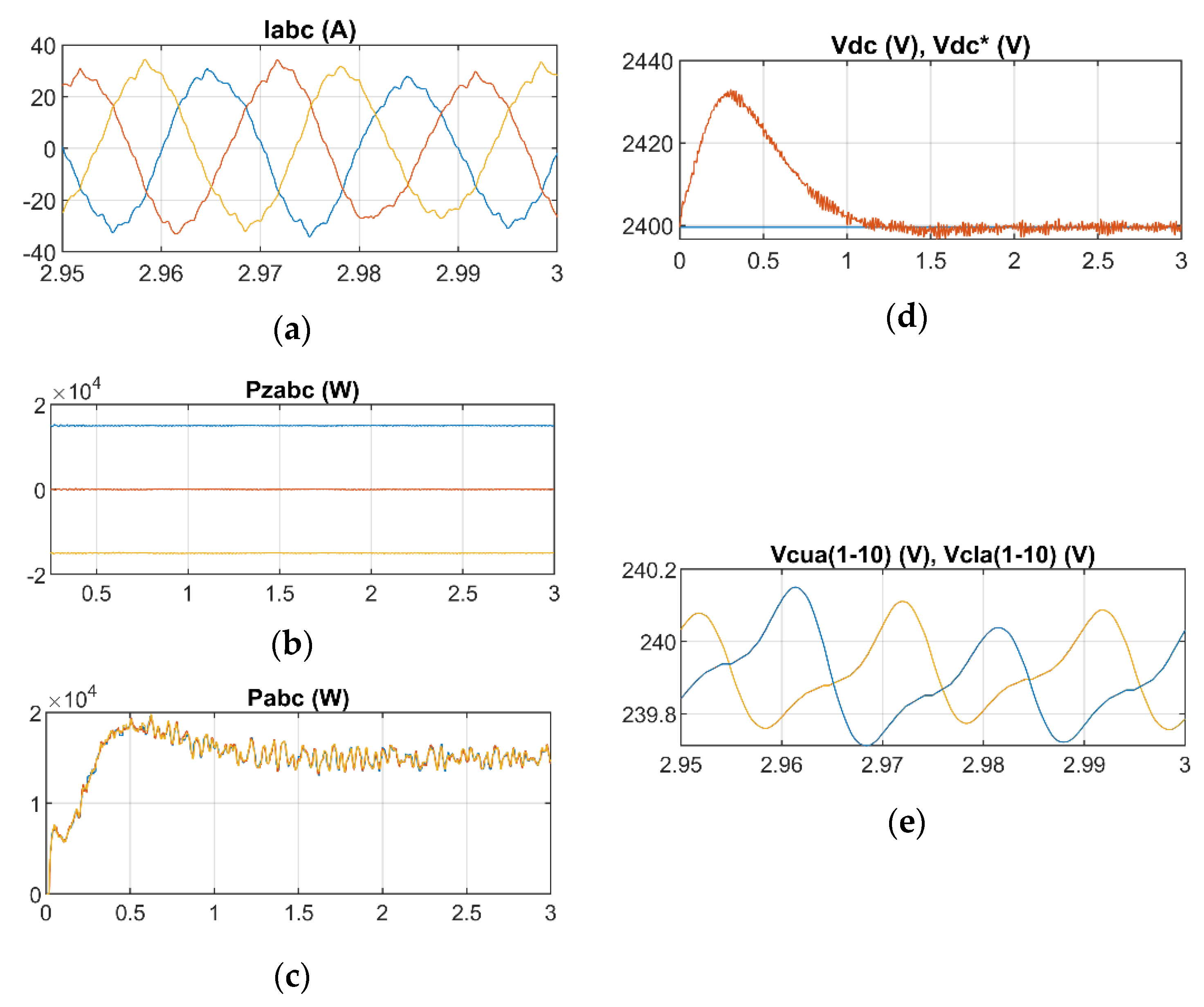
In this case, there is a large imbalance between the generation of the different phases; the generators of arms a, b, and c supply 0, 750 W, and 1500 W each, respectively. The total power supplied by each phase is:
,
,
.
Figure 10 shows that all variables are correct. The currents
of the MMC (
Figure 10a) have appropriate values. The values of the transferred powers between phases
(
Figure 10b) indicate that phase c transfers a power of 15 kW towards phase a. Thus, each of the three phases transfers the same AC power to the grid,
(
Figure 10c). The DC voltage
(
Figure 10d) is constant after a small start-up peak. The circulating currents
and
have DC values because they transfer power between phases a and c; the AC components have moderate values (
Table 5), 3.13 A (100 Hz) and 1.45 A (50 Hz). The capacitors of the modules have a ripple of 0.4 V and an average value of 240 V (
Figure 10e), with no difference between the capacitors of the upper and lower arms.
As in
Section 5.2.1, and as indicated theoretically in
Section 4.2, the generation differences between the phases are balanced naturally, without the need for a regulator, by the DC component of the circulating currents. The power received by phase a from the other phases is the product of the DC voltage (2400 V) by the average value of the circulating current of phase a (6.12 A), 14,688 W. The power delivered by phase c to the other phases is the product of the DC voltage (2400 V) by the average value of the circulating current of phase c (6.21 A), 14,904 W.
5.3. Imbalance between Arms
5.3.1. Medium Imbalance between Arms
In this sub-section and the following one, the three phases generate the same power but there is an imbalance between the upper and lower arms. This sub-section analyzes a medium imbalance situation and the following one a very high imbalance situation.
The power generated by each phase is the same,
, but the power generated in the upper and lower arms of each phase has a medium imbalance,
and
. For this, all generators supply 1500 W except 4 generators in each upper arm which generate zero power. As can be seen in the graph of the powers of the upper arm
and lower arm
of the first phase (see
Figure 11b), the upper arm generates 9 kW and the lower arm 15 kW. Despite this, an equilibrium situation has been reached where it is observed that each phase delivers the same power to the grid
(
Figure 11c). This is due to the presence of a 50 Hz circulating current of 29.84 A (see
Table 5), much higher than in the previous sub-cases (without imbalance between arms). This current is responsible for getting each arm to deliver the same power it generates, as explained theoretically in
Section 4.3. The 100 Hz component of the circulating current remains at similar values to the previous sub-cases, 5.58 A (
Table 5).
All other variables remain at similar values to the previous cases. The MMC currents have appropriate values (
Figure 11a). The DC voltage has a small start-up peak and a small steady-state ripple (
Figure 11d). The capacitor voltages (
Figure 11e) have ripples slightly higher than 1 V and a small difference, of about 1 V, between the average voltage of the upper and lower capacitors.
As explained in
Section 4.3, the small differences between the average value of the upper and lower capacitor voltages (approximately 1 V in this case) are responsible for the presence of a 50 Hz circulating current (29.84 A,
Table 5), which causes the powers delivered by the upper and lower arms to be different. This can be seen in the vector diagram in
Figure 12. According to Equation (17), the powers in the two arms are
; as the voltages
are approximately equal, the difference between the powers is due to the differences between the currents
which, as can be seen in
Figure 12, are due to the presence of the circulating current, which added to the currents
causes the currents
to have the appropriate value.
5.3.2. Large Imbalance between Arms
In this last sub-case, the power supplied by each phase is the same, , but the power generated in the upper and lower arms of each phase has a large imbalance, , . For this, all generators supply 1500 W, except for 8 generators in each upper arm which generate zero power. A case could have been simulated in which the 10 generators of the upper arm would deliver the same power of 300 W, and the total power generated in the upper arm would be the same, but the preference has been to simulate a more unfavorable case in which modules that produce power and modules those that do not produce power must be kept in balance.
Figure 13 shows the simulation results. The MMC output currents
(
Figure 13a) are correct. The power of the upper arm of the first phase
is 3 kW and that of the lower arm
is 15 kW (
Figure 13b). The sum of both is the AC output power of the first phase
; the rest of phases have the same upper and lower arm and AC output power (
Figure 13c). The DC link voltage (
Figure 13d) has a small peak of 40 V during start-up and a slightly higher ripple than in the previous cases, but still small.
The 50 Hz circulating current has a high value, 50.08 A according to
Table 5, to enable the upper arm to deliver only 3 kW and the lower arm to deliver 15 kW, as explained theoretically in
Section 4.3. This has been illustrated in
Figure 14, where a vector diagram including the 50 Hz voltages
and currents
of the arms is shown. According to Equation (17), the power delivered by each arm
can be calculated as the product
. It can be seen that
is much smaller than
to get
to be much smaller than
, as is the case here. For this,
takes an appropriate value to obtain, according to Equation (11), the values of
needed. The
current is produced due to small differences between
and
, which produce small values of
according to Equation (15) and a circulating current of 50 Hz according to Equation (14). The small voltage differences between
and
are due to a small difference in the average voltages of the upper (≈239.25 V) and lower (≈240.75 V) capacitors (
Figure 13e). Otherwise, the 100 Hz component of
is 4.27 A (
Table 5), similar to the other cases.
5.4. Conclusions of the Case Study
Through the study of the possibilities that can happen in the generators, it has been demonstrated that a good operation of this topology can be obtained when the NLC modulation and the indicated control system are used. It has been shown that in all cases, the MMC AC voltages and currents , as well as the DC link voltage , take reasonable values. When all generators supply the same power, the system is balanced with low/null values of the DC and 50 Hz circulating currents, with only small circulating currents of 100 Hz which are usual in MMCs. When there are generation imbalances between phases, these are automatically balanced by the action of the DC circulating currents, while when the generation imbalances occur between arms, it is the 50 Hz circulating current that is responsible for establishing the balance.
It should be noted that the upper and lower arms carry a current, and , which, according to Equation (11), includes half of the output current as well as the circulating current.
The results obtained in this paper regarding the imbalance of power generation have been compared with those obtained in [
16,
20], although both use PWM modulation whereas NLC is used in this paper; no previous works that use NLC have been found to establish a comparison. As a general comment, it should be noted that NLC is more appropriate than PWM when the number of generators is high.
Several renewable sources included in the SMs of the MMC are used in [
20], and several PV generators are used in [
16] connected through a DC/DC converter to each SM of the MMC. Both papers use circulating current regulators which, in order to send balanced power to the grid, transfer power between the arms or phases when imbalances occur between the generation of the arms or phases. In both papers, as well as in this paper, the imbalances between arms are corrected by the 50 Hz component of the circulating current and the imbalances between the phases by the DC circulating current. The fundamental difference between the work presented in this paper and those presented in [
16,
20] is that, to control these processes, the latter two use a regulator for the circulating current and this paper does not use a regulator. However, in both [
16,
20] as well as in this paper, power is transferred between arms and phases to send a balanced power to the grid.
According to the Technical Report IEC 61000-3-6, the maximum THD for coupling to the medium voltage grid is 6.5%. The output voltage is almost the same in all cases tested, with THD in the range of 9.91–10%. Taking into account the filtering effect carried out downstream of the converter by the filter and the coupling transformer, it will be easy to attain a THD below the limit set by the standards. Another interesting standard in this field is the IEC 61400-21 concerning to the measurement and assessment of electrical characteristics of wind turbines. Particularly interesting is the section devoted to fault ride-through (FRT).
6. Conclusions
A new configuration for large wind farms made up of small- or medium-sized wind generators that includes them in the switching modules of an MMC has been presented.
The output waveform is obtained by NLC modulation, so the switching power losses are lower than in the case of PWM.
The developed setup achieves a large reduction in the number of semiconductors required compared to the normal configuration of a wind farm, decreasing from 12 IGBTs per wind generator to only 8 IGBTs. It also means a great reduction in the output voltage filtering requirements, since in the classical configuration a filter is needed at the output of the converter of each wind generator, while in the proposed configuration the output of the single converter could be connected directly to the single output transformer of the wind farm, or, at most, using a small filter.
The control features one outer loop for the MMC DC voltage and another one for the reactive power, as well as inner loops for the converter current control. This is followed by an NLC modulator and finally an algorithm that balances the capacitor voltages of the same arm.
The proposed topology, along with the control used, allows sending the power from the wind generators to the grid in a balanced way even in the case of generation imbalances between phases and/or between arms. To prove that this is possible, a case has been designed with specific parameters and tested in six very different situations with large imbalances. In all cases, the system behaved correctly.
Control systems for balancing switching modules including battery storage and photovoltaic generation can be found in the literature. In the proposed system, no control systems have been used for this function, but it has been found that the converter can balance itself naturally. Phase-to-phase imbalances are compensated by the presence of a DC circulating current that transfers power from the phases that generate more power to the phase that generates less power. Inter-arm imbalances are compensated by a 50 Hz circulating current caused by the occurrence of a small imbalance between the average values of the voltages of the upper and lower arms.
All this has been verified by the Matlab/Simulink simulation of one case and testing of many wind generation circumstances.


 ,
, 


