
Numerical Analysis on Thermohydraulic Performance of the Tube Inserted with Rectangular Winglet Vortex Generators


School of Naval Architecture, Ocean and Energy Power Engineering, Wuhan University of Technology, Wuhan 430063, China
*
Author to whom correspondence should be addressed.
Energies 2022, 15(1), 179; https://0-doi-org.brum.beds.ac.uk/10.3390/en15010179
Submission received: 1 December 2021
/
Revised: 21 December 2021
/
Accepted: 24 December 2021
/
Published: 28 December 2021
Abstract
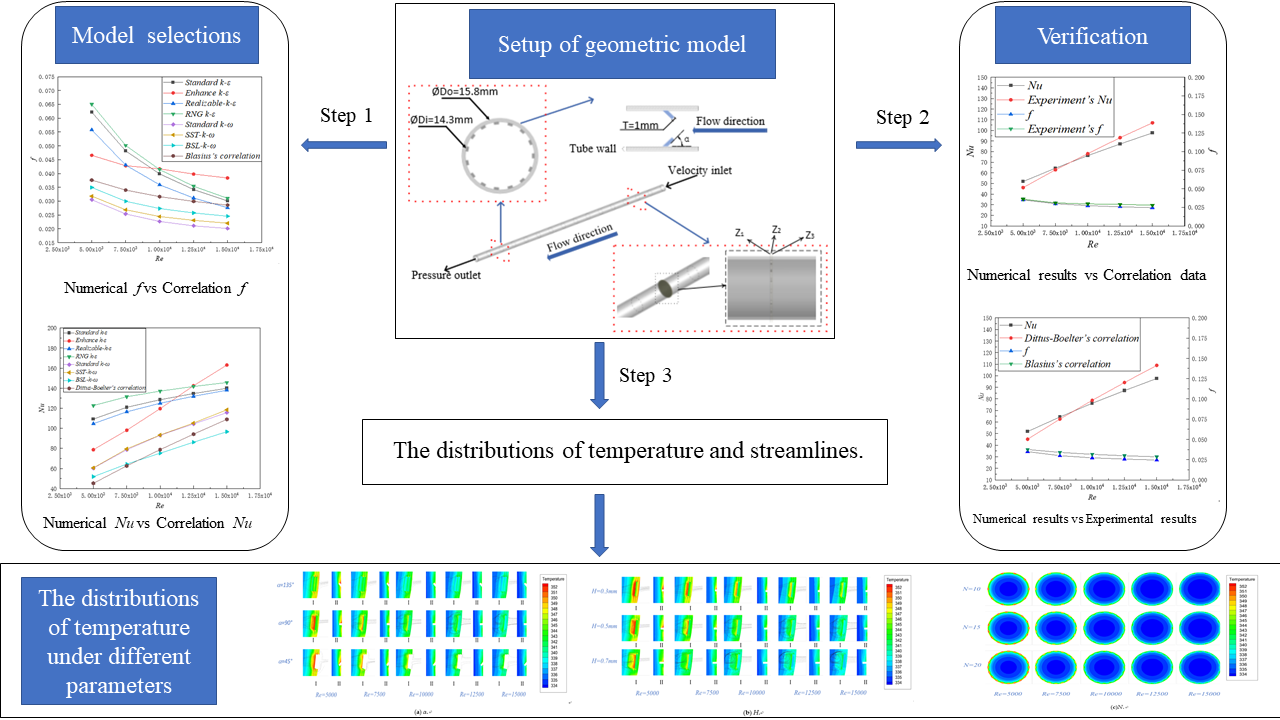
:The aim of this design was to improve the heat transfer performance significantly due to larger turbulent region and much vortices formed by tube inserted. In this article, the BSL k-ω model was chosen as turbulence model to simulate the thermohydraulic performance of the proposed tubes inserted with rectangular winglet vortex generators (RWVGs) when the Re was set as 5000 to 15,000. The reliability of the simulation results was obtained by comparing with the empirical formulas and experimental results. By means of numerical simulation, the influence mechanism of geometric parameters of RWVGs on thermal-hydraulic performance in tubes was analyzed. And the impact of three configurational parameters on the thermal performance was studied, namely the angle α, the height H and the number N of the RWVGs, respectively. The results revealed that the capacity of heat transfer in tubes with RWVG inserts was obviously larger than that in ordinary circular tube. In addition, it could be seen from the results that both Nu and f increased with the increase of H and N. At the same time, the case of α = 135° showed the greatest enhancement of thermal performance than the case of α = 45° and α = 90°.The PEC achieved the highest value of 1.23 when the height H of RWVG was 0.7 mm, the number N was 20, and angle α was 135°.

1. Introduction
Due to the good thermal conductivity and isothermal properties, heat exchange tubes, as one of the most common core heat exchange components, were usually applied in abundant industrial fields, such as heat recovery system, food production industry, energy utilization and so on. To pursue higher thermal performance, the application of enhanced heat transfer tubes in heat exchangers was the current development trend all over the world. Naturally, how to improve the heat transfer efficiency in tubes more reasonably and efficiently had become hot spot in recent days. In the past several decades, scholars had proposed a series of topics and surveys to enhance heat transfer in tubes.
At present, as to enhance tube’s thermal performance, three methods were adopted and classified [1]: active enhancement, passive enhancement and combined enhancement. After comprehensively comparing various heat exchange indexes and economy, experts preferred the passive type [2]. Among the passive enhancement methods, two types were most frequent. One was the tube inserted, which replaced the central fluid with the fluid near tube wall, such as twisted tape [3,4,5,6,7], twined coil [8,9], spiral coils [10], coiled wire [11,12], fin [13] baffle [14], wing/winglet [15,16,17], to adjust the distribution of velocity field and temperature field in the tube. The other one was the transformation of special-shaped pipe or pipe wall, which were mainly focused on the improvement of the boundary layer inside and outside the pipe wall [18,19,20,21,22].
Lots of researches were focused on the shaped tube, including triangle tube, square tube, oval tube, twisted oval tube and so on. Due to the special structure of shaped tube, the thermal performance could be obviously enhanced. Wang et al. [18] conducted a simulation to study the heat transfer mechanism of different arrangement of bellows on thermohydraulic performance of heat exchanger. It could be concluded that the thermal performance of the triangle tube arrangement was outstanding compared to the circle tube arrangement and square tube arrangement. Tan et al. [19] investigated the thermohydraulic performance of twisted oval tube. It could be obtained that both Nu and f were positively correlated to the twisted pitch length and aspect ratio. Talib et al. [20] studied the influence of spiral rectangular ribbed tube and found that the values of Nu in strengthened tubes were nearly 53% higher than that of the round tube. Hong et al. [21] conducted a numerical investigation and proposed a novel corrugated tube in tube heat exchangers. The results showed that the PEC reached the maximum value of 1.56 when the wavy corrugated tube was in parallel arrangement. Liu et al. [22] established a numerical model of rod-baffle heat exchanger fitted spirally corrugated tubes and investigated the effect of thermal performance under different starting frequencies. The results showed that four frequencies all had positive effect on the heat transfer performance of circular tubes. The PEC could reach the maximum value of 1.35 when frequency was set as one. Scholars had obtained satisfactory results in their study of shaped tubes and generally concluded that shaped tubes were conductive to enhance heat transfer inside the tubes.
And in terms of modification of tube wall, some articles [23,24,25] were generally concentrated on how to form vortices near tube wall by various configurations in heat exchange tubes and their results showed that longitudinal vortex generators (LVGs) and transverse vortex generators (TVGs) were in common. While, the thermal performance of the LVGs formed by the fluid in three-dimensional space was significantly better than that of the TVGs formed in two-dimensional space. Hence, LVGs were usually adopted in heat exchange tubes and a series of studies on LVGs had been produced. Sunil Chamoli et al. [26] studied the heat transfer and flow characteristics of a novel smooth tube with tori inserts through simulation. It can be obtained that the corresponding PEC of the novel tube varied from 0.94 to 1.42. Sompol Skullong [27] et al. experimentally investigated the thermal performance of tubular heat exchanger with louvered V-winglet (LVW) vortex generators inserts. The results showed that the highest thermo-hydraulic performance from the LVW was about 2.48 when the winglet pitches and angle were 1 and 30°,respectively. Habchi [28] numerically researched the thermal enhancement of heat transfer capacity in smooth tubes fitted rectangular wing VGs. The results revealed that the thermal performance of tubes with RWVG inserts was obviously better than that of ordinary tube and thermal enhancement could be increased by about 40%. Ali et al. [29] proposed a novel adjustable wing VG and conducted a numerical research. The simulation results showed that the thermal performance of the proposed tube was superior, compared with round tube and rigid VG’s tube. Zheng et al. [30] carried out a numerical study about the hydraulic performance of the heat exchanger tube fitted with discrete double inclined ribs. Due to the enhancement of fluid mixing by vortex, the results showed that the PEC were found to vary from 1.3 to 2.3. Later, they [31] numerically investigated the thermal performance of the novel internally grooved tube with multi-vortexes. It concluded that groove inclination angles had great effect on heat transfer performances and the minimum entropy generation number and maximum overall thermal-hydraulic performance were reached when the groove inclination angle was 30°. Besides, in order to improve the thermodynamic performance in the tube, Deshmukh et al. had done series of investigations. In 2014, Deshmukh et al. [32,33] took the lead in proposing a new structure of curved delta wing VG. The results showed that the ratio of average Nu with and without the insert was in the range of 1.3–5.0. In Aliabadi’s paper [34], it was also confirmed that insert VG would increase the heat transfer area and energy loss, and the value of PEC could reach the peak at 1.41 when Re was 8715. It was not difficult to perceive from previous studies that modifications of tube wall also played a positive role in the enhancement of thermal-hydraulic performance and the VGs inserted in tube became research hotspots. Also, the nanofluid was applied further to enhance the heat transfer performance. In 2015, Aliabadi [35] tried to use nanofluids instead of traditional working fluids. The final results showed that PEC increased by about 228.5%. Furthermore, in 2016, the effect of dilute Cu–water nanofluid flow on the thermal performance of tubular heat exchangers was modified and studied in the follow-up work by Aliabadi’s research group [36]. The results showed that the maximum PEC of 1.83 was obtained with the Cu–water nanofluid when the winglets-width ratio was 0.6.
Combined the mentioned previous studies above, it could obtain that winglet vortex generators had obviously beneficial to thermodynamic performance in the heat exchange tubes. However, the improvement of heat transfer performance was often accompanied by the increase of pressure drop in previous works. In order to optimize the synergistic effect between the thermal performance and the energy loss to obtain low resistance and efficient heat transfer performance, the present work came up with a novel tube inserted with rectangular winglet vortex generators (RWVGs). Considering that the main thermal resistance of convective heat transfer was concentrated near the wall [37], RWVGs in the tube were mainly distributed on the tube wall in a discrete manner.
As known, though the laminar flow near the tube wall was thin, its effect on the thermal performance was negative and tremendous. On the one hand, the RWVGs, promoted in this paper, could enhance the turbulence intensity near the tube wall which was the main heat exchange area. On the other hand, large vortex generators could lead in large pressure drop. Therefore, the small RWVGs were proposed in this paper to improve the thermal performance at little cost of energy. Its purpose was to generate multiple longitudinal vortices in the boundary layer without causing a significant increase in pressure drop, which was also conducive to the enhancement of heat transfer performance in the tube. Hence, the angle and the number of the RWVGs should be considered. Besides, in order to control the pressure drop, height was also an necessary factor to investigate. The main research purposes of this paper included: (1) Analysis of thermohydraulic performance in tubes with RWVG inserts; (2) The effects of different geometric parameters (such as the winglets’ height, the angle and the number of the winglets in a circle) on thermohydraulic performance in tubes with RWVG inserts was analyzed and the interaction between geometric parameters had been discussed. (3) Through the temperature and streamlines distribution of the simulation results, the mechanism of heat transfer and flow resistance in the ribbed tube with RWVGs was obtained. Among them, all the work was conducted when the Reynolds number was between 5000 and 15,000.
2. Methodology
2.1. Geometry of the Model
In order to study the effect of rectangular winglet vortex generators (RWVGs) attached to the inner surface of circular tubes on heat transfer performance, the tube with RWVGs inserts had been revealed in Figure 1. The model of the novel tube was mainly composed of three parts: inlet section, outlet section and test section. The length of inlet section and outlet section was 100 mm and 250 mm, respectively. Among of these three sections, the diameter kept constant. RWVGs were arranged on the inner wall of the pipe circumferentially, the specific parameters of RWVGs and the proposed tube were presented in Table 1.
2.2. Mathematical Modeling
Before calculating the above model, the following assumptions were put forward: (1) The working fluid in the tube was incompressible fluid without phase transition; (2) The physical parameters of the working fluid were constant. (3) Thermal radiation was negligible.
The governing equations of the turbulence model were presented as follows:
Continuity equation:
Momentum equation:
Energy equation:
2.3. BSL k-ω Model
BSL k-ω model was developed by Menter [38]. Compared with the standard model, the BSL model also took the damping cross diffusion derivative into account, and the correlation constants were not exactly the same.
The Transport Equations for the BSL k-ω Model:
And
The effective diffusivities equations for the BSL k-ω model were as follows:
where and were the turbulent Prandtl numbers for k and ω, respectively, while noted that in the high-Reynolds number form of the k-ω model.
and represented the dissipation of k and ω due to turbulence, calculated as
What needed to be noted was: For the BSL k-ω model, the values of and constantly were 1, represented the cross-diffusion term, calculated as:
The blending function was given by
where y referred to the distance between the current surface and the next surface, represented the positive part of the diffusion term when the two intersected.
andwere user-defined source terms. and accounted for buoyancy terms. , .
All other relevant parameters in fixed value (, ,, , , ,, , and) were the same as those of the standard k-ω model.
2.4. Boundary Conditions
The boundary conditions before calculation were set as follows:
The boundary conditions of inlet section:
The boundary conditions of outlet section:
Wall boundary conditions:
Thermo-physical properties of water were shown in Table 2. The ANSYS Fluent software was used to solve the governing equations under the given boundary conditions, and its solution method was mainly based on finite volume method (FVM). The velocity–pressure coupling was calculated by coupled algorithm. Momentum and energy equations were solved by second-order upwind scheme. The turbulent kinetic energy and specific dissipation rate equations were settled by first order upwind. In addition, the continuity equation was set as 10−6 while the energy equation was set as 10−6.
3. Data Reduction and Validation
3.1. Data Reduction
Nu (Nusselt number) and f (f factor) [39], as important indexes to measure thermohydraulic performance, were expressed as
where D represents the hydraulic diameter, here was the inner diameter of the pipe Di. The mathematical expression of the average temperature and pressure of the cross section was given as:
Mathematical expressions of pressure drop , heat transfer capacity Q, logarithmic average temperature difference and heat transfer coefficient h were given as:
3.2. Mathematical Modeling Selection
In this study, all the simulation models, including k-ε models (Standard, RNG, and Realizable) and k-ω models (Standard, BSL and SST), were used to discuss the thermohydraulic performance in smooth circular tubes. The present simulation results were also compared with the empirical formulas [42], revealed in Figure 2. It can be observed from the Figure 2a that the results of f calculated by BSL k-ω model were the closest and consistent with Blasius’s correlation in this paper. What’s more, the average errors about Nu between simulation results and empirical formula were 18.2% (standard k-ω), 19.8% (SST k-ω) and 7.6% (BSL k-ω), seen in Figure 2b. Hence, the BSL k-ω model was chosen as turbulence model in the RWVGs’ tube due to its outstanding accuracy.
3.3. Mesh Independence
Good mesh was helpful for the numerical simulation of inserted tube by CFD solver and ensured the thermohydraulic performance in tube more reliable. The mesh methods adopted in this paper composed of unstructured mesh and structured mesh. The structured mesh was adopted in the computing domain, while the inlet section and the outlet section were discretized by unstructured elements. Figure 3 revealed the specific grid division. In order to improve the accuracy as possible, the grids on the tube wall and surface of RWVGs were locally densified. Five different grid numbers had been performed in the grid independent tests at Re = 5000. According to the variation range of Nu and f, the optimal number of grids could be inferred. As the elements of grids increased, it could be obtained from the Table 3 that the deviations of Nu and f became smaller. It can be noted that the deviations of Nu and f were tend to be constant when the element number reached 11,277,684. The proper grid system could not only avoid large calculation time, but also ensured accuracy of the simulation. Finally, the grid numbers with 11,277,684 was selected for follow-up investigation.
The velocity and thermal boundary layers could be captured by mesh to obtain the most reliable mesh. According to the requirements of fluent user guide, the value of dimensionless y+ parameter was less than 1 [43]. Therefore, the local convection coefficient and Nusselt number could be used as reference values to reflect the capture ability of the grid through the change of the grids number. The corresponding experiments showed that they tend to be constant with the increase of the number of grids.
3.4. Validation
By comparing the calculated results of Nu and f with the empirical formulas proposed by predecessors, the formula of Dittus-Boelter which used to predict for Nu was as follow:
Similarly, the simulation results of f were compared with the results calculated by Blasius’s empirical formula. The formula of Blasius which used to predict for f was as follow:
for .
Both Dittus-Boelter’s correlation and Blasius’s correlation were obtained from the literature for turbulent flow in duct [42].
Figure 4a simultaneously showed the comparison of the simulated Nu and f in present work with the results calculated by Dittus-Boelter’s formula and Blasius’s formula, respectively. In order to compare and analyze the reliability of simulation results more intuitively, the relative errors of Nu and f between simulation research and calculated values were defined as the percentage errors. As seen in Figure 4a, the percentage error of Nu was relatively small, and the accurate value was only ±7.66%. The f obtained in the present work had good agreement with Blasius’s formula (Equation (25)). The value of percentage error was within ±12.11%. The percentage errors of Nu and f were both less than 13%, and these errors might be caused by the uncertainty of calculation parameters. Hence, it could be determined that the simulation results for the circular tube were highly consistent with the results calculated by the empirical formula.
In order to make the simulation results more compelling, some experiment results of tube with RWVG inserts in Ref. [44] were also used to verify. Figure 4b displayed the comparison between simulated results and experimental results. As seen in Figure 4b, the percentage error of Nu was ±6.45%. The simulated f also matched with the experimental result and the value of percentage error was ±7.42%. Therefore, it further showed that the simulation technique and results in this paper were reasonable and reliable.
4. Result and Discussion
As the main research object of this paper, rectangular-winglet vortex generators could enhance the thermohydraulic performance in the tube by adjusting the flow direction of working fluid in the tube. As known, the essential difference between laminar flow and turbulent flow was that there was no radial pulsation in the fluid particles of the former. While the radial pulsation in turbulent flow led great turbulence, having positive influence on thermal performance. However, intense collision in the particles would inevitably lead the increasing of energy loss. In many studies, increasing turbulence was the key point to enhance thermohydraulic performance.
In this section, the temperature and streamlines distributions in circular tube and RWVG-inserted tube were obtained after being solved by FLUENT software. Moreover, the present works were mainly considered from three factors: The angle α, the height H and the number N of the RWVGs in a circle, respectively. The range of investigated Re number was between 5000 and 15,000.
4.1. Analysis of Influence of RWVGs
The temperature and streamline distribution in the tube with RWVG inserts were essential for the study and analysis of heat transfer mechanism. As shown in Figure 1, in order to analyze the effect of RWVGs on thermohydraulic performance in the tube more intuitively, this section would conduct the comparative analysis in three different cross sections with streamlines and temperature contour, namely Z1 = 69.85 mm, Z2 = 70.00 mm and Z3 = 70.15 mm, respectively. Those three cross sections were respectively defined as the regions before VGs, beside VGs and behind VGs.
Figure 5aI presented the temperature and streamlines distributions in different types (α = 45°, α = 90°, α = 135°) of tubes under five different Reynolds numbers. With the increase of Reynolds number, the flow velocity of working fluid increased, leading an increase of turbulence and a thinner heat transfer boundary layer, decreasing the heat transfer resistance. It was easy to observe a gradual decrease of the temperature in the region around VGs as the Reynolds number increased. Besides, the flow streamlines indicated that when the air struck the wall at high speed, the fluid would form smaller vortices at the front of the VGs and then the air swept along the edge of VGs, forming larger vortices at the back of VGs. Vortices made the fluid radial movement between the tube wall and the core flow region more violent, which also led a better fluid turbulence and a greater thermal performance in the tube with VGs inserts. And when the Re number remained constant, it could be judged that the heat transfer capacity of α = 135° was better than that of α = 90° and α = 45°according to the temperature distribution. As was shown in Figure 5II, longitudinal comparative analysis could be obtained that the local temperature of the rear area of VGs was significantly higher than that of the front area when the value of Reynolds numbers was 5000 to 7500.
Revealed in Figure 5bI, it showed that two vortices were generated when the working fluid flew through a VG. Two vortices were both located in the back of the VG. When air struck the surface of VG, the increase in flow velocity led to increased divergence of spiral streamlines, then the intensity of turbulence had been significantly improved, it was undoubtedly beneficial to the heat transfer enhancement in the tube. Figure 5bII showed that the local temperature around RWVGs was relatively high due to the configuration of RWVGs, while, as the Reynolds number increased, the temperature distribution gradually became uniform in the tube with RWVG inserts. From a vertical perspective, due to the increase of height H, the high temperature region near RWVGs became significantly smaller when the value of Reynolds numbers was between 5000 to 7500.
As shown in Figure 5c, the temperature field distribution in the tube was relatively uniform no matter what the value of N was. It was not difficult to distinguish that the temperature around the RWVGs was the highest in the tube.
The distributions of the local wall heat transfer coefficient were displayed in Figure 6. It was not difficult to obtain from the figure that the heat transfer coefficient of VGs surface area was much greater than that of other areas. The main reason for this phenomenon was that the surface of VGs was directly crashed by the fluid in the pipe. In addition, the heat transfer coefficient at the rear region of VGs was relatively high, and the strong vortex intensity would form the vortex in this area.
4.2. Effect of Geometric Parameters
4.2.1. Effect of the RWVG Angle
Figure 7 compared the thermohydraulic performance of ordinary circular tube and smooth tubes with RWVGs (α = 45°, α = 90°, α = 135°). Figure 7a showed the relationship between Re and Nu in circular tube and tubes with RWVG inserts. It can be clearly seen from Figure 7a that the trends of Nu change in circular tube and RWVG inserted tubes were almost the same. In addition, the Nu of three different RWVG inserted tubes were much larger than that of ordinary circular tube under the same Reynolds number. This directly reflected that the RWVG inserts greatly enhanced the heat transfer performance in the circular tube. What’s more, as the Figure 7a showed, with the increase of Re, the deviations of Nu between tubes with RWVG inserts and plain tube became larger and larger when the range of Reynolds number was less than 7500. However, this trend was not obvious when the value was more than 7500.
Figure 7b showed the relationship between f and Re of three kinds of RWVG inserted tubes (α = 45°, α = 90°, α = 135°) and circular tube. In general, the trend of f in RWVG inserted tubes (α = 45°, α = 90°, α = 135°) and ordinary circular tube were roughly the same. Generally, the values of f gradually decreased as the Re increased. And in details, as the Re increased, the downward trend of the f values became more and more gentle. Similarly to the Nu, the f of tubes with RWVG inserts (α = 45°, α = 90°, α = 135°) were significantly greater than that of circular tube under the same Reynolds number. And with the increase of Re, the difference of f between tube with RWVG inserts and circular tube became larger and larger.
4.2.2. Effect of the RWVG Height
In order to investigate the effects of RWVG inserts on thermo-hydraulic characteristics of flow in smooth tubes, Nu and f were plotted in Figure 8 for a range of height H. Similar to the line distribution of Figure 8a, the Nusselt number was almost proportional to the Re in all the cases. The increase of Nu could be proved that the enhancement of heat transfer had been achieved in all the cases with different height under the same Re. Furthermore, it could be clearly found that Nusselt number has little change when the height of RWVGs was 0.3 mm, however, when the value of H was 0.5 mm or 0.7 mm, the increase in heat transfer performance of the tubes were undoubtedly considerable. And the best performance of heat transfer could be obtained when the value of H was 0.7 mm in this paper.
Relationship between f factor and Re of tube with RWVG inserts and circular tube had been shown in Figure 8b. The height H had a greater influence on thermohydraulic performance than the angle α under the same Reynold number. Compared with the result of the plain tube, the increase rate of the friction factors was 2.755% (H = 0.3 mm), 10.531% (H = 0.5 mm) and 25.738% (H = 0.7 mm) respectively when the Re was set as 5000. With the increase of the Re, the increasing rate could even reach 6.291% (H = 0.3 mm), 23.177% (H = 0.5 mm) and 51.668% (H = 0.7 mm) respectively when the Re was set as 15,000. This phenomenon was due to the great effect of the height diversification on the formation process of turbulence.
4.2.3. Effect of the RWVG Number in a Circle
Figure 9 generally presented the thermal performance of the plain tube and tube inserted with different numbers of RWVG in a circle. Except that the overall trend is almost the same as the above analysis, it could be clearly seen that the changes between adjacent curves were evenly distributed in Figure 9a. Compared Figure 9a,b, it could be found that the gaps of f were fairly larger than that of Nu at the same Reynolds number. In details, the gaps increased when the Re increased in the range of 5000 to 15,000. In general, both Nu and f increased with the increase of N, the reason for this phenomenon could be speculated as: the enhancement of heat transfer around the RWVGs was greater than that of further region and the increase of the number N would make the external region of RWVGs more expanded.
4.3. Analyze the Influence of RWVGs on Comprehensive Performance
Webb et al. [40] proposed a method to evaluate the performance improvement of strengthened tubes compared with smooth tubes of the same diameter. This method evaluated the performance from the perspective of energy balance. PEC, a performance evaluation index in convective heat transfer process, was generally obtained at the cost of flow resistance ratio and the benefit of heat transfer ratio between strengthened tube and smooth tube. Therefore, PEC should be considered in this section.
On the basis of the previous analysis, Figure 10 illustrated the variation in the PEC values of the tube with RWVG inserts. It was not difficult to obtain a better thermal performance in the tube when the Re was less than 7500 and the PEC values vary between 1.10 to 1.23. As shown in Figure 10a, the tube with RWVG inserts achieved the most ideal thermal performance when the value of α was 135° in this paper. In addition, Figure 10b showed that, when the height H was less than 0.5, the PEC increased; However, when the height H was greater than 0.5, the change of PEC was relatively small, and there would even be a downward trend under the condition of high Reynolds number. So H = 0.5 mm was recommended for practical applications when considered the comprehensive performance in this paper. In this case, PEC had not changed much under the same Reynolds number, as seen in Figure 10c.
According to the analysis above, the height H was beneficial to Nu but the flow resistance in the pipe greatly increased as well. It can be inferred that excessive windward area would result in poor comprehensive performance in the pipe. Due to the high heat transfer coefficient at the rear region of VGs and the vortex formed by α = 135° was closer to the tube wall than that formed by α = 45°, α = 135° had a more significant effect on the heat transfer in the tube. As for number N, the proportions of Nu and f increasing with the increase of N were close, so PEC had no obvious change. Therefore, α = 135° and H = 0.5 mm were still recommended based on the research of this paper.
4.4. Comparison with Previous Work
In this section, four representative enhanced heat exchange tubes were selected to compare with the RWVG inserted tubes proposed in this paper. As shown in the Figure 11, the four kinds of enhanced heat exchange tubes were internally finned tube [45], transversally grooved tube [46], short-length twisted tape inserted tube [47] and coiled square wires inserted tube [48], respectively. In terms of overall trends, it was evident that the thermal performance of the tube continued to increase as the Reynolds number decreased. The result implied that the heat exchange tube proposed in this article had the prospect of practical application and could be further studied in the future under the condition of low Reynolds number and different parameter variables.
5. Conclusions
In this paper, the thermohydraulic performance in the tubes with RWVGs inserted were numerically simulated when the Re was set as 5000 to 15,000. The main contents included: the effects of the changes of three geometric parameters (height H, angle α and number N of the RWVGs) of tubes with RWVGs inserted on the thermohydraulic performance in proposed tubes and the comparative analysis with ordinary circular tubes under five different Re (Re = 5000, 7500, 10,000, 12,500, 15,000). According to the results obtained, the following conclusions could be summarized:
- (1)
- For the range of Reynolds numbers investigated, both Nu and f increased with the increased of H and N, and the percentage increase of the Nusselt number was about 9.7% and 7.3%. At the same time, the case of α = 135° showed the greatest enhancement of thermal performance than the case of α = 45° and α = 90°. The percentage increase of the Nusselt number could reach 7%.
- (2)
- Vortices made the radial movement of the fluid between the tube wall and the core flow region more violent, which also led a better fluid turbulence and a greater thermal performance in the tube inserted with VGs.
- (3)
- The three variables mentioned above had influence on the thermal performance in the tube with RWVGs inserted. It was found that angle was the factor that had the greatest impact on the thermal performance among the studied parameters. The results showed that the maximum value of PEC under the three angles was 1.211, while the PEC of the number N and the height H was of 1.201 and 1.199, respectively.
- (4)
- The PEC achieved the highest value of 1.23 when the height H of the RWVG was 0.7 mm, the number N was 20, and the angle α was 135°.
6. Highlights
- The ribbed tube with novel RWVGs is proposed for heat transfer enhancement.
- The BSL k-ω model is employed owing to better accuracy in the tube with the proposed RWVGs.
- Details of the flow structures and temperature distributions in the ribbed tube are presented and analyzed.
- Effects of geometric parameters on thermal-hydraulic characteristics are examined and optimum parameters for the ribbed tube with RWVGs are reported for practical applications.
Author Contributions
Conceptualization, Y.L., Z.Q. and Q.W.; software, Y.L. and Q.W.; validation, Y.L. and Q.W.; Resources and data, Y.L. and Q.W.; writing-original draft preparation, Y.L. and Wang Qiang; writing-review and editing, Y.L. and Q.W.; supervision, Z.Q.; project administration, Z.Q.; funding acquisition, Z.Q. All authors have read and agreed to the published version of the manuscript.
Funding
This research received no external funding.
Institutional Review Board Statement
Not applicable.
Informed Consent Statement
Not applicable.
Data Availability Statement
Not applicable.
Conflicts of Interest
The authors declare no conflict of interest.
Nomenclature
| The area of heated wall () | |
| The heat capacity of working fluid () | |
| The hydraulic diameter () | |
| The friction factor | |
| The mass flow of working fluid () | |
| () | |
| The turbulence intensity | |
| k | Turbulent kinetic energy () |
| The length of flow direction () | |
| The Nusselt number | |
| P | () |
| Performance evaluation criterion | |
| Prandtl number | |
| The total rate of heat transfer () | |
| The Reynolds number | |
| The temperature of the outlet () | |
| The temperature of the inlet () | |
| The temperature of wall () | |
| Temperature of the working fluid () | |
| T () | |
| T () | |
| T () | |
| T () | |
| Volume of working fluid () |
Greek Symbols
| The pressure drops between the inlet and outlet () | |
| () | |
| Dissipation rate of turbulent kinetic energy of the k- model () | |
| () | |
| Dynamic viscosity () | |
| Kinematic viscosity () | |
| Density of working fluid () |
Subscripts
References
- Sheikholeslami, M.; Gorji-Bandpy, M.; Ganji, D.D. Review of heat transfer enhancement methods: Focus on passive methods using swirl flow devices. Renew. Sustain. Energy Rev. 2015, 49, 444–469. [Google Scholar] [CrossRef]
- Liu, S.; Sakr, M. A comprehensive review on passive heat transfer enhancements in pipe exchangers. Renew. Sustain. Energy Rev. 2013, 19, 64–81. [Google Scholar] [CrossRef]
- Eiamsa-ard, S.; Changcharoen, W.; Beigzadeh, R.; Eiamsa-ard, P.; Wongcharee, K.; Chuwattanakul, V. Influence of co/counter arrangements of multiple twisted-tape bundles on heat transfer intensification. Chem. Eng. Process.-Process Intensif. 2021, 160, 108304. [Google Scholar] [CrossRef]
- Manglik, R.; Bergles, A. Heat transfer and pressure drop correlations for twisted-tape inserts in isothermal tubes: Part I—laminar flows. Trans.-Am. Soc. Mech. Eng. J. Heat Transf. 1993, 115, 881–889. [Google Scholar] [CrossRef]
- Manglik, R.M.; Bergles, A.E. Heat transfer and pressure drop correlations for twisted-tape inserts in isothermal tubes: Part II—Transition and turbulent flow. J. Heat Transf. 1993, 115, 890–896. [Google Scholar] [CrossRef]
- Saha, S.K.; Dutta, A.; Dhal, S.K. Friction and heat transfer characteristics of laminar swirl flow through a circular tube fitted with regularly spaced twisted-tape elements. Int. J. Heat Mass Transf. 2001, 44, 4211–4223. [Google Scholar] [CrossRef]
- Wongcharee, K.; Eiamsa-Ard, S. Friction and heat transfer characteristics of laminar swirl flow through the round tubes inserted with alternate clockwise and counter-clockwise twisted-tapes. Int. Commun. Heat Mass Transf. 2011, 38, 348–352. [Google Scholar] [CrossRef]
- Dang, W.; Wang, L. Convective heat transfer enhancement mechanisms in circular tube inserted with a type of twined coil. Int. J. Heat Mass Transf. 2021, 169, 120960. [Google Scholar] [CrossRef]
- Sharifi, K.; Sabet, M.; Rafiei, M.; Mohammadi, A.H.; Ghaffari, A.; Asl, M.H.; Yousefi, H. A good contribution of computational fluid dynamics (CFD) and GA-ANN methods to find the best type of helical wire inserted tube in heat exchangers. Int. J. Therm. Sci. 2020, 154, 106398. [Google Scholar] [CrossRef]
- Chiou, J. Experimental investigation of the augmentation of forced convection heat transfer in a circular tube using spiral spring inserts. J. Heat Transf. 1987, 109, 300–307. [Google Scholar] [CrossRef]
- Yu, C.; Zhang, H.; Youqiang Wang, M.Z.; Gao, B. Numerical study on turbulent heat transfer performance of twisted oval tube with different cross sectioned wire coil. Case Stud. Therm. Eng. 2020, 22, 100759. [Google Scholar] [CrossRef]
- Keklikcioglu, O.; Ozceyhan, V. Entropy generation analysis for a circular tube with equilateral triangle cross sectioned coiled-wire inserts. Energy 2017, 139, 65–75. [Google Scholar] [CrossRef]
- Promvonge, P.; Skullong, S.; Kwankaomeng, S.; Thiangpong, C. Heat transfer in square duct fitted diagonally with angle-finned tape—Part 1: Experimental study. Int. Commun. Heat Mass Transf. 2012, 39, 617–624. [Google Scholar] [CrossRef]
- Tandiroglu, A. Effect of flow geometry parameters on transient heat transfer for turbulent flow in a circular tube with baffle inserts. Int. J. Heat Mass Transf. 2006, 49, 1559–1567. [Google Scholar] [CrossRef]
- Liou, T.; Chen, C.; Wang, C.; Wang, E. Thermal-fluidic correlations for turbulent flow in a serpentine heat exchanger with novel wing-shaped turbulators. Int. J. Heat Mass Transf. 2020, 160, 120220. [Google Scholar] [CrossRef]
- Skullong, S.; Promvonge, P.; Thianpong, C.; Jayranaiwachira, N. Thermal behaviors in a round tube equipped with quadruple perforated-delta-winglet pairs. Appl. Therm. Eng. 2017, 115, 229–243. [Google Scholar] [CrossRef]
- Promvonge, P.; Skullong, S. Thermo-hydraulic performance in heat exchanger tube with V-shaped winglet vortex generator. Appl. Therm. Eng. 2020, 164, 114424. [Google Scholar] [CrossRef]
- Wang, W.; Shuai, Y.; Ding, L.; Li, B.; Sundén, B. Investigation of complex flow and heat transfer mechanism in multi-tube heat exchanger with different arrangement corrugated tube. Int. J. Therm. Sci. 2021, 167, 107010. [Google Scholar] [CrossRef]
- Tan, X.-H.; Zhu, D.-S.; Zhou, G.-Y.; Yang, L. 3D numerical simulation on the shell side heat transfer and pressure drop performances of twisted oval tube heat exchanger. Int. J. Heat Mass Transf. 2013, 65, 244–253. [Google Scholar] [CrossRef]
- Talib, R.N.; Yasin, N.J.; Nasser, M.A. The effect of external helical ribs tube on the heat transfer and pressure drop performance for multi-tube heat exchanger. IOP Conf. Ser. Mater. Sci. Eng. 2019, 518, 032015. [Google Scholar] [CrossRef]
- Hong, Y.; Du, J.; Wang, S.; Huang, S. Heat transfer and flow behaviors of a wavy corrugated tube. Appl. Therm. Eng. 2017, 126, 151–166. [Google Scholar] [CrossRef]
- Liu, J.J.; Liu, Z.C.; Liu, W. 3D numerical study on shell side heat transfer and flow characteristics of rod-baffle heat exchangers with spirally corrugated tubes. Int. J. Therm. Sci. 2015, 89, 34–42. [Google Scholar] [CrossRef]
- Jia, H.; Liu, W.; Liu, Z. Enhancing convective heat transfer based on minimum power consumption principle. Chem. Eng. Sci. 2012, 69, 225–230. [Google Scholar] [CrossRef]
- Liu, W.; Jia, H.; Liu, Z.C.; Fang, H.S.; Yang, K. The approach of minimum heat consumption and its applications in convective heat transfer optimization. Int. J. Heat Mass Transf. 2013, 57, 389–396. [Google Scholar] [CrossRef]
- Jia, H.; Liu, Z.C.; Liu, W.; Nakayama, A. Convective heat transfer optimization based on minimum entransy dissipation in the circular tube. Int. J. Heat Mass Transf. 2014, 73, 124–129. [Google Scholar] [CrossRef]
- Chamoli, S.; Zhuang, X.; Pant, P.K.; Yu, P. Heat transfer in a turbulent flow tube integrated with tori as vortex generator inserts. Appl. Therm. Eng. 2021, 194, 117062. [Google Scholar] [CrossRef]
- Promvonge, P.; Promthaisong, P.; Skullong, S. Thermal performance augmentation in round tube with louvered V-winglet vortex generator. Int. J. Heat Mass Transf. 2022, 182, 121913. [Google Scholar] [CrossRef]
- Habchi, C.; Harion, J.-L. Residence time distribution and heat transfer in circular pipe fitted with longitudinal rectangular wings. Int. J. Heat Mass Transf. 2014, 74, 13–24. [Google Scholar] [CrossRef]
- Ali, S.; Habchi, C.; Menanteau, S.; Lemenand, T.; Harion, J.-L. Three-dimensional numerical study of heat transfer and mixing enhancement in a circular pipe using self-sustained oscillating flexible vorticity generators. Chem. Eng. Sci. 2017, 162, 152–174. [Google Scholar] [CrossRef]
- Zheng, N.; Liu, W.; Liu, Z.; Liu, P.; Shan, F. A numerical study on heat transfer enhancement and the flow structure in a heat exchanger tube with discrete double inclined ribs. Appl. Therm. Eng. 2015, 90, 232–241. [Google Scholar] [CrossRef]
- Zheng, N.; Liu, P.; Shan, F.; Liu, Z.; Liu, W. Heat transfer enhancement in a novel internally grooved tube by generating longitudinal swirl flows with multi-vortexes. Appl. Therm. Eng. 2016, 95, 421–432. [Google Scholar] [CrossRef]
- Deshmukh, P.W.; Vedula, R.P. Heat transfer and friction factor characteristics of turbulent flow through a circular tube fitted with vortex generator inserts. Int. J. Heat Mass Transf. 2014, 79, 551–560. [Google Scholar] [CrossRef]
- Deshmukh, P.W.; Prabhu, S.V.; Vedula, R.P. Heat transfer enhancement for laminar flow in tubes using curved delta wing vortex generator inserts. Appl. Therm. Eng. 2016, 106, 1415–1426. [Google Scholar] [CrossRef]
- Khoshvaght-Aliabadi, M.; Sartipzadeh, O.; Alizadeh, A. An experimental study on vortex-generator insert with different arrangements of delta-winglets. Energy 2015, 82, 629–639. [Google Scholar] [CrossRef]
- Khoshvaght-Aliabadi, M.; Shabanpour, H.; Alizadeh, A.; Sartipzadeh, O. Experimental assessment of different inserts inside straight tubes: Nanofluid as working media. Chem. Eng. Process. Process Intensif. 2015, 97, 1–11. [Google Scholar] [CrossRef]
- Khoshvaght-Aliabadi, M.; Akbari, M.H.; Hormozi, F. An empirical study on vortex-generator insert fitted in tubular heat exchangers with dilute Cu–water nanofluid flow. Chin. J. Chem. Eng. 2016, 24, 728–736. [Google Scholar] [CrossRef]
- Sun, Z.; Chen, Q.; Zheng, N. Experimental and numerical studies of intensified turbulent heat transfer in round pipes with curved wing vortex generators. Int. J. Heat Mass Transf. 2021, 180, 121823. [Google Scholar] [CrossRef]
- Menter, F.R. Two-Equation Eddy-Viscosity Turbulence Models for Engineering Applications. AIAA J. 1994, 32, 1598–1605. [Google Scholar] [CrossRef] [Green Version]
- Bharadwaj, P.; Khondge, A.D.; Date, A.W. Heat transfer and pressure drop in a spirally grooved tube with twisted tape insert. Int. J. Heat Mass Transf. 2009, 52, 1938–1944. [Google Scholar] [CrossRef]
- Webb, R. Performance evaluation criteria for use of enhanced heat transfer surfaces in heat exchanger design. Int. J. Heat Mass Transf. 1981, 24, 715–726. [Google Scholar] [CrossRef]
- Cheraghi, M.H.; Ameri, M.; Shahabadi, M. Numerical study on the heat transfer enhancement and pressure drop inside deep dimpled tubes. Int. J. Heat Mass Transf. 2020, 147, 118845. [Google Scholar] [CrossRef]
- Fluent; Version 6; ANSYS Inc.: Canonsburg, PA, USA, 2009.
- Bergman, T.L.; Incropera, F.P.; Lavine, A.S.; Dewitt, D.P. Introduction to Heat Transfer; John Wiley & Sons: Hoboken, NJ, USA, 2011. [Google Scholar]
- Zhang, K.; Sun, Z.; Zheng, N.; Chen, Q. Effects of the configuration of winglet vortex generators on turbulent heat transfer enhancement in circular tubes. Int. J. Heat Mass Transf. 2020, 157, 119928. [Google Scholar] [CrossRef]
- Wang, Q.W.; Lin, M.; Zeng, M. Effect of lateral fin profiles on turbulent flow and heat transfer performance of internally finned tubes. Appl. Therm. Eng. 2009, 29, 3006–3013. [Google Scholar] [CrossRef]
- Bilen, K.; Cetin, M.; Gul, H.; Balta, T. The investigation of groove geometry effect on heat transfer for internally grooved tubes. Appl. Therm. Eng. 2009, 29, 753–761. [Google Scholar] [CrossRef]
- Eiamsa-ard, S.; Thianpong, C.; Eiamsa-ard, P.; Promvonge, P. Convective heat transfer in a circular tube with short-length twisted tape insert. Int. Commun. Heat Mass Transf. 2009, 36, 365–371. [Google Scholar] [CrossRef]
- Promvonge, P. Thermal performance in circular tube fitted with coiled square wires. Energy Convers. Manag. 2008, 49, 980–987. [Google Scholar] [CrossRef]
Figure 1.
Detail view of the circular tube inserted with RWVGs and the locations of three cross-sections.
Figure 1.
Detail view of the circular tube inserted with RWVGs and the locations of three cross-sections.

Figure 2.
Verifications between numerical results and correlation data: (a) Verifications of f; (b) Verifications of Nu.
Figure 2.
Verifications between numerical results and correlation data: (a) Verifications of f; (b) Verifications of Nu.


Figure 3.
Grids generated for computation domain.

Figure 4.
Verifications: (a) Numerical results vs. Correlation data; (b) Numerical results vs. Experimental results.
Figure 4.
Verifications: (a) Numerical results vs. Correlation data; (b) Numerical results vs. Experimental results.


Figure 5.
The fluid temperature and streamlines distribution of inserted tubes under different geometrical parameters. (a) α, (b) H, (c) N.
Figure 5.
The fluid temperature and streamlines distribution of inserted tubes under different geometrical parameters. (a) α, (b) H, (c) N.


Figure 6.
Local wall heat transfer coefficient contours on the wall of the tube.

Figure 7.
Comparison of heat transfer and flow resistance between plain tube and smooth tube with RWVGs in different α. (a) Nu, (b) f.
Figure 7.
Comparison of heat transfer and flow resistance between plain tube and smooth tube with RWVGs in different α. (a) Nu, (b) f.


Figure 8.
Comparison of heat transfer and flow resistance between plain tube and smooth tube with RWVGs in different H. (a) Nu, (b) f.
Figure 8.
Comparison of heat transfer and flow resistance between plain tube and smooth tube with RWVGs in different H. (a) Nu, (b) f.

Figure 9.
Comparison of heat transfer and flow resistance between plain tube and smooth tube with RWVGs in different N. (a) Nu, (b) f.
Figure 9.
Comparison of heat transfer and flow resistance between plain tube and smooth tube with RWVGs in different N. (a) Nu, (b) f.


Figure 10.
Effect of different factors on heat transfer and flow performance: (a) the angle α, (b) the height H, (c) the number N.
Figure 10.
Effect of different factors on heat transfer and flow performance: (a) the angle α, (b) the height H, (c) the number N.


Figure 11.
Comparisons with previous work.


Table 1.
Geometrical structures and parameters used during numerical studies.
| Tube Parameters | Unit | Value |
|---|---|---|
| Inner diameter of the tube (Di) | mm | 14.3 |
| Outer diameter of the tube (Do) | mm | 15.8 |
| Tube length (L) | mm | 814 |
| RWVGs geometry | ||
| Height (H) | mm | 0.3, 0.5, 0.7 |
| Width (W) | mm | 2 |
| Number (N) | 10, 15, 20 | |
| Angle (α) | 45, 90, 135 | |
| Thickness (T) | mm | 1 |
Table 2.
Thermo-physical properties of water.
| Thermo-Physical Properties | Value |
|---|---|
| 998.2 kg/m3 | |
| μ | 0.6 W/(m·K) |
| λ | 1.003 × 10⁻³ kg/(m·s) |
| c | 4182 J/(kg·K) |
Table 3.
Grids independence test.
| Total Element Number | Nu | f |
|---|---|---|
| 6,032,861 | 50.11 | 0.0331 |
| 8,204,582 | 50.94 | 0.0338 |
| 11,277,684 | 51.83 | 0.0349 |
| 13,765,576 | 51.92 | 0.0351 |
| 15,538,497 | 51.98 | 0.0352 |
Publisher’s Note: MDPI stays neutral with regard to jurisdictional claims in published maps and institutional affiliations. |
© 2021 by the authors. Licensee MDPI, Basel, Switzerland. This article is an open access article distributed under the terms and conditions of the Creative Commons Attribution (CC BY) license (https://creativecommons.org/licenses/by/4.0/).
Share and Cite
MDPI and ACS Style
Li, Y.; Qian, Z.; Wang, Q. Numerical Analysis on Thermohydraulic Performance of the Tube Inserted with Rectangular Winglet Vortex Generators. Energies 2022, 15, 179. https://0-doi-org.brum.beds.ac.uk/10.3390/en15010179
AMA Style
Li Y, Qian Z, Wang Q. Numerical Analysis on Thermohydraulic Performance of the Tube Inserted with Rectangular Winglet Vortex Generators. Energies. 2022; 15(1):179. https://0-doi-org.brum.beds.ac.uk/10.3390/en15010179
Chicago/Turabian StyleLi, Yicong, Zuoqin Qian, and Qiang Wang. 2022. "Numerical Analysis on Thermohydraulic Performance of the Tube Inserted with Rectangular Winglet Vortex Generators" Energies 15, no. 1: 179. https://0-doi-org.brum.beds.ac.uk/10.3390/en15010179
Note that from the first issue of 2016, this journal uses article numbers instead of page numbers. See further details here.