
An LPV-Based Online Reconfigurable Adaptive Semi-Active Suspension Control with MR Damper


1
Department of Control for Transportation and Vehicle Systems, Budapest University of Technology and Economics, Muegyetem rkp. 3, H-1111 Budapest, Hungary
2
Systems and Control Laboratory, Institute for Computer Science and Control (SZTAKI), Eötvös Loránd Research Network (ELKH), 13-17 Kende Street, H-1111 Budapest, Hungary
3
GIPSA-Lab, INPG, Université Grenoble Alpes, 11 Rue des Mathématiques, 38000 Grenoble, France
*
Author to whom correspondence should be addressed.
Energies 2022, 15(10), 3648; https://0-doi-org.brum.beds.ac.uk/10.3390/en15103648
Submission received: 31 March 2022
/
Revised: 11 May 2022
/
Accepted: 11 May 2022
/
Published: 16 May 2022
(This article belongs to the Special Issue Control Design for Electric Vehicles)
Abstract
:This study introduces an online reconfigurable road-adaptive semi-active suspension controller that reaches the performance objectives with satisfying the dissipativity constraint. The concept of the model is based on a nonlinear static model of the semi-active Magnetorheological (MR) damper with considering the bi-viscous and hysteretic behaviors of the damper. The input saturation problem has been solved by using the proposed method in the literature that allows the integration of the saturation actuator in the initial system to create a Linear Parameter Varying (LPV) system. The control input meets the saturation constraint; therewith, the dissipativity constraint is fulfilled. The online reconfiguration and adaptivity problem is solved by using an external scheduling variable that allows the trade-off between driving comfort and road holding/stability. The control design is based on the LPV framework. The proposed adaptive semi-active suspension controller is compared to passive suspension and Bingham model with Simulink simulation, and then the adaptivity of the controller is validated with the TruckSim environment. The results show that the proposed LPV controller has better performance results than the controlled Bingham and passive semi-active suspension model.
1. Introduction
The semi-active suspension offers both passive suspension stability and the active suspension’s control effect without requiring so much energy compared to an active suspension control. At the same time, semi-active suspension can adjust the damping force in real time based on the vehicle suspension dynamics and control requirements. The reason for paying attention to semi-active suspension is that passive suspension systems do not meet driving safety and ride comfort requirements.
There are multiple damper types: twin-tube, mono-tube, internal-bypass, spool-valve, electrorheological (ER), and magnetorheological (MR). Among these damper types, the MR damper is one of the most efficient ones in managing the balance between the suspension control’s objectives, which are driving comfort, vehicle stability, and road holding. MR damper is a hydraulic damper that contains oil, and oil has metallic micro-sized particles that modify the rheological characteristics of the MR fluid when the magnetic field is applied to the damper. The smart material of the MR damper presents functional and variable characteristics, and it can be embedded in the damper actuator. Applying the electric current through the damper coil manipulates the magnetic field of the damper. The damping ratio of the MR damper is modified by the variation of the oil viscosity [1].
Several studies have been presented on semi-active suspension control with different control methods. There are extensive reviews of methods and approaches related to semi-active suspension control in [2,3]. Here, some methods will be introduced with their advantages and disadvantages. The skyhook damping control, which was initially developed in [4], is a typical semi-active suspension control approach. In the control of semi-active suspensions, this skyhook approach has been frequently applied. This method intends to provide a suspension control system that connects the chassis to the sky, lowering the vertical acceleration of the chassis and axle separately [5]. Many researchers have looked at the skyhook control approach because of how easy it is to meet comfort requirements [6,7]. It enhances ride comfort but does not improve road-holding performance. Although the hybrid model predictive control (Hybrid MPC) approach is extensively utilized, it still lacks robustness features and is difficult to use [8]. The control technique has been used in a number of papers. This control technique ensures excellent road holding, vehicle stability, and ride comfort [9,10], but dynamic control reconfiguration is not achievable according to the constant weighting of the performances. Due to varying road conditions and imperfections, control reconfiguration is essential in suspension control. However, the online configuration is not possible with these control methods. For this reason, the semi-active suspension control is founded on the Linear Parameter Varying (LPV) framework, where the online reconfiguration is accomplishable by modifying the scheduling variable [11,12,13,14,15].
The main contribution of this paper is proposing an online reconfigurable road-adaptive semi-active suspension controller that reaches the performance objectives and satisfies the dissipativity constraint. The concept is based on a nonlinear static model of the semi-active MR damper as in [16] with considering the bi-viscous and hysteretic behaviors of the damper. The input saturation problem has been solved by using the proposed method of reference [17] that allows to integrate the saturation actuator in the initial system in order to create an LPV system. The dissipativity constraint is fulfilled because the control input meets the saturation constraint. The adaptivity and online reconfigurability have been solved by using an external scheduling variable that can define the trade-off between performances and can change the behavior of the controller.
This article is organized as follows: Section 2 contains the modeling of the semi-active suspension system with MR damper dynamics. Section 3 introduces the formulation of the LPV model, while the online configurable controller design is proposed in Section 4 with passive and controlled simulation results to demonstrate the efficiency of the proposed method. The simulations with three different road irregularities and two different scheduling variables are handled with TruckSim in Section 5. Finally, Section 6 contains the concluding remarks.
2. Modeling of the Suspension System
This section introduces the modeling of the quarter-car model and the behavior of the semi-active MR damper model using the Shuqi Guo model.
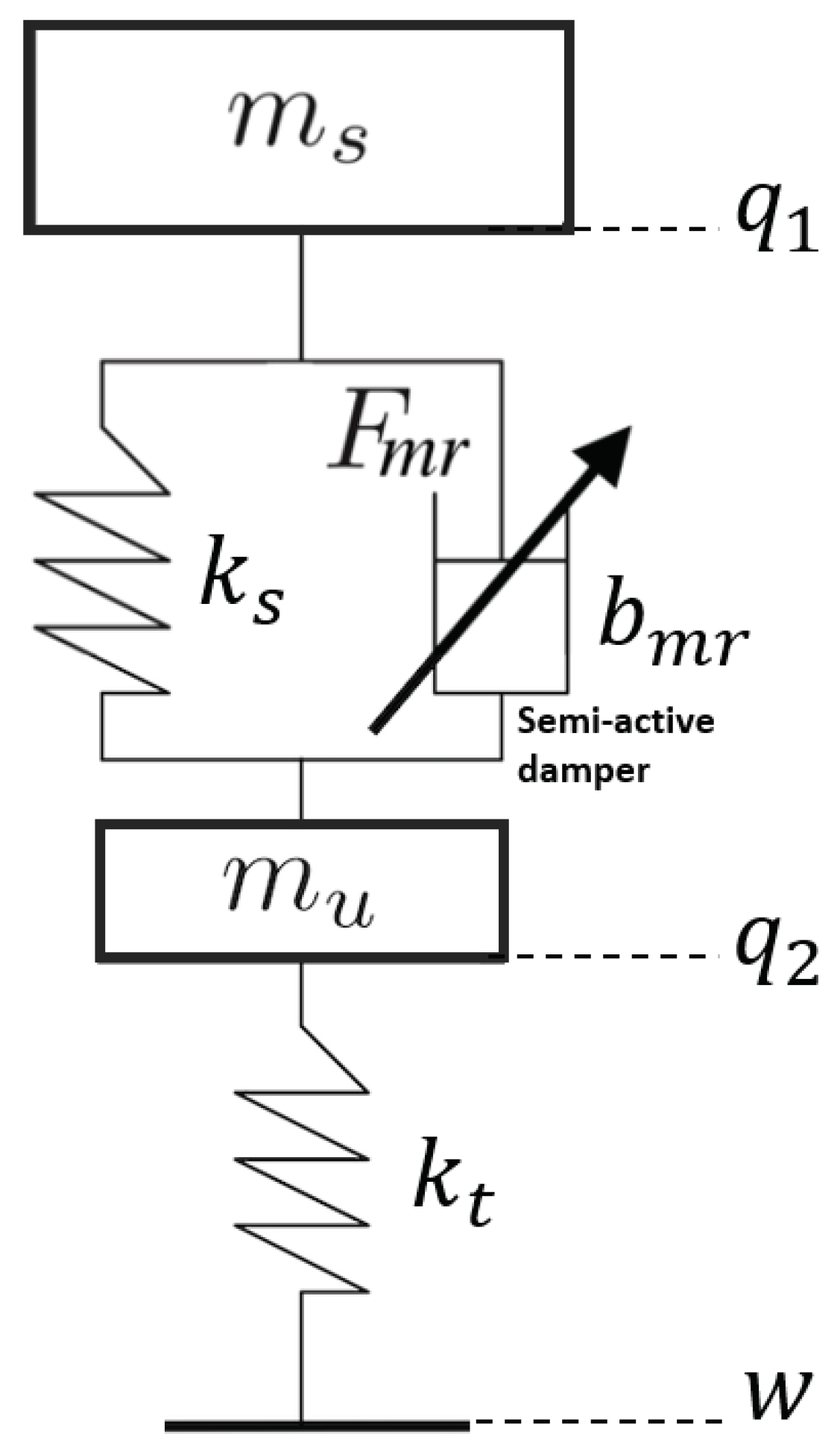
The two-degrees-of-freedom control-oriented quarter-car model is used due to its simplicity and controllability, where this model is depicted in Figure 1. The two degrees of freedom are sprung mass () and unsprung mass () displacements, respectively, and . The tire and suspension systems are denoted by a damper that connects the two masses and spring with stiffness coefficient . is the MR damper force with the that is the damping rate of the shock absorber. Here, w is the road profile, and it is assumed that the wheel–road contract is ensured.
It is necessary to write the dynamic model of a quarter-car semi-active suspension system as follows:
Here, is spring force, is damper deflection assumed to be measured, and is deflection velocity that can be computed from .
The behavior of the semi-active MR damper is represented using the Shuqi Guo model [16] with.
where , , and are constant parameters, while varies according to the current in coil with following: . This model allows to fulfill the dissipativity constraints of the semi-active damper. This parameter is defined as the control input to ensure the controllability of the damper, while stiffness () and damping () parameters are defined by (3). Table 1 shows the nominal parameters of the MR damper [11,18] and the quarter-car model for the front and rear suspensions.
3. Formulation of the LPV Model
Next, the LPV model must be formulated. It is necessary to write the nonlinear model (1) and (2) in the LPV framework as (4).
The state-space representation of the quarter-car model is written as follows:
Here, w is the road disturbance and suspension deflection is measured output. The state vector x is selected as , in which the components are shown in (6).
The main approach to finding matrices is arranging the (1) according to state vector components, performance vector components and the measured signal. Then, results are arranged according to (5). These coefficients () give us the matrices for the control design. These matrices are found below:
In order to satisfy the dissipativity constraint, the control signal must be positive, as follow: . The solution of the positivity problem is defining the , where is the mean of [17]. The state-space representation is modified with the mentioned modification:
The new matrices are found below:
=, =
The parameter is dependent, while the filter F must be added into the (7) in order to make the controlled input matrix independent from the scheduling parameter [19]:
The new LPV system is presented with two scheduling variables (, ) by denoting [17], where :
A =
B=, =, C=
The input saturation has been considered with a solution from [19]. Here, system (9) is augmented by adding a saturation to the actuator with the below consideration:
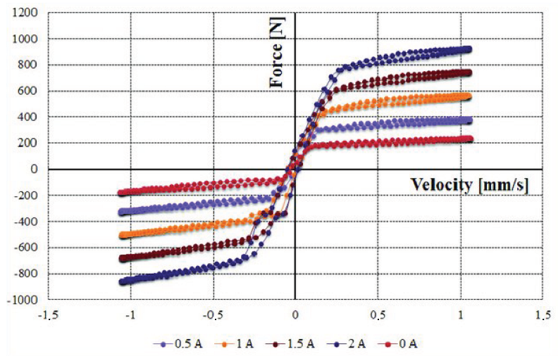
Figure 2 shows the MR damper force–deflection velocity () characteristics from MR damper.
4. LPV Control Synthesis
The LPV method has been used in order to design an online reconfigurable controller with external scheduling. The dynamical LPV system can be described in the form of (11).
where is a set of the varying parameters that describes a set of system. , , , , , , , , and are affine in .
The LPV performance problem is defined as choosing the parameter-varying controller, where the quadratic stability for a closed-loop system is ensured. The induced norm from the disturbance to the performances z is smaller than the value , as described in [21]. Hence, the minimization task is given as:
The solution of an LPV problem is driven by the set of infinite-dimension LMIs that must be met for every , making it a convex problem. In practice, this problem is built up in reality by gridding the parameter space and calculating the set of LMIs that hold on the subset of , as shown in [22]. The feasibility of a collection of LMIs that can be solved numerically may be represented as the presence of a controller that solves the quadratic LPV -performance issue. If there exists a matching the following linear matrix inequality for all , the closed-loop LPV system is exponentially stable with its gained less than , where is a parameter-dependent Lyapunov function for the closed-loop system for all if a solution can be found. The presence of the solution is demonstrated in [23].
The state-space formulation (9), which was presented in the previous section, is used in this control synthesis. Next, it is necessary to define the performance specifications in order to achieve the desired trade-off between ride comfort, stability, and road holding. The trade-off between these performance specifications makes the system adaptive.
The vehicle’s sprung mass acceleration frequency response must be kept small in the frequency range [0.5–10] Hz [24]. Thus, vehicle body acceleration must be minimized for the sake of increasing passenger comfort with the following optimization criterion:
The frequency response of suspension deflection must be small, at [0–20] Hz, in order to keep it far from the structural limits. Thus, suspension deflection must be minimized to guarantee the stability of the vehicle:
The frequency response of the tire deformation must be small at [0–20] Hz to decrease variations of side force in order to guarantee stability. For this reason, it is necessary to minimize the dynamic tire load with the optimization criterion:
These performances are inserted in a performance vector:
The relative displacement between sprung and unsprung masses is the measured signal, and the vertical force generated by the MR damper is the control input u with the dynamics listed in (2).
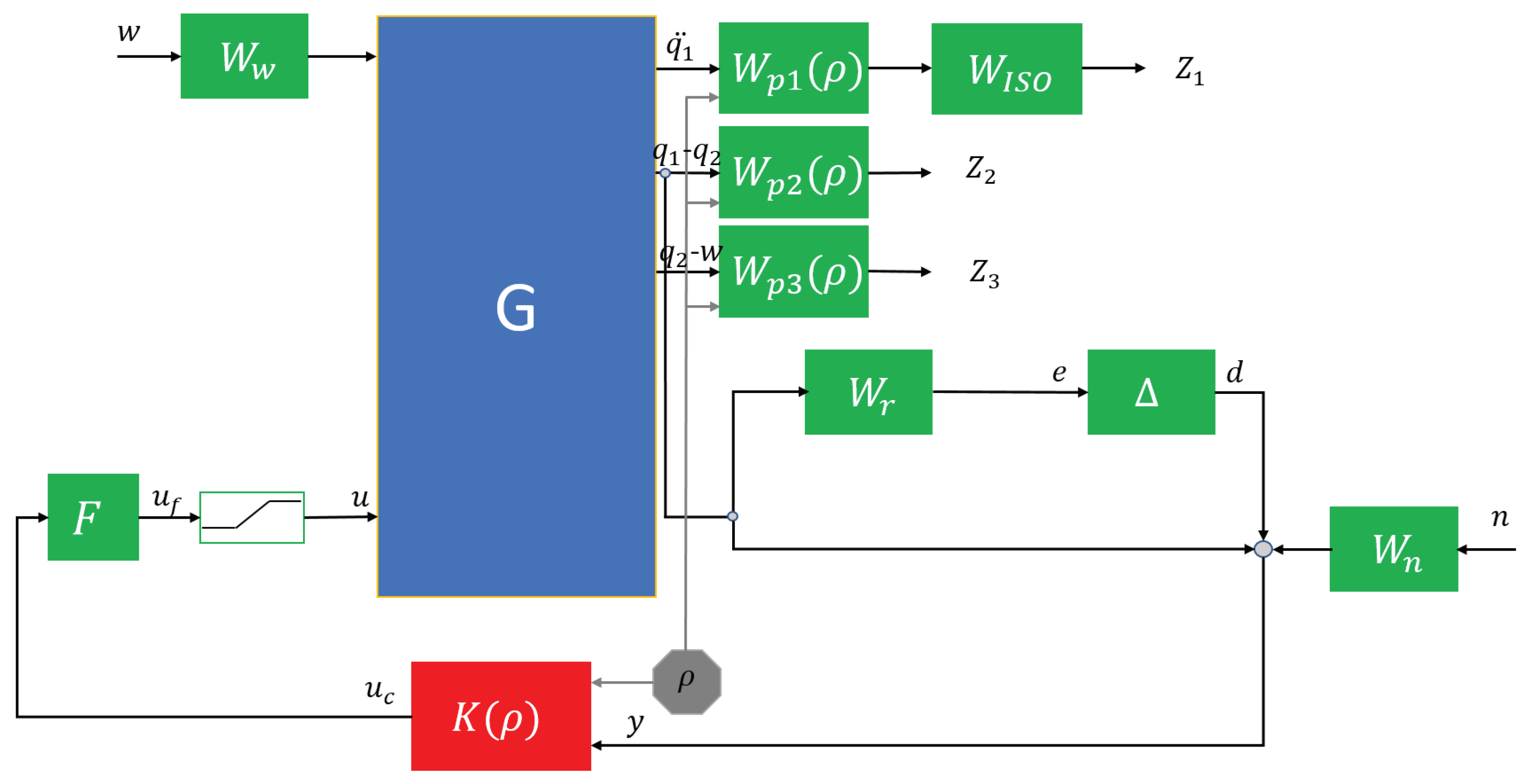
A closed-loop architecture of the introduced LPV-based controller that is founded on a weighting strategy is shown in Figure 3.
Here, K is the designed LPV controller characterized with the scheduling variable responsible for online control reconfiguration for the quarter-car control-oriented model G, is the control signal from the controller, F is the filter mentioned in the previous section with calculated and u is the control input after saturation, while performance outputs are represented as z.
The unmodeled dynamic are considered with below conditions:
- at high frequencies;
- at low frequencies;
- stable with the norm condition .
The uncertainties of the model are also considered and denoted with the weighting function and . The weighting function of sensor noises n is , while the road disturbance’s w weighting function is .
Performance weighting functions are responsible for keeping performances, which are the vertical body acceleration (), suspension deflection (), and tire deformation (), small over the required frequency range. represents driving comfort, denotes directional stability, and presents dynamic tire load and road holding. The weighting functions need to be considered as penalty functions; therewith, weights should be large where small signals are desired and vice versa.
Since the specified performance designations may conflict, performance weighting functions must be developed in such a way that a relevant trade-off between them can be assured. In addition, a scheduling variable is included to shape weighting functions , , and to ensure control reconfiguration in case one of the specified performances becomes more relevant owing to predicted future road conditions. As a result, the following performance weighting factors for passenger comfort and road holding are chosen in a second-order proportional form, as follows:
where and are designed parameters. The weighting functions , , and do not contain the scheduling variable , and they are presented in similar proportional and linear forms.
If the driving comfort is preferred, the scheduling variable is chosen as , while if this preference is for the road holding and stability of the vehicle, then the scheduling variable is in the designed controller. The combination of these performances can be defined by the being between these edge values.
It is necessary to apply a filter on the sprung mass acceleration to characterize human comfort [25]. This filter is applied to the first performance, which is vertical acceleration. The location of this filter is shown in Figure 3. The transfer function of the filter is depicted in (14).
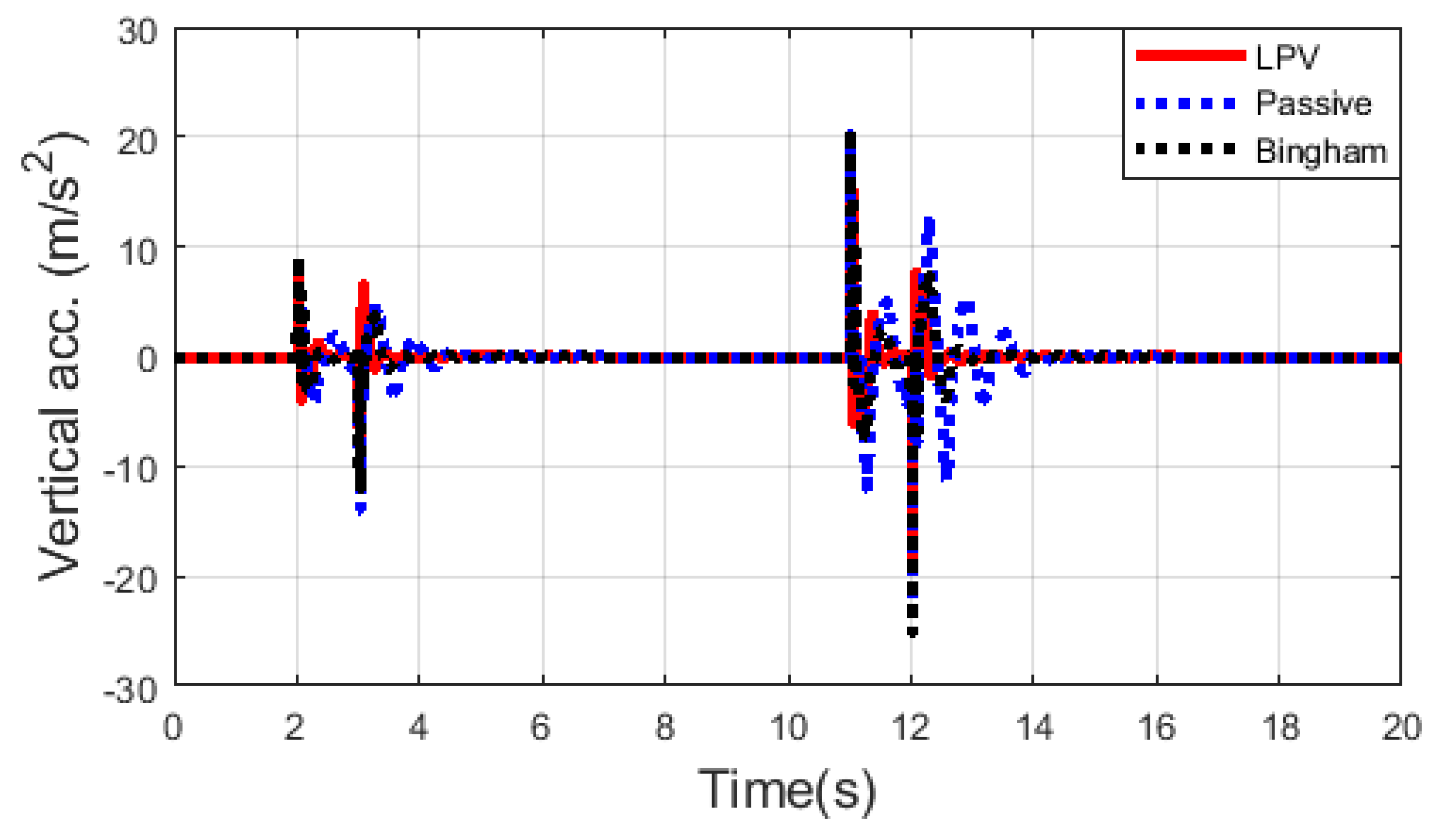
First, the designed controller is validated and compared in Simulink with the passive quarter-car model and Bingham suspension model. The Bingham model was selected because the behavior of an MR damper is easily described with that model [26,27]. The road irregularity for simulation contains 50 mm bump in the 2nd second and a 100 mm bump in 11 s. The scheduling parameter is chosen as follows in order to show the balance trade-off between driving comfort and road holding and stability.
It is clearly shown that the amount of vertical acceleration is reduced so that driving comfort is improved with the proposed reconfigurable LPV controller. The improvements of the proposed controller are 33.65% and 15.4% against the passive suspension and the Bingham model, respectively. The improvements are shown in Table 2. Please note that there is a point where this controlled acceleration value is greater than the passive one in the 3rd second. Figure 4 shows the vertical acceleration result of the simulation.
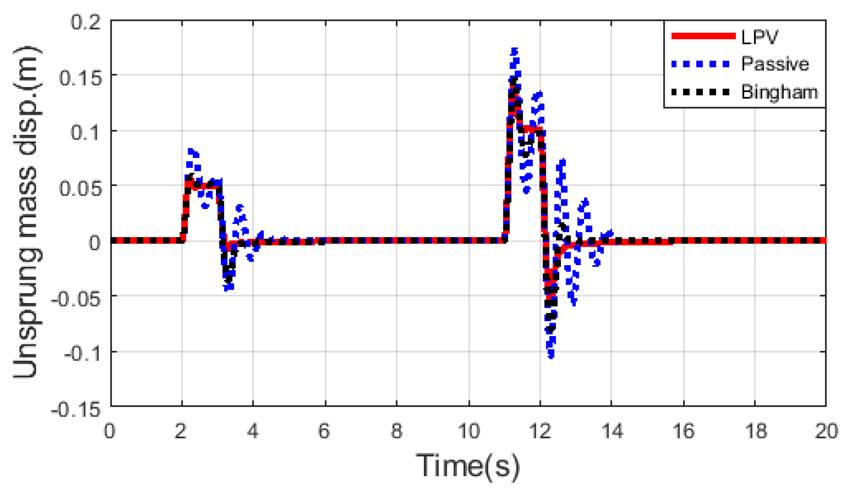
Displacement of unsprung mass is not in the performance matrix, while it also shows the stability performance. Thus, it is also necessary to show the result of unsprung mass displacement, see Figure 5. It is well depicted that displacement of unsprung mass is smaller with the proposed controller compared to passive suspension and the Bingham model. RMS values of unsprung mass displacement for passive suspension and Bingham model are 0.0642 and 0.0527, while this value is 0.0514 with an introduced controller with 19.94% and 2.47% improvements, respectively.
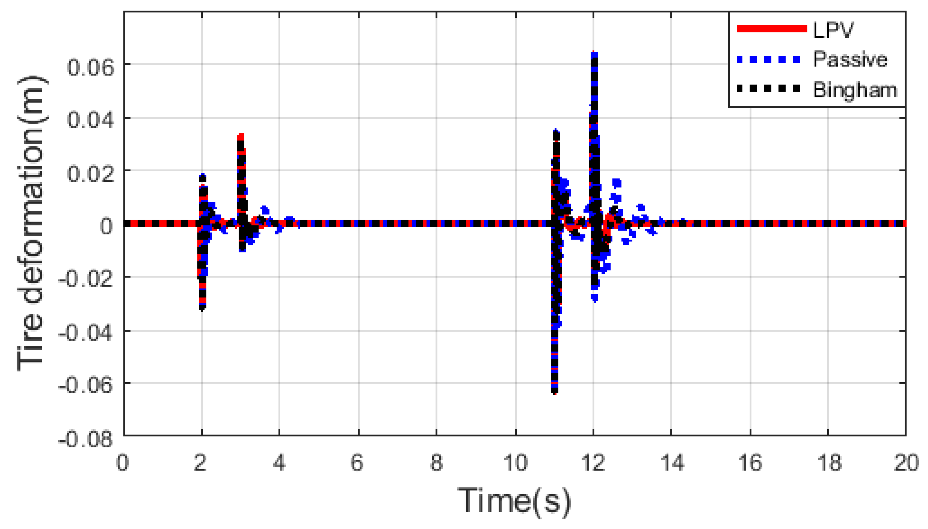
The tire deformation is also reduced by 21.6% and 6.67% with the new controller against the passive and Bingham model. The result of tire deformation is shown in Figure 6.
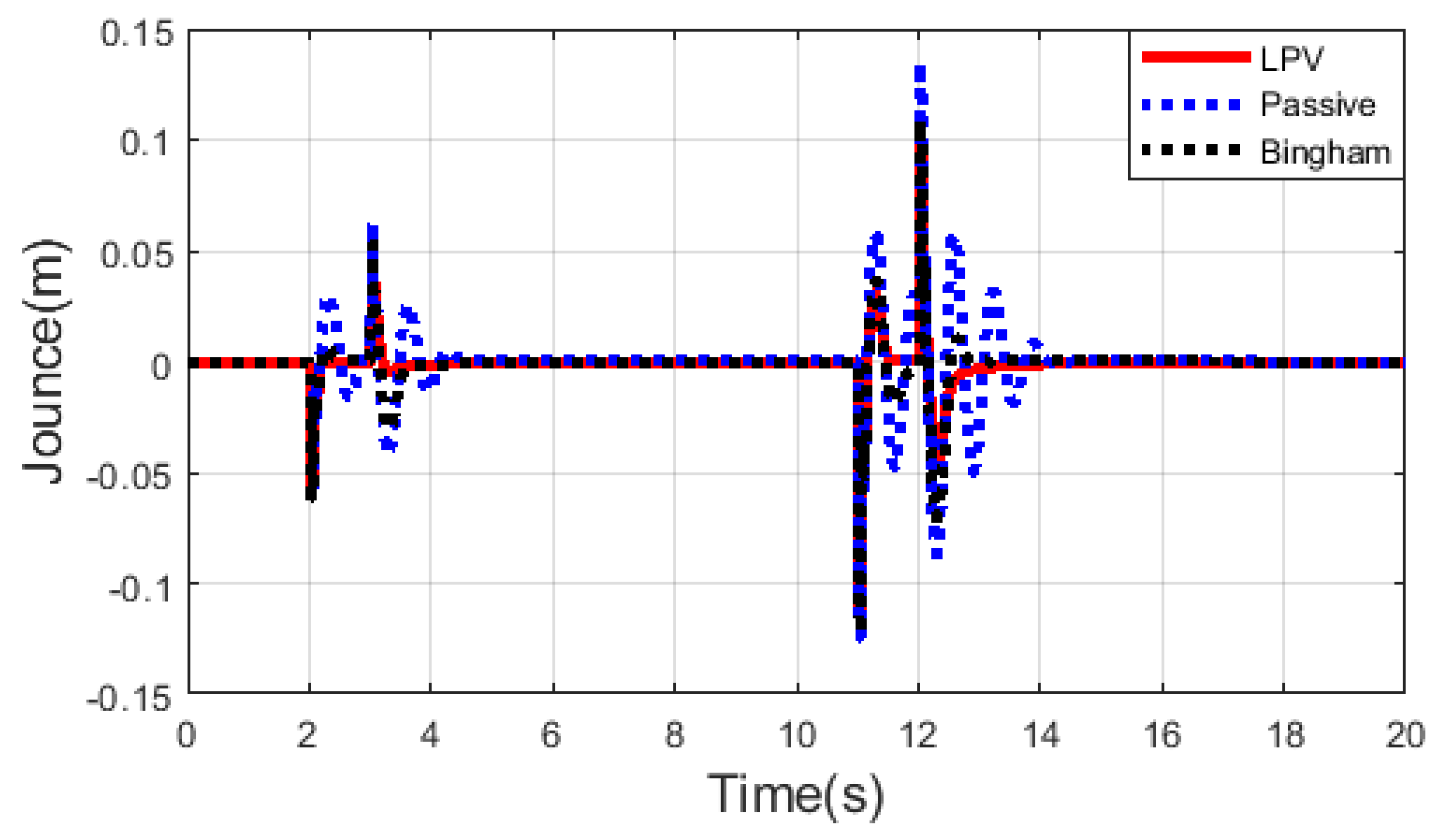
The proposed LPV controller also improved the suspension deflection performance by 33.07% and 10.76% against the passive and Bingham models, respectively. This improvement is well depicted in Figure 7.
5. Simulation Results
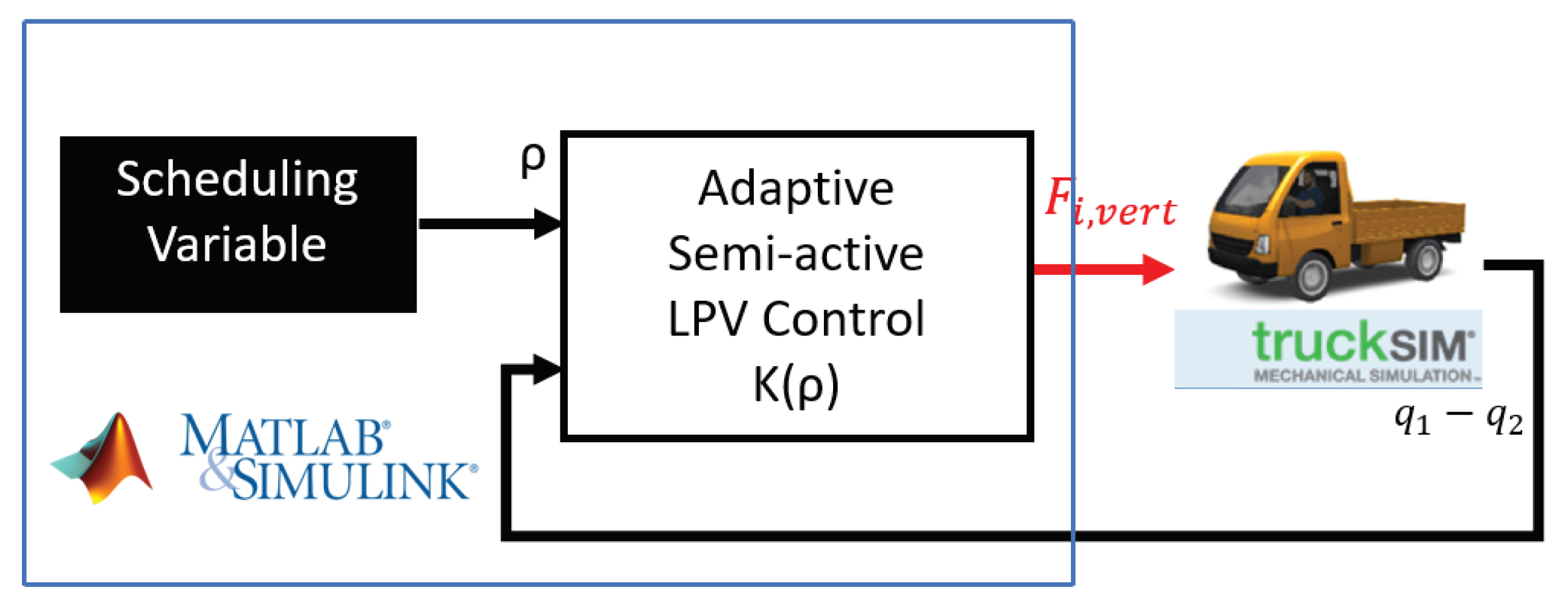
Demonstration of the proposed adaptive semi-active suspension controller was simulated in the TruckSim environment. Figure 8 shows the architecture of a simulation. A compact utility truck is selected for the simulation with independent rear and the front suspension and half a tonne of payload. Parameters of the simulated truck are shown in Table 3. The road distortion is based on real geographical data and integrated into the TruckSim environment. The simulations are to show the performance results in two corners of the scheduling variable (). Modification of scheduling variable configures the controller, whereby if the scheduling variable is close to zero, the controller works as safety/stability-oriented, while if it is close to one, the controller is in comfort-oriented mode. LPV design allows the online change of the scheduling variable. This real-time scheduling variable modification makes the semi-active suspension controller adaptive. This scheduling variable can be designed for different velocities, road irregularities, and road categories. The system architecture is shown in Figure 8, where measured output is forwarded to the controller, vertical force generated by the MR damper is the control input, and the scheduling variable reconfigures the controller’s behavior. TruckSim environment is integrated into the MATLAB/Simulink environment where the controller is performed here.
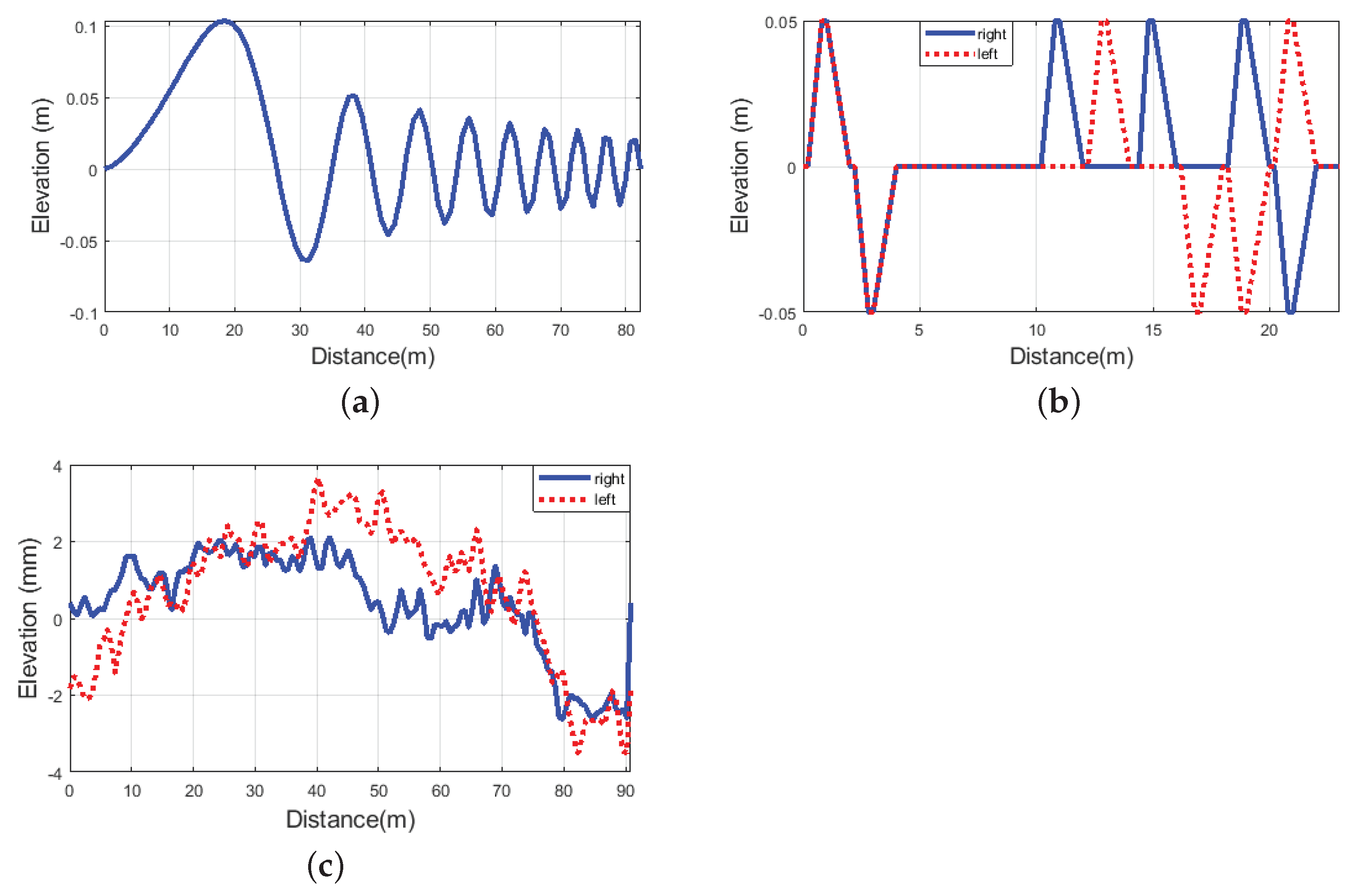
Adaptivity of the introduced controller is demonstrated with three different road irregularities, which are random road roughness, sine-sweep road irregularity, and several 5 cm bumps. The sine-sweep road irregularity represents a typical road at the bus stop due to its rolled-up structures with longitudinal sinusoidal road distortion with growing frequency, see Figure 9a. The length of this irregularity is 83 m. The several bumps irregularities consist of different bumps following each other, with 5 cm height, to represent the poor road quality with discontinuities in the asphalt, while its length is 22 m, see Figure 9b. The road roughness represents the general road roughness in the asphalt, and this irregularity is shown in Figure 9c. Roughness of 92 m is applied to the simulation.
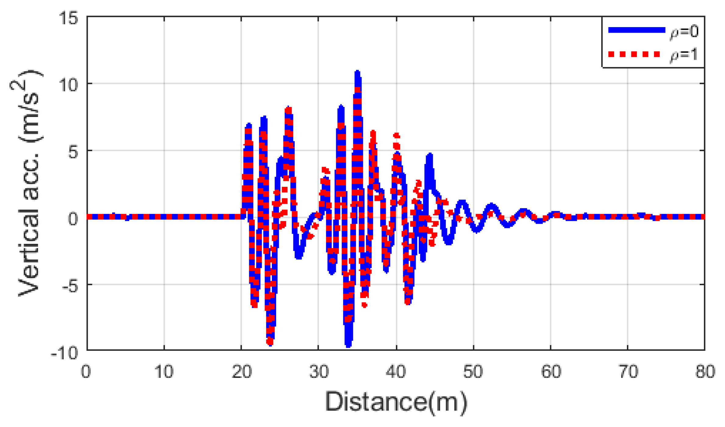
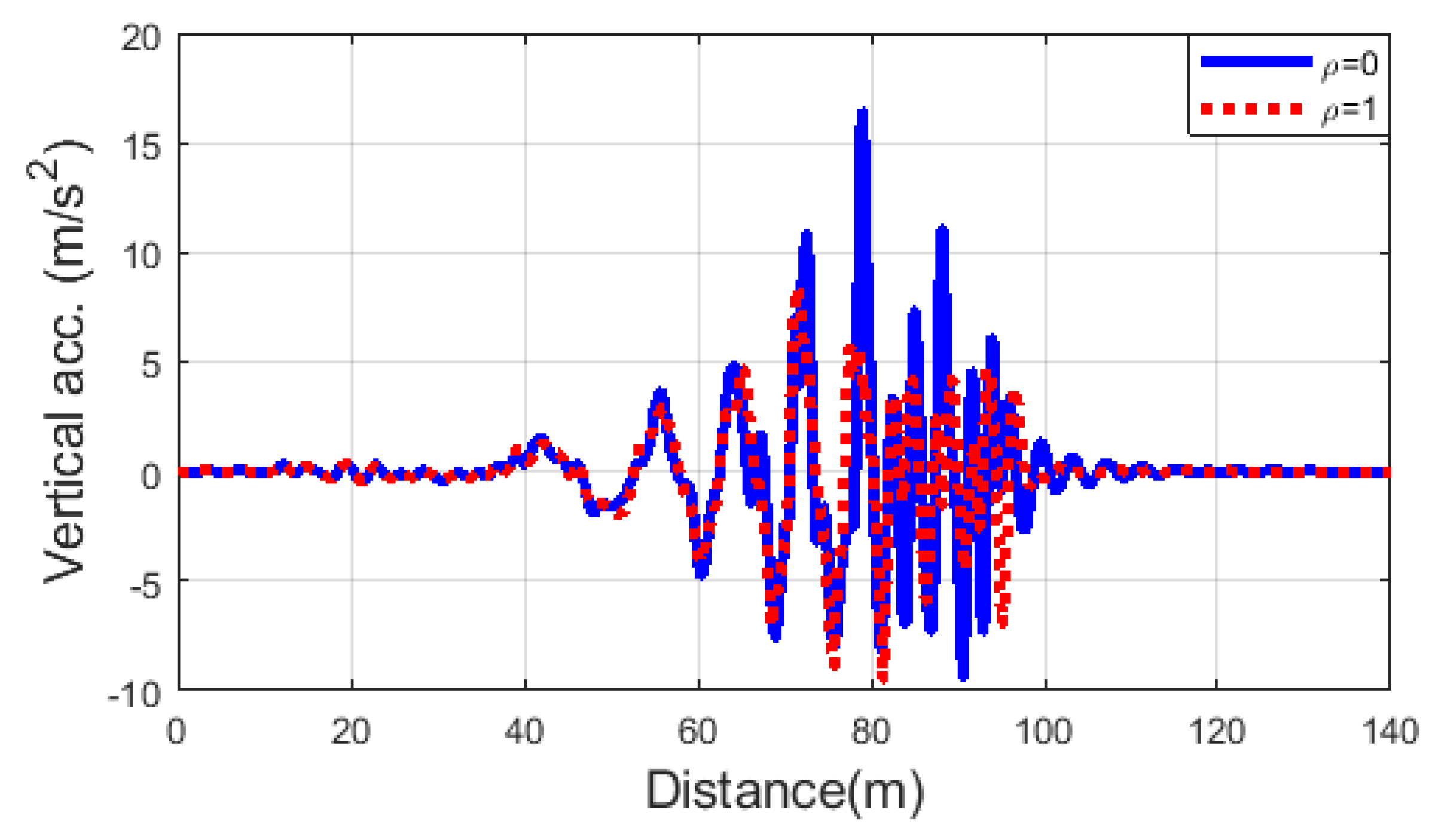
The operation of the proposed adaptive semi-active suspension controller in case of several bumps on the road is depicted in Figure 10, Figure 11 and Figure 12. It is well demonstrated that with the comfort-oriented setting of , vertical acceleration is decreased compared to the stability-oriented controller setting of , as shown in Figure 10. Thus, through the smaller values of sprung mass vertical acceleration, passenger comfort can be enhanced with the adaptive controller.
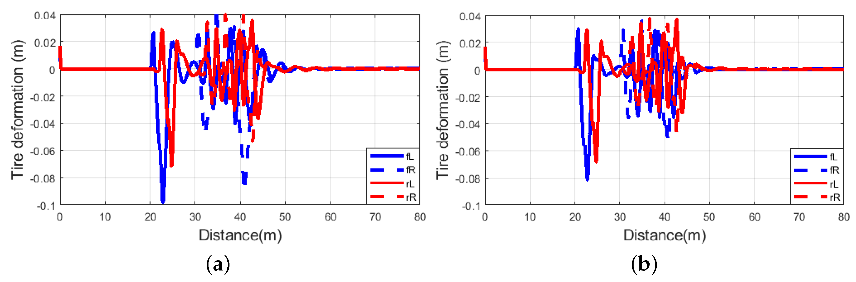
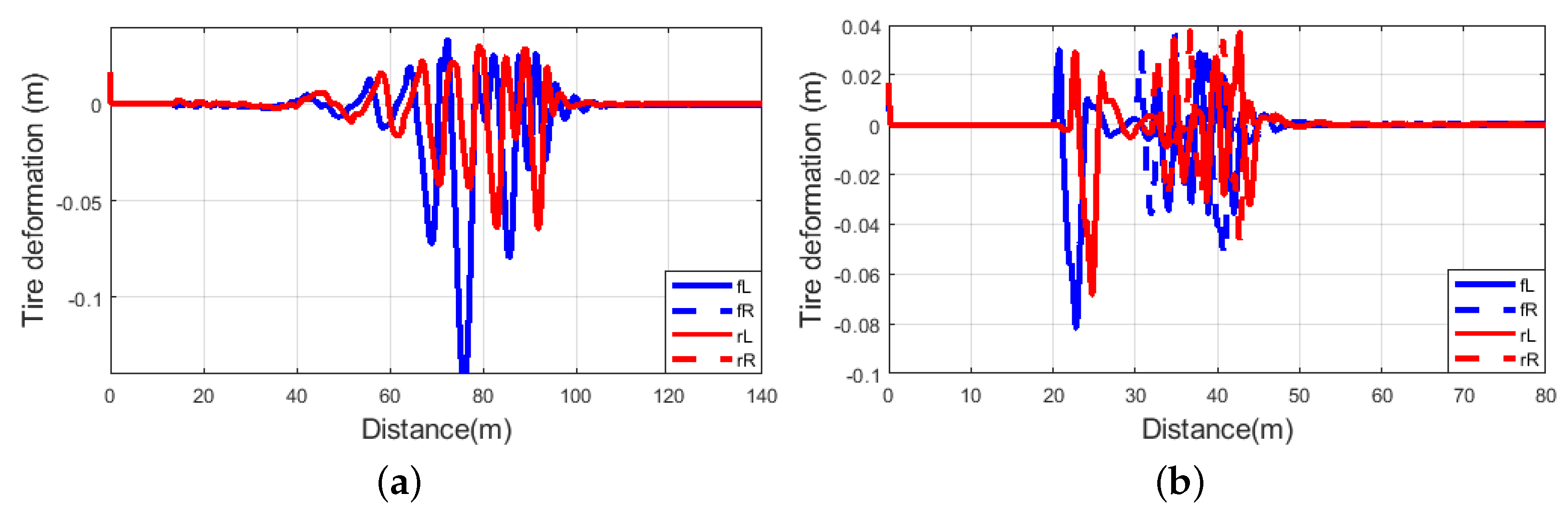
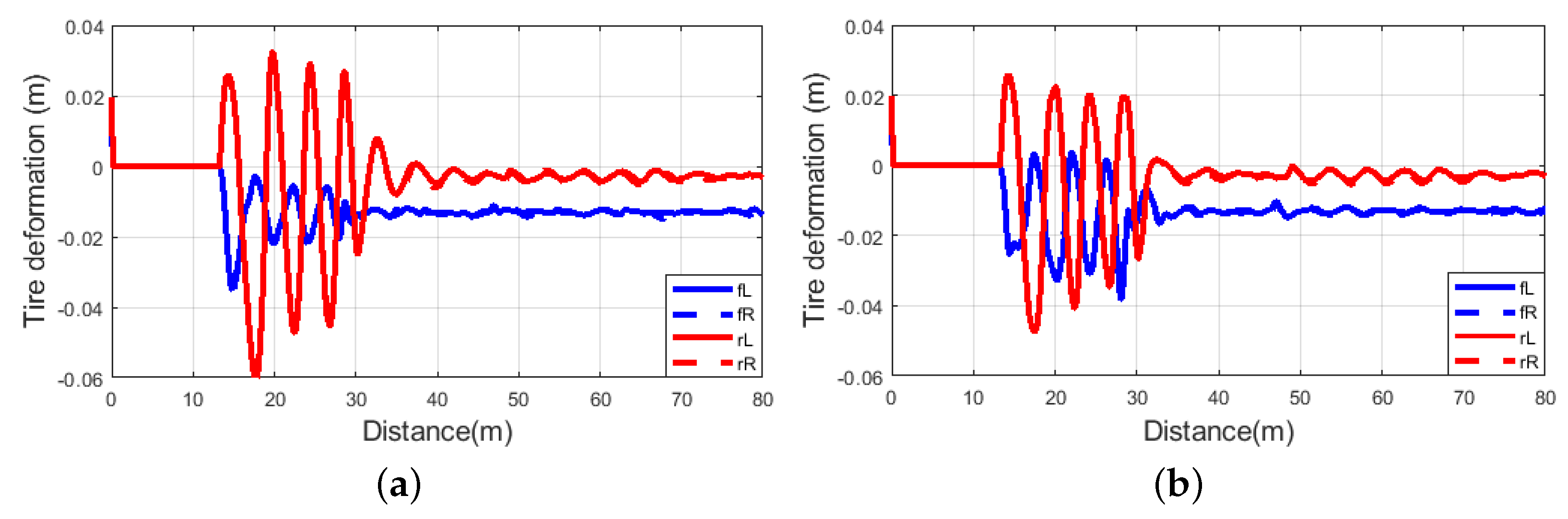
On the other hand, by increasing the value of the LPV controller scheduling variable , stability-related performances decreases. For instance, tire deformation of the comfort-oriented suspension setting shown in Figure 11a is slightly bigger than that of the stability-oriented setting depicted in Figure 11b.
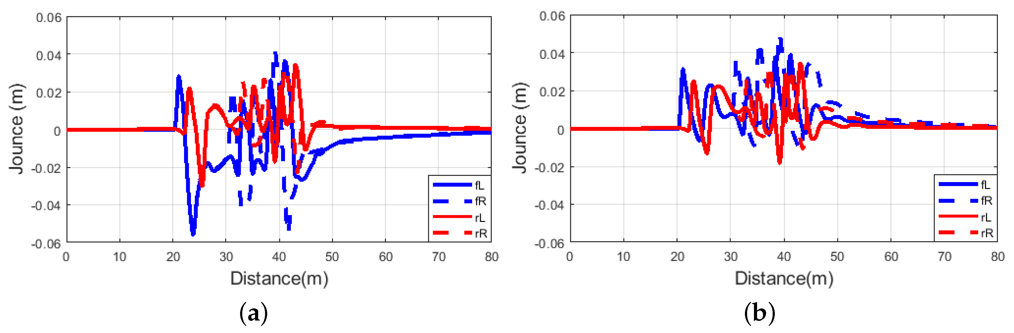
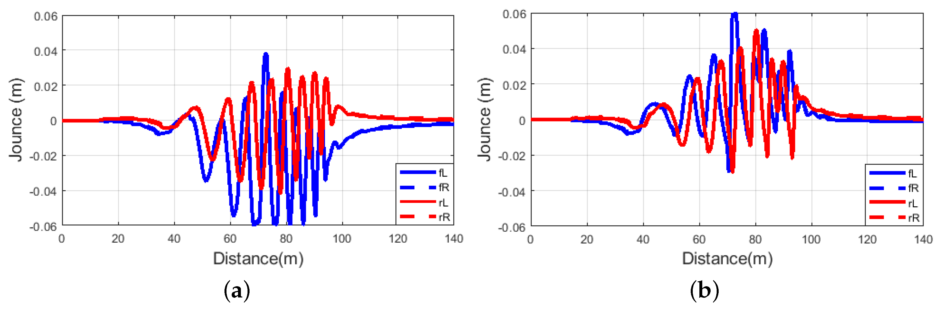
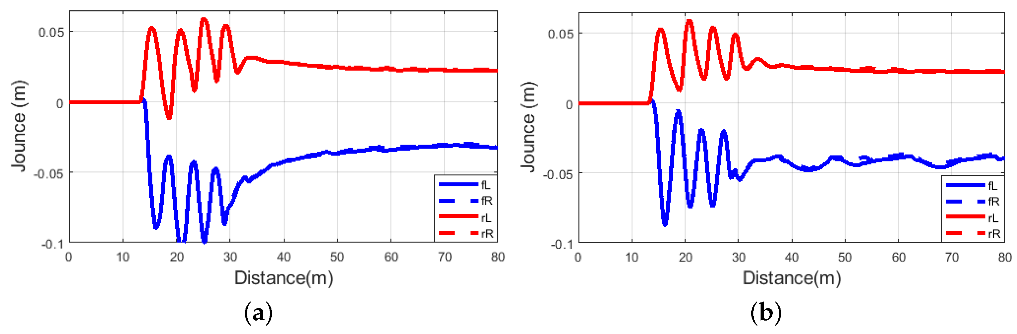
Moreover, suspension deflection of the comfort-oriented setting illustrated in Figure 12a is significantly bigger than that with applying the stability-oriented setting depicted in Figure 12b.
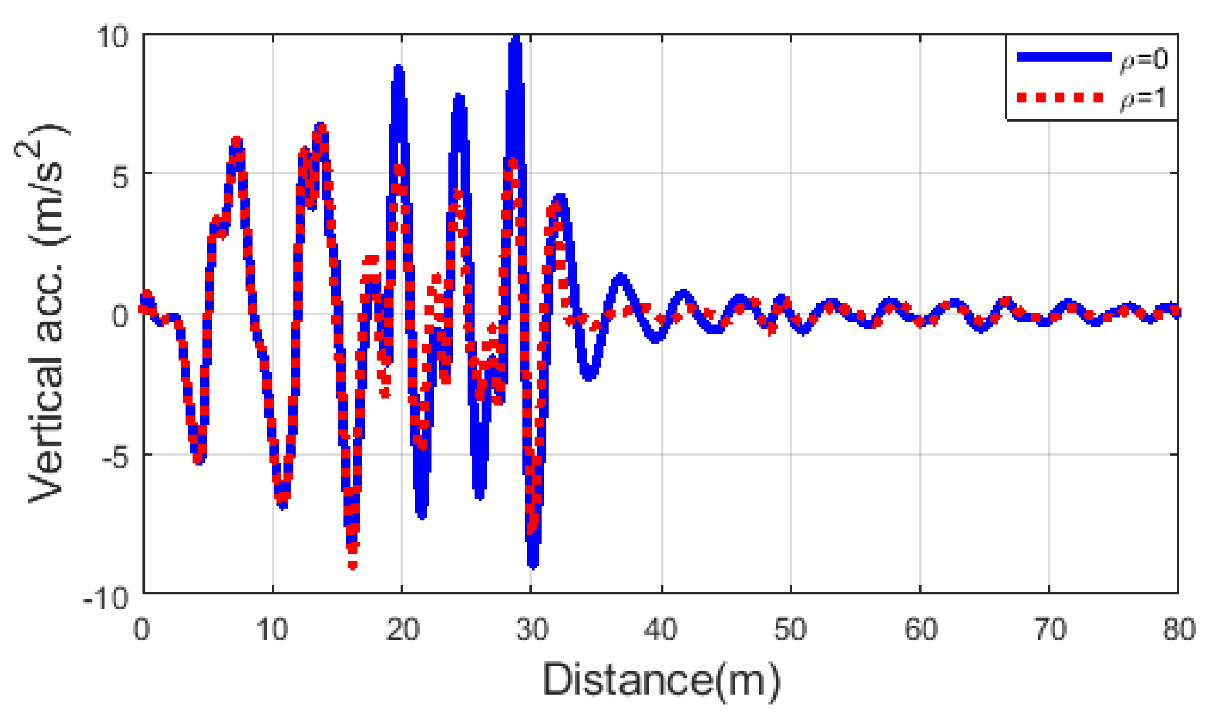
The differences in performance are even more pronounced on the road with the sine-sweep irregularity, as illustrated with the vertical acceleration signals of the sprung mass in Figure 13, showing significant improvement for the comfort-oriented setting.
As expected due to design of the adaptive LPV controller, tire deformation and suspension deflection for the comfort-oriented setting shown in Figure 14a and Figure 15a are bigger than those with the stability-oriented setting depicted in Figure 14b and Figure 15b.
Finally, a simulation was performed on the road roughness. As Figure 16 demonstrates, with the comfort-oriented setting of , vertical acceleration of the simulated vehicle has been decreased greatly, corresponding to the better riding comfort of the vehicle.
Similarly to the previous scenarios, with the comfort-oriented setting on the road roughness irregularity, tire deformation and suspension deflection depicted in Figure 17a and Figure 18a are slightly bigger than those with the stability-oriented setting shown in Figure 17b and Figure 18b.
The vehicle stability, road holding, and driving comfort can be ensured by controlling the vertical dynamics of the vehicle. Thus, the goal is to control the force of the dampers for each corner of the vehicle. This proposed and validated controller calculates the dedicated damper force. The scheduling variable changes the characteristics of the controller; thus, calculated damper forces for each corner vary according to the defined scheduling variable. This scheduling variable is designed depending on the road irregularities, vehicle velocity, and other road conditions. This scheduling variable design methods have already been introduced in our previous papers [11,12,13,14,15].
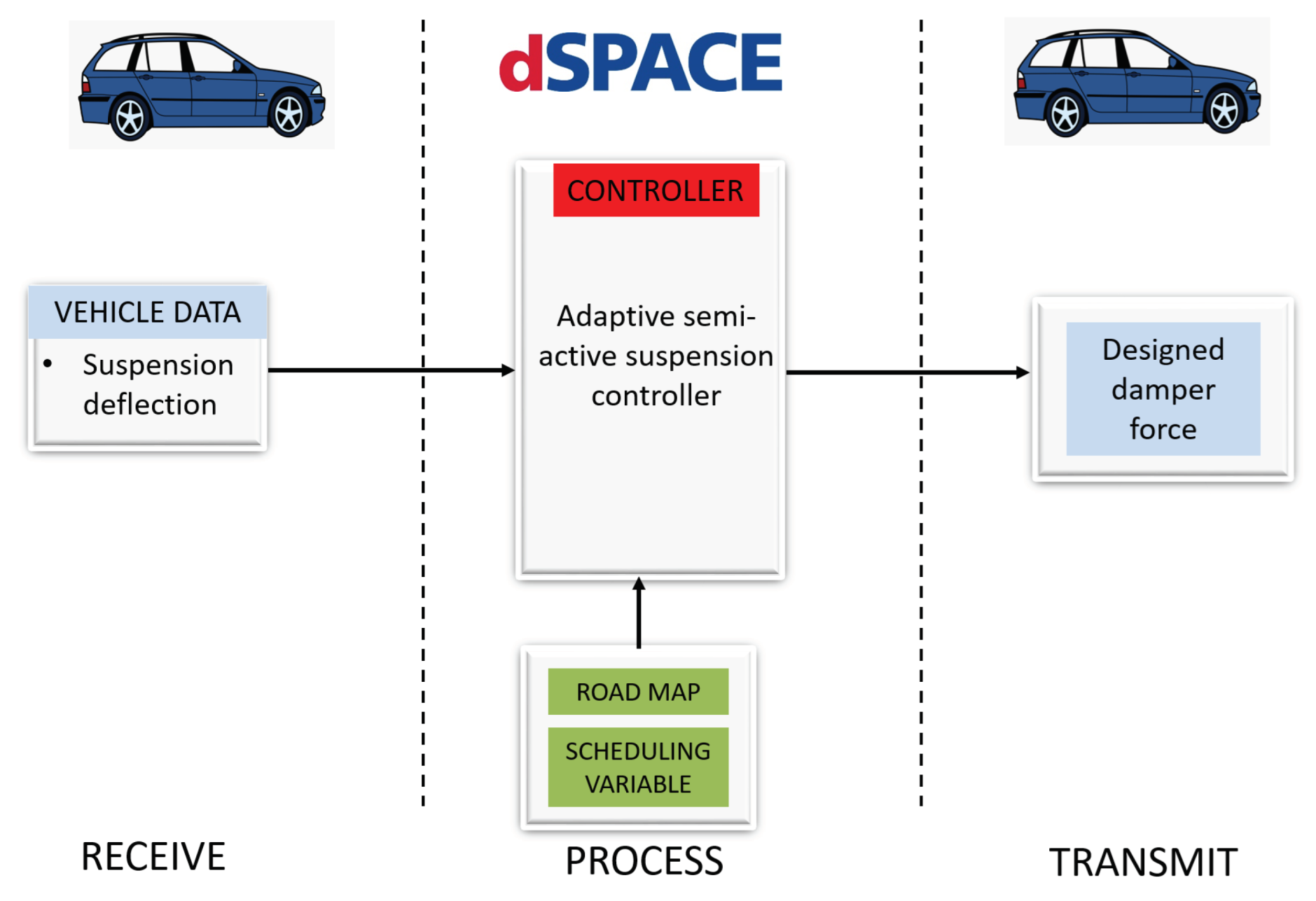
The proposed controller is feasible for the real-time application. The MATLAB/Simulink model of the adaptive semi-active suspension control can be implemented in dSPACE MicroAutoBox II, while this possible model is shown in Figure 19.
There are three parts which are receiving, processing, and transmitting. The receiving part acquires the data from CAN, and it will be transformed into operable signals. Then, the operable signals will be gathered in the receiving part, and the controller calculates the damper force with provided scheduling variable and road data. The calculated damper force will be forwarded through CAN and serial interface.
Performance of the vehicle can be measured with multiple sensors and methods. In order to measure suspension deflection, a suspension displacement sensor may be used. A chassis acceleration sensor can be used to measure the vertical acceleration of the vehicle. Measurement of the tire deformation is not as easy as other performance, while there are methods for finding tire deformation of the vehicle [28,29,30]. The earlier study [31] identified that the computational time costs of the control laws can be reduced by considering the LPV model. The scheduling variable of our proposed method varies, and it may cause a high computational time. This time can be reduced with further study.
6. Conclusions
This paper proposed an online reconfigurable road-adaptive semi-active suspension controller that achieves the performance objectives and satisfies the dissipativity constraint. The model is based on a nonlinear static model of the semi-active MR damper. Adaptivity of the proposed controller has been managed by using an external scheduling variable that allows the trade-off between performances, while the control design is based on the LPV framework. In order to demonstrate the proposed controller, the controlled model is compared with the passive suspension and Bingham model in Simulink, while the adaptivity of the controller has been validated with TruckSim simulation with different scheduling variables.The simulations prove that the proposed adaptive controller has better performance results than the passive semi-active suspension and the controlled Bingham model. Future work will focus on the different scheduling variable designs in consideration of road irregularity and vehicle velocity.
Author Contributions
Conceptualization, H.B. and A.M.; methodology, H.B.; software, H.B.; validation, H.B.; formal analysis, P.G.; investigation, P.G.; resources, H.B. and A.M.; data curation, H.B.; writing—original draft preparation, H.B.; writing—review and editing, H.B., A.M. and P.G.; visualization, H.B.; supervision, P.G. and O.S.; project administration, P.G. and O.S.; funding acquisition, P.G. All authors have read and agreed to the published version of the manuscript.
Funding
The research presented in this paper, carried out by Institute for Computer Science and Control, was supported by the Ministry for Innovation and Technology and the National Research, Development and Innovation Office within the framework of the National Lab for Autonomous Systems. The research was partially supported by the Hungarian Government and co-financed by the European Social Fund through the project “Talent management in autonomous vehicle control technologies” (EFOP-3.6.3-VEKOP- 16-2017-00001).
Conflicts of Interest
The authors declare no conflict of interest.
References
- de Jesus Lozoya-Santos, J.; Tudón-Martínez, J.C.; Morales-Menendez, R.; Ramirez-Mendoza, R.; Garza-Castanón, L.E. A fault detection method for an automotive magneto-rheological damper. IFAC Proc. Vol. 2012, 45, 1209–1214. [Google Scholar] [CrossRef]
- Sename, O. Review on LPV Approaches for Suspension Systems. Electronics 2021, 10, 2120. [Google Scholar] [CrossRef]
- Theunissen, J.; Tota, A.; Gruber, P.; Dhaens, M.; Sorniotti, A. Preview-based techniques for vehicle suspension control: A state-of-the-art review. Annu. Rev. Control 2021, 51, 206–235. [Google Scholar] [CrossRef]
- Karnopp, D.; Crosby, M.J.; Harwood, R. Vibration control using semi-active force generators. J. Eng. Ind. 1974, 96, 619–626. [Google Scholar] [CrossRef]
- BalaMurugan, L.; Jancirani, J. An investigation on semi-active suspension damper and control strategies for vehicle ride comfort and road holding. Proc. Inst. Mech. Eng. Part I J. Syst. Control Eng. 2012, 226, 1119–1129. [Google Scholar] [CrossRef]
- Moaaz, A.O.; Ghazaly, N.M. Semi-active suspension system control using Skyhook and Groundhook controller. Int. J. Adv. Sci. Technol. 2019, 28, 424–433. [Google Scholar]
- Anaya-Martinez, M.; Lozoya-Santos, J.d.J.; Félix-Herrán, L.; Tudon-Martinez, J.C.; Ramirez-Mendoza, R.A.; Morales-Menendez, R. Control of Automotive Semi-Active MR Suspensions for In-Wheel Electric Vehicles. Appl. Sci. 2020, 10, 4522. [Google Scholar] [CrossRef]
- Piñón, A.; Favela-Contreras, A.; Félix-Herrán, L.C.; Beltran-Carbajal, F.; Lozoya, C. An ARX Model-Based Predictive Control of a Semi-Active Vehicle Suspension to Improve Passenger Comfort and Road-Holding. Actuators 2021, 10, 47. [Google Scholar] [CrossRef]
- Sharma, R.C.; Palli, S.; Sharma, N.; Sharma, S.K. Ride Behaviour of a Four-wheel Vehicle using H Infinity Semi-active Suspension Control under Deterministic and Random Inputs. Int. J. Veh. Struct. Syst. 2021, 13, 234–237. [Google Scholar] [CrossRef]
- Ye, H.; Zheng, L. Comparative study of semi-active suspension based on LQR control and H 2/Hinf multi-objective control. In Proceedings of the 2019 Chinese Automation Congress (CAC), Hangzhou, China, 22–24 November 2019; IEEE: Piscataway, NJ, USA, 2019; pp. 3901–3906. [Google Scholar]
- Basargan, H.; Mihály, A.; Gáspár, P.; Sename, O. Adaptive Semi-Active Suspension and Cruise Control through LPV Technique. Appl. Sci. 2021, 11, 290. [Google Scholar] [CrossRef]
- Basargan, H.; Mihály, A.; Gáspár, P.; Sename, O. Road adaptive semi-active suspension and cruise control through LPV technique. In Proceedings of the 2021 European Control Conference (ECC), Delft, The Netherlands, 29 June–2 July 2021; IEEE: Piscataway, NJ, USA, 2021; pp. 461–466. [Google Scholar] [CrossRef]
- Basargan, H.; Mihály, A.; Gáspár, P.; Sename, O. Integrated multi-criteria velocity and semi-active suspension control based on look-ahead road information. In Proceedings of the 2020 28th Mediterranean Conference on Control and Automation (MED), Saint-Raphaël, France, 15–18 September 2020; IEEE: Piscataway, NJ, USA, 2020; pp. 25–30. [Google Scholar]
- Basargan, H.; Mihály, A.; Kisari, Á.; Gáspár, P.; Sename, O. Vehicle Semi-active Suspension Control with Cloud-based Road Information. Period. Polytech. Transp. Eng. 2021, 49, 242–249. [Google Scholar] [CrossRef]
- Basargan, H.; Mihály, A.; Gáspár, P.; Sename, O. Road Quality Information Based Adaptive Semi-active Suspension Control. Period. Polytech. Transp. Eng. 2021, 49, 210–217. [Google Scholar] [CrossRef]
- Guo, S.; Yang, S.; Pan, C. Dynamic modeling of magnetorheological damper behaviors. J. Intell. Mater. Syst. Struct. 2006, 17, 3–14. [Google Scholar] [CrossRef]
- Do, A.L.; Sename, O.; Dugard, L. An LPV control approach for semi-active suspension control with actuator constraints. In Proceedings of the 2010 American Control Conference, Baltimore, MD, USA, 30 June–2 July 2010; IEEE: Piscataway, NJ, USA, 2010; pp. 4653–4658. [Google Scholar]
- Nino-Juarez, E.; Morales-Menendez, R.; Ramirez-Mendoza, R.; Dugard, L. Minimizing the frequency in a black box model of a mr damper. In Proceedings of the 11th Mini Conference on Vehicle System Dynamics, Identification and Anomalies, Budapest, Hungary, 10–12 November 2008. [Google Scholar]
- Poussot-Vassal, C. Robust LPV Multivariable Automotive Global Chassis Control. Ph.D. Thesis, Institut National Polytechnique de Grenoble-INPG, Grenoble, France, 2008. [Google Scholar]
- Rossi, A.; Orsini, F.; Scorza, A.; Botta, F.; Belfiore, N.P.; Sciuto, S.A. A review on parametric dynamic models of magnetorheological dampers and their characterization methods. Actuators 2018, 7, 16. [Google Scholar] [CrossRef] [Green Version]
- Bokor, J.; Balas, G. Linear Parameter varying systems: A geometric theory and applications. IFAC Proc. Vol. 2005, 38, 12–22. [Google Scholar] [CrossRef] [Green Version]
- Wu, F.; Yang, X.H.; Packard, A.; Becker, G. Induced l2-norm control for LPV systems with bounded parameter variation rates. Int. J. Nonlinear Robust Control 1996, 6, 983–998. [Google Scholar] [CrossRef]
- Yu, J.; Sideris, A. Hinf control with parametric Lyapunov functions. Syst. Control Lett. 1997, 30, 57–69. [Google Scholar] [CrossRef]
- Poussot-Vassal, C.; Sename, O.; Dugard, L.; Gaspar, P.; Szabo, Z.; Bokor, J. A new semi-active suspension control strategy through LPV technique. Control Eng. Pract. 2008, 16, 1519–1534. [Google Scholar] [CrossRef]
- Zuo, L.; Nayfeh, S. Low order continuous-time filters for approximation of the ISO 2631-1 human vibration sensitivity weightings. J. Sound Vib. 2003, 265, 459–465. [Google Scholar] [CrossRef]
- Mihály, A.; Kisari, Á.; Gáspár, P.; Németh, B. Adaptive semi-active suspension design considering cloud-based road information. IFAC-PapersOnLine 2019, 52, 249–254. [Google Scholar] [CrossRef]
- Sapiński, B.; Filuś, J. Analysis of parametric models of MR linear damper. J. Theor. Appl. Mech. 2003, 41, 215–240. [Google Scholar]
- Zhang, C.; Zhao, W.; Wang, W.; Zhang, J. Vision-based tire deformation and vehicle-bridge contact force measurement. Measurement 2021, 183, 109792. [Google Scholar] [CrossRef]
- Delvecchio, D.; Spelta, C.; Savaresi, S.M. Estimation of the tire vertical deflection in a motorcycle suspension via Kalman-filtering techniques. In Proceedings of the 2011 IEEE International Conference on Control Applications (CCA), Denver, CO, USA, 28–30 September 2011; pp. 532–537. [Google Scholar] [CrossRef]
- Sergio, M.; Manaresi, N.; Tartagni, M.; Canegallo, R.; Guerrieri, R. On a road tire deformation measurement system using a capacitive–resistive sensor. Smart Mater. Struct. 2006, 15, 1700. [Google Scholar] [CrossRef]
- Morato, M.M.; Nguyen, M.Q.; Sename, O.; Dugard, L. Design of a fast real-time LPV model predictive control system for semi-active suspension control of a full vehicle. J. Frankl. Inst. 2019, 356, 1196–1224. [Google Scholar] [CrossRef]
Figure 1.
Quarter-car model.

Figure 2.
Force–deflection velocity characteristic of MR damper [20].
Figure 2.
Force–deflection velocity characteristic of MR damper [20].

Figure 3.
Closed-loop interconnection structure.

Figure 4.
Vertical acceleration.

Figure 5.
Unsprung mass displacement.

Figure 6.
Tire deformation.

Figure 7.
Suspension deflection.

Figure 8.
The architecture of a system.

Figure 9.
(a) Sine- sweep road. (b) Several bumps. (c) Road roughness.

Figure 10.
Vertical acceleration of several bumps.

Figure 11.
(a) Tire deformation of several bumps, . (b) Tire deformation of several bumps, .

Figure 12.
(a) Suspension deflection of several bumps, . (b) Suspension deflection of several bumps, .
Figure 12.
(a) Suspension deflection of several bumps, . (b) Suspension deflection of several bumps, .

Figure 13.
Vertical acceleration of sine sweep.

Figure 14.
(a) Tire deformation of sine sweep, . (b) Tire deformation of sine sweep, .

Figure 15.
(a) Suspension deflection of sine sweep, . (b) Suspension deflection of sine sweep, .

Figure 16.
Vertical acceleration of road roughness.

Figure 17.
(a) Tire deformation of road roughness, . (b) Tire deformation of road roughness, .

Figure 18.
(a) Suspension deflection of road roughness, . (b) Suspension deflection of road roughness, .
Figure 18.
(a) Suspension deflection of road roughness, . (b) Suspension deflection of road roughness, .

Figure 19.
Real-time model.


Table 1.
Parameters of MR damper and quarter-car.
| Parameters | Front | Rear | Unit |
|---|---|---|---|
| (Symbols) | Suspension | Suspension | |
| Sprung mass () | 214 | 336 | kg |
| Unsprung mass () | 40 | 40 | kg |
| Suspension Stiffness () | 30 | 60 | kN/m |
| Tire stiffness () | 220 | 220 | kN/m |
| Damping () | 50 | 50 | N/m/s |
| 1500 | 1500 | Ns/m | |
| 129 | 129 | s/m | |
| 0.788 × | 0.788 × | m/s | |
| 1.195 × | 1.195 × | m | |
| 400 | 400 | N |
Table 2.
Performance improvement.
| Performance | Passive RMS | Bingham RMS | LPV RMS | Passive Imp. (%) | Bingham Imp. (%) |
|---|---|---|---|---|---|
| Vertical acceleration | 5.066 | 3.9741 | 3.3596 | 33.65 | 15.4 |
| Unsprung mass disp. | 0.0642 | 0.0527 | 0.0514 | 19.94 | 2.47 |
| Tire deformation | 0.0125 | 0.0105 | 0.0098 | 21.6 | 6.67 |
| Suspension deflection | 0.0384 | 0.0288 | 0.0257 | 33.07 | 10.76 |
Table 3.
Vehicle parameters.
| Parameter | Value | Unit |
|---|---|---|
| Truck mass () | 760 | kg |
| Payload mass () | 500 | kg |
| Distance from C.G to front axle () | m | |
| Distance from C.G to rear axle () | m | |
| Track width (b) | m | |
| Height of COG () | m | |
| Maximal suspension deflection () | 70 | mm |
| Velocity (v) | 60 | km/h |
Publisher’s Note: MDPI stays neutral with regard to jurisdictional claims in published maps and institutional affiliations. |
© 2022 by the authors. Licensee MDPI, Basel, Switzerland. This article is an open access article distributed under the terms and conditions of the Creative Commons Attribution (CC BY) license (https://creativecommons.org/licenses/by/4.0/).
Share and Cite
MDPI and ACS Style
Basargan, H.; Mihály, A.; Gáspár, P.; Sename, O. An LPV-Based Online Reconfigurable Adaptive Semi-Active Suspension Control with MR Damper. Energies 2022, 15, 3648. https://0-doi-org.brum.beds.ac.uk/10.3390/en15103648
AMA Style
Basargan H, Mihály A, Gáspár P, Sename O. An LPV-Based Online Reconfigurable Adaptive Semi-Active Suspension Control with MR Damper. Energies. 2022; 15(10):3648. https://0-doi-org.brum.beds.ac.uk/10.3390/en15103648
Chicago/Turabian StyleBasargan, Hakan, András Mihály, Péter Gáspár, and Olivier Sename. 2022. "An LPV-Based Online Reconfigurable Adaptive Semi-Active Suspension Control with MR Damper" Energies 15, no. 10: 3648. https://0-doi-org.brum.beds.ac.uk/10.3390/en15103648
Note that from the first issue of 2016, this journal uses article numbers instead of page numbers. See further details here.