1. Introduction
The urge to decarbonize transports and the need to reduce the time and cost of the development process of electrified vehicles can be tackled by means of numerical simulation, which is the elective ground for the development of a complex and innovative Energy Management Strategy.
The availability of multiple sources of energy in Hybrid Electric Vehicles, e.g., the chemical energy stored in the fuel tank, or the electro-chemical energy stored in the battery pack, requires that a dedicated controller is used. Usually, such a controller is aimed at optimizing the power-split among different energy sources to maximize a certain vehicle performance. The most common target is the maximization of the energy efficiency (i.e., the minimization of the fuel consumption for an engine-powered vehicle), but other performance indexes can be targeted (e.g., the minimization of pollutant emissions or the speed-up of the powertrain thermal state).
Several optimization techniques have been developed through the years with different levels of complexity and effectiveness [
1]. In this context, global optimization techniques, such as Dynamic Programming [
2], which are usually computationally expensive and require the a-priori knowledge of the mission profile, are usually adopted to define the maximum benefit for a given hybrid architecture, enabling a fair comparison among hybrid topologies. At the other end of the spectrum, rule-based EMS can be easily implemented in common use vehicle control units, but they may achieve only average optimization performance and they require a significant calibration effort [
3].
To overcome the high computational demand required by global optimization techniques and the low effectiveness of rule-based ones, local optimization techniques have been developed. For industrial usage, the Equivalent Consumption Minimization Strategy proposed by Paganelli et al. [
4] was demonstrated to be a reasonable choice: it can be implemented in a control unit because it is computationally efficient, and the optimization is quite effective. Although the calibration of the ECMS is easy, it is usually performed for a given vehicle on a prescribed mission profile requiring recalibration on different driving cycles. In the literature, several adaptation mechanisms exist [
5], which are usually assessed on a single EMS on a specific architecture and a single mission profile. These adaptation mechanisms can be grouped in three groups. The first group includes adaptation techniques based on the feedback from the State of Charge (SOC) which is used to feed a controller acting on the calibration of the EMS [
6,
7,
8,
9]. Driving Pattern Recognition (DPR) techniques belong to a second group. This approach collects information from the vehicle, statistically evaluates the current mission profile and chooses the EMS calibration which guarantees charge sustaining operation [
10]. Finally, in the third group all EMS that are intended to estimate future operations of the vehicle and, given the greater knowledge, adopt the optimal EMS power-split, are present. These methods are various and usually adopt ECMS optimization instead of a distinctive EMS [
11,
12,
13]. Although in the literature many auto-adaptive EMS exists, to the knowledge of the authors, limited information is available about the comparison, in terms of the optimality and charge sustainability, of the three different auto-adaptive ECMS groups.
The aim of this work is therefore the assessment of different Energy Management Systems, based on the ECMS approach, that adapt their operation in real time and that can guarantee charge sustaining operation and optimal control on various type-approval and Real Driving Emissions (RDE) driving cycles. The evaluation of these EMSs will be performed via numerical simulation in terms of SOC swing, fuel consumption and controller stability. Moreover, this work, given the number of driving cycles and off-design conditions (e.g., initial State of Charge, auxiliary power), is intended to assess different EMSs for the subsequent adoption in a series production Vehicle Control Unit.
The case study is a P2 gasoline-powered mid-size Sport Utility Vehicle (SUV) assessed using the New European Driving Cycle (NEDC), the Worldwide Harmonized Light Vehicles Test Cycle (WLTC), the standardized random test RTS-95 and two RDE driving cycles.
The work is structured as follows: first the case study, including the vehicle and powertrain model and the base EMS controller, is reported, then the methodology used to develop and integrate the auto-adaptive controllers in the powertrain and vehicle model is described. The test matrix is then presented; afterwards, the simulation results are discussed. Finally, the outcomes of this work are summarized in the conclusions.
2. Case Study
A P2 Hybrid-Electric Vehicle (HEV), powered by a 173 kW gasoline engine and a 25 kW electric motor placed between the engine and the transmission, was chosen for this work. The vehicle object of the study is a mid-size SUV featuring a six-gear automatic transmission. The main specifications of the vehicle and powertrain are reported in
Table 1 and are not intended to be representative of a specific vehicle, but rather to represent a generic high voltage P2 HEV belonging to the mid-size SUV market segment.
2.1. Vehicle and Powertrain Model
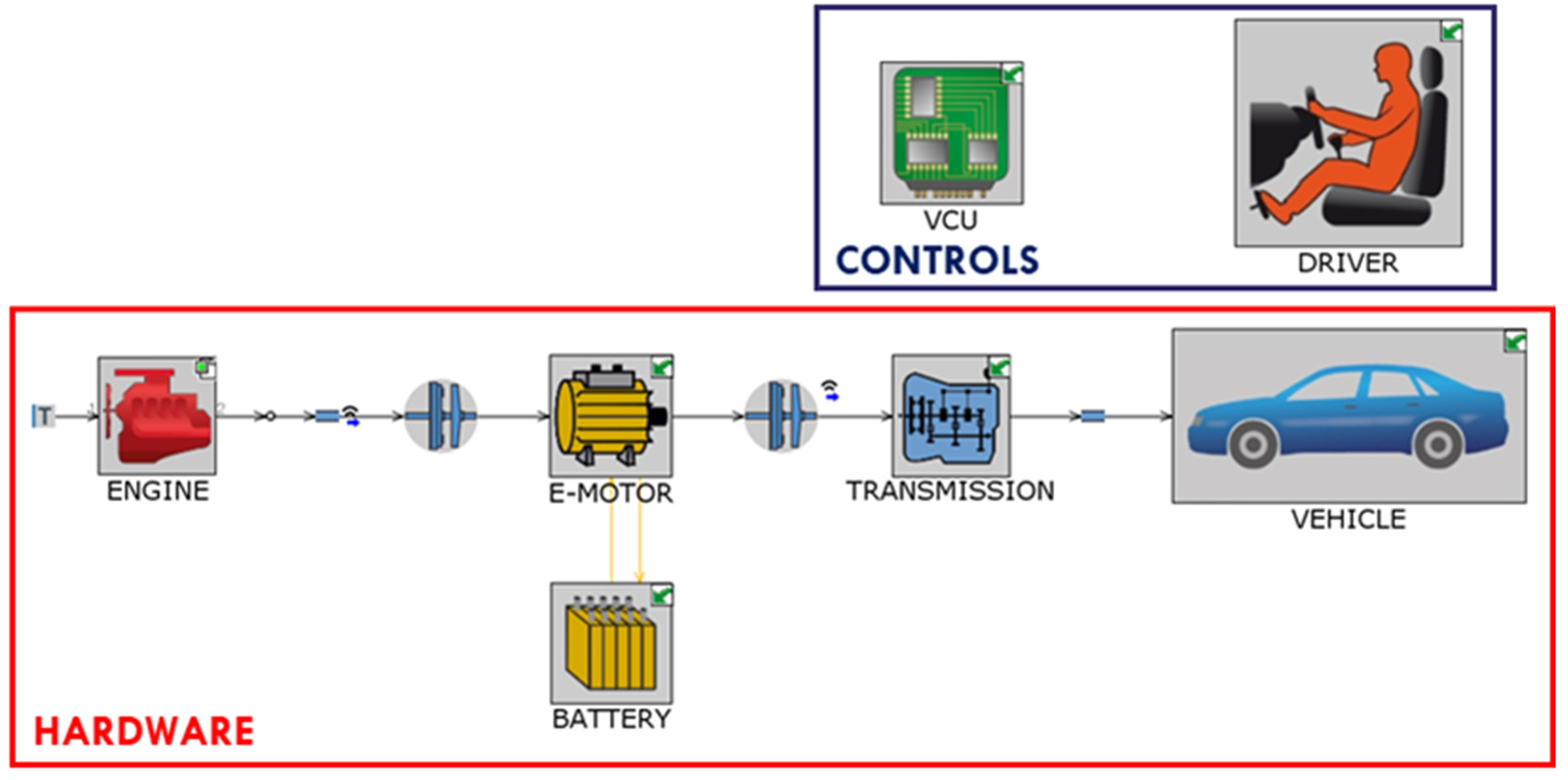
The vehicle model was built in the commercial software GT-SUITE and is schematically depicted in
Figure 1. A 0D mechanical model has been chosen for the modelling of the vehicle and driveline. The vehicle is characterized by its aerodynamic drag coefficient and frontal area, rolling resistance, test mass and the inertias of driveline and axles. Brakes are modelled with a map-based approach: brake torque is applied to the axles as a function of vehicle speed and brake pedal to guarantee the requested vehicle deceleration.
The internal combustion engine and the electric motor were represented by means of a map-based approach: fuel consumption and electric losses as a function of engine or motor speed, respectively, and requested load were looked up to compute instantaneous fuel consumption and electric power requested to the battery pack.
The battery pack was modelled with open access data for a Li-Ion battery pack [
14], scaled to achieve the requested voltage level, as an equivalent dynamic electric circuit with open circuit voltage, internal resistance and two Thevenin resistance and capacitance branches. The electric circuit is modelled with a high potential node and a ground node where the electric motor, the battery and the auxiliaries are connected.
The two clutches were modelled with a Coulomb Dry Friction model. The first one was placed between the Internal Combustion Engine (ICE) and the Electric Motor (EM) and the second one between the EM and the transmission. These two clutches were controlled in such a way to enable electric driving, hybrid mode (ICE and EM mechanically linked to the wheels) and a smooth start-up of the engine.
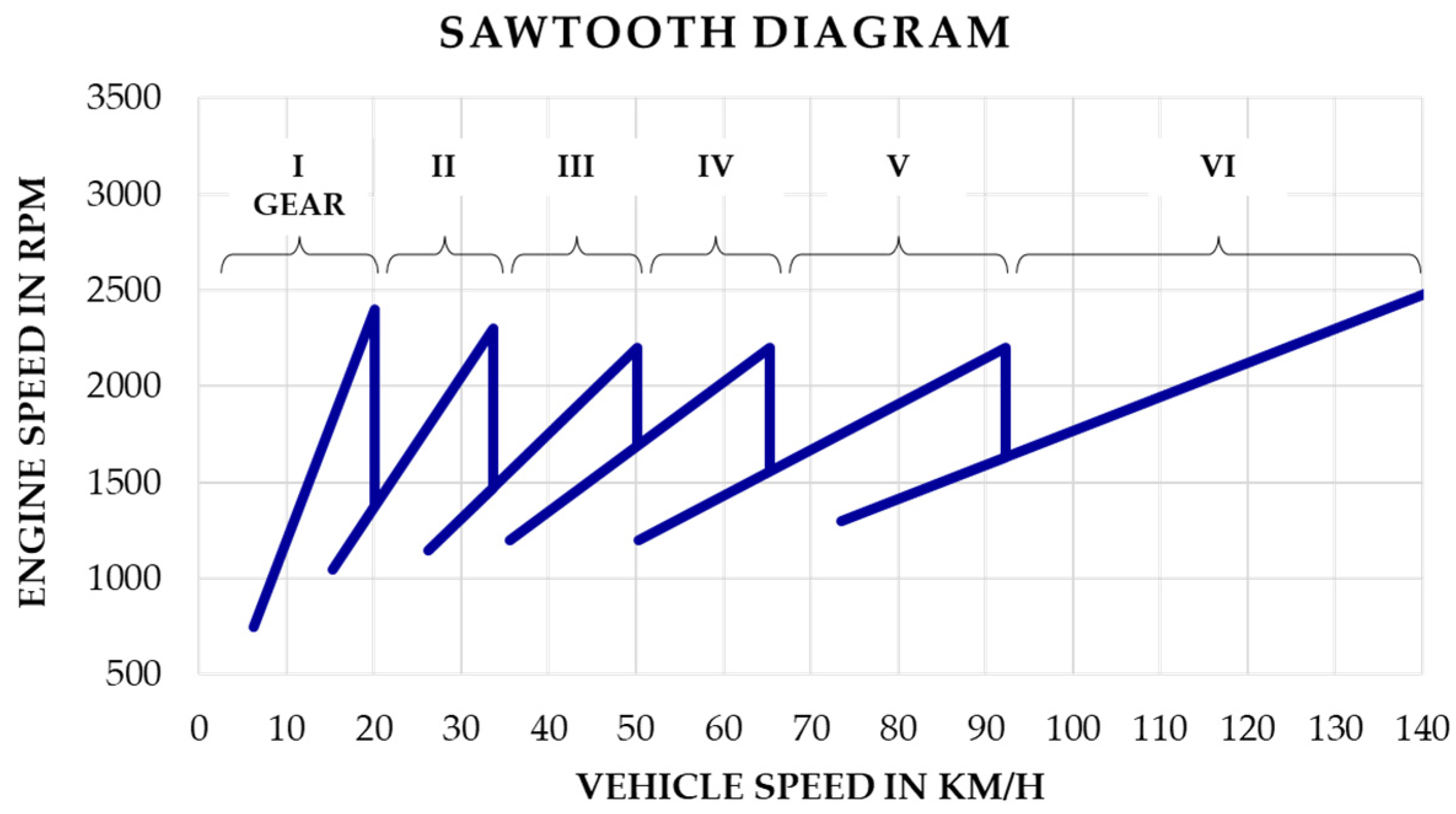
The transmission is defined by six gear ratios and a final drive with their mechanical efficiency. The gear shift is imposed on NEDC according to UNECE 83 [
15] and on WLTC and RTS-95 according to [
16], computed by means of the Gearshift calculation tool publicly available [
17], while following RDE driving cycles (i.e., RDE and City2City) a gearshift strategy based on powertrain speed was followed. The relation between powertrain speed and vehicle speed for this gearshift strategy is reported in the so-called Sawtooth diagram in
Figure 2.
The computational time of the vehicle model is lower than a tenth of the real time (0.1 RT).
2.2. Vehicle Controllers
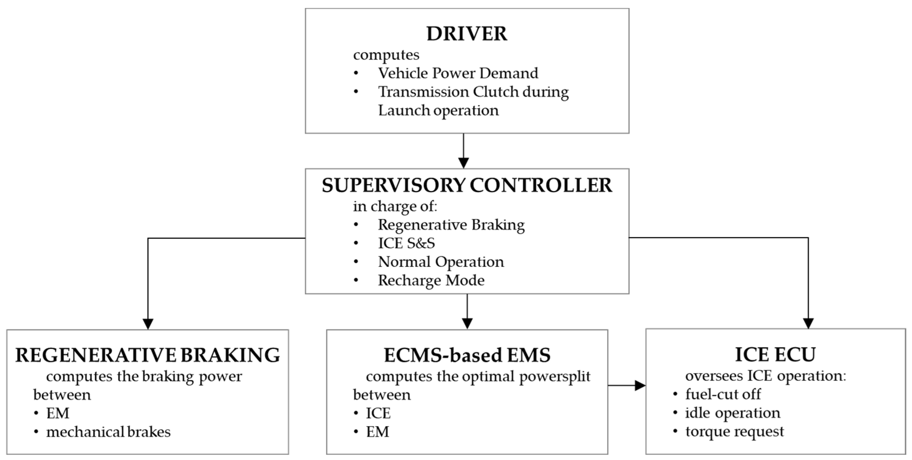
In
Figure 3, the virtual Vehicle Control Unit (VCU) integrated into the vehicle model is reported. The VCU is composed of a Supervisory Controller, an Energy Management System (EMS) based on the Equivalent Consumption Management Strategy (ECMS), a regenerative Braking controller and an Engine Control Unit (ECU). First, a driver model, modelled as a PI controller, computes the driver power demand necessary to guarantee that the prescribed speed profile (as a function of time) is followed by the vehicle. The driver power demand is later processed by the Supervisory Controller, which chooses the vehicle operating mode: when the driver power demand is negative, the ICE is switched off and the braking power is split between the electric motor, which recovers the kinetic energy to recharge the battery, and the mechanical brakes. When the driver power demand is positive, the vehicle operates in normal operation and the optimal power-split between ICE and EM is chosen; when the SOC is lower than a given threshold, the powertrain is forced to recharge the battery.
During the first phase of ICE restart, the EM acts as a starter, the transmission clutch is open and the clutch between the ICE and the EM closes at a prescribed rate. The transmission clutch is later controlled to guarantee a smooth ICE start-up. To prevent frequent oscillation of ICE power requests, a minimum ICE operation time of 10 s is required after an engine start-up. The ICE-specific control functions (i.e., start-up, fuel cut-off, idle operation, and torque request) are demanded by a virtual ECU.
Moreover, the controller which defines the power-split between ICE and EM is the ECMS-based EMS. This controller manages the multiple sources of energy on the HEV (namely the energy from the fuel tank and that stored in the battery) to instantaneously optimize the power-split and thus achieve the lowest possible fuel consumption in any circumstance. For this work, the Equivalent Consumption Minimization Strategy (ECMS), which has proven itself to be viable from an industrial point of view [
18,
19], has been chosen. In the ECMS, at every time instant, the cost function representative of the equivalent fuel consumption is minimized according to the cost function reported in Equation (1).
The equivalent fuel consumption is the sum of engine fuel consumption () and a fictitious “virtual” fuel consumption () associated with the power coming from the battery (), based on the assumption that the energy stored in the battery must be replenished using fuel energy. The parameter used to convert battery energy into fuel energy is the so-called equivalence factor , which, differently from the notation commonly available in the literature, is here reported as , which includes the Lower Heating Value (LHV) of the fuel. To implement an ECMS strategy in a dynamic vehicle model in GT-SUITE, co-simulation with MATLAB Simulink is usually employed, performing an online optimization of the traction power split between the electric machines and the ICE. In this work, a map-based power-split optimization was used instead, a technique that enables a standalone GT-SUITE-only simulation. An off-line optimization tool was used to generate power-split maps as a function of driver total power demand and equivalence factor , minimizing the overall equivalent fuel consumption upfront. The aforementioned tool was developed in the form of a MATLAB routine with a user-friendly GUI and accounts for E-Motor, ICE, and battery limitations. As an output from the offline optimization software, maps are stored in a ready-to-use GT-SUITE model that can be opened and edited by the simulation engineer.
3. Auto-Adaptive ECMS Techniques
3.1. Background
The Equivalence factor
is the key to ECMS performance. First,
is a synthetic value used to estimate the average chemical to electric conversion efficiency. It is representative of past, present and future efficiency and affects charge sustainability and the effectiveness of the strategy [
3]. Usually, the equivalence factor
is calibrated on a type-approval driving cycle to guarantee charge sustaining operation with an iterative procedure (it is not possible to analytically compute the value of
beforehand). This assumes the a-priori knowledge of the mission profile (i.e., this is not the case for Real Driving Emissions tests) and a calibration of this parameter to achieve charge sustaining operation (usually involving several iterations due to the non-linear behaviour of the power-split as a function of the equivalence factor). As a result, a fixed equivalence factor guarantees charge sustaining operation and close to optimal results in a short and specific type-approval test. However, on long and high-varying load mission profiles, a single
may produce imbalance in the SOC profile, jeopardizing the advantages of a hybrid architecture.
For these reasons, in the literature several methods to adapt the equivalence factor in a driving cycle are proposed. They can be divided in three main areas:
ECMS: the equivalence factor K is adapted using the SOC feedback;
Driving Cycle Recognition (DPR): the equivalence factor K is chosen from a subset of equivalence factors as a function of past vehicle driving pattern (i.e., velocity trace);
Driving Cycle Prediction (DPP): the equivalence factor K is chosen from a subset of equivalence factors as a function of past and future vehicle driving patterns (i.e., velocity trace).
For online implementation, the SOC feedback is always necessary, and therefore it is also used for DPR and DPP, even if it is not the main adaptation variable [
5].
3.2. Adaptation of K Using the SOC Feedback (A-ECMS)
Different methods can be adopted for the adaptation of the equivalence factor in order to guarantee limited variations of the SOC and optimal results. These methods are:
Continuous A-ECMS with Proportional controller [
6].
This is a simple proportional controller, represented by Equation (2):
where
is the equivalence factor computed at each time instant,
is the initial
K factor,
is the proportional term,
is the target value for the battery SOC and
is the actual SOC value. The
is usually pre-determined to guarantee room to discharge or recharge the battery. For this reason, in this work it is assumed to be equal to 0.5 (the nominal SOC of the battery at the beginning of the simulation).
Continuous A-ECMS with Proportional Integrative controller [
7,
8].
This is a modified version of the proportional controller to guarantee improved performance when tracking the battery SOC:
where
is the integrative term.
Discrete A-ECMS—Autoregressive Moving Average (ARMA), with adaptation at discrete intervals
T [
9]:
The current equivalence factor is computed based on the equivalence factors computed at two previous time interval and the battery SOC, according to Equation (4). At each update interval
, the equivalence factor
is updated as a function of the difference between the actual SOC and a target SOC. Additionally, the two autoregressive terms accounts for previous states of the equivalence factor:
where
is the equivalence factor computed at the beginning of interval
and adopted throughout the interval,
and
are the
factors computed at the two preceding intervals,
is the proportional term,
is the target value for the battery SOC and
is the one at the beginning of the current time interval
.
This discrete A-ECMS allows a greater utilization of the battery SOC within the interval T, also termed as adaptation time (Tadapt). For this reason, this solution was developed and integrated in the GT-SUITE model. Because the may have a significant impact on charge sustainability and optimality of the solution, it has to be calibrated. In this work, the was calibrated to achieve a satisfactory trade-off across different driving cycles; a unique value for all the five driving cycles investigated was eventually chosen.
3.3. Driving Pattern Recognition (DPR-ECMS)
The equivalence factor K is the only calibration parameter of the ECMS and defines the optimality of the solution and charge sustaining performance. When the vehicle is operated on driving cycles which are different from the driving cycle used for the calibration, the performance of the ECMS may worsen significantly. The idea behind the Driving Pattern Recognition is that various driving cycles can be classified according to some general metric. Then, during vehicle operation, these driving patterns can be recognised, and the proper equivalence factor K can be selected to guarantee charge sustainability on a wide range of operating condition.
In this work, the methodology proposed by Gu et al. [
10] was followed, and a DPR-ECMS controller was developed in Simulink and integrated in the GT-SUITE model with a Simulink Harness.
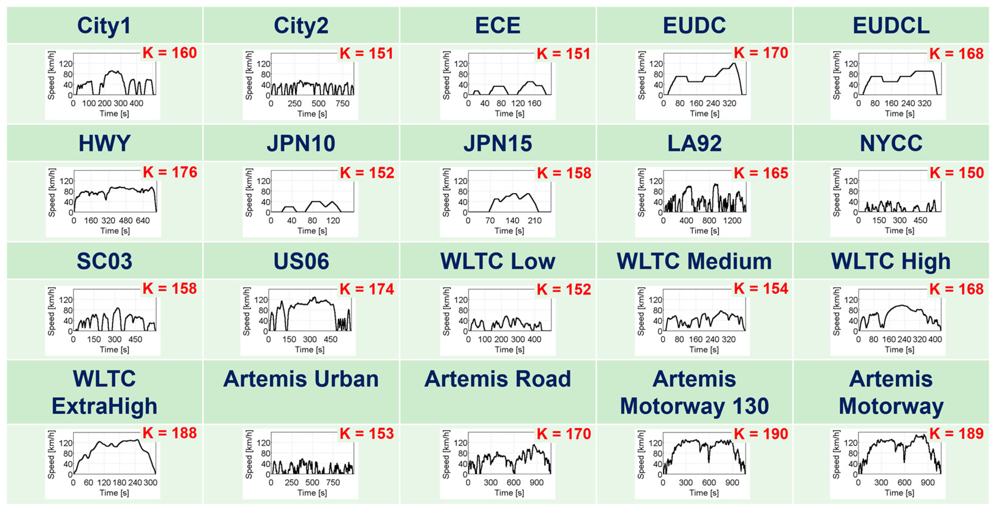
First, the recognition capabilities of the DPR-ECMS controller were set up. For this reason, 20 non-repetitive, non-composed type-approval driving or standard driving cycles were chosen. Standard and type-approval driving cycles were gathered from different sources [
17,
20]. For example, because the NEDC is composed of three repetitions of the ECE and the EUDC, the NEDC is decomposed in an ECE and an EUDC driving cycle, while the WLTC utilises the Low, Medium, High and Extra-high sections. Then, for each driving cycle the charge-sustaining equivalence factor
K is assessed via an iterative method (see
Figure 4).
Techniques have been developed to analyse and cluster different driving cycles [
21,
22]. In this work, among 21 statistical metrics computed for each driving cycle (e.g., mean run velocity, maximum acceleration, cruise fraction), only 18 statistical metrics (duration, distance and the number of stop per unit distance were considered of limited interest and excluded) were used for the driving cycle classification, as performed by Gu et al. [
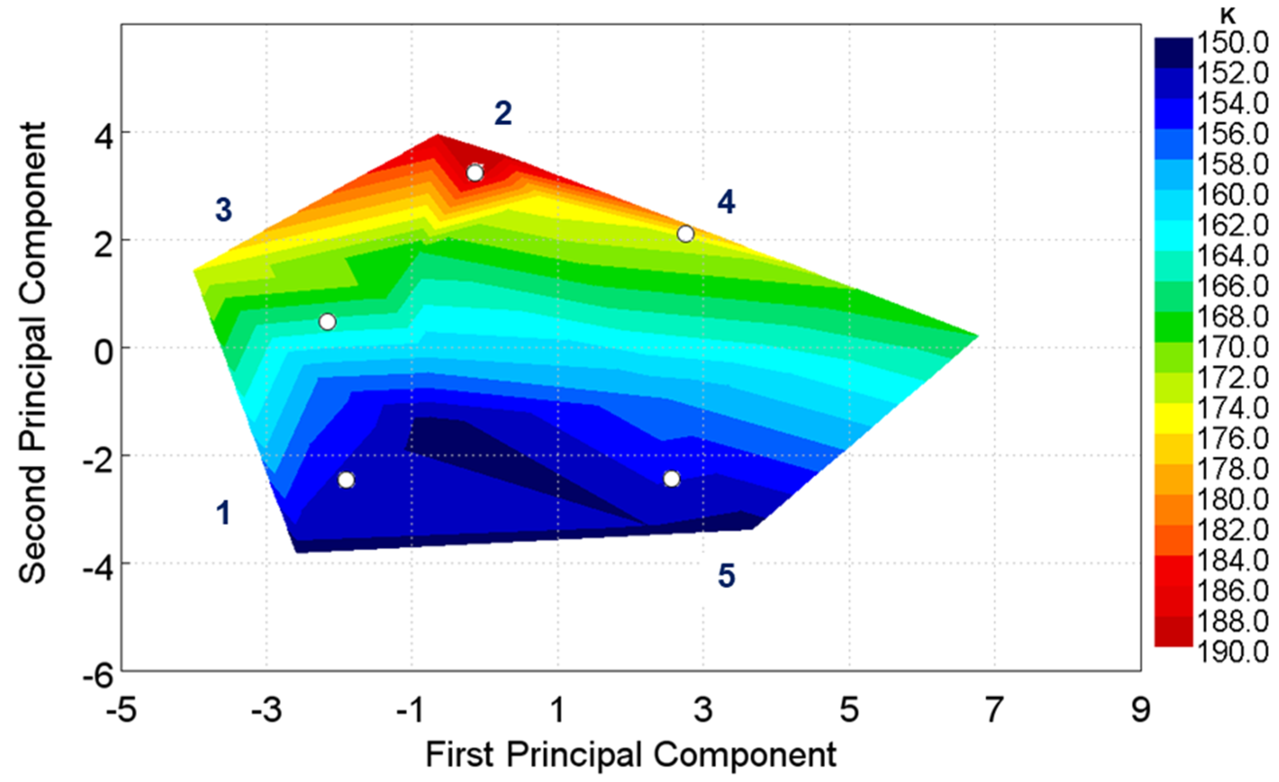
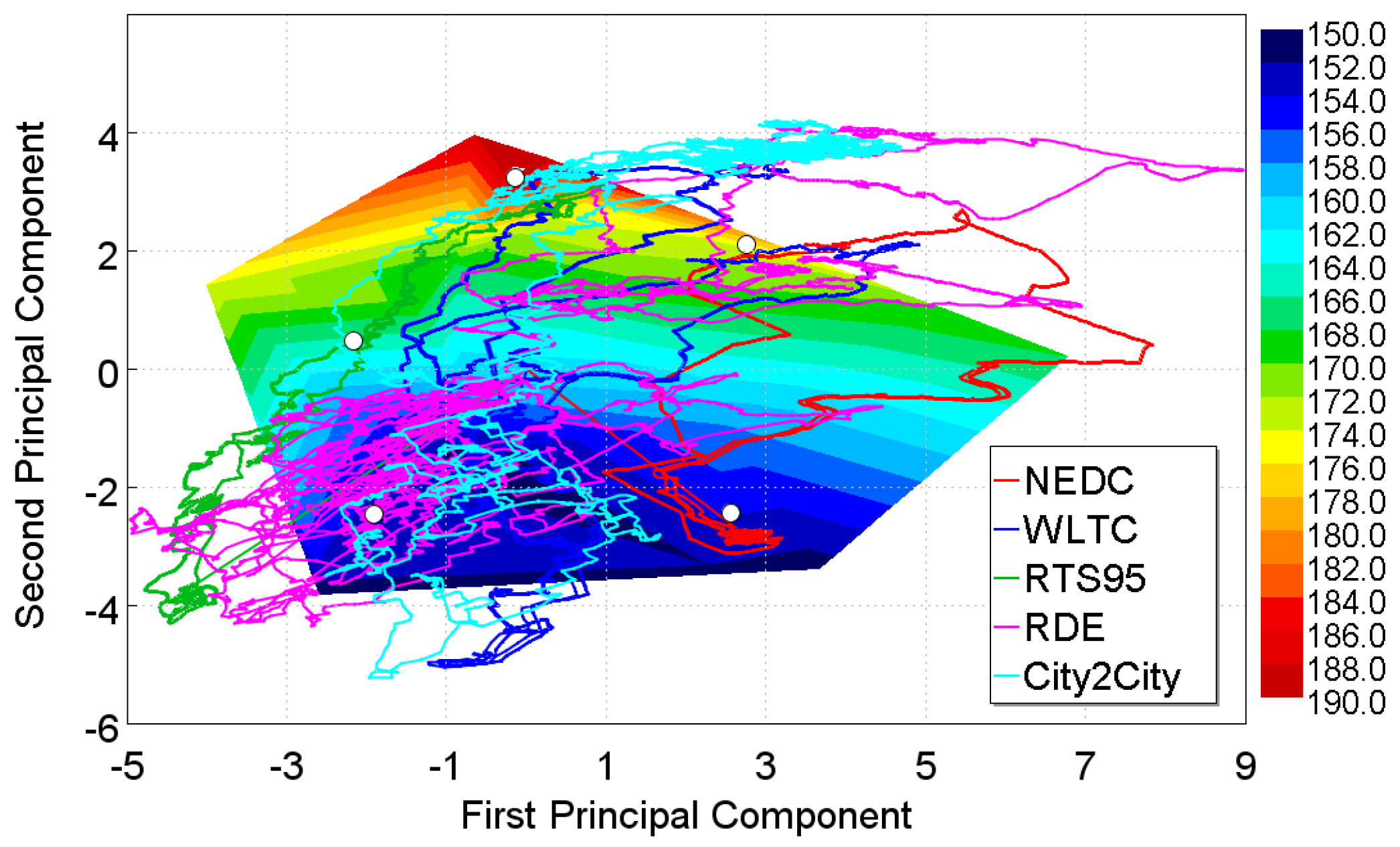
10]. Then, Principal Component Analysis (PCA) was used to reduce the numerosity of the data; four principal components were chosen which described 95% of the variance of the dataset. To improve the classification, the LA92 driving cycle was excluded from this analysis because it includes mixed driving conditions (urban and suburban). The remaining driving cycles were grouped into five different driving clusters, as represented in
Figure 5, by a
K-means algorithm [
23]. These driving clusters were representative of, for example, urban, extra-urban or highway driving style. From this classification, the WLTC Medium section driving cycle was removed because its
K was an outlier on the PCA plan and could not effectively be included in a specific driving cluster. Finally, the average equivalence factor of the driving cycles belonging to a certain cluster was computed and assigned to each driving cluster. The driving clusters with their specific equivalence factor
K are reported in
Table 2.
During vehicle operation, the driving metrics of the last 200 s of vehicle velocity are, instant by instant, computed. The driving metrics are then transformed to PCA coordinates, and after the identification of the closest cluster, the driving pattern is recognized. Then the equivalence factor of this driving pattern is used to select the optimal power-split.
To account for significant off-design mission profile, for example altitude variations, a PI controller on top of the DPR is adopted. This PI controller is analogous to the one presented by Gu et al. [
10].
3.4. Driving Pattern Prediction (DPP-ECMS)
Only the previous 200 s were analysed during vehicle operation by the DPR controller. Thus, the equivalence factor adopted was late up to a certain extent, worsening the theoretical performance of the controller. In this section, the DPR controller is updated to a DPP controller able to recognize a driving pattern which comes from both past and forecasted vehicle velocities.
In the literature, different implementation of the predictive capabilities of HEV controllers have been proposed. Musardo et al. developed an adaptive ECMS based on both past and predicted vehicle speed [
24]; when the equivalence factors must be updated, the algorithm first builds the current mission combining past and predicted vehicle speed and GPS data, then determines the equivalence factor that minimizes fuel consumption. Sciarretta et al. [
25] based the online estimation of the equivalence factor on a look-ahead horizon defined in terms of energy at the wheels, thus measurements are used to determine, at each instant, the most likely behaviour (charging or discharging). Ambuhl et al. [
11] developed a controller where the adaptation scheme used a predictive Reference Signal Generator (pRSG) in combination with an SOC tracking-based controller (implemented in the form of feedback from SOC). The pRSG computes the desired battery SOC trajectory as a function of vehicle position to maximize recuperated energy. In this case, the topographic profile of the future road segments and the corresponding average traveling speeds must be known. Fu et al. [
12] used a Model Predictive Control (MPC) based strategy and utilized the information attainable from Intelligent Transportation Systems (ITS) to establish a prediction-based real-time controller structure.
The past works were intended to build a comprehensive controller able to predict future driving profiles and choose the optimal equivalence factor
K. On the contrary, in the present work, the aim is to enhance the performance of the DPR controller already developed, adding the capability to predict or estimate future velocity. From this perspective, different methods can be followed [
26]: Exponentially varying, Markov-Chain or Neural Network velocity predictors. These latter showed the best overall performance across a range of certification and real-world drive cycles in the works done by Liu et al. [
13,
27], where different prediction methods were analysed and a Long Short-Term Memory (LSTM) Deep Neural Network Model was finally selected in combination with CAN data, radar, GPS and current velocity on a 10 s velocity prediction for the energy management of a complex HEV.
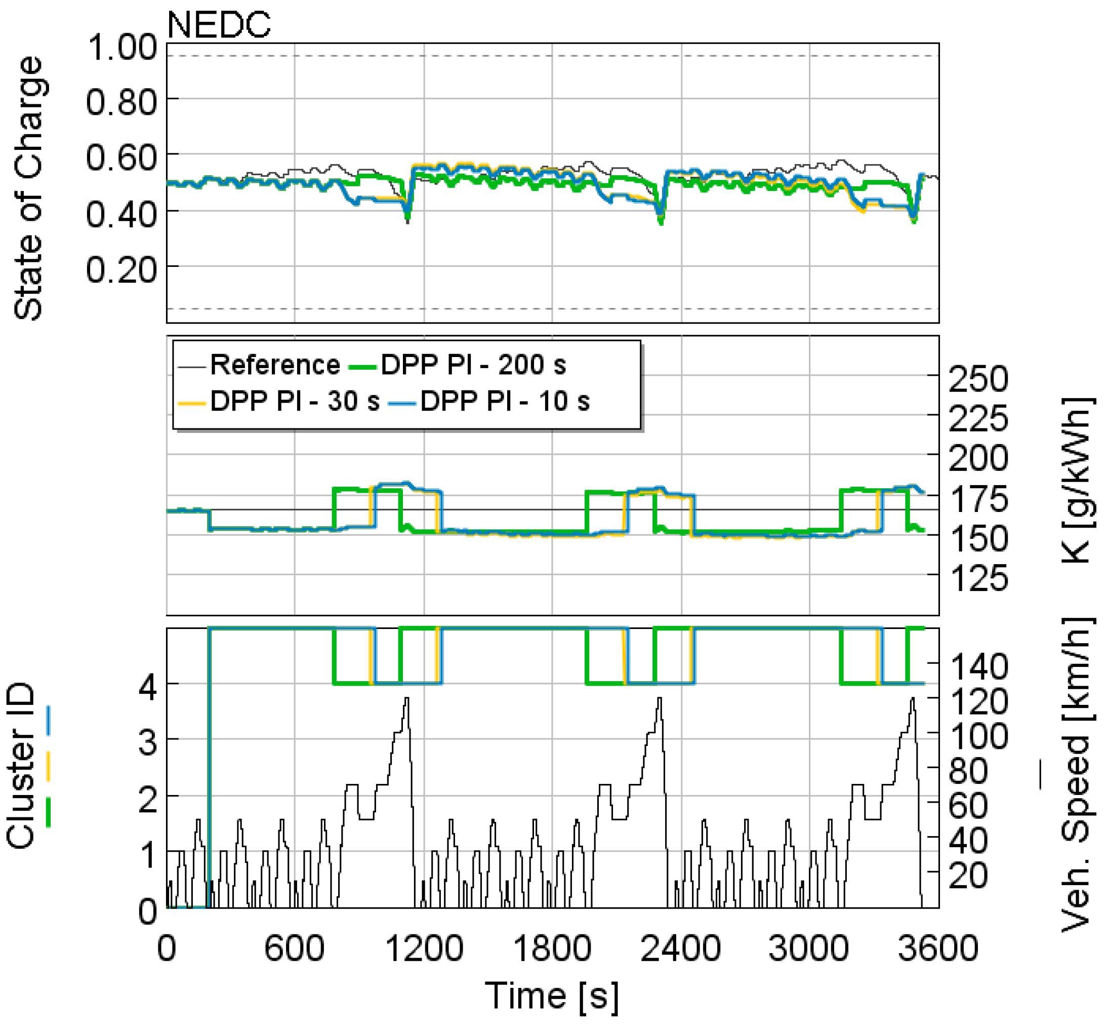
In the current work, different prediction techniques were assessed. First, the performance of a DPP controller able to estimate the exact future driving profile (using type-approval driving cycles) with three prediction intervals (200 s, 30 s and 10 s) was evaluated. Because the rolling windows taken into account for the Driving Pattern Recognition is equal to 200 s, depending on the prediction interval, only future or various fractions of past and future velocities are used to estimate the driving cluster. When the duration of the recognition interval and of the prediction interval were equal (i.e., prediction interval of 200 s), a reference point was set. This benchmark, representative of the maximum benefit attainable by a recognition controller with the perfect knowledge of a future driving profile, is used to compare different prediction models. The closer to the benchmark a prediction model gets, the higher its forecast quality. Because in real life the Perfect Prediction on long time intervals may be hardly attained due to unpredictable traffic situations, two tests with shorter intervals of Perfect Prediction (i.e., 30 and 10 s) were proposed. These DPP controllers were termed as Perfect Prediction DPP and the acronyms DPP-PP200, DPP-PP30 and DPP-PP10, referring to the forecast window of 200 s, 30 s and 10 s, respectively, were adopted.
Then, two simple prediction models were assessed. The first prediction model is called Persistence Model (DPP-PE) and assumes that nothing changes in the velocity profile, thus the velocity profile in the forecast interval is equal to the velocity of the last timestep. The second prediction model, termed as Exponential Model (DPP-EX), is instead based on the exponential decrease of the vehicle velocity according to the following equation [
26]:
where
is the forecasted velocity at the time
of forecast,
is the current vehicle velocity,
is the time of forecast (from 1 s to the maximum forecast duration, i.e., 30 s). The forecast velocity in the early phases of the NEDC for these two prediction models are reported in
Figure 6.
4. Test Matrix
The auto-adaptive EMSs developed or analysed in this work are representative of four different case studies:
a reference vehicle with a fixed equivalence factor ECMS;
a vehicle featuring auto-adaptive ECMS with SOC feedback;
a vehicle featuring the auto-adaptive ECMS based on Driving Pattern Recognition (DPR);
a vehicle featuring auto-adaptive ECMS based on Driving Pattern Prediction (DPP).
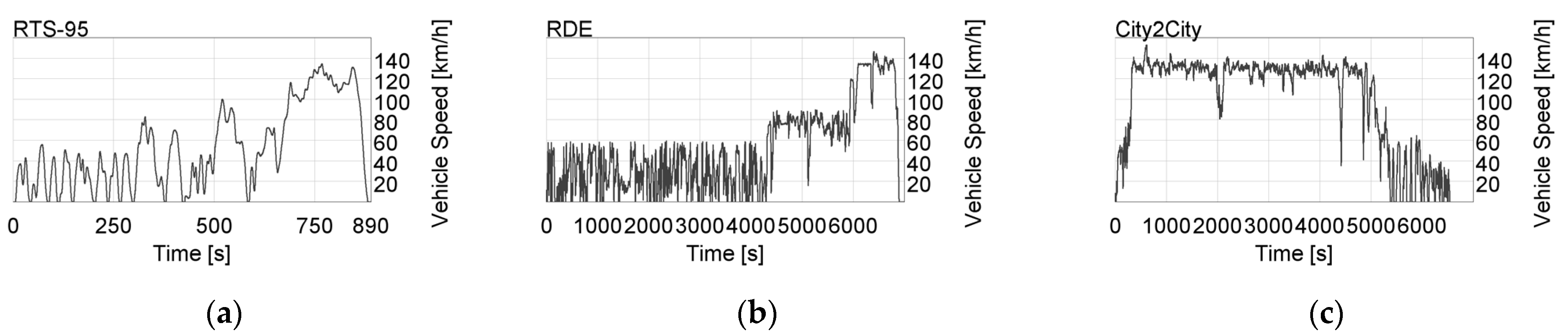
These case studies were tested using different driving cycles, both type-approval (NEDC, WLTC) and RDE driving cycles (RTS-95 and two customer driving cycles defined as RDE and City2City). Although the NECD has lately been phased-out, it is taken into account in this work for various reasons: it is fundamental for benchmark analysis with relatively recent vehicle architectures; it is composed by constant acceleration and constant speed phases, therefore it is useful to evaluate the stability of models and controllers in a defined scenario; because the cycle energy requirement is low, the NEDC combined with other driving cycles offers an extended assessment of controllers and vehicle architectures. The type-approval or standard driving cycles have been iterated several times to assess the performance of adaptive ECMS techniques over a longer timeframe (20 or 5 times for the A-ECMS based on SOC feedback, 3 times for DPR-ECMS and DPP-ECMS).
In
Figure 7, the RDE driving cycles are reported.
The aim of adaptive controllers is to ensure charge sustainability during real driving operation. In this context, different boundary conditions may apply. For example, if the car is parked for a long period of time, the battery may be depleted or, during winter, high electric power may be drawn by the rear defroster. Although multiple driving factors are impacted by a real driving cycle [
28], to test these auto-adaptive strategies in off-design conditions, a reduced sensitivity analysis concerning the auxiliary power (0–500 W) and the initial SOC of the battery (0.2–0.8) was performed. Moreover, for the A-ECMS based on the SOC feedback only, different initial values of equivalence factor
K were tested.
The A-ECMS based on Driving Pattern Prediction is assessed considering Perfect Prediction (DPP-PP), Persistence Model (DPP-PE) and Exponential Model (DPP-EX) with different timeframes of prediction interval. The Perfect Prediction is in fact investigated with a prediction interval of 200 s (DPP-PP200) to reproduce a theoretical case of 30 s (DPP-PP30) and 10 s (DPP-PP10). The Persistence Model (DPP-PE) and the Exponential Model (DPP-EX) were tested at 30 s because this is a rather acceptable prediction time interval when ADAS systems are taken into account.
5. Results
In this section, the results of the three auto-adaptive ECMS strategies are reported.
5.1. Adaptation of K Using the SOC Feedback (A-ECMS)
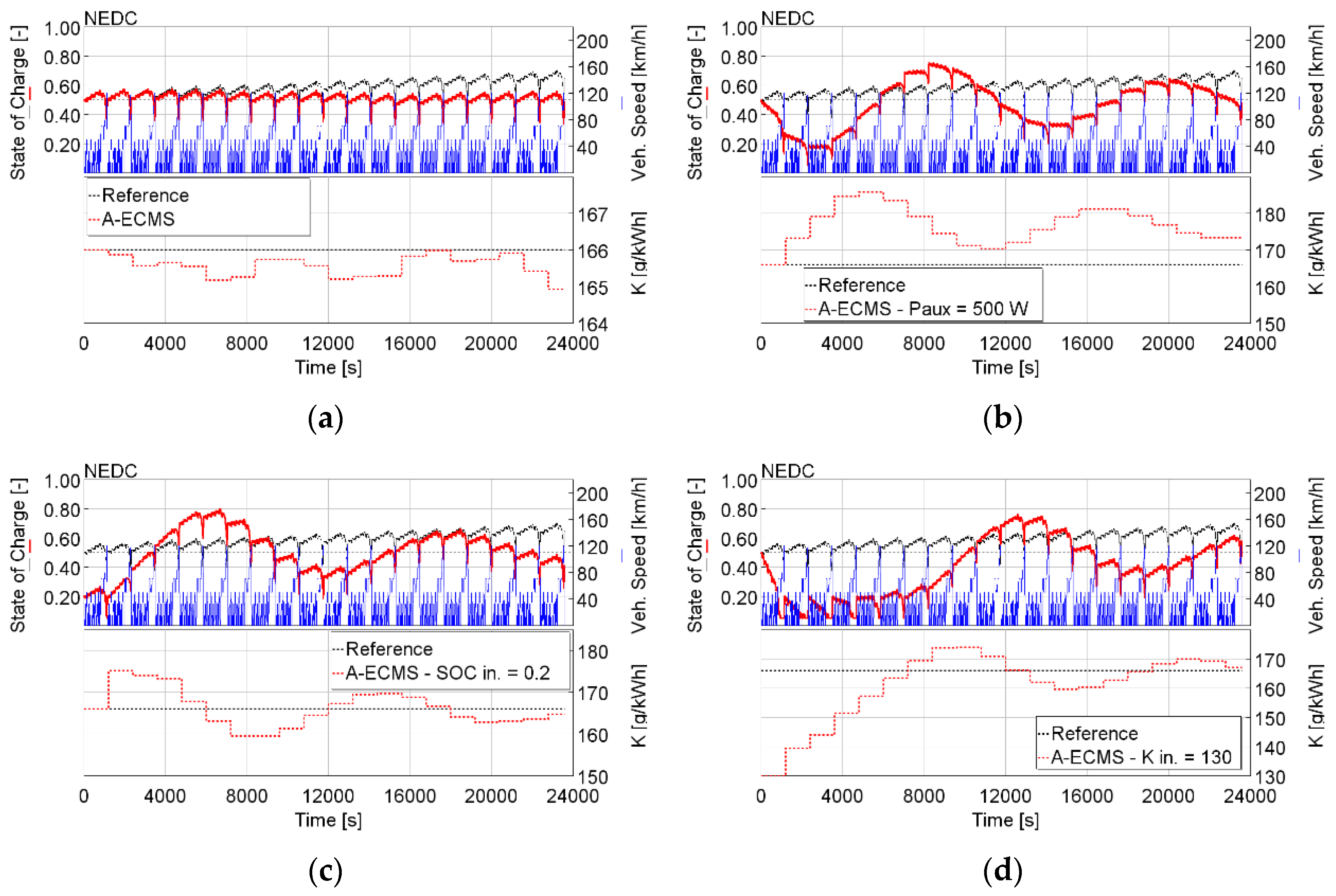
Concerning the so-called Autoregressive moving average, when the update time interval is equal to the length of the cycle, this filter can be used as an optimizer. In
Figure 8, the performance of this method is reported using NEDC for a reference case and three off-design conditions. In this way, possible deviations of the SOC over a large timeframe are counterbalanced by the update of the equivalence factor, and the SOC is driven towards its target. The A-ECMS showed the capabilities to converge towards the optimal equivalence factor
K after some repeated driving cycles, achieving a comparable fuel consumption with respect to the reference case, with limited SOC swing. End-of-cycle SOC is close to the target SOC and, after 20 cycles, A-ECMS proved to guarantee a stable SOC behaviour (SOC drifts are noticeable on the reference case with constant
K). The calibration of
Cp was performed in order to guarantee that the optimal
K is achieved before 20 cycles with limited controller overshoot in the NEDC, as depicted in
Figure 7, WLTC and RTS-95.
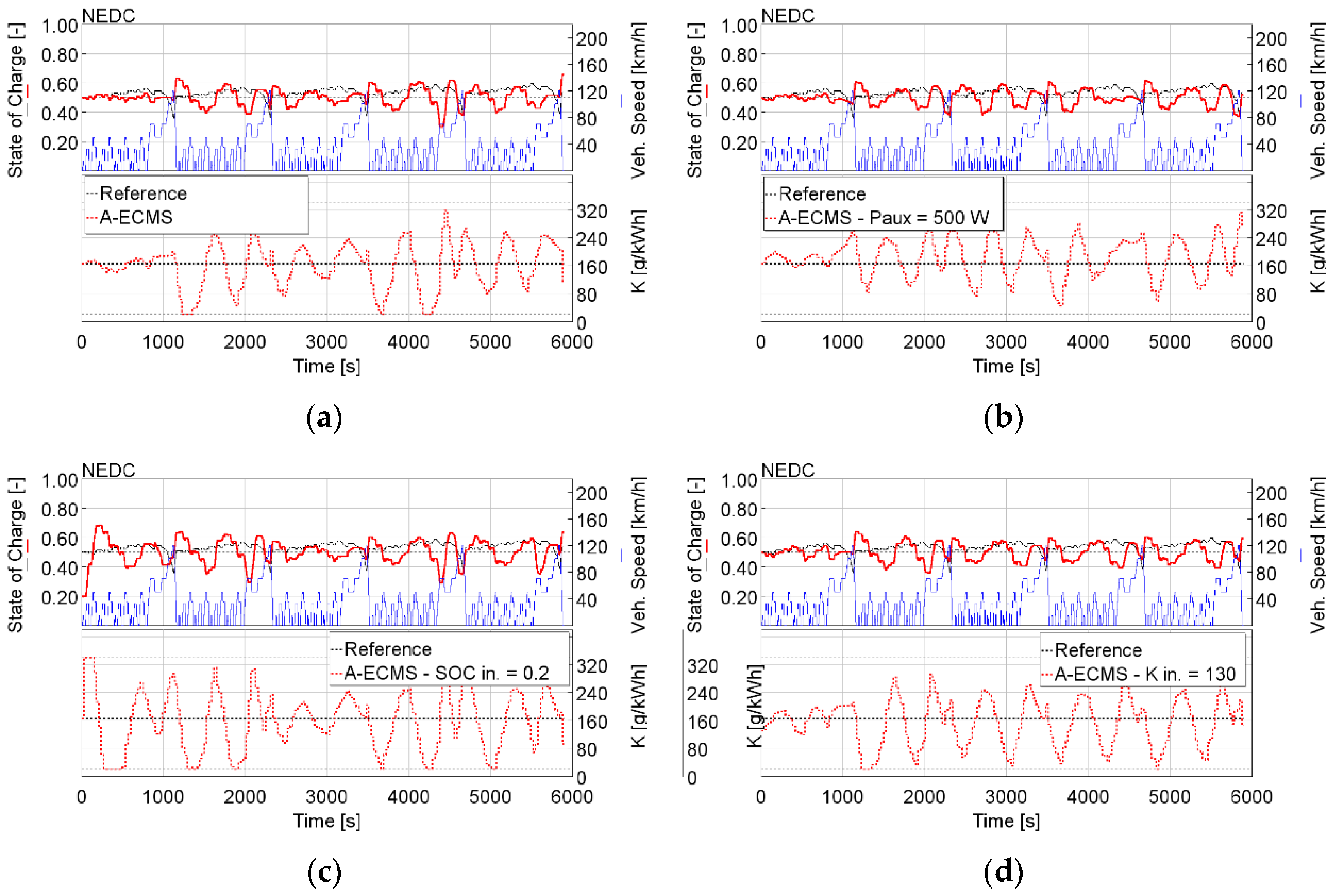
When the aim is instead to have a reasonable controller that can be implemented in an ECU, the adaptation time must be smaller than the driving cycle duration. For this reason, an adaptation time equal to 30 s and a
Cp equal to 630 were adopted in all the driving cycles of interest. In this case, the EMS is able to maintain a State of Charge between 0.4 and 0.6 for the majority of the simulations, and it is able to account for the increased auxiliary power or a low starting SOC or a low initial equivalence factor
K (
Figure 9).
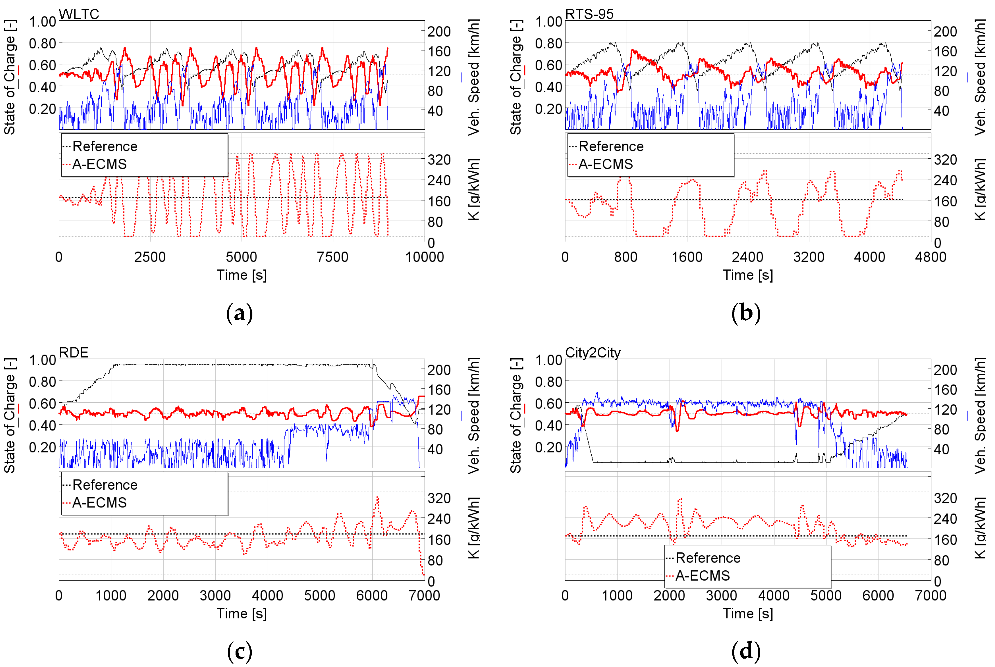
In
Figure 10, the performance of the Adaptive ECMS calibrated with a fixed
Cp and adaptation time is reported on WLTC, RTS-95, RDE and City2City. While on WLTC and RTS-95, the SOC is maintained between 0.2 and 0.8 and the oscillation of the equivalence factor
K is quite high. This is due to the fact that the RDE driving cycles required a reduced adaptation time so that the controller could counteract steep variations in the power demand from the battery. Moreover, the
Cp was chosen in order to have the smallest possible variation of the battery State of Charge. The RDE-Capable AECMS was able to operate the vehicle, maintaining the battery SOC around the target. The calibration of
Tadapt and
Cp was performed in order to limit the SOC swing in the NEDC, WLTC, RTS-95, RDE and City2City cycles. In this work,
Cp coefficients, as a function of the vehicle speed, were not taken into account, but they might stabilize the controller itself.
The RDE-Capable AECMS was demonstrated to improve the fuel consumption on RDE cycles with respect to a ECMS based on a fixed K. In fact, a fixed K would result, at some point, in the full charge, or the complete depletion of the battery, as seen on the RDE and City2City cycles, respectively. In these cases, the performance of the HEV is reduced because, when the battery is fully charged, no energy can be recovered by regenerative braking while, when the battery is discharged, the electric motor is not able to assist the internal combustion engine.
CO2 emissions are directly computed from the fuel consumption without considering the difference in terms of battery SOC between the beginning and the end of the driving cycle. RDE legislation does not require that CO2 emissions are corrected and, on long cycles (or multiple type-approval cycles), the impact of the added or depleted energy in the battery on fuel consumption becomes negligible.
The results, in terms of CO
2 emissions and final battery SOC from the adoption of the ECMS calibrated for all the driving cycles, are reported in
Table 3. It is to be said that the results in terms of CO
2 emissions were not corrected as a function of the final battery State of Charge. This correction procedure is required by legislation for type-approval driving cycles and for significant difference in battery SOC between the beginning and the end of the test. However, because the controllers assessed in this paper are aimed to operate unsupervised in different RDE driving cycles, CO
2 emissions and final SOC were both tracked and presented in the results, with no intervention; the lower the CO
2 and the lower the difference between final SOC and target SOC (equal to 0.5), the better the controller performance.
For any driving cycle, the increase of the auxiliary power is characterized by an increase in the CO2 emissions, which is around 10 g/km for NEDC, WLTC and RTS-95 with respect to the case with fixed K. The final SOC is between 0.4 and 0.6, except for the WLTC. The A-ECMS using WLTC shows increased CO2 emissions with respect to the vehicle with fixed K because the oscillations of the K factor force the powertrain to charge or discharge the battery too frequently which is far from optimal. When Paux is increased to 500 W in the WLTC, the oscillations on the equivalence factor K are reduced and optimality is achieved. The performance of the A-ECMS controller based on the SOC feedback can be appreciated in the RDE driving cycle, where an improvement of 4 gCO2/km is achieved with an increase of the battery SOC at the end of the cycle. This is due to the fact that an SOC controlled in the range of 0.4–0.7 guarantees that all hybrid functionalities are enabled (e.g., regenerative braking). This is also confirmed for off-design conditions. In the City2City driving cycle, the impact of the A-ECMS is negligible because this cycle is mainly representative of a highway driving cycle where the ICE is mainly switched on and the impact of the electric motor is limited.
5.2. Driving Pattern Recognition (DPR-ECMS)
The approach based on Driving Pattern Recognition was tested using all the driving cycles, and the results are reported in this section.
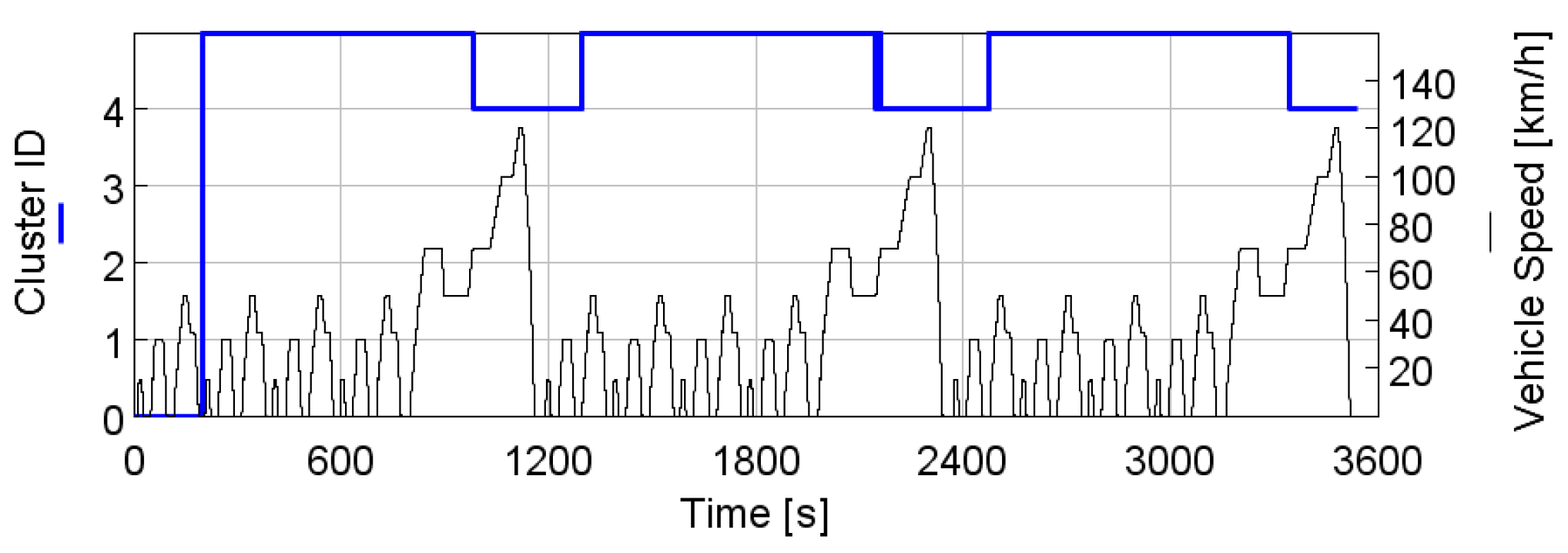
Concerning the NEDC driving cycle, in
Figure 11, the driving clusters identified by the controller are reported. The controller recognises the ECE part of the cycle as belonging to the driving pattern number 5, while the EUDC is identified as Cluster 4, as defined during the development of this controller (see
Table 2). Because the analysis of the driving metrics is performed considering the last 200 s, the recognition of the driving pattern is delayed with respect to the start of the EUCD, while during the first 200 s of the entire NEDC, the controller is initialized.
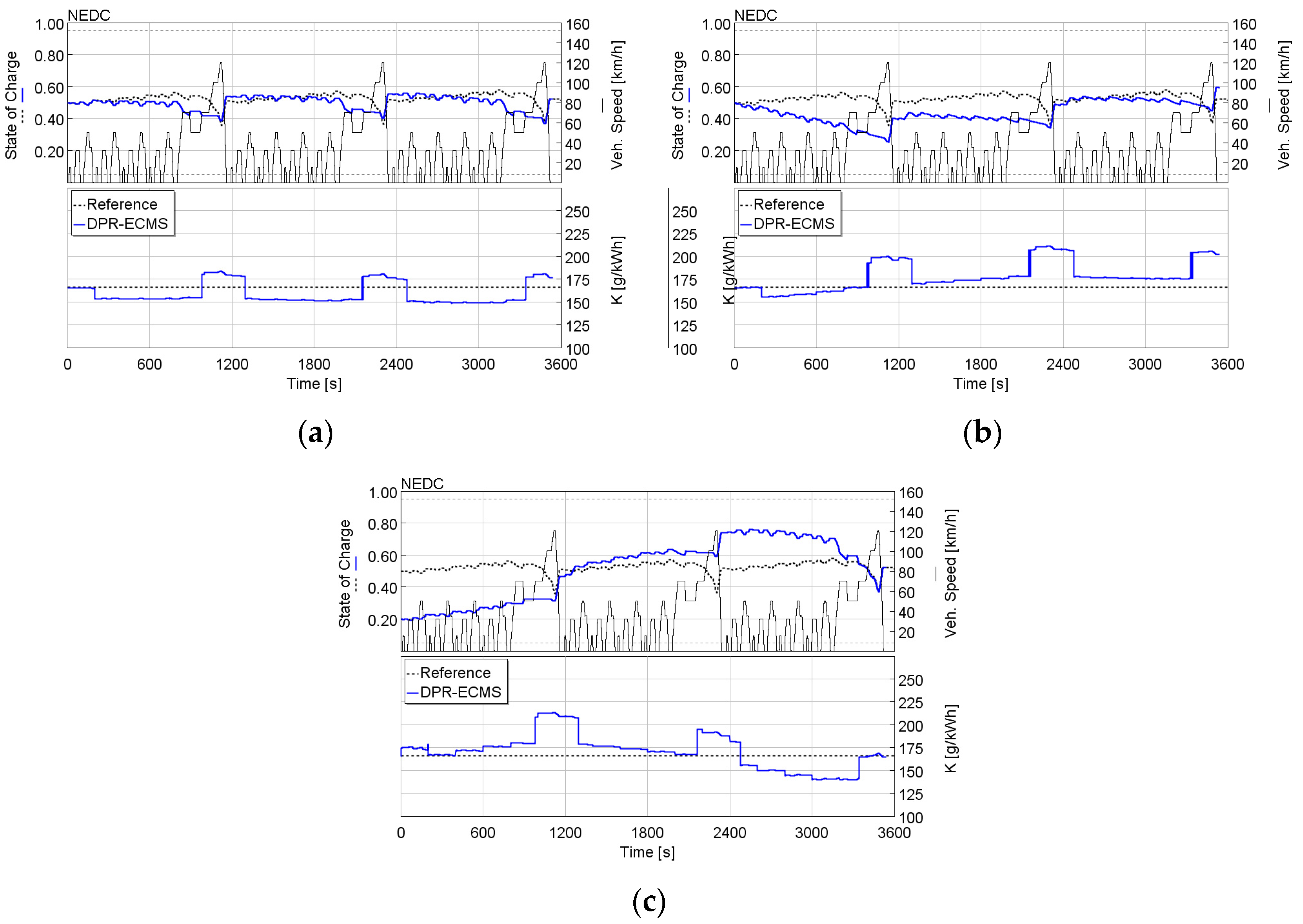
The results in terms of battery SOC and equivalence factor
K in the NEDC, for some design conditions are reported in
Figure 12. In terms of charge sustainability, the DPR-ECMS is able to achieve a final SOC close to the target. Because the recognition of the EUDC happens with a certain delay, the SOC is reduced due to a
K lower than the charge sustaining
K, and only after regenerative braking and the recognition of the ECE, is the SOC aligned with the target. When the auxiliary power is increased to 500 W or the initial SOC is far lower than the target SOC, the PI controller intervenes, in combination with the DPR, to update the
K factor above or below the
K factor of the reference case.
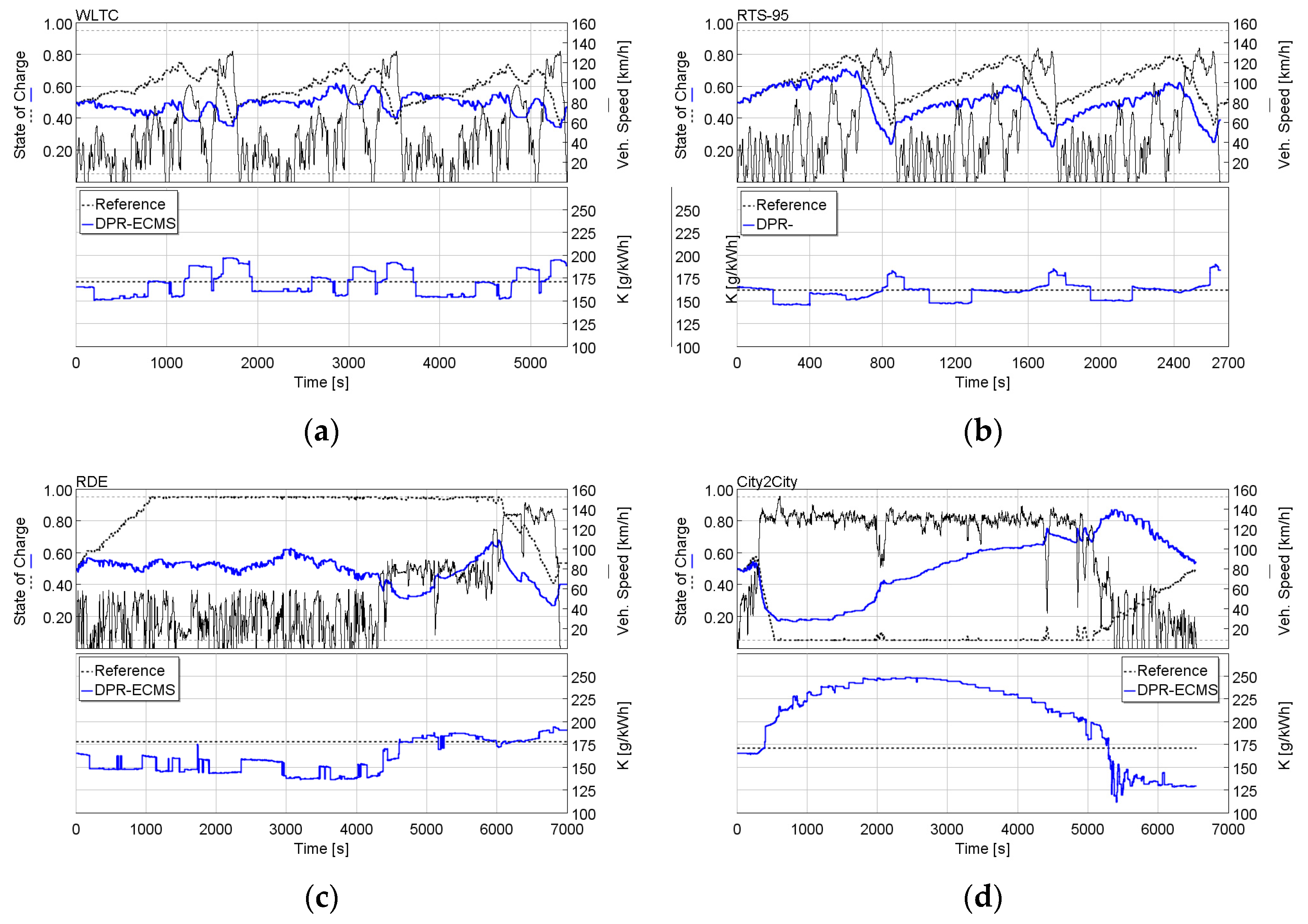
The performance of the controller using WLTC, RTS-95, RDE and City2City are reported in
Figure 13. In these cases, various clusters are recognized. In the WLTC, the deviation of the SOC of the vehicle featuring the DPR-ECMS with respect to the reference case is low. In the RDE, the SOC is controlled mostly between 0.4 and 0.6, while in the City2City the SOC is operated between 0.2 and 0.8. The City2City driving cycle is composed of a strong highway phase up to 5000 s and a mild urban phase in the last part of the cycle, which would require, respectively, a significantly higher and lower
K factor with respect to those determined during the controller development phase. The criticalities of the DPR-ECMS controller in the City2City driving cycle can be seen as a recommendation to extend, towards specific RDE driving cycles, the database of driving cycles used to build the controller.
In
Table 4, the results in terms of CO
2 emissions and final battery SOC are reported. The DPR-ECMS shows comparable or improved CO
2 emissions with respect to the vehicle featuring the fixed
ECMS using the five driving cycles investigated. In the RDE, the DPR-ECMS improves the fuel consumption by 6 gCO
2/km. The higher
Paux has an impact on CO
2 emissions, which increase by 10 gCO
2/km on NEDC, 6 gCO
2/km on WLTC, 8 gCO
2/km on RTS-95, 6 gCO
2/km on RDE and 4 gCO
2/km on City2City, and the controller guarantees a comparable battery SOC at the end of the driving cycles. Using regulated driving cycles, an initial State of Charge equal to 0.2 causes an increment of CO
2 emissions because the battery pack must be replenished during driving to achieve the target SOC, while on RDE and City2City the energy to recharge the battery is negligible with respect to the energy used to move the vehicle.
Figure 14 represents the operating conditions of the DPR controller using the five driving cycles investigated, depicted on a plot in which the X and Y axis are the first and second principal components, respectively. The five driving cycles cover the surface explored during the controller development, encompassing all five clusters identified. The components of RTS-95 and RDE roam to lower First and Second principal components than previously evaluated, while RDE and City2City (this latter for a significant portion of time) also extend to higher First and Second principal components (upper right part of the figure). This suggests that future development of the DPR controller must account for additional RDE cycles during the principal component characterization phase to improve the recognition capabilities of the controller.
5.3. Driving Pattern Prediction (DPP-ECMS)
The DPR-ECMS showed how the recognition of the driving pattern can improve both charge sustainability and CO2 emissions for a HEV. In this section, the authors evaluate the benefit coming from the prediction of future velocity traces in terms of CO2 emissions and charge sustainability with different velocity predictors.
First, the theoretical improvement coming from the exact knowledge of future velocity was evaluated using NEDC, WLTC and RTS-95 with different forecast durations (200 s being the rolling time window processed by the controller): 200 s, 30 s and 10 s. Then, two simple prediction models, the Persistence and the Exponential Model, were used to predict the future velocity trace with a forecast duration equal to 30 s using the five driving cycles chosen. In
Table 5, the acronym for each DPP-ECMS assessed is reported.
In
Figure 15, the SOC, the
K and the identified clusters using NEDC for three different perfect forecasts are represented. A forecast window of 200 s (equal to the processed velocity timeframe) brings the recognition of the EUDC cluster forward and an earlier adoption of a higher
K factor, which results in a SOC close to the target. The difference between a Perfect Prediction window of 30 s or 10 s is minor, and the performance of the DPP-ECMS controller with these settings is close to the DPR-ECMS (cf.
Figure 12).
In
Table 6, CO
2 emissions and final SOC are reported along NEDC, WLTC and RTS-95 for different DPR and DPP techniques. During the NEDC, the DPP-PP200 guarantees effectively that the SOC is close to the target SOC. However, in terms of CO
2 emissions, the impact of the Perfect Prediction is limited. In NEDC there is no CO
2 difference between the DPR-ECMS and DPP-PP200, DPP-PP30 and DPP-PP10. There is a small beneficial impact in WLTC (−1 gCO
2/km), only for the case with a Perfect Prediction of 200 s and in RTS-95 (−1 gCO
2/km) in all cases. The DPP-PP200 does not significantly improve fuel consumption because the PI controller on top of the driving pattern controller gradually acts on the K to restore the charge sustainability.
After investigating the impact of a Perfect Prediction of the velocity trace, two simple forecast models were explored.
In
Table 7, the summary of fuel consumption and final battery SOC are reported. Both the DPP-PE and the DPP-EX show CO
2 emission results aligned with the DPP based on Perfect Prediction with a forecast interval equal to 200 s. For example, in WLTC, the CO
2 emissions are equal to 121 gCO
2/km for DPP-PP200, DPP-PE and DPP-EX, with an improvement with respect to the base DPR-ECMS equal to 1 gCO
2/km. Differences between the forecasting model, i.e., the Perfect (DPP-PP200), both the Persistence (DPP-PE) and the Exponential (DPP-EX) models, lies in negligible changes in the battery SOC at the end of the simulation, respectively 0.50, 0.47 and 0.46. In the RDE, the controllers behave in the same way, while in the City2City driving cycle, the vehicles featuring the DPP with the DPP-PP200 and the DPP-PE show a higher final SOC (respectively, 0.58 and 0.57 with respect to 0.54 of the DPR-ECMS).
6. Conclusions
A GT-SUITE vehicle model, representing a gasoline-powered P2 HEV mid-size SUV, was used as a virtual plant for the assessment of three auto-adaptive Energy Management Systems (EMS). An A-ECMS based on SOC feedback, a Driving Pattern Recognition-ECMS and a Driving Pattern Prediction-ECMS, all based on the ECMS concept, were developed, integrated and investigated. The three auto-adaptive ECMS techniques were tested using five type-approval and RDE driving cycles (NEDC, WLTC, RTS-95, RDE and City2City) and compared, in terms of battery charge sustainability and fuel consumption performance, against a reference EMS featuring a fixed-K ECMS control.
The A-ECMS based on the SOC feedback was evaluated in a two-fold manner. With a timeframe of adaptation equal to the length of a given type-approval driving cycle, the A-ECMS showed the capability to achieve the optimal K after some repeated cycles. On the other hand, with an adaptation time (Tadapt) equal to 30 s and a Cp calibrated to guarantee good controller performance across the five driving cycles investigated, comparable performance in terms of fuel consumption and charge sustainability, with respect to the vehicle featuring the fixed-K ECMS, were obtained. However, in the WLTC, the fuel consumption increased by 10 gCO2/km (+8%) due to significant oscillations of the computed equivalence factor K.
Then, the ECMS based on Driving Pattern Recognition (DPR) was evaluated. The equivalence factor that guaranteed charge sustaining operation was computed using various driving cycles. In parallel, these driving cycles were analysed in terms of statistical metrics (e.g., average speed, max positive acceleration, etc.) using the Principal Component Analysis approach and grouped in five different clusters representing different driving patterns. During vehicle operation, the vehicle speed during the previous 200 s was stored and processed by the controller to recognize the driving pattern and select the proper equivalence factor K for the ECMS. The DPR-ECMS showed comparable fuel consumption (±1 gCO2/km) as the Reference ECMS with fixed K in NEDC, WLTC and RTS-95 and better fuel consumption in the RDE driving cycle (−6 gCO2/km, corresponding to −4%). The adoption of the DPR-ECMS on a different vehicle requires the evaluation of the charge sustaining equivalence factor K for each driving cluster.
Finally, the DPR-ECMS was updated, thanks to velocity prediction models, becoming a Driving Pattern Prediction ECMS. Past velocity traces were coupled with predicted vehicle velocity in three different scenarios:
Perfect Prediction (DPP-PP): future velocity of type-approval cycles (NEDC, WLTC and RTS-95) was supplied to the DPR controller to assess the maximum theoretical benefit from this controller concept. An improvement in CO2 emissions by 1 gCO2/km on WLTC and RTS-95 when the forecast interval was chosen as equal to the rolling time window processed by the controller (i.e., 200 s) was achieved.
Persistence Model (DPP-PE): in this case, the driving pattern is recognized with both past velocities and future velocity. This latter is predicted assuming that the current velocity persists during the prediction horizon (with a length equal to 30 s). A reduction of 1 gCO2/km on RTS-95 was obtained.
Exponential Model (DPP-EX): the future velocity is predicted assuming that the current velocity reduces exponentially in the prediction horizon (30 s long) and both past velocity and predicted velocity are used to recognize the driving pattern. With this model, the vehicle featuring the DPP-ECMS reduced by 1 gCO2/km the CO2 emissions in WLTC and RTS-95 with respect to the DPR-ECMS.
In conclusion, this project resulted in two main outcomes. First, a virtual representation of the target vehicle can be adopted for the development of an advanced Energy Management controllers for Hybrid-Electric Vehicles. Then, auto-adaptive EMS can improve both the charge sustainability and CO2 emissions of HEVs, especially in RDE driving cycles, even if the adoption of prediction techniques had limited impact in terms of fuel consumption improvements.
Future development directions of this work will involve, on the one hand, the expansion of the database of driving cycles, including altitude data, to train the recognition capabilities of the DPR-ECMS on a wider range of operating conditions with the aim of improving charge sustainability. On the other hand, because the Perfect Prediction of the driving cycle may have a beneficial impact on fuel consumption, the DPP-ECMS algorithm can be effectively improved via integration with on-board GPS and ADAS data collection, to enhance future vehicle speed prediction.


 ,
, 


